

Honeywell MS1201PSM, MS1221PSM, MS1201PF, MS1221PF Installation And Commissioning Instructions
by Honeywell
Silver Series LightSpot with photocell
MS1201PF / MS1201PSM
MS1221PF / MS1221PSM
MS1201PF
MS1221PF
MS1201PSM
MS1221PSM
Installation and Commissioning
Instructions
Note: Infrared Programmer required for commissioning
HP2000, HP10 or HP18 for MS1201PF/SM
HP2000 or HP10 for MS1221PF/SM
Please note that only the HP2000 offers the full range of programming options
User override available via HC5 or HC6 Hand-held Controllers
Ex-Or
Novar ED&S Limited
Haydock Lane, Haydock, Merseyside WA11 9UJ
Tel: +44 (0)1942 719229
Fax: +44 (0)1942 508753
Email: technicalsales.ex-or@honeywell.com
www.ex-or.com
At the end of their useful life
the packaging and product
should be disposed of via a
suitable recycling centre.
Do not dispose of with normal
household waste.
Do not burn.
W4231G
Silver Series LightSpot with photocell
The Silver Series LightSpot is a high performance presence detector with photocell. In all operating modes, the
photocell can hold lights off as a vacant area becomes occupied, and if the light level falls too low during the
period of occupancy, the lights switch on. In ‘Passive Mode’ the lights do not switch off whilst the area is occupied
no matter how much light is measured. In ‘Active Mode’ the photocell is able to switch the lights off whilst the area
is occupied.
Fixing
MS1201PSM / MS1221PSM - The housing may be secured to a hard surface or a BESA box. The unit fits into
the housing with a simple bayonet action.
MS1201PF / MS1221PF - Supplied with a sinking (dry lining) box for flush fitting. Sinking box fits into an 89mm
diameter hole in ceiling tile or plasterboard ceiling. To avoid damage to ceiling tile, do not overtighten. Depth
required behind ceiling: 62mm from front flange plus an allowance for the minimum bend radius of the cable. No
access above the ceiling is necessary.
Note: Do not mount within 25cm of a luminaire.
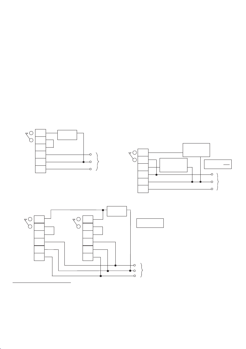
Connection Examples
MS1201PF or MS1201PSM
MS1221PF or MS1221PSM
The MS1221 has two outputs, one influenced by the
VOLTFREE
OUTPUT
*
*
NEUTRAL
R1
R1
LIVE IN
LIVE IN
EARTH
LOAD
(Max 6 Amps)
External Link
* The Live terminals are internally linked
Multiple Units
L
N
E
Permanent
or switched
supply
photocell (R1), the other not (R2). This is useful in
applications where a fan or water is being controlled in
addition to any lighting.
VOLTFREE
OUTPUT
LIVE OUT
LIVE IN
NEUTRAL
EARTH
R2
R2
R1
LOAD 1
(Max 6 Amps)
INFLUENCED
BY PHOTOCELL
LOAD 2
(Max 6 Amps)
NOT INFLUENCED
BY PHOTOCELL
TOTAL LOAD NOT
TO EXCEED 10A
L
Permanent
or switched
N
supply
E
Larger areas can be covered by connecting extra units in parallel. The total load current must not exceed 6 Amps
in case only one unit is activated.
LOAD
(Max 6 Amps)
VOLTFREE
OUTPUT
NEUTRAL NEUTRAL
R1
R1
LIVE IN
*
LIVE IN LIVE IN
*
EARTH EARTH
VOLTFREE
OUTPUT
External Link External Link
LIVE IN
*
R1
R1
*
EXAMPLE SHOWS
2 x MS1201P
* The Live terminals are internally linked
L
Permanent
or switched
N
supply
E
Important Additional Notes
1. Only suitably qualified personnel should install this equipment.
2. All terminals on this product are provided for final connections. It is not intended that the product be used as a junction box
for looping cables.
3. A means for disconnection must be incorporated in the fixed wiring in accordance with the current wiring regulations.
4. This equipment switches lights no more frequently than would a responsible human occupant. However, manufacturers of
some lighting types (e.g. ‘2D’ luminaires) may specify a maximum number of switching cycles and/or a minimum on-time in
order to achieve a predicted lamp life. Please check with the manufacturer of the luminaires to ensure that they are
compatible with automatic controls in this respect.
 Loading...