

Honeywell LYNX Touch SIA User Manual

LYNX Touch SIA
Security System
Programming Guide
800-11060-1 2/12 Rev. A

Table of Contents
Entering Programming Mode....................................................................................................................................3
Programming the Data Fields................................................................................................................................... 3
Loading a Default Set...............................................................................................................................................3
Exiting Programming Mode ......................................................................................................................................3
Data Fields................................................................................................................................................................4
Change Installer Code........................................................................................................................................... 4
Program System Type........................................................................................................................................... 4
Program Date and Time........................................................................................................................................4
Program Communications.....................................................................................................................................6
Program Zones...................................................................................................................................................... 7
Program Keys........................................................................................................................................................ 8
Program Reporter.................................................................................................................................................. 9
Program Sounder................................................................................................................................................14
Program System Settings.................................................................................................................................... 14
Program the Z-Wave Module..............................................................................................................................16
Zone Programming Worksheet ..............................................................................................................................17
Explanation of Zone Assignment Table Headings.............................................................................................. 18
5800 Series Transmitter Loop Numbers Diagram..................................................................................................19
Programming Default Tables.................................................................................................................................. 20
LYNX Touch Series Summary of Connections Diagram........................................................................................23
Refer to the LYNX Touch Series Installation and Setup Guide P/N 800-10614 or later for detailed information on
programming the system. The Installation and Setup Guide contains full descriptions for all data fields.
UL
LYNX Touch SIA is not intended for UL985 Household Fire applications unless a 24-hour
backup battery (P/N LYNXRCHKIT-SHA) is installed.
- 2 -

Entering Programming Mode
You may find it convenient to adjust the volume setting before entering the Programming Mode. This
will allow you to clearly hear feedback announcements or system beeps.
1. Power up the LYNX Touch SIA control, when the Home Screen appears, select “More”.
2. Select “Tools”. The system displays a virtual keypad.
3. Enter: Installer Code (4 + 1 + 1 + 2).
4. The System Programming Screen is displayed. Select “Program”. The Armed and Ready LEDs will flash and
the following options will be displayed:
Installer Code
Date Time
Zones
Keys
Use the down T arrow to scroll to the next page of options.
Sounder
Default Config.
* This field may not be applicable to the system being installed.
Reset Master Code
5. Select an option to advance to that Programming screen.
System Type
Communicator
Comm. Diagnostics
Reporter
System Settings
Language*
Z-Wave
Note: If a different Installer Code has been programmed, enter: the New Installer Code.
Programming the Data Fields
1. Select each desired programming option, and then select the required entry. The system beeps each time a
selection is made.
2. The system will toggle or scroll through the options or display a new screen as required for the specific
option.
3. To delete or change an entry, simply select the desired option, and then select the required entry.
Loading a Default Set:
1. Enter the Installer Programming Mode and advance to second page of the System Programming.
2. Select ‘Default Config’ and select the appropriate Default Table Configuration from the following options or
Select Default Downloader to reset all subscriber account numbers and CSID in preparation for an initial
download:
Default Config 1
Default Config 2
Default Config 3
Default Config 4
Default Downloader
Note: Refer to the Programming Default Tables section of this manual to view the default values.
Exiting Programming Mode:
1. Select the “2” key to exit the current screen. The system returns to the previous screen.
2. Select the “2” key as required until system displays a Confirmation screen.
3. Select “Yes” to allow the installer to re-enter Programming mode or “No” to prevent re-entry. If “No” is
selected, you can still re-enter Program Mode by powering down the unit (remove AC and battery power) and
entering Program Mode within 30 seconds of powering up.
4. Select the “2” key again to return to the Home Screen.
- 3 -

Screen Display Function & Programming Options
DATA FIELDS
Note: If applicable, preprogrammed defaults for the LYNX Touch SIA Control are shown on the screen display.
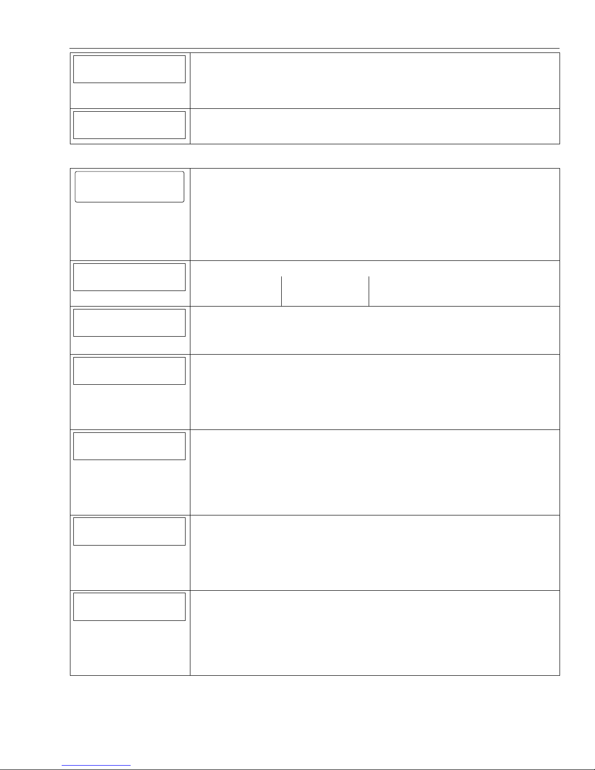
Change Installer Code
Installer Code
Installer Code
5000-100-129-V0
Enter 4 digits [The defaulted Installer Code is 4112]
0-9
Program System Type
Speaker Phone
Two Way Voice
RF House Code
Phone Notification
RF Jam
Disabled
Enabled
Disabled
0
Disabled
Phone Detect Time
2 Minutes
Remote Phone
Events - Log All
Enabled
Press To Log All
Events – Log Alarm
Events – Log Bypass
Events – Log Open Close
Events – Log Trouble
Enabled
Disabled
Disabled
Enabled
Non Security
Disabled
RF Jam
Disabled
RF Jam Log
RF Jam Log & Report
Speaker Phone
Disabled
Enabled
Two-Way Voice
Disabled
Enabled
RF House Code
Enter 2 digits, 00-31
Phone Notification
Disabled
Keypad
Trouble
Note: If “Keypad” or “Trouble” is selected you will be prompted to program a phone detect time.
Phone Detect Time
1 Minute
2 Minutes
3 Minutes
4 Minutes
Remote Phone
Disabled
Enabled
Events – Log All
Note: If Press to Log All is selected the system will log the following events:
Alarm
Bypass
Open/Close
Trouble
Non-Security
Events – Log Alarm
Enabled
Disabled
Events – Log Bypass
Enabled
Disabled
Events - Log Open/Close
Enabled
Disabled
Events – Log Trouble
Enabled
Disabled
Non Security
Enabled
Disabled
- 4 -
Screen Display Function & Programming Options
Remote Access Serial
Disabled
Remote Access Serial
Enabled
Disabled
Note: If the “Remote Access Serial” opt ion is enabled, you will be prompted to select a “Multi Mode
Multi Mode Serial
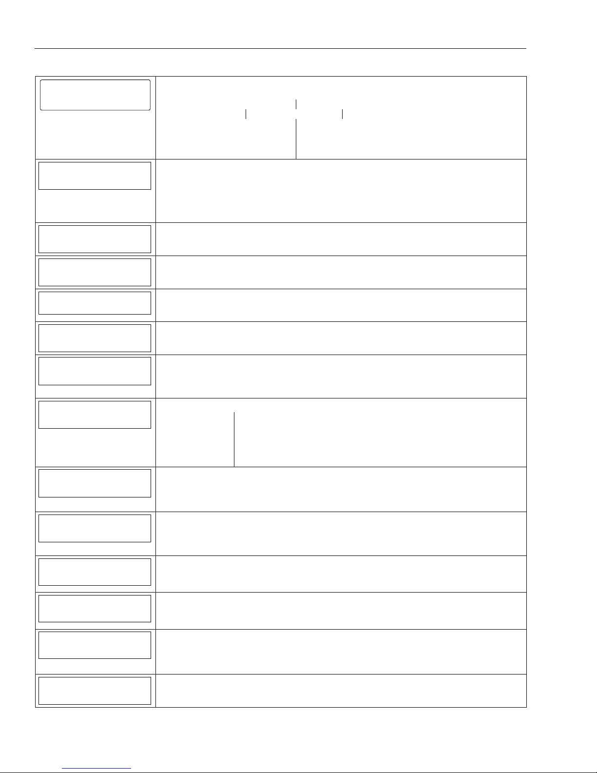
Program Date and Time
Disabled
Serial”.
Multi Mode Serial
Enhanced Reports
Disabled
Date Time
Date Time
5000-100-131-V0
Note: If you are installing a GSMVLP 5 or ILP5 Communication Module, the ti me and date will be
programmed and updated automat ically via Central Station. You must still program the correct
Time Zone below.
1. Month and Year
2. Select the correct date
3. Enter the correct time
4. Select AM or PM
Time Zone
Eastern (EST)
Day Light Savings Time
Yes
Start Month
March
5. Select Save or continue below.
Time Zone
Eastern (EST) Mountain (MST) Atlantic (AST)
Central (CST) Pacific (PST) Newfoundland (NT)
Hawaii (HAST) Alaska (AKST)
Day Light Savings Time
Yes
No
Note: If Yes is selected, the following options will be active.
Start Month
January July
February August
March September
April October
May November
June December
Start Week
Second
Start Week
First
Second
Third
Fourth
Last
Next to Last
End Month
November
3rd from Last
End Month
January July
February August
March September
April October
May November
June December
End Week
First
Start Week
First
Second
Third
Fourth
Last
Next to Last
3rd from Last
- 5 -
Screen Display Function & Programming Options
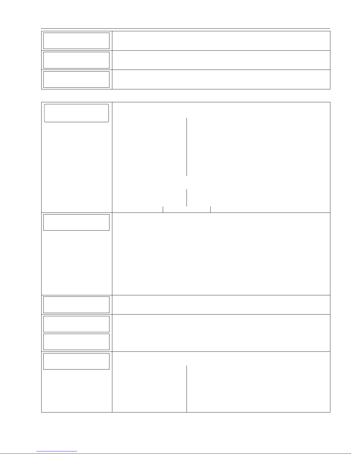
Program Communications
Communicator
Communicator
Program the following options:
5000-100-132-V0
Communications Path APL
City ID CS ID Sub ID
Supervision Old Alarm Time
Remote Acc. Comm. Multi Mode Comm.
GSM Fault Time OR
Communications Path
None
Communications Path
None
IP
IP Fault Time
GSM
WiFi
APL
Disabled
City ID
CS ID
Sub ID
Supervision
24 Hours
Old Alarm Time
10 Minutes
WiFi & GSM
Advanced Protection Logic
Enabled
Disabled
Primary City Identification
Enter 2 digits
01-99
Primary Central Station Identification
Enter 2-digits (HEX)
01-FE
Primary Subscriber Identification
Enter 4-digits
0001-9999
Supervision
24 Hours
None
30 Days
Old Alarm Time
10 Minutes 15 Minutes
30 Minutes 1 Hour
2 Hours 4 Hours
8 Hours 12 Hours
24 Hours
Remote Acc. Comm.
Multi Mode Comm.
GSM Fault Time (min)
IP Fault Time (min)
NIC IP Address
255.255.255.255
Disabled
Disabled
00
00
Use DHCP
Yes
Remote Access Communication
Disabled
Enabled
Note: If enabled the following option will be active.
Multi Mode Communication
Disabled
Relay Reports
Enhanced Reports
GSM Fault Time (min) (displayed if GSM is selected as Communications Path)
Enter 2-digits
00-99
IP Fault Time (min) (displayed if IP is selected as Communications Path)
Enter 2-digits
00-99
Use DHCP
Yes
No
Note: If disabled the following options will be active.
IP Fault Time
Enter 4 part address
- 6 -
Screen Display Function & Programming Options
255.255.255.255
Gateway IP Address
255.255.255.255
DNS Server IP Address
255.255.255.255
Subnet Mask
Subnet Mask
Enter 4 part address
Gateway IP Address
Enter 4 part address
DNS Server Address
Enter 4 part address
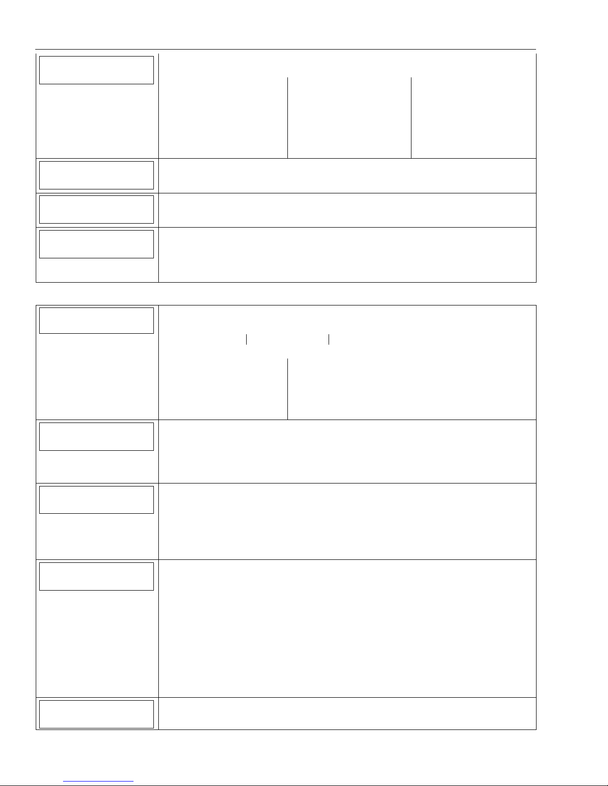
Program Zones
Zones
Serial Number
Loop Number
1
Zone Description 1
Zone Description 2
Device Type
5000-100-133-V0
Zones
Select from the following zone options:
1. New
3. Back Door
5. Motion Sensor
2. Front Door
4.Window
6.New
7. – 48. New
49. – 56. 4 Button
57. – 64. New
80. – 85. Temperature
95. Fire
96. Medical
99. Police
Select a zone and then select “Edit” or “Add New” to program the next available zone.
Program the following options:(dependent upon Zone Type):
Serial Number Loop Number
Zone Description 1 Zone Description 2
Device Type Response Type
Report Chime Supervision
Serial Number
When “Serial Number” has been selected “Enter Serial Number or Activate” is displayed.
The transmitter serial number and loop number can be enrolled via RF transmission OR
manually.
Enroll via RF Learning To enroll the device using RF Learning mode three transmissions
(open/close) of the device will be required. The initial transmission activates the RF
Learning mode and the system will emit a single beep. A second transmission enrolls the
serial number and the system beeps two times and displays “Activate Sensor Again To
Confirm”. A third transmission will confirm the serial number. The system beeps two times
and returns to the Zone programming Screen.
Enroll Manually
Enter the 7-digit serial number printed on the transmitter using the displayed keypad and
select “Done”. The system beeps one time and returns to the Zone programming Screen.
Loop Number
1, 2, 3 or 4
Zone Description 1
The system announces the Zone Description. If desired, enter a zone descriptor.
Zone Description 2
The system announces the Zone Description. If desired, enter a zone descriptor.
Device Type
Choose from the following options (dependant upon the Zone):
New Door
Window Motion Sensor
Glass Break Smoke Detector
Heat Sensor Carbon Mono. Det.
Temperature Flood
Environmental Medical
Fire Police
Other
- 7 -
Screen Display Function & Programming Options
Response Type
Not Used
Response Type
Choose from the following options (dependant upon the Device Type):
Not Used Arm Stay Fire No Verification
Entry Exit 1 Disarm Monitor
Entry Exit 2 Silent Burglary Trouble
Interior Follower Resident Response Arm Away
24 Hour Silent General Response No Response
24 Hour Auxiliary Perimeter Resident Monitor
Interior With Delay Day Night General Monitor
Carbon Monoxide 24 Hour Audible Fire With Verification
Report
Yes
Chime
No
Supervision
Supervised
Report
Yes
No
Chime
Yes
No
Supervision
Hardwire Zone
Normal Open
Normal Closed
End of Line
RF Zone
Supervised
Unsupervised
Temperature
High Temp
Low Temp
Program Keys
Keys
Key Type
4 Button Key
User
Serial Number
0
Zone
49
Keys
Select from the following options:
Edit Add New Delete
If add new is selected the following options can be programmed:
Key Type User
Serial Number Zone
Button Key 1 – Zn 49 Button Key 2 – Zn 50
Button Key 3 – Zn 51 Button Key 4 – Zn 52
Button Key 5 – Zn 53 Button Key 6 – Zn 54
Button Key 7 – Zn 55 Button Key 8 – Zn 56
Key Type
1 Button Key.
2 Button Key
4 Button Key
6 Button Key
8 Button Key
User
Master
Duress
Babysitter
User 3 through User 14
Note: The Key must be as sociated with a specific User/User Code in order for it to operate. Refer to the
LYNX Touch Series User Guide for additional Information regarding User Codes.
Serial Number
When “Serial Number” has been selected “Enter Serial Number or Activate” is displayed.
The transmitter serial number and loop number can be enrolled via RF transmission OR
manually.
Enroll via RF Learning To enroll the device using RF Learning mode three transmissions
(open/close) of the device will be required. The initial transmission activates the RF
Learning mode. A second transmission enrolls the serial number and the system beeps two
times and displays “Activate Sensor Again To Confirm”. A third transmission will confirm the
serial number. The system beeps two times and returns to the Zone programming Screen.
Enroll Manually
Enter the 7-digit serial number printed on the transmitter using the displayed keypad and
select “Done”. The system beeps one time and returns to the Zone programming Screen
Zone
Manually enter a specific two-digit Zone Number (49-64).
- 8 -
 Loading...