

Honeywell Galaxy 18Galaxy, Galaxy 8, Galaxy 504, Galaxy 60, Galaxy 512 Programming Manual
...Page 1

Galaxy
8/18/60/128/500/504/512
Programming Manual
Honeywell Security
Page 2

Page 3

Galaxy Programming Manual
Table of Contents
Contents
Section 1: Quick Setup ............................................................................. 1
Section 2: System Operation ................................................................... 3
Menu Options ......................................................................................................... 3
General................................................................................................................................... 3
The Full Menu ........................................................................................................................ 3
The Quick Menu .................................................................................................................... 3
Menu Access ......................................................................................................................... 3
Direct Access ............................................................................................................................................... 4
Menu Driven Access ....................................................................................................................................4
Keypad Menu Timeout .................................................................................................................................4
Engineer Mode ...................................................................................................................... 4
Accessing Engineer Mode (Galaxy 8, 18, 60, 128, 500 & 504) ................................................................... 4
Accessing Engineer Mode (Galaxy 512)......................................................................................................5
Exiting from Engineer Mode......................................................................................................................... 5
Multi User Access ........................................................................................................................................6
Section 3: Setting Options ....................................................................... 7
Setting the System................................................................................................................ 7
Full Setting ................................................................................................................................................... 7
Part Setting ..................................................................................................................................................7
Cancelling the Setting .................................................................................................................................. 7
Unsetting the System ........................................................................................................... 8
Engineer Unsetting (G8, 18, 60, 128, 500 and 504) ............................................................ 8
Keyswitch Setting Options .................................................................................................. 8
Setting the System with a Keyswitch ...........................................................................................................8
Unsetting the System with a Keyswitch ....................................................................................................... 8
Card Setting Options ............................................................................................................9
Setting with Proximity Cards/Tags/Fobs ......................................................................................................9
Unsetting with the Proximity Cards ..............................................................................................................9
Cancelling and Resetting Alarms ........................................................................................ 9
Setting Features .................................................................................................................. 10
Show Set Status ........................................................................................................................................10
Exit Time .................................................................................................................................................... 10
Exit Time Reset.......................................................................................................................................... 10
Omitted Zones ........................................................................................................................................... 11
Expiry Warning........................................................................................................................................... 11
System Set Indication ................................................................................................................................ 11
Group Logic Setting Restriction ................................................................................................................. 11
Entry Time.................................................................................................................................................. 11
Timeout (Slow Entry) ................................................................................................................................. 11
i
Page 4

Table of Contents
Straying from the Entry Route.................................................................................................................... 11
Abort Time .................................................................................................................................................12
Abort Setting Message ..............................................................................................................................12
Fail to Set – Galaxy 60, 128, 500, 504 & 512 ............................................................................................12
Power Failure While System is Set ............................................................................................................ 12
Galaxy Programming Manual
Section 4: Menu Options 11-19 .............................................................. 13
Option 11 – Omit Zones (Quick Menu Option 0) ............................................................. 13
Option 12 – Timed Set ........................................................................................................ 15
Option 13 – Part Set ............................................................................................................15
Option 14 – Forced Set (Quick Menu Option 1) ............................................................... 15
Option 15 – Chime (Quick Menu Option 2) ....................................................................... 15
Option 16 – Instant Set ....................................................................................................... 15
Option 17 – Instant Part...................................................................................................... 16
Option 18 – Home Set ......................................................................................................... 16
Option 19 – All Set (Galaxy 18, 60, 128, 500, 504 & 512).................................................. 16
Section 5: Display Options..................................................................... 17
Option 21 – Display Zones (Quick Menu Option 3) ......................................................... 17
Option 22 – Display Log (Quick Menu Option 4) ............................................................. 18
Option 23 – System (Galaxy 18, 60, 128, 500, 504 & 512) ................................................ 19
Option 24 – Print (Quick Menu Option 5).......................................................................... 20
Option 25 – Access Doors.................................................................................................. 21
Section 6: Test Options .......................................................................... 25
Option 31 – Walk Test (Quick Menu Option 6) ................................................................. 25
Ending the Walk Test .................................................................................................................................25
Option 32 – Outputs............................................................................................................ 26
Section 7: Modify Options ...................................................................... 27
Option 41 – Time/Date (Quick Menu Option 7)................................................................. 27
Option 42 – Codes (Quick Menu Option 8) ....................................................................... 28
Default Codes ............................................................................................................................................29
Engineer Code ........................................................................................................................................... 29
Escaping from Engineer Mode................................................................................................................... 30
Programming Codes........................................................................................................... 31
Option 43 – Summer (Quick Menu Option 9) ................................................................... 39
Option 44 – Trace (Galaxy 18, 60, 128, 500, 504 & 512) ................................................... 39
Option 45 – Timer Control (Galaxy 18, 60, 128, 500, 504 & 512) ..................................... 40
Option 46 – Group Omit (Galaxy 18, 60, 128, 500 & 504)................................................. 44
Option 47 – Remote Access ............................................................................................... 45
Option 48 – Engineer Access (Galaxy 512 only) .............................................................. 46
Option 49 – Datelock (Galaxy 512) .................................................................................... 47
ii
Page 5

Galaxy Programming Manual
Table of Contents
Section 8: Engineer 1 .............................................................................. 48
Option 51 – Parameters ...................................................................................................... 48
Assigning Parameters to Groups ...............................................................................................................48
Option 52 – Program Zones ............................................................................................... 65
Selecting Zones .........................................................................................................................................65
Attributes.................................................................................................................................................... 65
System Alarms ...........................................................................................................................................68
Option 53 – Program Outputs ............................................................................................ 81
Selecting Outputs ...................................................................................................................................... 81
Attributes.................................................................................................................................................... 82
Output Functions ....................................................................................................................................... 85
Option 54 – Links (Galaxy 18, 60, 128, 500, 504 & 512) ................................................... 96
Programming Links ....................................................................................................................................96
Option 55 – Soak ................................................................................................................. 99
Programming Soak Zones .........................................................................................................................99
Option 56 – Communications .......................................................................................... 100
1 = Telecoms............................................................................................................................................ 100
2 = RS232 ................................................................................................................................................100
3 = ISDN ..................................................................................................................................................100
4 = Ethernet .............................................................................................................................................100
Telecom Module .......................................................................................................................................101
RS232 Interface Module .......................................................................................................................... 113
ISDN Module ........................................................................................................................................... 115
Ethernet Module ...................................................................................................................................... 123
Option 57 – System Print ................................................................................................. 134
Selecting a Print Option ...........................................................................................................................134
Option 58 – Keypad .......................................................................................................... 135
Option 59 – Quick Menu ................................................................................................... 138
Modifying the Quick Menu .......................................................................................................................138
Section 9: Engineer 2 ............................................................................ 139
Option 61 – Diagnostics ................................................................................................... 139
Option 62 – Full Test (Galaxy 18, 60, 128, 500, 504 & 512) ............................................ 140
Option 63 – Options (Galaxy 18, 60, 128, 500, 504 & 512) ............................................. 141
Option 64 – Assemble Zone (Galaxy 18, 60, 128, 500, 504 & 512) ................................ 151
Programming a Custom Zone .................................................................................................................. 151
Option 65 – Timers (Galaxy 18, 60, 128, 500, 504 & 512) ............................................... 155
Timer A and B .......................................................................................................................................... 156
Autoset (Galaxy 18, 60, 128, 500, 504 & 512) .........................................................................................157
Lockout (Galaxy 512) ...............................................................................................................................159
Option 66 – Pre-checks (Galaxy 60, 128, 500, 504 & 512).............................................. 161
Testing Zones ..........................................................................................................................................161
Option 67 – Remote Reset ............................................................................................... 162
Option 68 – Menu Access (Galaxy 60, 128, 500, 504 & 512) .......................................... 163
iii
Page 6

Table of Contents
Galaxy Programming Manual
Appendix A : Door Control - MAX (MX01) ........................................... A-1
Installation Instructions..................................................................................... A-1
Wiring the MAX ................................................................................................................. A-1
Mounting the MAX ............................................................................................................ A-2
Surface Mounting the MAX ...................................................................................................................... A-2
Flush Mounting the MAX.......................................................................................................................... A-2
Configuring a MAX Reader into the System................................................................... A-3
Configuring as a Stand-Alone MAX ................................................................................ A-3
Configuring as On-Line MAX ........................................................................................... A-4
Removing a MAX Reader from the System .................................................................... A-5
Stand Alone Mode (Software V1.23 & V1.32) ......................................................................................... A-5
On-Line Mode .......................................................................................................................................... A-5
Programming Instructions for On-Line Readers ........................................................... A-5
Operating Instructions (On-Line Modes) ........................................................................ A-6
Gaining Access ........................................................................................................................................ A-6
Card-Held Function .................................................................................................................................. A-6
Max Log ............................................................................................................................. A-7
Max Events Print-Out ............................................................................................................................... A-7
Appendix B: Library .............................................................................. B-1
Appendix C: SIA and Contact ID Event Codes ................................... C-1
Appendix D: SIA Event Structure ....................................................... C-1
Appendix E: Event Log Messages ....................................................... D-1
Index ............................................................................................................ 1
iv
Page 7
Galaxy Programming Manual
Quick Setup
Section 1: Quick Setup
To quickly set up the Galaxy control panel for programming follow these simple steps:
1. Connect a 1k Ω (1%) resistor across each of the zones on the panel and RIO (if connected).
2. Ensure that the tamper return loop — the terminal marked as
NOTE: This is factory set as a completed loop with a 0 V return.
3. Connect a keypad to the AB LINE terminals on the control panel. The Galaxy 128 has two AB lines.
The Galaxy 500, 504 and 512 have four AB LINE terminals. Connect the terminals as follows:
lenaPlortnoCdapyeK
BB
AA
Table 1. Terminal Connections
4. Connect a 680 Ω End Of Line (EOL) resistor across the A and B terminals of the keypad.
5. Ensure that the keypad is fitted to the wall (see Installation Manual, II1-0030, Keypad
Installation Procedure, Section 4).
6. Connect the battery before replacing the control panel lid.
++
--
T on the PCB — is a complete loop.
7. Make sure that the backup battery switch on the PCB (MEM BK) is closed.
8. Connect the mains wiring to the control panel. Do not switch the mains ON.
9. Replace the control panel lid and secure the fastening screw.
10. Switch on the mains voltage (230 Va.c. / 50 Hz).
11. The following sequence of events occur:
• the keypad buzzer and control panel horn (if fitted) activate momentarily,
• flashing ✷✷✷✷✷✷✷✷✷✷✷✷✷✷✷✷ is displayed on the keypad,
• the sounders stop and the keypad displays become blank,
• the green power LED lights,
• the default banner is displayed on the keypad.
GALAXY <Panel Type> <Panel Version>
00:00 SUN 01 JAN
12. The system is now ready to be programmed. Refer to Section 2: System Operation for
programming details.
1
Page 8

Galaxy Programming Manual
2
Page 9
Galaxy Programming Manual
Menu options
Section 2: System Operation
Menu Options
General
The Galaxy provides various menu options for modifying the functional performance of the system.
There are two menu structures:
1. Full Menu — only accessed by default by the Manager code on the Galaxy 60, 128, 500, 504
and 512 control panels and by the engineer.
2. Quick Menu — a selection of options from the full menu. The quick menu is the default menu
access for all user codes (level 3 and above) as well as the Manager code on the Galaxy 8 and 18
control panels.
The Full Menu
The full menu has a hierarchy of four structures contained within it. Each structure is accessible by an increased level of user code.
The Quick Menu
The quick menu offers level 3 and above users a selection of up to 10 options, numbered 0 – 9. The options
available from the quick menu can be modified to the user’s requirement via option
59 = QUICK MENU.
uneMkciuQuneMlluF
3leveL4leveL5leveL6leveLreenignEreenignE
senoZtimO=0gnitteS=01yalpsiD=02tseT=03yfidoM=041reenignE=052reenignE=06
teSdecroF=1senoZtimO=11senoZyalpsiD=12tseTklaW=13etaD/emiT=14sretemaraP=15scitsongaiD=16
emihC=2teSdemiT=21goLyalpsiD=22stuptuO=23sedoC=24senoZmargorP=25tseTlluF=26
senoZyalpsiD=3teStraP=31metsyS=32remmuS=34stuptuOmargorP=35snoitpO=36
goLyalpsiD=4teSdecroF=41tnirP=42ecarT=44skniL=45enoZelbmessA=46
tnirP=5emihC=51srooDsseccA=52lortnoCremiT=54kaoS=55sremiT=56
tseTklaW=6teStnatsnI=61 timOpuorG=64noitacinummoC=65kcehC-erP=66
etaD/emiT=7traPtnatsnI=71 sseccAetomeR=74tnirPmetsyS=75teseRetomeR=76
sedoC=8teSemoH=81 sseccA.gnE=84dapyeK=85sseccAuneM=86
remmuS=9teSllA=91 kcolemiT=94uneMkciuQ=95
Table 2. Quick and Full Menu Options Reference
Menu Access
Only valid codes (level 3 and above) can access the Galaxy menu options. Access to the user options is
assigned by the engineer (refer to options 42 = CODES and 68 = MENU ACCESS). Users cannot view or
access options for which they are not authorised; this includes options in the Quick Menu.
NOTE: Menu options 51 – 67 (ENGINEER 1 and ENGINEER 2) can be assigned additional access to
user level 3 – 6, by the engineer.
3
Page 10

Menu Access
There are two methods of selecting menu options:
1. Direct Access:
Code + ent + option number + ent.
2. Menu Driven Access:
Code + ent + A (to select menu level) + ent;
A key (to select menu option) + ent.
Galaxy Programming Manual
Direct Access
Entering a valid menu option number while in the menu immediately moves to that option. For example, pressing 52 when the keypad is displaying 22 = DISPLAY LOG moves directly to option
52 = PROGRAM ZONES; Pressing 8 while accessing the PROGRAM ZONES option moves directly to
8 = Group. The option number entered must be valid for the level of the menu structure that is currently being
accessed.
Menu Driven Access
Menu driven access allows the engineer (and users) to enter the menu and, by using the A and B keys, navigate through the available options. The options are accessed by pressing the ent key. If you press and hold
the A key it will scroll forward through the options and if you press and hold the B key it will scroll backwards
through the options.
Keypad Menu Timeout
Once the user menu has been accessed (irrespective of user level), if there are no keypresses for 2 minutes,
then the keypad timeout occurs; the system returns to the banner text.
NOTE: This feature does not apply when the system is in the Walk Test option. If no zones are tested or no
keypresses occur for 20 minutes when Walk Test is selected, then the keypad timeout occurs. In
Menu Option 66 (Pre-check) there is also a 20 minute timeout after the last zone has been
activated.
Engineer Mode
To program the Galaxy, the system must be in engineering mode. This allows access to the engineer menu
options 50 = ENGINEER 1 and 60 = ENGINEER 2.
Accessing Engineer Mode (Galaxy 8, 18, 60, 128, 500 & 504)
To access engineer mode, enter the engineer code twice.
Engineer Code + ent + Engineer Code + ent
The default engineer code is 112233.
The first entry of the code activates a tamper alarm. The second entry of the code cancels this alarm and puts
the system into engineer mode; 10 = SETTING, [ENT] TO SELECT is displayed on the keypad. While
engineer mode is accessed, all tampers are disabled, however, all constantly alert zone types — PA zone
types, 24 Hour, Security, Fire & Mask — remain active.
On accessing engineering mode, any group that is set becomes inaccessible to the engineer. The set groups
cannot be assigned to zones, outputs and any other functions permitting group allocation.
NOTE: The Galaxy 60, 128, 500 and 504 can be assigned manager authorised engineer access by adding a # to
the engineer code. Engineer access is then gained as described in the following paragraphs.
4
Page 11

Galaxy Programming Manual
Engineer Menu
Accessing Engineer Mode (Galaxy 512)
User Authorised Access
The default engineer code (112233) on the Galaxy 512 is allocated a #. With the # assigned, the engineer
code operation is as follows:
1. Enable Engineer Access:
User Code + ent + 48 + ent + 1 + ent + esc + esc
2. Access Engineer Mode
Engineer Code + ent
Entry to the engineer mode is authorised by a user with access to menu option 48 = ENGINEER ACCESS.
The user selects this option and presses key 1 to enable engineer access. The engineer code must then be
entered within five minutes of the option being enabled. A single entry of the engineer code directly accesses
the mode, without activating an engineer tamper alarm. If the code is not entered within the five minute period,
the engineer code is invalid and has no effect. Once the engineer mode has been accessed, there is no time
limit on the period that the engineer can remain in the mode.
On accessing engineering mode, any group that is set becomes inaccessible to the engineer. The set groups
cannot be assigned to zones, outputs and any other functions permitting group allocation.
Galaxy 512 only
The system cannot be set by any user codes while engineer mode is accessed.
Disabling User Authorisation of Engineer Access
The remote code (User 200 on G60, User 250 on G128, User 500 on G500 and User 999 on G504 and
G512) can remove the # from the engineer code. If the # is removed access to engineer mode is gained in the
same manner as the Galaxy 8, 18, 60, 128, 500 and 504; the engineer code must be entered twice to gain
menu access.
NOTE: The engineer code or remote code can assign the # to the engineer PIN. Only the remote code can
remove it.
Exiting from Engineer Mode
To exit from engineer mode and return to the normal banner enter, carry out the following operation:
1. Return to the engineer banner,
2. Enter the engineer code,
3. Press the esc key.
The Galaxy carries out the following checks:
1. That there are no module or zone tampers. If there are any module or zone tampers the escape
procedure is aborted.
2. That it is communicating with all of the attached modules.
If any modules are reported as missing from the system, the Galaxy prompts the engineer to
remove each of the missing modules by pressing the ✴ key. If the engineer does not remove the
missing modules, the escape procedure is aborted.
5
Page 12

User Access
3. That all of the access doors (controlled by the on-line MAX) are closed. If any of the access doors
are open, then the exit procedure is halted until all of the doors are closed.
4. That there are no power failures on the galaxy system, such as AC fail, fuse fail or battery fail
Aborting the Exit Engineer Mode Procedure
If the esc key is pressed at any point while engineer mode is being exited, before the normal banner is displayed, the exit procedure is aborted and the system returns to the engineer banner.
Galaxy Programming Manual
Multi User Access
The Galaxy 60, 128, 500, 504 and 512 allow multi-user access. A maximum of 4, 8, 8, 16 and 16 users
respectively can simultaneously carry out tasks on the system.
The Galaxy 8 and 18 only permit single-user access.
6
Page 13

Galaxy Programming Manual
Setting the System
Section 3: Setting Options
Setting the System
Full Setting
Enter: USER CODE + A
If groups are enabled and the user code has been assigned group choice then the keypad displays the set
status of the available groups:
R = Ready
F = Fault (group is unset and at least 1
zone is open
P = Part Set
S (flashing) = selected for setting
S (steady) = already set
L = Lockout
SET A12345678
Groups RRSRSSSS
Pressing the keys for the groups toggles the R (Ready) to an S (set flashing).
SET A12345678
Groups SSRR---
Once the required groups have been selected press the ent key to begin the setting procedure.
If groups are not enabled or the user does not have group choice, entering the user code followed by the A
key immediately starts the setting procedure.
TIMED 060
The keypad displays the exit time countdown. At the end of the exit time, or when the setting procedure is
terminated by a FINAL or PUSH-SET zone closing, the ENTRY/EXIT HORN outputs and keypad
buzzers become silent for 4 seconds, then emit 2 long tones to confirm that the system is set. The message
SYSTEM IS SET appears briefly before the keypad display clears (if all groups are set). Otherwise, it is the
customer banner that is displayed.
PART SET 060
Part Setting
Enter: CODE + B
This is identical to the Full Setting procedure, except the keypad display indicates that the system is being
Part Set. Only the zones which have the Part attribute enabled (refer to option 52.5 = PROGRAM
ZONE.Part), are included.
Cancelling the Setting
The full and part setting routines can be aborted by pressing the esc key (on the keypad used to begin setting)
before the system sets.
7
Page 14

Unsetting the System
Galaxy Programming Manual
Unsetting the System
During the unsetting procedure, initiated by the opening of FINAL or ENTRY zone on a set group, the
system is unset by entering the user code followed by the A key.
• If the user does not have group choice, all of the groups assigned to the code are instantly unset.
• If the user has group choice only the group that the FINAL or ENTRY zone is assigned to is
unset; all of the other groups remain set. The system displays the set status of the remaining
groups and prompts for the required groups to be unset. To unset the required groups press the
relevant number keys — the S or P (Set or Part Set) changes to flashing U — and then press the
ent key.
Engineer Unsetting (G8, 18, 60, 128, 500 and 504)
The engineer can only unset a system that was set using the engineer code. The engineer code cannot be used
to unset a system that was set by a user code.
Keyswitch Setting Options
Zones programmed as KEYSWITCH can be used to full set, part set and unset the system. Refer to option
52 = PROGRAM ZONE.
Setting the System with a Keyswitch
The KEYSWITCH starts the setting procedure of each of the groups assigned to zone. At the end of the exit
time, or when the setting procedure is terminated by a FINAL or PUSH-SET zone closing, the ENTRY/
EXIT HORN outputs and keypad buzzers become silent for 4 seconds, then emit 2 long tones to confirm
that the system is set.
NOTE: If the KEYSWITCH has its Part attribute enabled (refer to option 52 = PROGRAM ZONE) then
the KEYSWITCH part sets the system.
Unsetting the System with a Keyswitch
Activating the KEYSWITCH when the group that it is assigned to is set instantly unsets the group. All other
groups which have been “starred” to the KEYSWITCH are not affected and remain set.
8
Page 15

Galaxy Programming Manual
Card Setting
Card Setting Options
Setting with Proximity Cards/Tags/Fobs
The Proximity user cards can be used to set and unset the system. This is done by assigning a MAX user
card (or fob) with one of the setting options (refer to option 42.1.8 = CODES.User Codes.MAX Func-
tion). When the card is held against a MAX module or keyprox for 5 seconds, the MAX function is activated. For example, if the MAX function assigned is 13 = Part Set, then activating the card held function
results in the system being part set.
Unsetting with the Proximity Cards
If any of the groups assigned to the MAX or keyprox are set, then swiping the MAX or keyprox module with
a card unsets the groups.
NOTE: The MAX or keyprox module must have common groups to the proximity card user to allow the
card held function to be activated.
Cancelling and Resetting Alarms
Following each alarm activation, the alarm must be cancelled and the Galaxy reset. The alarm is cancelled by
entry of any valid user code (level 2 and above) assigned to the group that has alarmed or by presentation of a
valid proximity card to a reader or keyprox. The alarm sounders, Bell and Strobe outputs are silenced and
the keypad displays information on the zones that have been activated during the alarm.
If the user code entered is not of a sufficient level to reset the Galaxy, the keypad displays the message CALL
MANAGER RESET REQUIRED or CALL ENGINEER RESET REQUIRED depending on the type
of alarm and level of reset required.
The Galaxy is reset by entering a valid user code assigned to the group that has alarmed, with the appropriate
reset level for the type of alarm that has activated — System, Tamper or PA (refer to option 51.6 =
PARAMETERS.System Reset, 51.7 = PARAMETERS.Tamper Reset and 51.22 =
PARAMETERS.PA Reset). The keypad displays information on the zones that have been activated during
the alarm.
NOTE: If a tamper alarm has activated (zone or module) then the system cannot be reset until the tamper
condition is restored.
Galaxy 8, 18, 60, 128, 500 and 504
On the next setting of the Galaxy, if any of the zones that were opened during the previous alarm have not
closed since the alarm activation, then the system is prevented from setting. The addresses of the open zones
are displayed on the keypad; there is no sounder activation. Closing the zones permits the setting procedure to
start.
NOTE: This is not the same as open zones being indicated on the keypad; these are accompanied by rapid
tones on the Entry/Exit Horn.
9
Page 16
Setting Features
Galaxy Programming Manual
Setting Features
The Galaxy control panels provide a range of features to assist the user in the setting and unsetting of the
system, minimising the possibility of error when carrying out these procedures.
Show Set Status
When Show Status is enabled (refer to option 58.6 = KEYPAD.Show Status), pressing the ✴ and # keys
simultaneously when the normal banner is displayed indicates the group set status.
F = Fault
R = Ready
S = Set
P = Part Set
L = Locked Out
– = Group not assigned to keypad
NOTE: The Show Status indicates the set conditions of groups when the system is set (keypad blank) or
unset (normal banner). Show Status does not operate while engineer mode is accessed.
Pressing the ✴ and # keys again toggles the display to show the status of the groups individually. To move
between each groups, press the ✴ and A or the ✴ and B keys simultaneously.
Pressing the ✴ and # keys again returns the keypad to the banner display.
STATUS 12345678
Groups RRSRLPFP
Group Block
08:58 TUE 22 NOV
A1U Group A1
Group A1 is unset
Galaxy 500, 504 and 512
The Galaxy 500, 504 and 512 have more than 8 groups; these are displayed on the keypad in blocks of eight
groups. Press ✴ and A or ✴ and B keys to display each of the group blocks.
Exit Time
Once the setting routine starts, outputs programmed as Entry/Exit Horn emit a continuous tone. The keypad
used to set the system indicates the time, in seconds, remaining before the system sets.
Exit Time Reset
If any zones are open when setting starts or are opened during the setting routine, the sounder begins to pulse
rapidly; zones types other than Final, Exit, Entry or Push-Set (and Secure Final or Part Final when acting
as a Final), indicate on the setting keypad the number of zones open. The A or B keys can be used to view
the open zone types and addresses. Closing the zones resets and restarts the exit time.
10
Page 17

Galaxy Programming Manual
Setting Features (cont’d)
Omitted Zones
If zones are omitted when the system starts setting, this is indicated on the keypad. The keypad indicates how
many zones are omitted.
Expiry Warning
During the last 25% of the programmed exit time outputs programmed as Entry/Exit Horn begin to pulse
rapidly, indicating that time is running short.
System Set Indication
At the end of the exit time the Entry/Exit Horns become silent for four seconds. This allows the door to be
locked and secured and gives the detectors time to settle before the system finally sets. Two long tones are
emitted to confirm that the system has set. If all groups are set the keypad briefly displays the message SYS-
TEM IS SET before going blank. If any group remain unset the display returns to the banner.
Group Logic Setting Restriction
If Setting Logic has been assigned to a group (refer to 63.1.2 = OPTIONS.Groups.Setting Logic), the set
status of the groups must satisfy the conditions defined in the option to permit the group to set. If the Setting
Logic conditions are not satisfied, then the group cannot set. If multiple groups are being set simultaneously,
but one group is restricted due to the programmed Setting Logic, the remainder of the groups set. The
restricted group does not set; there is no warning or indication given.
If the programmed Setting Logic results in none of the selected groups being allowed to set, a warning
message is displayed on the keypad. This message does not appear if at least one group sets.
2 Groups not set
[<],[>] to view
Entry Time
The system begins the unsetting routine whenever a Final or Entry zone activates. The Entry/Exit Horns
pulse slowly indicating that the entry time countdown has started. The user must go directly to the keypad,
using the agreed entry route, and unset the system before the entry time expires. When 75% of the entry time
has elapsed the Entry/Exit horns pulse rapidly, indicating that time is running short.
Timeout (Slow Entry)
If the entry time expires before a valid code is entered to unset the group, a full alarm occurs. This is recorded
in the event log as a Timeout against the group which was in the process of being unset.
Straying from the Entry Route
If, during the entry routine, the user strays from the agreed entry route and activates a zone in a protected
area, a full alarm occurs.
11
Page 18

Setting Features (cont’d)
Galaxy Programming Manual
Abort Time
Should the user exceed the entry time or stray from the entry route a full alarm occurs. However the activation
of the intruder output can be delayed to allow time for the user to abort the remote signalling.
The Abort Time parameter can also be programmed so that an Intruder alarm is activated immediately the
entry time expires or a zone is activated, but entry of any valid code cancels the alarm and deactivates the
Intruder outputs without the need for a system reset.
Abort Setting Message
Zones that are open or opened during the exit period are indicated to the user by a rapid audible tone from the
entry/exit horns. The keypad displays the open zones and then prompts the user to abort the setting by pressing the ESC key. This message is designed to prevent users from re-entering the building, closing the open
zones, allowing the system to set and trapping the user in the building.
Fail to Set – Galaxy 60, 128, 500, 504 & 512
An output type (Option 53-Program output 40, Fail Set) is available that activates if a full set has not
occurred after a programmed period of time (determined by Option 51-Parameter 35, Fail to Set) from the
start of the setting procedure.
Power Failure While System is Set
When power is restored to the system, following a complete mains (a.c.) and standby battery (d.c.) power
failure, the system attempts to return to the set status — full or part — prior to the power failure. The system
begins the setting procedure. If there are no zones open that prevent the system from setting, at the end of the
programmed exit time, the appropriate groups and parts are set.
12
Page 19

Galaxy Programming Manual
11 - Omit Zones
Section 4: Menu Options 11-19
Option 11 – Omit Zones (Quick Menu Option 0)
Code + ent + 11 + ent + A or B to select zone + # +
A or B to select zone + # + ..........
ent (to set) or esc (to select another option)
This option allows zones to be temporarily removed (omitted) from the system. Once a zone has been omitted
it does not generate an alarm condition (including tamper). The omitted zones are reinstated automatically
when the system is unset or manually when the zone omit option is disabled.
On selecting the Omit Zones option, the first zone that has the omit attribute enabled is displayed (refer to
option 52 = PROGRAM ZONE). If there are no omittable zones, then the message NO ENTRIES is
displayed.
Press the A or B keys to view other omittable zones. Press the # key to toggle the omit status of the required
zone. The display indicates the new omit status.
NOTE: A zone is omitted from the system as soon as it is selected.
This process is continued until all the required zones have been omitted:
• pressing the ent key starts the timed setting routine. The number of zones omitted from the system are
displayed during the exit time countdown;
• pressing the esc key returns to the 11 = OMIT ZONES without starting the setting routine.
On returning to the banner (normal or engineer) the keypad displays the message ZONES OMITTED.
Omitted zones remain omitted for one set period only or until they are manually reinstated to the system.
Outputs programmed as Zone Omit (mode programmed as reflex) are activated as soon as the zone is
omitted and remains active until the zone is reinstated.
13
Page 20

11 - Omit Zones (cont’d)
Galaxy Programming Manual
Galaxy 512
Code + ent + 11 + ent + A or B to select zone + # + ent (to set) or esc (to select another option)
The Omit Zones option allows a single eligible zone to be omitted from the system. Once a zone has been
omitted from the system, it is not possible to view other zones that have the omit attribute enabled until the
omitted zone is reinstated (either automatically or manually).
There are five zone types which vary from the standard Omit Zones operation:
• Vibration Zones — if the omitted zone is a Vibration zone, then all zones (in all groups) programmed as
this type are block omitted. The Vibration zones remain omitted until they are manually reinstated.
Unsetting the system does not reinstate Vibration zones (vibration zones are also available on the G504).
• ATM1/2/3/4 Zones — a single ATM zone type can be omitted for the duration of the period entered in
the ATM Timeout parameter (option 51.39). The ATM Delay parameter (option 51.38) determines
the delay before ATM zones are omitted following the entry of one of the ten ATM Codes (User 188 –
197). Entry of a code allows the user to omit one of the ATM zone types. Once omitted, the initiating
keypad indicates the number of minutes remaining until the selected ATM zones are reintroduced to the
system. A warning is given ten and five minutes before the zones are reinstated. The omit time may be
extended indefinitely by reentering an ATM Code. Outputs programmed as ATM1/2/3/4 active when the
respective AT M zone type is omitted, and remain active until the zone type is reinstated.
Refer to option 52 = PROGRAM ZONES for details on the operation of Vibration and ATM zone types.
Manually Reintroducing Omitted Zones to the System
Selecting the OMIT ZONES option; using the A or B keys, select the omitted zone to be reinstated. Press
the # key toggle the omit status of the required zone. The display indicates the new omit status.
Normal Setting with Omitted Zones
Initiate the full or part setting routine. The system starts to set; the display indicates that zones have been
omitted. The zone remains omitted until the system is unset (with the exception of Vibration and ATM
zones).
14
Page 21

Galaxy Programming Manual
Options 12 - 16
Option 12 – Timed Set
This option, when entered, starts the setting routine. The Entry/Exit Horns emit the expiry warning using the
programmed exit time (0-300 seconds). The system sets at the end of the exit time or earlier if a Final Zone is
opened and closed, key 0 is pressed — if programmed as an exit terminator — or if a push-set terminator is
operated. The option displays the time remaining until the system sets or the number of open zones preventing
the system from setting. Opening a zone during the exit routine resets the exit timer. Pressing the esc key prior
to the system setting aborts the setting routine.
NOTE: The factory default setting allows the timed setting routine to be initiated by entering a valid level 3
(or above) user code and pressing the A key. The A key can be reprogrammed by the engineer to
perform another function, or to start the setting routine without a code being entered.
Option 13 – Part Set
This option operates exactly as the Timed Set option with the exception that only those zones that have the
part attribute enabled (refer to option 52 = PROGRAM ZONES) are set. All zones have the part attribute
enabled by default. Therefore selecting PART SET from the factory will set all zones. The part attribute of
the zones must be disabled if they are not to be included in the part set.
NOTE: The factory default setting allows the part setting routine to be initiated by entering a valid level 3 (or
above) user code and pressing the B key. The B key can be reprogrammed by the engineer to
perform another function, or to start the part setting routine without a code being entered.
Option 14 – Forced Set (Quick Menu Option 1)
Forced Set allows a timed set of the system when there are zones that are open at the point of selecting
the option. The open zones must have the omit attribute enabled (refer to option 52 = PROGRAM
ZONES). This option is only available if the Forced parameter (option 51.26) is enabled; otherwise, the
selection is invalid and the keypad displays the message Option not available.
When the Forced Set option is entered, the keypad displays the number of zones that have been omitted
(manually by option 11 = OMIT ZONES and automatically by the Forced Set) and the setting routine
begins. If there are any open zones that do not have the omit attribute enabled, the keypad displays the
number of open zones that are not omittable and prompts the user to view them. The non-omittable zones
must be closed before the setting routine can continue.
Option 15 – Chime (Quick Menu Option 2)
The Chime option allows the user to switch the chime facility on and off. Any zones that have the chime
attribute enabled (refer to option 52 = PROGRAM ZONES) momentarily operate Entry/Exit Horns when
opened; 2 long tones are emitted.
Option 16 – Instant Set
Selecting this option immediately sets all zones. No sounder or exit time is involved.
NOTE: The zones must be closed to allow the system to set. If any zones are open, then the exit time reset
feature (detailed previously) is activated.
15
Page 22

Options 17 - 19
Galaxy Programming Manual
Option 17 – Instant Part
Selecting this option immediately sets all zones that have the part attribute enabled. No sounder or exit time is
involved.
NOTE: The zones must be closed to allow the system to part set. If any zones are open, then the exit time
reset feature (detailed previously) is activated.
Option 18 – Home Set
The Home Set option either fully sets or part sets the system. The system is:
• fully set if the exit time is manually terminated via a Final or Push-Set zone operation;
• part set if the exit time is allowed to expire.
Option 19 – All Set (Galaxy 18, 60, 128, 500, 504 & 512)
All Set allows a timed set of groups assigned to the user code without offering the choice of which groups are
to be set. No group choice is offered. The groups that are set when this option is selected is determined by the
keypad group restriction (refer to option 58.7 = KEYPADS.Groups):
• If there is no keypad group restriction then all of the groups assigned to the user are set — as long as
there is at least one common group assigned to the keypad.
• If there is a group restriction on the setting keypad, then only the groups that are common to both the user
and the keypad on which the menu option is selected are set. For example, a user assigned groups 1, 2, 3,
and 4 selecting the All Set option on a keypad assigned groups 2 and 3 will only set groups 2 and 3.
16
Page 23

Galaxy Programming Manual
21 - Display Zones
Section 5: Display Options
Option 21 – Display Zones (Quick Menu Option 3)
Selecting and entering the Display Zones option shows the first zone on the system. Other zones may be
viewed by pressing the A and B keys or by entering the zone number directly.
The top line displays:
• the address;
• the zone function alternating with the status — open, closed, high resistance, low resistance, tamper short
or tamper open circuit;
• the group assigned — if the group mode is enabled. Only the zones assigned to the user’s group are
displayed.
The bottom line shows:
• the zone descriptor (if used);
• by pressing the # key the bottom line changes to show the circuit resistance in Ohms, if using a hardwired
RIO and the RIO (not zone) voltage, pressing the # key returns the bottom line to the zone descriptor.
A printout of all the zones is available from this option by pressing the ✴ key; pressing the esc key aborts the
printout.
NOTE: A serial printer must be connected to the Galaxy panel via a printer interface module or an RS232
interface module.
17
Page 24

22 - Display Log
Galaxy Programming Manual
Option 22 – Display Log (Quick Menu Option 4)
The Galaxy event log is viewed using this menu option. The number of events that each of the Galaxy panels
can store are as follows:
• Galaxy 8 - 250 events
• Galaxy 18 - 500 events
• Galaxy 60 - 500 events
• Galaxy 128 - 500 events
• Galaxy 500 - 1000 events
• Galaxy 504 - 1000 events
• Galaxy 512 - 1000 events
If group mode is enabled (refer to option 63 = OPTIONS) and the user code has group choice (refer to
option 42 = CODES), then the available groups are displayed for selection. Press the number of the groups
to be displayed, the N below the selected group changes to a flashing Y. When all the required groups are
selected press the ent key to access the log; only the events in the selected groups are displayed.
Once the event log is accessed, the most recent event is displayed. The B key steps backwards in time
through the log, while the A key moves forward in time. Holding down either key quickly steps through the
dates until the required date is found. When a selected date is on display the events of that day and previous
days can be viewed by repeatedly pressing the B key; events on subsequent days are viewed by repeatedly
pressing the A key.
The event log is wrapped round from beginning to end. The message START or END (depending on
whether the A key or the B key is being pressed) is briefly displayed when the wraparound is passed through.
The following information is detailed in the event log:
• time - time that event occurred;
• date - day and date that event occurred;
• event - information about the type of event that occurred. Certain events are displayed with a +
(positive — indicating that the event started or was activated) or – (negative — indicating that the event
ended or was terminated) symbol;
• user - alternates between the name and number of the user who initiated the event. If the event is
one that is not associated with a user code, for example, an alarm activation or a Final zone
closing, then no user information is displayed.
Pressing the # key while viewing the log can reveal additional information about certain event types:
• User events reveal the keypad, user level and user group involved in the event;
• Alarm events reveal the zone descriptor, if programmed.
• Walk tested RF zones reveal the measured signal strength of each RF device.
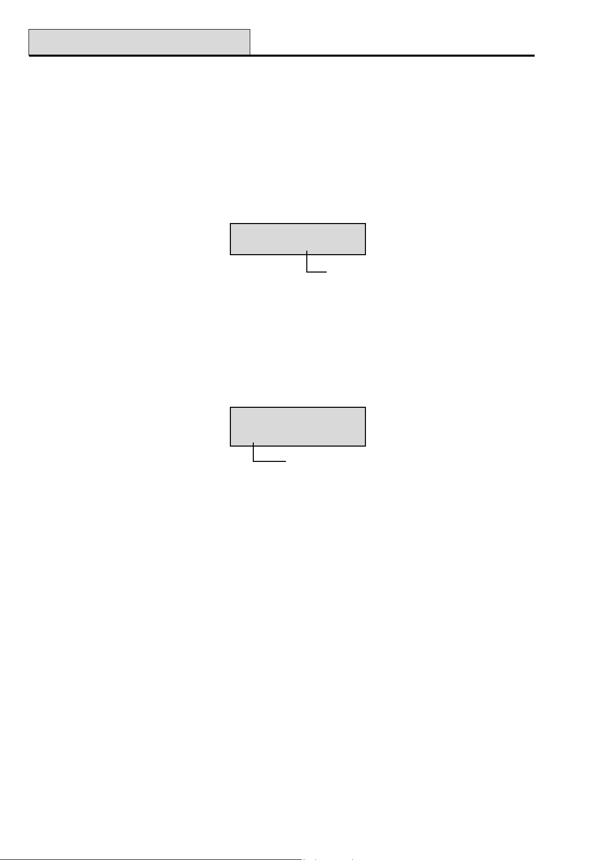
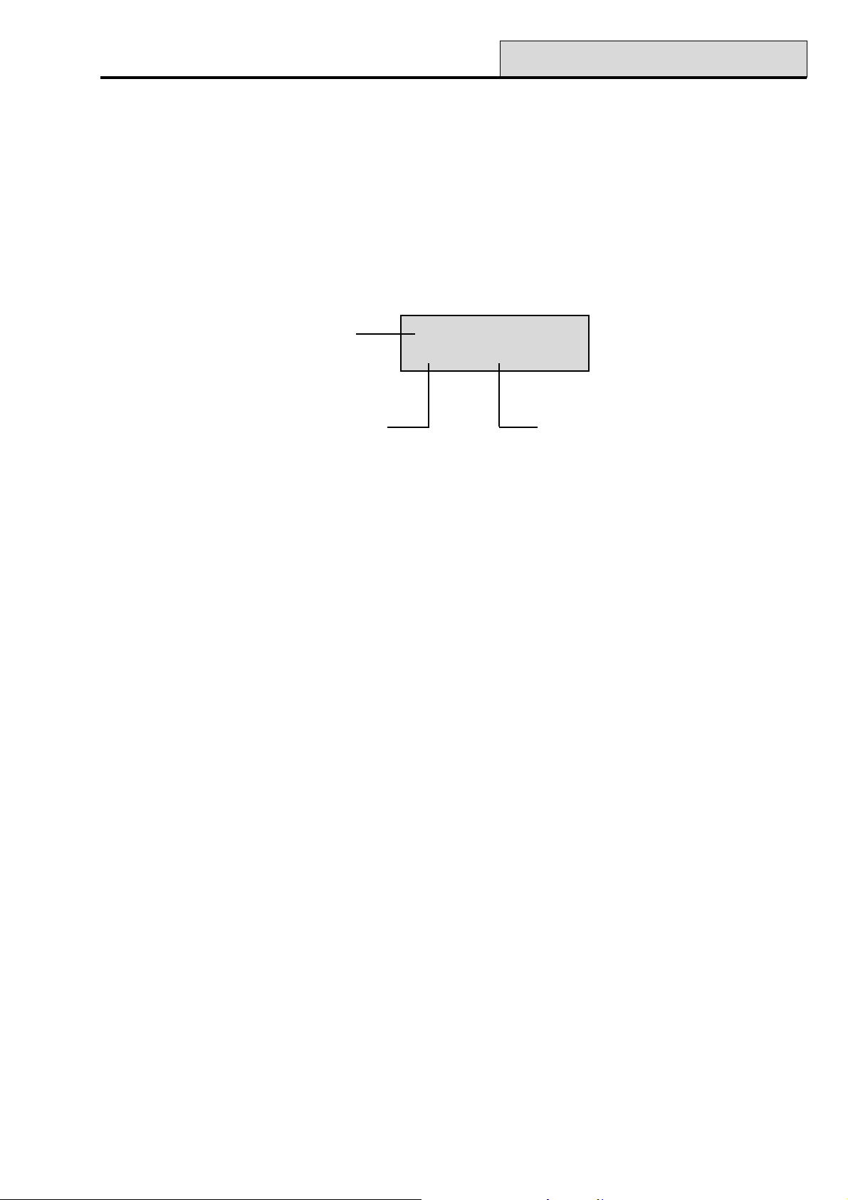
10:24 SUN 01 JAN
K10 L7
K = Keypad
AB Line
Keypad Address
18
Level of User Code
Page 25

Galaxy Programming Manual
NOTES:
1. Where two identical events occur within 1 second, only one is logged.
2. Only the first occurrences of high resistance and low resistance events on each day are logged.
Subsequent activations are ignored until midnight of the same day. This is to prevent the log
from being filled with high and low resistance activations from a faulty zone.
23 - System
The event log can be printed while accessing the Display Log option. Pressing the
event starts the printout from the displayed event and goes back to the first event. The esc key aborts the print
out.
NOTE: A serial printer must be connected to the Galaxy panel via a printer interface module or an RS232
interface module.
✴✴
✴ key while displaying an
✴✴
Option 23 – System (Galaxy 18, 60, 128, 500, 504 & 512)
This option provides a quick overview of the system configuration; two lines of information are displayed at a
time - the A and B keys are used to scroll through the entire list:
• Groups use the A and B keys to scroll through groups A1–8, B1–8, C1–8 and D1–8
• Group status U = Unset, S = Set, P = Part set and L = Locked-out for each of the groups
displayed;
NOTE: Enabling the Show Status option (refer to option 58 = KEYPADS) allows the group set status to
be displayed from the normal banner (when the system is set or unset) by pressing the ✴ and # keys
simultaneously.
• Type Galaxy 8, 18, 60, 128, 500, 504 or 512;
• Version version of software in Galaxy panel;
• RIOs fitted includes the on-board RIOs;
• Codes used includes the manager, engineer and remote codes;
• Keypads fitted 1–16 (Galaxy 8, 18, 60 & 128), 1–31 (Galaxy 500, 504 & 512);
• Comms modules 1-4 (Telecom, RS232, ISDN, Ethernet);
• Printer 0–1 (Printer Interface Module);
• Max Modules gives the number of Max/MicroMAX/MAX3 modules on the system;
• Panel location up to 16 characters of text entered in System Text parameter (option 51.15.2).
19
Page 26

24 - Print
Galaxy Programming Manual
Option 24 – Print (Quick Menu Option 5)
NOTE: A serial printer must be connected to the Galaxy panel via a printer interface module or an RS232
interface module.
This option allows one of the four listed options to be printed. Only information corresponding to the groups
assigned to the user is printed.
1. Codes – user number and name, level and groups assigned;
NOTE: only the manager can print out the user PINS; the Print Codes parameter (option 51.23) must be
enabled (default is disabled).
2. Zones – address, function, group (if group mode is enabled), status, descriptor (if assigned),
status of the chime, omit and part attributes, the RIO voltage and the zone resistance in Ohms;
3. Log – all events in the log, starting with the most recent and working backwards;
4. All – codes, zones and log details respectively.
The required option is selected by pressing the appropriate key 1-4. The printing begins immediately and can
be aborted by pressing esc.
20
Page 27

Galaxy Programming Manual
25 - Access Doors
Option 25 – Access Doors
NOTE: If the MAX mode has not been enabled (refer to option 63.2 = OPTIONS.MAX) the message No
Entries is displayed on entering this option.
Accessing this option when the MAX mode is enabled and there are MAX modules connected to the system
displays the address and descriptor details of the first MAX module on the system. Press the A and B keys to
view details of the other MAX modules on the system.
If there are no MAX modules attached to the system the message None Detected is displayed.
The MAX/MicroMAX/MAX3 log size mirrors the panel event log size. For example, the Galaxy 60 has a
MAX/MicroMAX/MAX3 log size of 300 events, and the Galaxy 500 has a MAX/MicroMAX/MAX3 log size
of 500 events. Full details of the MAX/MicroMAX/MAX3 log sizes for each panel type are given in Galaxy
Installation Manual, Appendix B, Panel Comparisons (part number II1-0030).
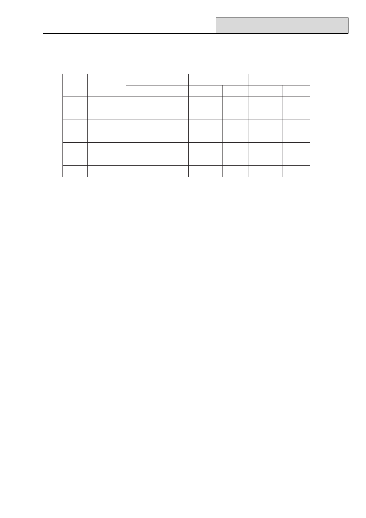
MAX/MicroMAX/MAX3 events are transmitted using Contact ID, SIA and Alarm Monitoring formats.
MAX/MicroMAX/MAX3 events transmitted are listed in the table that follows:
tnevEnoitpircseDedoCAIS
sseccA
detnarG
draCdilavnI
draC
detcejeR
detadilav
metsys
dnadetneserpdracdilaV
tonsahdetneserpdraC
otnodemmargorpneeb
tub,detneserpdracdilaV
nosaeremosrofdetcejer
GD124SGATXAMseYseY
DD224SGATXAMseYoN
KD224SGATXAMseYseY
DIC
edoC
reggirToNdoMDIresU
Table 3. Max/MicroMAX/MAX3 Events
Access Log Print and Store Option
The Access Doors (MAX/MicroMAX Log) is printed on-line and stored in the event memory.
The Access Door Log print displays in the format of the Event Log and allows information to be accessed.
The format is as follows:
HH:MM_XXXXXXXXXX_USR_NNN_UUUUUU_MYY_—_ (39 character display)
HH:MM = time in hour:minutes (5 characters). The date will be printed only at the beginning of every day,
that is midnight.
XXXXXXXXXX = access message (10 character) Valid, Invalid Vard, Reject Card
USR = User (3 characters)
NNN = User number to which MAX card is assigned (3 characters)
UUUUUU = User descriptor (6 characters)
M = MAX reader address (1 character)
YY = MAX physical address-M10, M24 etc (3 characters)
- (dash) = unused character slot
__ (underscore) = this represents a space and is not printed or displayed in the access log.
For example: A valid card read at MicroMAX/MAX3 30 from the card held by user 020, name Albert, at
13:48 would be:13:48 Valid USR 020 Albert M30 –
21
Page 28
25 - Access Doors (cont’d)
Galaxy Programming Manual
Access Door MicroMAX/MAX3 LED Status
When the access doors option is entered in engineering mode the MAX address can be displayed by pressing
the # key. This feature includes displaying the MicroMAX address using the MicroMAX LED format. This is
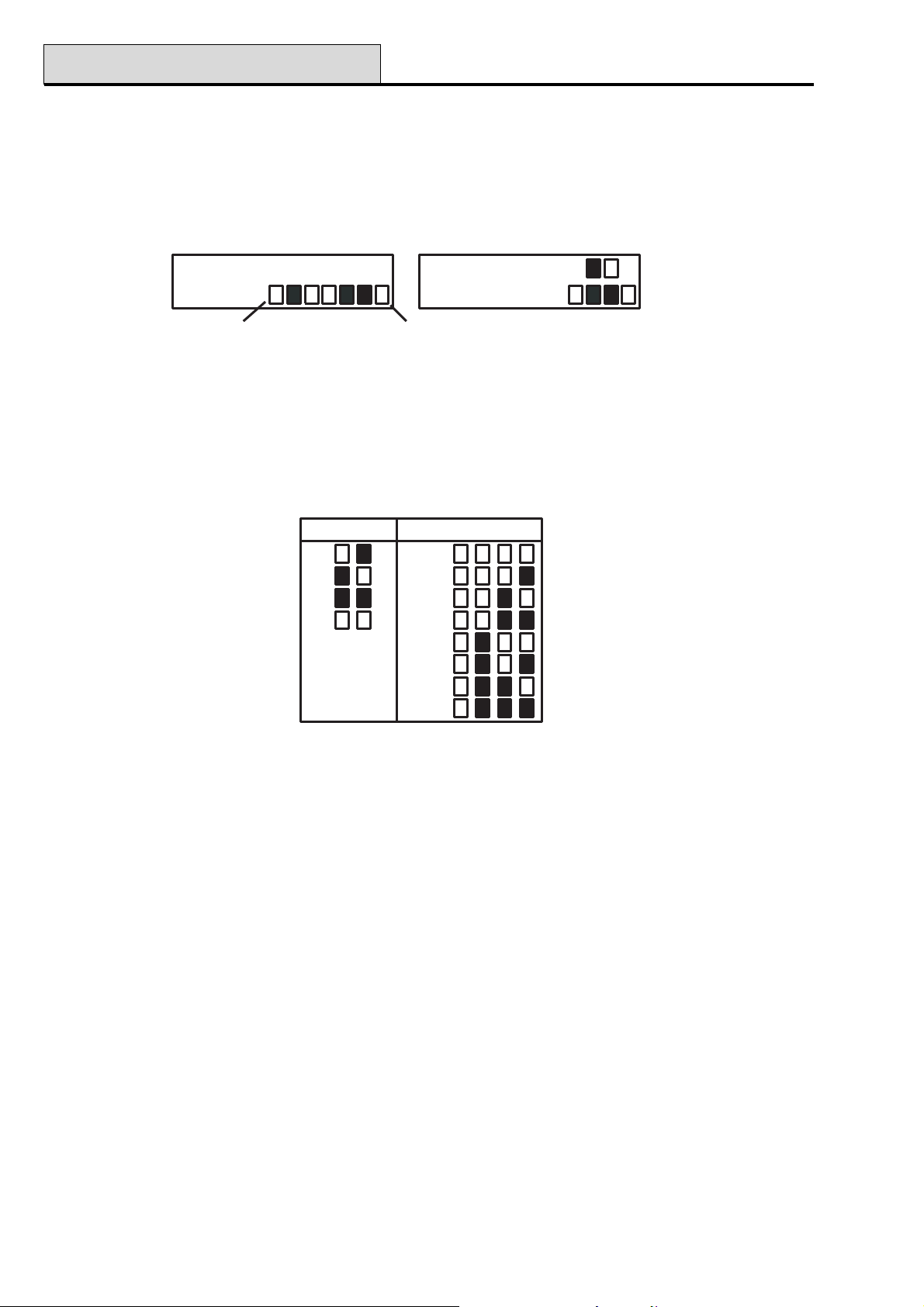
shown in the following Figure graphically for both a MAX and a MicroMAX address as 26.
MicroMAX LEDs Displayed
Top (unused)
Bottom
MAX LEDs Displayed
2 6M A X2 6M A X
Figure 1. LED Status
The line numbers are represented by the top row in MAX and blocks 2nd and 3rd from the top in the
MicroMAX and the address numbers are represented by the bottom row of blocks in the MAX and the four
bottom blocks in the MicroMAX. The top LED on the MicroMAX is always off in this mode.
The combinations are shown in the following Figure:-
Line No.
1
2
3
4
Module Address
0
1
2
3
4
5
6
7
Figure 2. Line Number/Module Address
Address
The first digit of the two digit number refers to the line that the module is connected to (line 1 on Galaxy 18 &
60, lines 1-2 on Galaxy 128, and lines 1–4 on the Galaxy 500, 504 & 512); the second digit is the physical
address number of the MAX module. For example, a MAX module displaying as 25 indicates that the module
is on line 2 and is addressed as 5.
Pressing the # key gives a graphic representation of the MAX address in a binary format. The top two boxes
on the top row indicate the line address; the bottom four boxes indicate the physical address.
Descriptor
The descriptor is a maximum of 16 characters entered in the MAX Parameters option (63.2.3)
Engineer Mode
On accessing the Access Doors option in engineering mode, each on-line MAX module displays its address
by lighting the appropriate LEDs. To help the engineer identify each of the MAX modules, the keypad displays a graphic representation of the MAX module address. By matching the (LED off) and (LED on)
image to the LEDs on the MAX, the engineer can identify each MAX module on the system.
22
Page 29
Galaxy Programming Manual
25 - Access Doors (cont’d)
MAX/MicroMAX/MAX3 Log
The MAX log stores proximity card events from the microMAX/MAX3 card readers.
To display the events in the MAX log, use the A or B keys to select the required MAX address then press the
ent key. The first event that occurred on the selected MAX is displayed along with details of the time, date
and MAX number.
To view the log press the A key to move forward in time through the events or the B key to move backwards.
Press the esc key to return to the MAX address display. To view the log of another MAX, use the A or B
key to select the required address. To escape form the Access Doors option press the esc key.
Time and date
of event
MAX user number
02:25 SUN OCT
USR032 Valid
Event type
23
Page 30

Galaxy Programming Manual
24
Page 31

Galaxy Programming Manual
31 - Walk Test
Section 6: Test Options
Option 31 – Walk Test (Quick Menu Option 6)
The Walk Test option offers two methods of testing zones.
1. Test All Zones: This option initiates a walk test that includes all zones that have the omit attribute
enabled (refer to option 52 = PROGRAM ZONES). When selected, the walk test starts immediately. The
message NO ENTRIES is displayed if all zones are non-omittable when selecting All Zones. Non-omittable
zones are not included in this test and remain active throughout the test.
2. Selected Zones: This test option allows the user to select any zones, irrespective of function type, for
walk testing. As many zones as necessary may be added to the list before starting the test. On entering this
option the details of the first zone are displayed. Each zone required for test can be selected using the A or B
keys or by entering the zone number. Press the # to toggle the test status of each zone in the Walk Test: the
test status of the zone changes to TEST if it is included in the test and # = TEST if it is not. When all the
required zones have been selected, press the ent key to start the walk test.
Press the ✴ key to include all zones in the Selected Zones walk test, without having to individually select the
zones. Once all zones are selected, the # key can be used to remove selected zones from the test.
NOTE: PA, PA Silent, PA Delay, PA Silent Delay and Fire are not included in the test when the ✴ key is
used to include all zones.
The response times of the zone circuits are reduced to 60 msecs for the duration of the walk test to facilitate
the detection of loose connections or damaged wiring.
Once the walk test has started, opening a zone (or a zone that is open at the start of the test) activates outputs
programmed as Entry/Exit Horn. If a single zone is open, the keypad displays the address and function of
the zone. If multiple zones are open, then the keypad indicates how many zones are open; the open zones can
be viewed by pressing the A or B keys.
NOTE: The Walk Test option does not display the status of the zones. If an open zone is included in the
walk test, the Entry/Exit Horn will activate as soon as the test is started and remains active until the
zone is closed.
While the walk test is active the message WALK TEST ACTIVE / ESC to abort is displayed; press the #
key to view all zones that have been walk tested so far. To return to the walk test press the # key again.
NOTE: RF zones will also record the signal strength in reduced gain mode.
Ending the Walk Test
To terminate the walk test, press the esc key. The test will terminate automatically if no zones are activated for
20 minutes.
The results of the test can be viewed by accessing the event log (refer to option 22 = DISPLAY LOG). The
start of the walk test is indicated by the display WALK TEST +; each zone that was tested is recorded (the
activation of each zone is recorded only once during the test — even if it was opened several times); the end
of the test is indicated by WALK TEST –.
25
Page 32

32 - Outputs
Galaxy Programming Manual
Option 32 – Outputs
Outputs are tested by function: for example, when 01 = BELLS is selected, then all outputs programmed as
Bells are activated. Refer to option 53 = PROGRAM OUTPUT for a full description of each output func-
tion.
On selecting the Outputs option, output function type 01 = BELLS is offered for selection. Press the A or B
keys to move to the required output function type. Alternatively, the function type number can be entered
directly, for example entering 13 selects SECURITY. To test the selected output function press the ent key.
The ent key can be used to toggle the function ON and OFF as required. To escape from the Outputs
option, press the esc key.
Users
User codes 5 & 6 only have access to 01 = BELLS and 02 = STROBE of the Output option. Only the
engineer has access to all the output types.
26
Page 33

Galaxy Programming Manual
41 - Time/Date
Section 7: Modify Options
Option 41 – Time/Date (Quick Menu Option 7)
Galaxy 8, 18, 60, 128, 500 & 504
The Time/Date option can be accessed and modified by level 6 codes, the engineer and the remote code.
Galaxy 512
The Time/Date option can be accessed by users, the engineer and the remote code, however, users can only
view the current time and date. Only the engineer and the remote code can modify the time and date. If any
groups are locked (refer to option 49 = Datelock), then the time and date cannot be modified.
Modifying the Time and Date
The Time/Date option allows the system time and date to be modified. On entering this option the display
prompts for selection A = TIME B = DATE. Press the A key to select the time option; this allows a new
time to be entered. The time must be a valid four digit number — in the 24 hour format (hh:mm). The entry, if
valid, will be accepted immediately and the display is returned to the selection screen. Press the B key to
select the date option; this allows a new date to be entered. The date must be a valid 6 digit number - in the
day, month and year format (dd/mm/yy). The date entry, if valid, will be accepted immediately and the display
is returned to the selection screen.
NOTE: The time and date can be modified when groups are set.
Adjusting the Clock Speed
Variations in the accuracy of the clock speed can be compensated by pressing the # key while the A = TIME
B = DATE selection screen in the Time/Date menu is displayed. The keypads prompts for the Adjustment/
Week, in seconds, to be entered; the range is 0 – 120 seconds. If the clock requires to gain time, enter the
required number of seconds. If the clock requires to lose time, enter the required number of seconds and
press the ✴ key; the ✴ retards the clock speed.
27
Page 34

42 - Codes
Galaxy Programming Manual
Option 42 – Codes (Quick Menu Option 8)
The Codes option is used to assign, modify and delete the codes that allow users to operate and access the
system. The Codes option is divided into three sub-menus:
1. User Codes — sub-divided into up to 10 menus (depending on panel used and whether the group and
MAX mode options are enabled) that determine all of the access information for users who are requiring
PINs. This option also assigns MAX details to user numbers;
2. PIN Warning — (Galaxy 128, 500, 504 & 512) determines the warning period given to users prior
to the programmed PIN Change date (refer to option 51.42 = PARAMETER.PIN Change);
3. MAX Users (V3 and earlier) — this option is only available if the MAX mode is enabled. The option
is subdivided into 2 menus that assign the MAX card to users who do not have a PIN assigned.
Programming Codes
1 = User Codes
1 = Modify Pin
2 = Modify Level
3 = Modify Name
4 = Time Zone
5 = Temp Code 00-99 days
6 = Modify Groups
(not G8)
7 = MAX Number
8 = MAX Function number of required menu option
9 = MAX Keypad
10 = Forgive
Antipassback
4, 5 or 6 digit pin
1 - 6
6 alpha-numeric characters
0 = Off
1 = Timer A
2 = Timer B
3 = Timer A+B
G18: 1-3
G60: 1-4
G128: 1-8
G500: 1-16
G504: 1-32
G512: 1-32
10 digit number on MAX card or fob
address of keypad that MAX function displays on
This function clears passback restrictions
2 = PIN Warning 1 - 28 days
3 = MAX Users
1 = MAX Number
2 = Groups G18: 1-3
10 digit number on the MAX card
G60: 1-4
G128: 1-8
G500: 1-16
G504: 1-32
G512: 1-32
Figure 3. Programming Codes
28
Page 35
Galaxy Programming Manual
42 - Codes (cont’d)
Default Codes
The Galaxy system provides 3 default codes: Manager, Engineer and Remote User. Refer to the following
Table:
yxalaGsedoCfo.oN
8 054321843322119401234505
81 00143218933221199012345001
06 0024321891332211991012345002
821 0524321842332211942012345052
005 0054321894332211994012345005
405 9994321799332211899012345999
215 9994321799332211#899012345999
reganaMreenignEetomeR
NIPtluafeD.oNresUNIPtluafeD.oNresUNIPtluafeD.oNresU
Table 4. Default Codes
Engineer Code
• The engineer code can only modify the engineer PIN; all other engineer User Code options are
fixed;
• The engineer code cannot assign, modify or delete the manager or user codes;
• On accessing engineering mode, any group that is set becomes inaccessible to the engineer. The
set groups cannot be assigned to zones, outputs and any other functions permitting group
allocation;
NOTE: If the Galaxy 8 is set, then the engineer cannot gain access to engineer mode.
• While engineer mode is accessed, all tampers are disabled, however, all constantly alert zone
types — PA zone types, 24 Hour, Security, Fire — remain active.
• The engineer banner is shown on all keypads while engineer mode is being accessed; the
message ENGINEER MODE is displayed;
(Galaxy 8, 18, 60, 128, 500 & 504)
The first entry of the engineer code activates a tamper alarm. The second entry of the code cancels this alarm
and accesses engineer mode.
NOTE: This dual code entry is only valid if the engineer does not have a # assigned against a PIN number.
Galaxy 60, 128, 500, 504 & 512
The Galaxy 512 engineer code is allocated a # is fixed by default. With the # assigned, entry to the engineer
mode must be authorised by a valid level 6 user (refer to option 48 = ENGINEER ACCESS). The engineer
code must then be entered within five minutes of the option being enabled. A single entry of the engineer code
directly accesses engineer mode, without activating an engineer tamper alarm; ENGINEER MODE is
displayed on the keypad. If the engineer code is not entered within the five minute period, the code is invalid
and an Access Denied message is displayed on the keypad. Once the engineer mode has been accessed,
there is no time limit on the period that the engineer can remain in the mode.
NOTE: Dual entry of the engineer code in a system requiring user authorisation does not give access to
engineer mode.
29
Page 36

42 - Codes (cont’d)
Galaxy Programming Manual
Escaping from Engineer Mode
1. Return to the engineer banner.
2. Enter the engineer code
3. Press the esc key
The Galaxy begins the exit engineer mode procedure by checking the integrity and security of the system:
• CHECKING FOR TAMPERS — if a Smart PSU is connected to the system, the panel calculates that the
standby battery connected to it is capable of operating the system for the required period (as entered in
the Standby Battery parameter — refer to option 51.37). The system then verifies that there are no
tamper conditions present on the panel, the modules or the zones.
• SYSTEM MODULES — if there are no tamper conditions the Galaxy checks the number of modules
connected to the system:
• If no modules have been added or removed, “ NO MODULES ADDED, ESC TO CONTINUE” is
displayed. Pressing esc returns the system to the normal banner.
• If modules have been removed they are reported as missing; the engineer is prompted to view the missing
modules and to remove them from the system by pressing the ✴; a warning is given before the module is
removed. Press the ent key to confirm the removal of the module. Once all missing modules are removed,
the Galaxy reports the previous and current number of modules connected to the system, before returning
to the normal banner.
• If modules have been added, the Galaxy reports the previous and current number of modules connected
to the system, before returning to the normal banner.
If the esc key is pressed at any time during the exit engineer mode procedure, the procedure is aborted and
the Galaxy returns to the engineer mode. This return may take several seconds to complete.
Galaxy 512
The engineer is prevented from exiting from engineer mode if a PA zone is open.
Manager Code
The manager is authorised to:
• program the User Code options of each of the user codes;
• allocate other codes to the manager level (6);
• modify the manager PIN — the manager PIN cannot be deleted — and assign the MAX features
to the code.
NOTE: Galaxy 18, 60, 128, 500 & 504 — the manager PIN can be reset to the default code (1234) by
the engineer and remote code using the Reset Mgr (Manager) parameter (refer to option 51.21).
The manager code defaults to group choice when groups are enabled. The manager is able to toggle
the group choice option on and off (using the ✴ key) as required.
30
Page 37
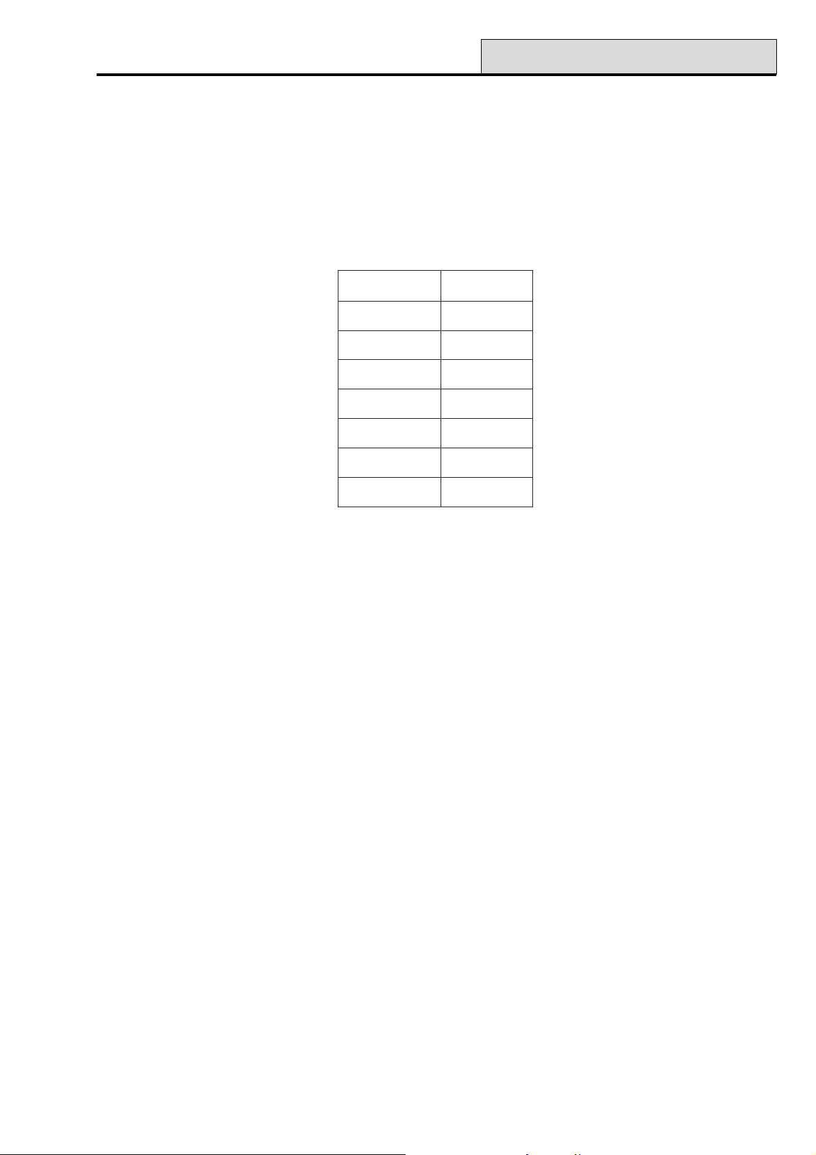
Galaxy Programming Manual
42 - Codes (cont’d)
Galaxy 8 & 18
The manager code defaults to accessing the quick menu (option 0 – 9). Refer to option 59 = Quick Menu.
To access the full menu, assign a ✴ to the manager in the Modify Level option.
Galaxy 60, 128, 500, 504 & 512
The manager code defaults to accessing the full menu (option 11 – 68). To access the quick menu (options 0 –
9), remove the ✴ assigned to the manager in the Modify Level option.
lenaPlortnoCsedoCresU
8G05
81G001
06G002
821G052
005G005
405G999
215G999
Table 5. Control Panel/Codes
Programming Codes
1 = User Codes
Enter the Codes option; 1=User Codes is displayed. Press the ent key; details of the first user (User 001)
are displayed. Each of the users can be displayed using the A and B keys, or a specific user can be selected
by entering the required user number, for example 023, 069. When the required code is displayed, press the
ent key to select the user codes modification options; 1=Modify PIN is displayed. The available modification
options can be viewed by pressing the A or B keys; press the ent key to select the required option. The
options are detailed in the following paragraphs:
31
Page 38

42 - Codes (cont’d)
1 = Modify PIN
The PIN identifies each user to the Galaxy panel and permits the user to operate the system. The Modify
PIN option allows a PIN to be assigned to the user or an existing PIN to be modified. The PIN must be a
four, five or six digit number that is unique to the system. If a duplicate PIN is assigned, the message
INVALID SELECTION is displayed; the PIN is not assigned to the user. As each digits is entered it ap-
pears on the lower line of the display. Pressing the ✴ key erases the last digit displayed; continued pressing of
the ✴ key will erase all of the digits. When the correct PIN has been assigned press the ent key to accept the
programming and, if a MAX No. is assigned the display will prompt: delete max no. A = YES, B = NO
and return to the previous menu level. When a PIN has been assigned to a user number, a solid box (■) is
displayed on the top line of the user number details screen.
Deleting a PIN
Existing PIN entries can be completely erased by using the ✴ key instead of a digit entry. When there is no
PIN assigned to a user number a hollow square () is displayed on the top line of the user number details
screen.
Assigning Dual Codes
Galaxy Programming Manual
To program a user code as a Dual Code press the # key while the Modify PIN option is selected. The #
displays at the start of the assigned user PIN (#1314). When a PIN has been assigned as a dual code 2 solid
boxes (■ ■) are displayed on the top line of the user number details screen.
NOTE: The Master manager code can not be assigned as dual.
Dual Codes Operation (Galaxy 60, 128, 500, 504 & 512)
Entry of a single dual code can not gain access to the menu, set or unset the system. The message NO ACCESS – ADDITIONAL CODE is displayed. A second dual code must be entered within 60 seconds of the
first dual code to access the menu, set or unset the system. Dual codes can be different levels, the highest level
entered is granted access to the system — whether it is entered first or second.
A single entry of a dual code - without a second dual code entry within 60 seconds - is recorded in the event
log as an Illegal Code; all outputs programmed as Illegal Code are activated. 2 = Modify Level
Dual Focus (V4 and above)
If a MAX number for the same user has a # assigned the dual function only works between the PIN and the
MAX card of the same user.
2=Modify Level
Each user is assigned an access level which determines the menu options available to the user. The programmable levels are from 0 - 6; 7 is assigned to the engineer level — this is fixed and cannot be assigned to user
codes; 8 is assigned to the remote code. This is fixed and cannot be assigned to the engineer or user codes,
keypad (E) only.
On selecting this option, enter the level to be assigned to the user and press the ent key to accept the programming and return to the previous menu level.
32
Page 39
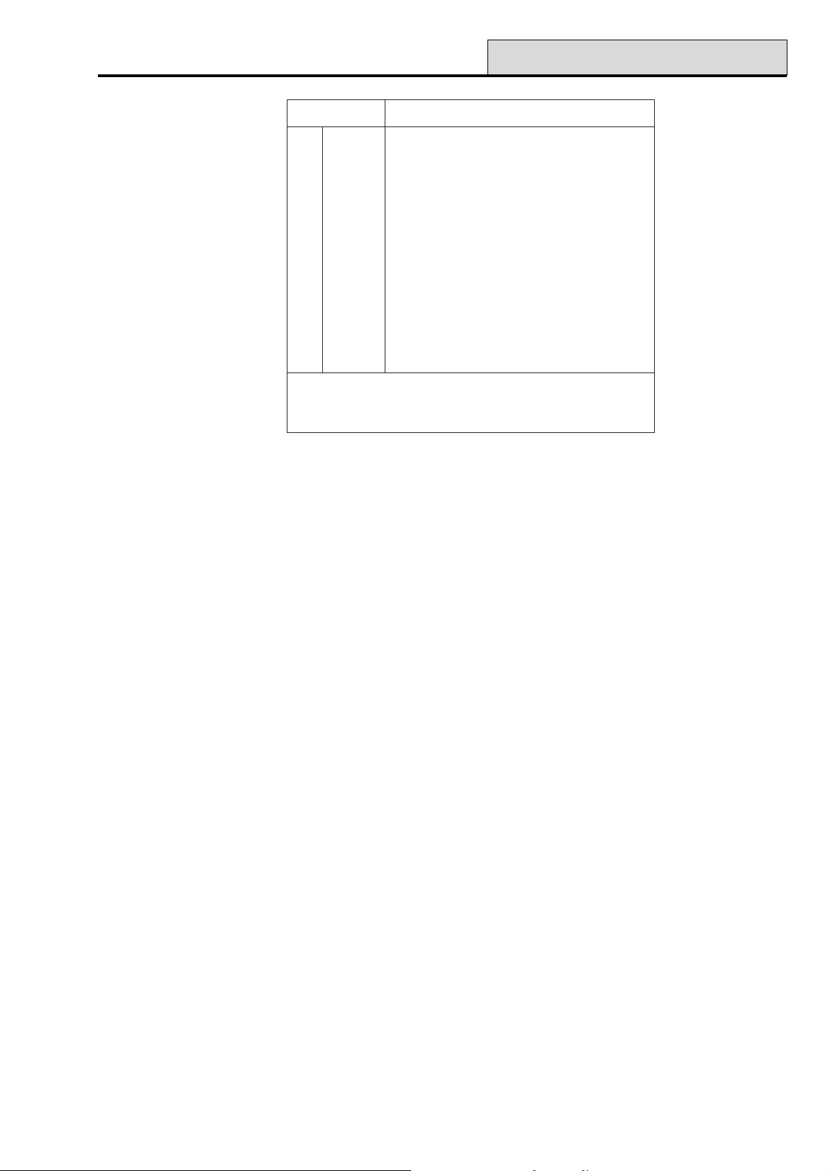
Galaxy Programming Manual
leveLytilibaliavAsseccA
†0drauGnoitporehtoon–yromemtneveotnideretnE
†1renaelCmetsysehttesylnonaC
2rekateraCmetsysehttesnudnatesylnonaC
3sresU91-11snoitpouneM
4sresU92-11snoitpouneM
5sresU93-11snoitpouneM
‡6reganaM94-11snoitpouneM
‡7reenignE86-11snoitpouneM
‡8etomeR86-11snoitpouneM
42 - Codes (cont’d)
†
‡
snoitcnufunemotsseccaoN
sedoceerhttsaleht(sedocetomerdnareenigne,reganamehT
.demmargorperebtonnachcihwsleveldexifevah)metsysehtno
Table 6. User Access Levels
Duress Code (Galaxy 18, 60, 128, 500, 504 & 512)
If the # key is pressed while the Modify Level option is accessed, then the current user code is assigned as a
Duress Code. Entry of a Duress Code at any time activates any output programmed as Duress (refer to
option 53 = OUTPUTS). There is no limit to the number of codes that can be assigned as Duress Codes.
Entry of any valid user code followed by ## is also a duress code.
Quick Menu
All of the user codes default to the quick menu. This menu is made up of a selection of ten options
(0 – 9) from the full menu options 11 – 68. Access to the quick menu is controlled by the user code level.
Any user can be upgraded from the quick menu to the full menu by assigning a ✴ to the user while the
Modify Level option is accessed. Therefore a user with level ✴5 would have access to the full menu from
options 11 – 39. No code can access both menus.
The engineer can reprogram the options contained in the quick menu (refer to option 59 = QUICK MENU).
NOTE: The manager code defaults to the quick menu on the Galaxy 8 and 18 but defaults to the full menu
on the Galaxy 60, 128, 500, 504 & 512.
Galaxy 60, 128, 500, 504 & 512
The engineer can determine the menu option access level (refer to option 68 = MENU ACCESS); this allows
users to access menu options that their code levels are not, by default, authorised to access.
NOTE: Users can only allocate codes up to the level that they have been assigned. A level 4 user cannot
assign a user code as level 5.
33
Page 40

42 - Codes (cont’d)
Galaxy Programming Manual
3 = Modify Name
This option allows a name to be assigned to the user (maximum 6 characters). Each of the user codes default
to the name USER. The engineer (ENG) and manager (MGR) are fixed and cannot be reprogrammed. On
selecting the Modify Name option, a section of the alpha-numeric characters that can be assigned to the user
name is displayed on the bottom line of the keypad; the cursor flashes on the letter L. Press the ✴ key to
erase the characters of the default or previous name. When the previous name has been erased, use the A or
B keys to move the cursor to the first character of the name and press the ent key; the selected character
appears on the top line. Continue this process until the name is completed.
The # key moves between upper and lower case characters and the system library. The alpha-numeric char-
acters and library words can be selected by entering the character or word reference number (refer to Ap-
pendix B — Library) or by pressing the A or B keys.
NOTE: The Galaxy 8 does not have a library.
When the user name is completed, press the esc key to accept the programming and return to the previous
menu level.
4 = Time Zone (Galaxy 18, 60, 128, 500, 504 & 512)
The Time Zone option allows the user access to be restricted to operate only within the periods programmed
in Timer A and/or Timer B (refer to option 65 = TIMERS).
On selecting this option enter the number (0 – 3) of the Time Zone to be assigned to the user and press the
ent key to accept the selection and return to the previous menu level.
noitceleSremiTnoitcirtseRsedoC
0FFO
)tluafeD(
1AremiTneewtebevitareponierasdracdnasedoC
.emitFFOdnaNOAremiTeht
2BremiTneewtebevitareponierasdracdnasedoC
.emitFFOdnaNOBremiTeht
3B+AremiTneewtebevitareponierasdracdnasedoC
.lanoitareposyawlaerasdracdnasedoC
.emitFFOdnaNOBdnaAremiTeht
Table 7. Time Zone Restrictions for Users
Codes or cards if programmed do not operate during the assigned time zone (ON to OFF). The times assigned to Timer A and Timer B can be viewed using option 45.3 = TIMER CONTROL.View.
If a user that has been assigned to 1=Timer A, 2=Timer B or 3=Timer A+B attempts access outwith the
assigned times, then an Illegal Code event is recorded in the log and any outputs programmed as Illegal
Code are activated.
34
Page 41

Galaxy Programming Manual
5 = Temporary Codes (Galaxy 128, 500, 504 & 512)
Temporary Codes allows a PIN to be temporarily allocated to a user. On selecting this option, enter the
number of days (0 – 99) that the code is to remain active. The default setting of 0 indicates that the code is
permanent. A temporary code expires and is removed from the codes list at midnight after the assigned
number of days. A code that has been assigned as a Temporary Code is indicated on the user code display
by a ^ between the user number and the user name, for example 001^USER.
NOTE: The manager, engineer, or remote codes cannot be assigned as Temporary Codes.
PIN Change (Galaxy 128, 500, 504 & 512)
If a user is assigned the PIN Change feature in the Temporary Code option, the user must assign a new PIN
after a predetermined period — refer to option 51.42 = PARAMETERS.PIN Change — otherwise the
user PIN expires and is no longer operational.
To program a user code to prompt for a PIN change select the Temporary Code and press the ✴ key
instead of entering a number of days for a temporary code; press the ent key to accept the programming and
return to the previous menu level. A code that has been assigned as a PIN Change code is indicated on the
used code display with a ✴ between the user number and the user name, for example 001
Manager, Engineer, or Remote codes cannot be assigned as PIN Change Codes.
42 - Codes (cont’d)
✴✴
✴USER. The
✴✴
If the value entered in the PIN Change parameter is 0 then the code is assigned as a permanent PIN — a
warning message is briefly displayed to indicate that a Pin Change will not be requested. However, if PIN
Change is within the range 1 – 12, then the number entered is number of months after which the code must be
changed, otherwise it expires.
NOTE: The PIN expires on the first day of the following month.
A notification (1 – 28 days) that the PIN requires to be changed can be assigned using the PIN Warning
option (refer to option 42.2); this prompts the user to assign a new code whenever the expiring code is entered - except when the system is unsetting - for the number of days in the PIN Warning before the day the
PIN expires. The new PIN must be six digits and must be different from any current PIN including the user’s
existing one. The new PIN must be re-entered and, if confirmed, the user is returned to the banner. If the esc
key is pressed or the new PIN entered is invalid, the user may continue to use the panel as normal; the next
entry of the PIN will prompt for the PIN change.
NOTE: If the user has not assigned a new PIN by the end of the PIN Warning period, then the code is
erased on the next unsetting of the system.
6 = Modify Group (Galaxy 18, 60, 128, 500, 504 & 512)
This option determines the system groups that the user has access to and operational control over. The
Modify Groups option is only available when the group mode is enabled (Galaxy 500, 504 & 512).
The Galaxy 500, 504 and 512 have more than 8 groups; these are displayed on the keypad in blocks of eight
groups. Press A or B keys to display each of the group blocks.
Press keys 1 – 8 to assign the relevant groups in each block to the user.
Code has been enabled (refer to option 63.1 = OPTIONS.Groups); the system defaults to groups disabled.
35
Page 42

42 - Codes (cont’d)
Galaxy Programming Manual
On selecting the Modify Groups option, the groups currently allocated to the user are displayed. All user
default to group 1. Pressing the group number toggles the group assigned to the user; pressing 2 and 3 assign
groups 2 and 3 to the user; pressing 1 (when group 1 is already assigned) removes group 1 from the user
code. To assign group choice to the user, press the ✴ key. When the required groups have been assigned to
the user, press the ent key to accept the programming and return to the previous menu level.
Galaxy 500, 504 & 512
The Galaxy 500, 504 and 512 have more than 8 groups; these are displayed on the keypad in blocks of eight
groups. Press the A or B key to display each of the group blocks.
Press keys 1 – 8 to assign the relevant groups in each block to the user.
kcolBpuorGspuorGlacisyhP
8-1A8-1
8-1B61-9
8-1C42-71
8-1D23-52
Table 8. Groups
Group Options
Single Group A user can be assigned to any single group. In this case the level 2 and above user can
only access, set and unset the single group.
Multiple Groups Users can be allocated to more than one group in which case access and operation is
collective; the user cannot choose to operate on a single or combination of the assigned
groups.
Group Choice Users can be allocated more than one group but also have the choice of which of the
allocated groups to view , set or unset. Pressing the ✴ key while assigning groups to the
user assigns the group choice feature.
NOTES:
1. The manager, engineer and remote codes have fixed access to all system groups; this cannot be
reprogrammed
2. The manager, engineer and remote codes are assigned group choice by default. The manager can
have the group choice feature removed; the engineer and remote codes have fixed group choice.
3. Users authorised to access Option 42 = CODES, can only assign the groups that have been
assigned to their user code; A user who does not have access to group 4, cannot assign group 4 to
another user code.
7 = MAX Number
The MAX Number contains one of the following:
• the 10 digit number etched onto the MicroMAX/MAX
3
card/fob/tag
• a number generated by the RF RIO identifying an RF Keyfob button
• the decrypted code of cards/tags self learned into the system for use with the keyprox.
These numbers identify the card/tag/fob to the system and references it to the user it has been assigned to.
36
Page 43

Galaxy Programming Manual
Each MAX Number defaults to 0000000000 (ten zero’s):
To enter the required number:
1. press and hold the B key until the zeros are deleted;
2. enter the unique 10 digit number laser etched onto the MAX/MicroMAX card/Fob tag or
enter the unique RF keyfob button identifier generated by the RF RIO (refer to RF RIO programming
instructions II1-0076 for details) or
press the A and 1 keys simultaneously of the KeyProx and present the card/fob to the KeyProx reader
within 5 seconds. The decrypted number in the card will be self learned onto the Galaxy panel and
displayed on the KeyProx.
3. press the ent key to save the programming and return to the previous menu level.
NOTE: A MAX number can be assigned to a user code that does not have a PIN allocated to it. All other
options assigned to this user are valid for the card/fob/tag button programmed.
8 = MAX Function
42 - Codes (cont’d)
The card/fob/tag/button can be assigned a single menu option. The user must be authorised to access the
menu option assigned to the MAX - either by the user level assigned or menu option 68 = Menu Access.
The default option is Not Used. A new option is assigned by pressing the A or B key until the required
option is displayed or by entering the option number directly and then pressing the ent to accept the selection.
9 = MAX Keypad
The menu option assigned to the MAX card can be limited to operate on a single keypad. On selecting this
option the display shows ✴✴, indicating that a keypad has not been specified. To specify a keypad, press the
# key. The address of the first keypad on the system is displayed. Use the A or B key to select the required
keypad and press the ent key to accept the selection.
NOTE: The address of the keypad that is currently being used is indicated by a black square flashing over
the first digit of the keypad address.
“Card-Held” Operation
The programmed MAX function is activated when either,
• the card/fob /tag is held continuously in front of the MAX/MicroMAX/KeyProx reader for 3 seconds
or
• the programmed RF keyfob button is pressed. It should be noted that if button 1 of the RF keyfob is
programmed as a setting function, button 2 will automatically become the unset action, as long as
button 2 has been programmed for MAX operation on the RF RIO.
If using a MAX/MicroMAX or KeyProx the reader or KeyProx must be assigned a common group to the
user. The keypad specified in option 9 = MAX Keypad displays the assigned MAX function.
Assigning Dual Functions to MAX Numbers (V4 and above)
If a card has a # assigned to the number, then any card-held function will only work in conjunction with the
PIN from the same user, provided that the PIN has a # assigned also. The Dual Focus function will work in
either order, but if the card is presented first, it will simply enable the PIN to gain access to the normal menu
(see option 42 = Codes for programming).
37
Page 44

42 - Codes (cont’d)
If a user’s card number is assigned a *, then the card becomes Dual access. This means that it will not open
the door on its own; it needs another PIN or card as well. If the PIN belonging to the same user has a #
assigned, then that PIN must be entered first before access will be granted to that card.
If the PIN has no # assigned, then the card will work only in conjunction with any other Dual Access card that
shares one or more groups (see option 42 = Codes for programming).
10 = Forgive Antipassback (V4 and above)
This function if selected clears all antipassback restrictions for the selected user.
Galaxy Programming Manual
2 = PIN Warning (Galaxy 128, 500, 504 & 512)
This option determines the number of days notification before the PIN Change expiry date (refer to option
51.42 = PARAMETERS.PIN Change) that the user is prompted to assign new code on entry of the expir-
ing PIN. The default period is 28 days, with a programmable range of 1 – 28. If the user does not assign a
new code by the end of the PIN Warning period, then the code is erased on the next unsetting of the system.
NOTE: The PIN Warning ends on the last day of the month, the PIN expires on the first day of the
following month.
3 = MAX Users
Note: This option does not apply to V4 and above software.
This option is used to assign additional MAX users to the system without allocating PINs; MAX users are
only authorised to operate the Access Control functions of the MAX modules.
Enter the Codes option and select 3=MAX Users. Press the ent key; the first MAX user number (User 501)
is displayed. Each of the users can be displayed using the A and B keys, or a specific user can be selected by
entering the required user number, for example 223, 469. When the required code is displayed, press the ent
key; the 1 = MAX Number option is displayed.
1 = MAX Number
The MAX number assigned to the MAX user identifies the MAX card to the system and references it to the
MAX user.
Each MAX Number defaults to 0000000000 (ten zero’s):
1. press and hold the B key until the zeros are deleted;
2. enter the unique 10 digit number laser etched onto the MAX card;
3. press the ent key to save the programming and return to the previous menu level.
When a MAX number has been assigned to a MAX user number, a solid box (■) is displayed on the top line
of the MAX user number details screen.
2 = Groups
This option assigns group access to the MAX user. The MAX user must be assigned a group that is common
to the MAX module to permit the access control functions to operate. If the MAX user does not have access
to the group assigned to the module, then the access control functions are denied. The Modify Groups option
is only available when the group mode has been enabled (refer to option
63.1 = OPTIONS.Groups); the system defaults to groups disabled.
38
Page 45

Galaxy Programming Manual
On selecting the Modify Groups option, the groups currently allocated to the user are displayed. All user
default to group 1. Pressing the group number toggles the group assigned to the user; pressing 2 and 3 assign
groups 2 and 3 to the user; pressing 1 (when group 1 is already assigned) removes group 1 from the user
code; press the ent key to accept the programming and return to the previous menu level.
Galaxy 500, 504 & 512
The Galaxy 500, 504 and 512 have more than 8 groups; these are displayed on the keypad in blocks of eight
groups. Press A or B keys to display each of the group blocks.
Press keys 1 – 8 to assign the relevant groups in each block to the user.
43 - Summer/44 - Trace
Option 43 – Summer (Quick Menu Option 9)
The Daylight Savings Time is in accordance with European standards. The Daylight Savings time is described
as follows:
On the first day of each year, the British Summer Time (BST) Start date is set to the last Sunday in March
and the End date is set to the last Sunday in October.
The operation of the Summer option is as follows: at 01:00 hours (GMT) on the Start date, the system
clock advances to 02:00 hours (DST); at 02:00 hours (DST) on the End date, the system clock goes back to
01:00 hours (GMT).
NOTE: The time always changes with reference to GMT. For example, Italy, which is +1 hour would be:
Last Sunday in March - 02.00 to 03.00
Last Sunday in October – 03.00 to 02.00
The Start and End dates can be reprogrammed by authorised user codes. Press the A key to modify the
Start date or the B key select the End date; the new date must be a valid 4 digit number - in the day/month
format (dd/mm).
Galaxy 512
The Summer option can only be modified by the engineer or remote codes.
Option 44 – Trace (Galaxy 18, 60, 128, 500, 504 & 512)
This option provides a record of the most recent alarm activation. The Trace option records the details of the
setting and unsetting of the system immediately before and after the alarm activation and the first 5 events
occurring during the alarm activation. This information is maintained in the trace until the next alarm activation.
On entering the option pressing the A and B keys steps through each of the 7 trace entries.
Pressing the # key while viewing the Trace option displays additional information about certain events — user
events reveal the keypad, user level and current group; alarm events reveal the zone descriptor if programmed.
The currently display trace can be printed out by pressing the ✴ key; pressing the esc key aborts the print-
out.
NOTE: A serial printer must be connected to the Galaxy panel via a printer interface module or an RS232
interface module.
39
Page 46

45 - Timer Control
Galaxy Programming Manual
Group Mode
If group mode is enabled (refer to option 63 = OPTIONS), there is a separate trace for the most recent
alarm activation in each of the groups. On selecting the Trace option, a user with group choice (refer to option
42 = CODES) can view the trace of the assigning groups; press the number of the group to be displayed —
the N below the selected group changes to a Y — and then press the ent key.
If more than one group is selected, or the user does not have group choice, then the trace for the group with
the most recent alarm activation is displayed.
Option 45 – Timer Control (Galaxy 18, 60, 128, 500, 504 & 512)
1 = View
This option allows the programmed times in each of the Timers to be viewed:
1. Timer A;
2. Timer B;
3. Autoset (Galaxy 18, 60, 128, 500, 504 & 512);
4. Lockout (Galaxy 512).
Use the A and B keys to scroll through each of the programmed times.
NOTE: The programmed times cannot be modified using this option.
All of the programmed timers - Timer A, Timer B, Autoset and Timelock - can be printed out using option
57.11 = SYSTEM PRINT.Timers.
2 = Holidays
This function allows up to ten holiday periods to be allocated. A Start and End date is entered for each
holiday period using the 1 = Modify Dates option, and the groups that are affected by the programmed
holiday periods are assigned using the 2 = Assign Groups function. The operation of all timers for the assigned groups is suspended during these dates; the last operation of the Timers before the start date remains
in operation until the first operation after the end date. For example, a code which has been allocated the
Timer A period in the CODES option (42.1.4.1) will be inoperative during the programmed holiday period if
the Timer A is in the On time when the holidays starts.
1 = Modify Dates
On selecting this option, the Start and End dates for holiday period 1 are displayed; an arrow (>) points to
the Start date. If no dates have been entered for this period, then the display shows ✴✴/✴✴. To program
the Start date, press the ent key; the date display changes to >DD/MM<; enter a valid four digit number
and press the ent key to accept the selection; the year is not required, only the day and months (dd/mm).
Press the # key to move to the end date and follow the procedure for programming the Start date. The #
key toggles between the Start and End dates for each holiday; the arrow (>) indicates which date is currently
selected.
To remove a programmed date, press the ✴ key. The date display returns to ✴✴/✴✴.
Use the A or B key to move between the different holiday periods or enter the number of the holiday period
(1 – 10) to be programmed.
40
Page 47

Galaxy Programming Manual
Galaxy 60, 128, 500 & 504
The holiday periods can be programmed by a valid user.
Galaxy 512
The holiday periods can only be programmed by the engineer. Users can access this option, however, they
can only view the programmed holiday dates.
2 = Assign Groups
This function determines which of the groups are affected by the programmed holiday periods.
On selecting the Assign Groups option, the groups currently assigned to the programmed holiday periods are
indicated by a Y below the group; an N is displayed below the unassigned groups. All groups default to Y.
Pressing the group number toggles the group status. When the required groups have been assigned to the
holidays, press the ent key to accept the programming and return to the previous menu level.
Galaxy 512
The Galaxy 500, 504 and 512 have more than 8 groups; these are displayed on the keypad in blocks of eight
groups. Press A or B keys to display each of the group blocks.
45 - Timer Control (cont’d)
Press keys 1 – 8 to assign the relevant groups in each block to the user.
3 = Timers (Galaxy 18, 60, 128, 500 & 504)
This option allows Timer A and Timer B to be switched on and off as required. If a Timer is set to off, the
operation of the Timer is suspended; this option cannot be used to alter the programmed times. Both timers
default to 0 = Off. To switch the timers on, select the required timer and change the setting to 1 =On.
The Timer Status can also be altered through menu option 65.1 by the engineer only.
Galaxy 512
This option is not available on the Galaxy 512.
4 = Early Open (Galaxy 512)
If the Early Open option (45.4.2) is enabled, the Lockout OFF time (refer to option 65 = TIMERS) for
the following day is brought forward by the number of minutes (0 – 240) programmed in parameter 44 =
Early Open. This allows the system to be manually unset earlier than normal.
1 = Early Times
This function displays the time that the system can be manually unset on the following day; this time is the
Lockout OFF Time minus the Early Open period and is displayed in the 24 hour format.
If groups have been enabled, the early opening time for each of the groups enabled for early opening in the
Early Open option can be viewed by pressing the A or B keys
This function only displays the early time if the Early Open option is enabled; if this option is disabled or if no
groups have been enabled, the message NO ENTRIES is displayed.
41
Page 48

45 - Timer Control (cont’d)
2 = Early Open
Level 6 Users and Engineer when Groups are Disabled
If groups have not been enabled on the system, the programming of the Early Open option is identical for
Level 6 users and the engineer; the option permits early opening to be disabled or enabled:
0 = Disabled (default) — early opening not permitted;
1 = Enabled — early opening permitted.
Select the required status and press the ent key to accept the programming and return to the previous menu.
Engineer Mode with Groups Enabled
If groups have been enabled (option 63 = OPTIONS + early open permitted), then the groups can be
individually enabled to permit early opening.
On selecting the option, the early opening status of the groups is displayed; early opening enabled is indicated
by a Y below the group; an N is displayed below the groups that are not programmed to open early. All
groups default to N.
Galaxy Programming Manual
NOTE: Only the engineer can enable early opening for individual groups, but global enable must be done
first.
5 = Late Work
The Late Work option — if programmed as 1 = ON — authorises an Autoset Extension in advance of the
prewarning period (refer to option 65.3 = TIMERS.Autoset);
NOTE: Additional extensions can be authorised by entry of a valid code during the subsequent autoset
prewarning periods.
6 = Weekend Work (Galaxy 504 & 512)
The Weekend Work option allows a valid user code to authorise the system to unset at the weekend. If the
Weekend Day is programmed other than 0 = OFF (default), on the next occurrence of the programmed
Weekend Day, the Timers adopt the times they have on the assigned Pattern day. For example, this
allows a Sunday to use the Autoset and Lockout Timers of a Monday.
NOTE: Parameter 41 = Weekend Work must be enabled (default is Disabled) to allow the Pattern Day
option to be programmed by the engineer and the Weekend Day to be selected by the user.
On selecting this option, 1 = Program Days is displayed. Press the ent key; 1 = Weekend Day is dis-
played. Press ent to select this option, or the A or B keys to move between the available options.
42
Page 49

Galaxy Programming Manual
1 = Weekend Day
On selecting this option the programmed Weekend Day is displayed; the default is 0 = OFF. Use the A or B
keys to select the required day or days and press the ent key to accept the programming and return to the
previous menu level:
0 = OFF
1=SAT
2 = SUN
3 = BOTH (Saturday and Sunday)
The selected Weekend Day remains active for one occurrence only. The Weekend Day returns to the
default of OFF immediately following the assigned day. The Weekend Day must be allocated each time the
function is required.
2 = Pattern Day
The Pattern Day can only be allocated by the engineer. This option determines the programmed timers that
are effective when the Weekend Day option is selected by the user; the timers of the selected Pattern Day
are adopted by the days selected for weekend work.
45 - Timer Control (cont’d)
On selecting this option the programmed Pattern Day is displayed; the default is 1 = MON. Use the A or B
keys to select the required day or days and press the ent key to accept the programming and return to the
previous menu level:
1 = MON
2 = TUE
3 = WED
4 = THU
5 = FRI
43
Page 50

46 - Group Omit
Galaxy Programming Manual
Option 46 – Group Omit (Galaxy 18, 60, 128, 500 & 504)
This option allows a level 6 user code to block omit all the omittable zones that are open at the end of the
confirm time in a group or multiple groups. All zones in the required groups that have the omit attribute enabled (refer to option 52.4 = PROGRAM ZONES.Omit) are omitted when this option is selected. Groups
can be omitted and reinstated without setting and unsetting the system.
On selecting the Group Omit Option the groups assigned to the user code and keypad are displayed as well
as the omit status of each group (Y below the group indicates that it is omitted, N indicates that it is not omit-
ted). To omit a group, press the required key. The letter beneath the group number changes from N to Y. To
reinstate the group press the key to toggle from Y to N.
NOTE: The level 6 user must have group choice to enter Group Omit.
NOTE: The zones in the selected groups are omitted from the system as soon as the group is selected.
On returning to the banner (normal or engineer) the keypad displays the message ZONES OMITTED.
Omitted zones remain omitted for one set period only or until they are manually reinstated to the system.
Galaxy 18, 60, 128, 500 & 504
Outputs programmed as Zone Omit (mode programmed as reflex) are activated as soon as the zone is
omitted and remains active until the zone is reinstated. If the output mode is programmed as latch, then the
Zone Omit outputs activate when the system is set and remain active until the system is unset — reinstating
the omitted zones.
44
Page 51

Galaxy Programming Manual
47 - Remote Access
Option 47 – Remote Access
1. Service
This option enables level six users to control the access mode of the Galaxy Gold remote servicing software.
There are several options available for increased flexibility and security.
NOTE: This option is only available when the Manager Authorise option has been enabled (refer to
option 56.1.12 = COMMUNICATIONS. Telecom.Remote Access). If the option is not
enabled, the keypad displays NO ACCESS - OPTION DISABLED.
0 = Telecoms
0 = Direct Access
On selecting this option, a 40 minute access period is enabled on the Galaxy panel; Galaxy Gold software can
directly access the system during this period. Once access to the panel has been gained, it can maintained
indefinitely; there is no maximum duration. On terminating the Galaxy Gold connection to the panel, the access
period remains valid for an additional 15 minutes.
1 – 5 = Call Back 1 – 5
A maximum of five numbers can be preprogrammed by the engineer (refer to option 56.1.12 =
COMMUNICATIONS.Telecom.Remote Access). On selecting one of the numbers (1 – 5) followed by
the ent key, the Galaxy panel dials out to the preprogrammed telephone number associated with the Call
Back number.
If the number selected does not have a preprogrammed telephone number, the system prompts for a number 1
to be entered. Enter the required telephone number and press the ent key; the panel then dials out to the
telephone number entered.
NOTE: The PC that the panel is dialling to must have Galaxy Gold running in the Waiting for Call-Back
mode. Refer to the Galaxy Gold User Guide (IU1-057).
1 = ISDN
0 = Direct Access (see Telecoms description)
1 – 5 = Call Back 1 – 5 (see Telecoms description) except menu option is 56.3.09
2 = ETHERNET
0 = Direct Access (see Telecoms description)
1 = Call back IP
On selecting this option the IP address programmed in option 56.4.3.2 ETHERNET MGR AUTHORISE will
be called.
2. Send Alarms
Option not available
3. Call Galaxy
Option not available
45
Page 52

48 - Engineer Access
Galaxy Programming Manual
Option 48 – Engineer Access (Galaxy 512 only)
The engineer code is assigned a # in the PIN by default. This prevents the engineer from accessing engineer
mode unless authorised to do so by a valid code. To gain access to the engineer menu a level 6 user must
enter their code, and enable the Engineer Access option. This provides a 5 minute period during which a
single entry of the engineer code provides access to engineering mode without causing a tamper alarm. Once
the engineer mode has been accessed, there is no time limit on the access period.
If the Engineer Mode option has not been enabled, or the code is not entered within the 5 minute period,
then the Engineer code is invalid and has no effect.
If the PIN is programmed without the #, the Engineer Access option does not require to be enabled to allow
the engineer to gain access to engineer mode. The engineer code requires to be entered twice. The first entry
activates a tamper alarm which is cancelled by the second entry.
NOTES:
1. V1.18 or below: Only the remote code can remove the # from the engineer code. Both the
engineer and remote codes can assign the # to the code.
2. Dual entry of the engineer code in a system requiring user authorisation does not give access to
engineer mode.
46
Page 53

Galaxy Programming Manual
49 - Datelock
Option 49 – Datelock (Galaxy 512)
The Datelock option allows the system to be set and prevented from unsetting until the date and time specified by the user. This option can only be accessed by level 6 user codes with access to all groups. The
Datelock menu option can only be accessed if parameter 40 — Datelock has been enabled.
NOTE: This option can only be selected by level 6 users. The level access Datelock cannot be modified
using menu option 68 — Menu Access.
On selecting this option the user is prompted to enter the Date (day, month and year) and the Time (hours
and minutes) when the panel will be unlocked. The date and time entered must be valid and also be some time
in the future - 31/02/96 will be rejected as an invalid date.
The system then prompts for another code (level 3 or above) to be entered to confirm the Date and Time
entered by the level 6 user code. To confirm the time and date press the A key (A = YES). To reject the
programming press the B key (B = NO). If the esc key is pressed or a keypad timeout occurs, the
Datelock is cancelled.
Once the second user has confirmed the Date and Time, the system immediately starts to set. If menu option
66.4 = PRE-CHECK.Forced Check is enabled all of the zones on the system must be verified as being
operational by opening and closing each zone. This also activates the Vibtest output to pre-check the operation of all Vibration zones before the system sets. Once set, all codes are locked out until the programmed
Datelock date and time. The system can not be unset manually.
During the Datelock period, all outputs programmed as Lockout are active. Once the programmed
Datelock expires the codes are re-enabled. The system can only be unset by entering any 2 valid codes.
During the Datelock period, the system rearms indefinitely. On rearming, any zone that is currently open or
has alarmed twice is omitted whether or not it is omittable.
In the event of an alarm occurring, if the Datelock parameter is set to 2, entry of 2 valid codes with access to
all groups will unset the system before the programmed Datelock period has expired.
NOTE: After a warm start, the system removes any outstanding Datelock period to provide a means of
cancelling it.
47
Page 54

51 - Parameters
Galaxy Programming Manual
Section 8: Engineer 1
Option 51 – Parameters
This option allows the engineer to modify the system functions. Options can be selected using the A or B keys
or by entering the two digit parameter number and pressing the ent key. The selected options can then be
programmed by using the A key to increase or the B key to decrease the values assigned to the parameter;
pressing the ent key accepts the new value and returns to the previous menu level. Any parameters that differ
from this procedure are indicated in the following paragraphs. The parameters also prompt the engineer on
which keys to press.
For example, press:
• 1 then 6 parameter 16 = Soak Time selected;
• ent currently soak time is displayed along with the programmable range 07 (1–14) days;
• 08 value of the required soak time, the display shows the new value 08 (1–14) days;
• ent accept the programming and return to 16 = Soak Time displayed.
NOTE: Default settings must be changed before programming in Menu Option 55 – Soak.
Assigning Parameters to Groups
Several of the parameters allow separate values to be assigned to the groups on the system. If groups have
been enabled, the relevant parameters prompt for a group to be selected; when selected, the value is assigned
to the group parameter using the procedure outlined in the previous example.
The parameters that permit group selection are indicated in the following paragraphs.
48
Page 55

Galaxy Programming Manual
51 - Parameters (cont’d)
retemaraPretemaraP
retemaraPretemaraP
retemaraP
10
20
30
40
50
60
70
80
90
01
11
21
31
41
51
61
71
81
91
02
12
22
32
42
52
62
72
82
92
03
13
23
33
43
53
63
73
83
93
04
14
24
34
44
54
64
74
84
94
05
15
25
emiTlleB
yaleDlleB
emiTtrobA
emiTtixE
emiTyrtnE
teseRmetsyS
teseRrepmaT
smra-eR.oN
llAtimO
'0'yeKelbaliavaton
traPlacoL
rennaBelbaliavaton
yaleDAP
leveLWS/YEKelbaliavaton
txeTmetsySelbaliavaton
emiTkaoSelbaliavaton
tratseRelbaliavaton
teSpotSelbaliavaton
mralAtraP
yaleDrewoP
.rgMteseRelbaliavaton
teserAP
sedoCtnirPelbaliavatonelbaliavaton
mralAtixE
ypoClabolGelbaliavatonelbaliavaton
decroFelbaliavatonelbaliavaton
ecnuobeDtccelbaliavatonelbaliavaton
tnirpenilnOelbaliavatonelbaliavaton
levelenilnOelbaliavatonelbaliavaton
oediV
mralAyaleD
smralAwohSelbaliavatonelbaliavaton
edoCeruceSelbaliavatonelbaliavatonelbaliavatonelbaliavaton
emiTtrofmoCelbaliavatonelbaliavatonelbaliavaton
teSoTliaF
eziSyrettaBelbaliavatonelbaliavatonelbaliavaton
emiTybdnatSelbaliavatonelbaliavatonelbaliavaton
yaleDMTAelbaliavatonelbaliavatonelbaliavatonelbaliavatonelbaliavatonelbaliavatonelbaliavaton
tuoemiTMTAelbaliavatonelbaliavatonelbaliavatonelbaliavatonelbaliavatonelbaliavatonelbaliavaton
kcoletaDelbaliavatonelbaliavatonelbaliavatonelbaliavatonelbaliavatonelbaliavatonelbaliavaton
kroWdnekeeWelbaliavatonelbaliavatonelbaliavatonelbaliavatonelbaliavaton
egnahCNIPelbaliavatonelbaliavatonelbaliavatonelbaliavaton
sseccAremiTelbaliavatonelbaliavatonelbaliavatonelbaliavaton
nepOylraEelbaliavatonelbaliavatonelbaliavatonelbaliavatonelbaliavatonelbaliavatonelbaliavaton
ytiruceShgiHelbaliavatonelbaliavatonelbaliavaton
ecnatsiseRenoZelbaliavatonelbaliavaton
mrifnoCteSelbaliavatonelbaliavatonelbaliavatonelbaliavatonelbaliavatonelbaliavatonelbaliavatonelbaliavaton
smralAfo.oNelbaliavatonelbaliavaton
emiTmrifnoCelbaliavaton
yaleDtaBFRelbaliavatonelbaliavaton
yaleDmaJFRelbaliavatonelbaliavaton
teSpotSFRelbaliavatonelbaliavaton
spuorG8yxalaG81yxalaG06yxalaG821yxalaG005yxalaG405yxalaG215yxalaG
99 9 9 9 9 9 9
99 9 9 9 9 9 9
99 9 9 9 9 9 9
99 9 9 9 9 9 9
99 9 9 9 9 9 9
99 9 9 9 9 9 9
99 9 9 9 9 9 9
99 9 9 9 9 9
99 9 9 9 9 9
99 9 9 9 9 9
99 9 9 9 9 9 9
99 9 9 9 9 9
99 9 9 9 9 9 9
99 9 9 9 9 9
99 9 9 9 9 9
99 9 9 9 9 9
99 9 9 9 9 9
99 9 9 9 9 9
99 9 9 9 9 9 9
99 9 9 9 9 9 9
99 9 9 9 9 9
9
9
9
9
9
99 9 9 9 9 9
99999 9
elbaliavaton
99999 9
99999 9
elbaliavaton
99999 9
99999
99999
99999 9
99999 9
99999 9
elbaliavaton
99999 9
elbaliavaton
99999 9
9
9999
elbaliavatonelbaliavaton
99999
99999 9
99999 9
99999 9
99999 9
9999 9
9999 9
9999 9
99 9
99 9 9
99 9 9
9999
99
elbaliavaton
elbaliavaton
elbaliavaton
elbaliavaton
elbaliavaton
elbaliavaton
9
9
9
9
elbaliavaton
Table 9A. System Parameters
49
Page 56

51 - Parameters (cont’d)
Galaxy Programming Manual
retemaraPretemaraP
retemaraPretemaraP
retemaraP
35
45
55
65
75
85
95
06
edoMpotSFRelbaliavatonelbaliavaton
sseccAdapyeKelbaliavaton
mrifnoCelbaliavaton
erotseRecroFelbaliavaton
dnetxElleBelbaliavaton
mralArewoPelbaliavaton
enoTtraPelbaliavaton
noisivrepuSelbaliavaton
spuorG8yxalaG81yxalaG06yxalaG821yxalaG005yxalaG405yxalaG215yxalaG
99999 9
99 9 9 9 9 9
99 9 9 9 9 9
99 9 9 9 9 9
99 9 9 9 9 9
99 9 9 9 9 9
99 9 9 9 9 9
99 9 9 9 9 9
Table 9B. System Parameters (cont’d)
50
Page 57

Galaxy Programming Manual
01 = Bell Time
The duration of the Bells output activation is programmable within the range 0–30 minutes; the default is 20.
Assigning a value of 00 minutes sets the Bell Time to infinity.
This parameter can be assigned a different value for each group.
The Entry/Exit Horn is subject to the Bell Time parameter in both the set and unset conditions.
02 = Bell Delay
The delayed activation of the bell is programmable within the range 0–20 minutes; the default is 0. The Bell
Delay is overridden by a telecom failure (either a Comms Fail on the Galaxy Telecom Module or by the
activation of a Line Fail zone used to monitor a digicom); an alarm condition in either of these conditions
results in instant bells activation.
This parameter can be assigned a different value for each group.
03 = Abort Time
The abort time is programmable within the range 0-300 seconds. The Abort Time delays the activation of
Intruder outputs during the unsetting of the system.
51 - Parameters (cont’d)
The abort time is initiated:
• whenever a zone that is not on the entry route (Final, Entry and Exit zones) is activated — a
user strays from the entry route;
• a valid code is not entered before the entry time expires.
There are two modes of operation for the abort:
1. Standard abort (required in the UK for DD243 compliance).
2. Star º abort.
Standard Abort Operation
If the programmed Abort Time is allowed to expire, the Intruder outputs remain active (latched on) until a
code authorised to reset the system is entered (refer to parameter 06 = System Reset).
This parameter can be assigned a different value for each group.
The operation of the Abort feature is described as follows and indicates under what conditions the Abort
output will be activated.
Note: to comply with the NACOSS standards NACP 10, the Star Abort operation must not be
programmed. To comply with DD243:2002, the abort time must be programmed for 001 secs.
For entry route deviation, the signalling of an intruder alarm is delayed.
If a valid code is entered before the entry time expires:
(1) The intruder is not signaled.
(2) The system does not require a system reset.
If a valid code is not entered before the entry time expires or an entry timeout condition occurs:
(1) The intruder is signaled at the end of the entry time.
(2) The Abort timer starts on expiry of the entry time.
If a valid code is entered within the programmed abort time:
(1) If an abort output/channel is allocated to the alarmed group:
a) The Abort signal is sent.
b) The intruder condition is not restored.
c) Intruder restore is not signalled.
51
Page 58

51 - Parameters (cont’d)
(2) If there is no abort output allocated to the alarmed group:
a) The intruder condition is restored.
b) Intruder restore is signalled
The system requires a system reset. The panel cannot be set until this occurs.
NOTE: If reduced resets (51.55.3) is enabled, the alarm will be reset by the user code, if the alarm is
unconfirmed.
If the Abort time is programmed for 000 seconds, then there is no time restriction on when the entry
of a valid code will signal the Abort.
NOTE: 000 seconds equals infinite.
ºº
Star
º
Abort Operation
ºº
For entry route deviation, the signalling of an Intruder alarm is immediate, or
For entry timeout conditions, the signalling of an Intruder alarm is immediate:
(1) The Abort timer starts on signalling of the Intruder.
(2) If a valid code is entered within the programmed abort time:
a) The intruder condition is restored.
b) Intruder restore is signalled.
c) The system does not require a system reset.
(3) If a valid code is not entered until the programmed abort time expires:
a) The Abort output/channel is not activated.
b) The Intruder condition is not restored.
c) Intruder restore is not signalled
d) The system does require a system reset.
(4) If the abort time is programmed for *000 seconds, then there is no time restriction on when
the entry of a valid code will signal the abort.
Galaxy Programming Manual
04 = Exit Time
This parameter determines the time allowed to leave the premises via the exit route before the system sets.
The Exit Time is programmable within the range 0–300 seconds; the default is 120 seconds.
Infinite Exit Time
Assigning a value of 000 seconds sets the Exit Time to infinity; an Exit terminator activation (Final or Pushset zone) is required to complete the setting of the system. The infinite Exit Time is normally used with a
Push-set zone to terminate the setting and an Entry zone to start the unsetting procedure.
NOTE: If the system is programmed to Autoset, an Exit Time of 000 causes the system to instantly set
— there is no requirement for a Push-Set zone to be activated.
Setting Multiple Groups
This parameter can be assigned a different value for each group. If more than one is group is being set, the
longest exit time is adopted for all setting groups.
05 = Entry Time
This parameter determines the entry time allowed to users when unsetting the system. The Entry Time is
programmable within the range 0–300 seconds; the default is 120. Assigning a value of 000 seconds sets the
Entry Time to infinity.
This parameter can be assigned a different value for each group.
52
Page 59

Galaxy Programming Manual
NOTES:
1. A Final zone assigned a ✴ when programming the function will double the programmed Entry
Time for the group it is allocated to.
2. There are no groups in the Galaxy 8
06 = System Reset
This option allows the engineer or the remote code to determine the code level that can reset the system
following an intruder alarm. The default level is 6 — manager; the programmable range is:
• 0–5 for the user
• 6 for the manager
• 7 for the engineer
This parameter can be assigned a different value for each group.
NOTE: 1. There are no groups in the Galaxy 8.
2. This option is affected by reduced resets, menu option 51.55.3.
The panel only requests Engineer Level Reset if Intruder, PA or Tamper alarms have been signalled, via the
Telecom Module and appropriate level reset is set to 7. If no signal is transmitted, the reset will automatically
reduced to level 6. This feature is only active when the DTMF signalling format is selected.
51 - Parameters (cont’d)
07 = Tamper Reset
This option allows the engineer or the remote code to determine the code level that can reset the system
following a tamper. The default level is 7 — manager; the programmable range is:
• 0–5 for the user
• 6 for the manager
• 7 for the engineer
This parameter can be assigned a different value for each group.
NOTE: 1. There are no groups in the Galaxy 8.
2. This option is affected by reduced resets, menu option (51.55.3)
The panel only requests Engineer Level Reset if Intruder, PA or Tamper alarms have been signalled, via the
Telecom Module and appropriate level reset is set to 7. If no signal is transmitted, the reset will automatically
reduced to level 6. This feature is only active when the DTMF signalling format is selected.
08 = No. Re-Arms (Galaxy 8, 18, 60, 128, 500, & 504)
The Number of Re-arms parameter determines the number of times that an armed system can re-arm the
bells, following an alarm activation. The default setting is 9 (infinite) with a programmable range of 0 – 9,
where 9 is infinite re-arm. If the option is enabled, then the system re-arms at the end of the programmed
confirm time - only if all zones are closed or are open and can be omitted, or if the Omit all force is enabled.
The intruder output remains active until a system re-arm occurs.
53
Page 60

51 - Parameters (cont’d)
Zones that are open at the end of the bell time must be omittable (Omit attribute enabled); the re-arm will omit
these zones. The complete zone circuit, including the tamper facility, is omitted. Refer to menu option 52 =
PROGRAM ZONES for details on enabling the zone omit attribute.
NOTE: If an open zone is not omittable, then the system will not re-arm, unless parameter 09 = Omit All is
set to 2.
09 = Omit All (Galaxy 8, 18, 60, 128, 500, & 504)
This option determines if activated zonescan be omitted at re-arm as described above.
0 = Disabled
1 = Omit All When set to 1 (enabled), omits any omittable zones that are open at re-arm. The complete zone
circuit including tamper is omitted.
2 = Force. As Omit All but omits zones whether omittable or not.
Refer to menu option 52 = PROGRAM ZONES for details on enabling the zone omit attribute.
Galaxy 512
This option is not available.
Galaxy Programming Manual
10 = Key “0”
Key 0 on the keypad can be assigned to operate as a Push-set zone function; this will terminate the timed
setting procedure. When the option is set to 1 (enabled), pressing key 0 during the exit time completes the
setting of the system. The default is 0 (disabled).
NOTE: Key 0 must be pressed only on the keypad used to start the setting procedure.
11 = Local Part
When the Local Part parameter is set to 0 (disabled - default setting) the Intruder outputs are disabled when
the system is part set; the programmed bell delay is overridden. This is normally used to prevent the communicator from dialling the Alarm Receiving Centre.
If the Local Part parameter is set to 1 (enabled) the Intruder outputs activate if an alarm condition occurs
when the system is part set.
Option 2 (SIA part off) is identical to option 1 with the exception that when the alarm format of the telecom
module is set to SIA then the part setting and unsetting of the system is not signalled to the ARC.
This parameter can be assigned a different value for each group.
12 = Banner
This option can be used to customise both the top and bottom lines of the banner display. Press 1 to select
the top line or 2 to select the bottom line; the display is written using the alpha-numeric assembly method:
• ✴ erases characters;
•# selects upper case, lower case or library;
• A B selects alphabet character/words;
• 000–500 selects alphabet character or words;
• ent positions selected characters/words;
54
Page 61

Galaxy Programming Manual
• esc accepts the programming and returns to the previous level; exits from the option.
The banner is displayed whenever any group on the system is unset.
13 = PA Delay
This parameter determines the delay between the activation of a PA Delay or PA Delay Silent zone and the
alarm sounding and signalling a PA via the communicator. The PA Delay is programmable within the range 1–
60 seconds; the default is 60.
This parameter can be assigned a different value for each group.
14 = Key/SW Level
This parameter assigns a code level to zones programmed as Keyswitch. The Keyswitch zone can be used
to reset system, tamper and PA alarms - depending on the reset level assigned to each of these parameters.
The default level is 6 - manager; the programmable range is:
• 0–7 for the engineer
• 0–8 for the remote code
51 - Parameters (cont’d)
15 = System Text
This parameter allows two text strings to be assigned to the system: press 1 to select the System ID or 2 to
select the Panel Location.
1. System ID — 8 character identification of system;
2. Panel Location — 16 character message of where control is fitted.
The text is written using the alpha-numeric assembly method:
• ✴ erases characters;
• # selects upper case, lower case or library;
•
A B selects alphabet character/words;
• 000–538 selects alphabet character or words;
• ent positions selected characters/words;
• esc accepts the programming and returns to the previous level; exits from the option.
16 = Soak Time
This parameter determines the number of days that zones can be soak tested for; the programmable range is 1
– 14 days; the default is 7.
NOTE: Default settings must be changed before programming in Menu Option 55 – Soak.
55
Page 62

51 - Parameters (cont’d)
17 = Restart
This parameter re-configures the system without the need to remove and reconnect the power. The system
displays a WARNING!!! ent=RESET SYSTEM, press the ent key to reconfigure the system. The keypad
display becomes blank for a few seconds, then displays the message Configuring Please Wait. When
configuration is complete the banner returns to the normal display (day mode). The Restart option configures
any modules that have been added to the system but gives an alarm if there are any tampers open or if any
modules are reported as missing.
NOTE: This parameter exits engineer mode.
NOTE: Outputs are momentarily reset during the restart. If the system has a communications requirement,
put it on test before using the restart.
18 = Stop Set
This parameter, when set to 1 (enabled), prevents the system from setting if there is a line fail or a mains fail
condition at the time of starting the setting procedure. If the condition is the result of an open Line Fail or AC
Fail zone, then the system can not be set until the zone is closed or omitted. The Stop Set parameter is set to
0 (disabled) by default.
Galaxy Programming Manual
NOTE: Battery Low will also prevent the system from setting.
19 = Part Alarm
When the Part Alarm parameter is set to 1 (enabled — default setting) the Bells and Strobe outputs activate
if an alarm condition occurs when the system is part set.
When the Part Alarm parameter is set to 0 (disabled) the Bells and Strobe outputs are disabled when the
system is part set.
NOTES:
1. The Horn, Entry/Exit and Intruder outputs are not affected by this parameter.
2. There are no groups in the Galaxy 8
This parameter can be assigned a different value for each group.
20 = Power Delay (Galaxy 18, 60, 128, 500, 504 & 512)
This parameter determines the delay between the activation of AC Fail outputs following a mains failure to
allow the power to return before signalling the fault. The Power Delay is programmable within the range 0–50
minutes; the default is 10.
This parameter can be assigned a different value for each group.
NOTE: This option is not available on the Galaxy 8. It is set at 10 minutes.
21 = Reset MGR (Galaxy 18, 60, 128, 500, 504 & 512)
This parameter should only be used if the Master Manager code is lost or must be replaced. On selecting the
Reset MGR parameter, a warning message is displayed: WARNING!!! ENT=Code Change; press the
ent key to erase current code and reset it to the default of 1234.
Galaxy 504 & 512
The manager code (User 997) can only be reset by the remote code (User 500).
56
Page 63

Galaxy Programming Manual
22 = PA Reset (Galaxy 18, 60, 128, 500, 504 & 512)
This option allows the engineer or the remote code to determine the code level that can reset the system
following a PA activation. The default level is 6 — manager; the programmable range is:
• 0–5 for the user
• 6 for the manager
• 7 for the engineer
This parameter can be assigned a different value for each group.
The panel only requests Engineer Level Reset if Intruder, PA or Tamper alarms have been signalled, via the
Telecom Module and appropriate level reset is set to 7. If no signal is transmitted, the reset will automatically
be reduced to level 6. This feature is only active when the DTMF signalling format is selected.
23 = Print Codes (Galaxy 18, 60, 128, 500, 504 & 512)
The Print Codes option, when set to 1 (enabled), allows the manager to print a list of the PINS for each of
the users. The option defaults to 0 (disabled).
51 - Parameters (cont’d)
24 = Exit Alarm (Galaxy 18, 60, 128, 500, 504 & 512)
If the Exit Alarm parameter is set to 1 (enabled), any zone other than Final, Exit, Entry or Push-Set (or
Secure Final or Part Final when acting as a Final) that is opened during the exit time causes a full alarm
condition to be activated. The default is 0 (disabled).
NOTE: This option must be used only when specified.
This parameter can be assigned a different value for each group.
Galaxy 512
If the Exit Alarm parameter is enabled, any zone that is open when the Autoset begins (at the end of the prewarning period) causes an immediate full alarm condition to be activated.
If the Exit Alarm parameter is disabled, any zone open when the Autoset begins (at the end of the prewarning period) results in an “urgent” bleeping from the Entry/Exit Horns. If the open zones are not closed
by the end the time assigned in parameter 35 = Fail To Set, a full alarm is activated along with any outputs
programmed as Fail-Set.
25 = Global Copy (Galaxy 18, 60, 128, 500, 504 & 512)
The Global Copy parameter changes all zones within the selected range to the function of the first zone in the
range. On selection of the parameter, a warning message is displayed indicating that the zone functions will be
altered — WARNING!!! ENT=ZONE CHANGES: press the ent key to continue or the esc key to abort
the programming. The address and function of the first zone on the system are displayed:
• Copy Start: Use the A or B key to select the first zone in the range to be copied and press the ent key.
The function of this zone will be copied to all subsequent zones in the range;
• Copy End: Use the A key to move to the last zone in the range to be copied.
• Press the ent key to copy the zone function to the selected range.
57
Page 64

51 - Parameters (cont’d)
26 = Forced (Galaxy 18, 60, 128, 500 & 504)
The Forced parameter enables or disables Menu option 14 = FORCED SET. If the parameter is set to 1
(enabled) the user can force the system to set, automatically omitting any omittable zones that are open at the
time of setting. If the parameter is set to 0 (disabled), option 14 = FORCED SET is not available to the user;
the message Option not available is displayed. The parameter defaults to 0 (disabled).
NOTE: It is recommended that Final, Entry and Push-Set zones have the omit attribute disabled.
27 = CCT Debounce (Galaxy 18, 60, 128, 500 & 504)
The cct Debounce parameter determines the response time of the zones (how long they must remain open
before registering as changing state). The cct Debounce is programmable within the range 20–1000 milliseconds (0.02–1 second); the default is 300 msecs. All entries are rounded up to the nearest 20 msecs.
28 = Online Print (Galaxy 18, 60, 128, 500, 504 & 512)
This parameter is used to select the print mode required when connecting a serial printer to the Galaxy panel;
there are two options:
0 = disabled (default): system only prints specific details at the user’s request. The printer can be
connected and disconnected at any time as required;
Galaxy Programming Manual
1 = enabled: this option switches the printer to on-line mode and requires that a printer be
continuously connected to the system. Events are printed as and when they occur. The events printed
are controlled by parameter 29 = Online Level.
NOTE: If Online Print is enabled, the event log and other options will not be printed at the user’s request.
The parameter must be disabled to permit all other print options to operate.
29 = Online Level (Galaxy 18, 60, 128, 500, 504 & 512)
The On-line Level parameter determines the level of events that are printed when parameter 28 = Online
Print is enabled:
0 (default) - basic print (setting, unsetting, alarms);
1 - full print excluding MAX events (setting, unsetting, alarms, modifications, technical
details)
2 - full print including MAX events.
3 - MAX events only.
4 - Basic Print plus MAX events.
NOTE: If Online Level is set to 1 (exclude MAX events), then all MAX events in the log are not included
in the printout; if 2 (include MAX events) is selected, then the MAX events in the log are included in
the print.
58
Page 65

Galaxy Programming Manual
30 = Video (Galaxy 18, 60, 128, 500, 504 & 512)
This parameter determines the number of activations that must occur on any of the zones programmed as
Video, in a single set period, before a full alarm occurs; there is no time limit on the period between
activations. The Video parameter is programmable within the range 1–9 activations; the default is 2. The
Galaxy 8 is fixed at 2 activations. The Video zones activation counter is reset when the system is unset.
NOTE: The activations of the Video zones are cumulative - the counter is incremented each time any Video
zone in the group is activated.
This parameter can be assigned a different value for each group.
31 = Delay Alarm (Galaxy 18, 60, 128, 500, 504 & 512)
This parameter determines the delay between the activation of an Intruder Delay zone and the alarm sound-
ing or a Log Delay zone being recorded as opening in the event log. The Delay Alarm is programmable
within the range 0–3000 seconds; the default is 60.
If a second Intruder Delay zone opens followed by the first zone closing, the Delay Alarm time continues
to count from the activation of the first zone. The Delay Alarm timer is reset only when all delay type zones
return to the closed state.
51 - Parameters (cont’d)
This parameter can be assigned a different value for each group.
32 = Show Alarms (Galaxy 18, 60, 128, 500, 504 & 512)
If the Show Alarms parameter is enabled, the first alarm activation is immediately displayed on all the
keypads when an alarm condition occurs. Normally alarm messages are not displayed until the alarm is
cancelled by entry of a valid code.
0 = disabled (default) - alarms displayed only on valid code entry;
1 = enabled - instant display of first alarm activation.
NOTE: This parameter will only function when at least one group is unset.
33 = Secure Code (Galaxy 60, 128, 500, 504 & 512)
Once this parameter has been selected, the engineer code is randomly changed each day at 08:00 hours. The
service engineer must be informed of the “code of the day” by head office. The random code that is generated
is dependent on the local engineer code, therefore each area, company, branch or even system can have a
unique secure code.
Either the engineer or remote user code can select the Secure Code parameter. On selecting this parameter
the secure code equivalent to the current engineer code must be entered to confirm the selection. Only the
remote user code (or a cold start - erasing all programming details) can cancel it.
Select 1 to enable Secure Code, or 0 to disable the parameter; the default is 0 (disabled).
34 = Comfort Time (Galaxy 60, 128, 500 & 504)
The Comfort Time parameter permits a period of time to be allocated when the values assigned to the entry
and abort time parameters and the number of wrong code attempts are doubled; the programmable range is
0–14 days; the default is 0. This allows new or unfamiliar users to become accustomed to the system without
causing false alarm activations. At the end of the Comfort Time the system returns all the affected parameters
to the programmed values.
NOTE: The Galaxy 8 and 18 are set to 0 days (no comfort time)
59
Page 66

51 - Parameters (cont’d)
35 = Fail to Set (Galaxy 60, 128, 500, 504 & 512)
This parameter determines the period of time that a zone must remain open, following the start of the setting
procedure, before the Fail Set outputs activate. The programmable range is 0–999 seconds; the default is
360 .
NOTE: The Fail to Set countdown time begins as soon as the setting procedure is started.
NOTE: The Fail to Set time should be approximately 5 seconds longer than the Exit Time (option 04), to
allow for the setting period of a set.
This parameter can be assigned a different value for each group.
36 = Battery Size (Galaxy 60, 128, 500, 504 & 512)
Enter the size of the standby battery on the Smart PSU that is connected to the Galaxy panel. The programmable range is 0–99Ah; the default is 0.
NOTE: The Battery Size (in Ahr’s) should only be entered if a Smart PSU is being used to supply power
to the Galaxy panel.
Galaxy Programming Manual
37 = Standby Time (Galaxy 60, 128, 500, 504 & 512)
Enter the value (in hours) that the system is required to run on standby battery if there is a mains fail. The
programmable range is 0–99 hours; the default is 0.
NOTE: The Standby Time should only be entered if a Smart PSU is being used to supply power to the
Galaxy panel.
The Smart PSU calculates the battery run time from the programmed Battery Size (parameter 36) and the
load current. If the programmed Standby Time exceeds the calculated battery run time, a STANDBY
TIME LOW message is displayed on the keypad on attempting to exit engineer mode. Exiting engineer mode
is prevented until a Standby Time that is less than the calculated battery time is entered or a larger battery is
installed in the system and the new battery size is entered in the Battery Size parameter.
38 = ATM Delay (Galaxy 512)
This parameter determines the period of time before the selected ATM zone type is omitted following the
entry of one of the ATM codes (User 188–197). The programmable range is 0–30 minutes; the default
ATM Delay is 5.
39 = ATM Timeout (Galaxy 512)
This parameter determines the period of time that the selected ATM zone type is omitted following the entry
of one of the ATM codes (Users 188–197). The programmable range is 1–90 minutes; the default AT M
Timeout is 30.
60
Page 67

Galaxy Programming Manual
40 = Datelock (Galaxy 512)
This parameter is used to enable or disable menu option 49 = DATELOCK; the parameter can be set to one
of the three following options:
0 = Disabled (default setting): the Datelock menu option is not available to the user; the
message Option not available is displayed.
1 = Enabled: the Datelock prevents the system from being manually unset until the Lockout
time has expired (refer to option 65 = TIMERS);
2 = Dual Unlock: following an alarm activation, two level 2 (or above) codes, assigned to all
groups, can unset the system before the Lockout time expires.
41 = Weekend Work (Galaxy 500, 504 & 512)
This parameter is used to enable or disable menu option 45.6 = TIMER CONTROL.Weekend Work. If
the parameter is set to 1, the engineer can assign a Pattern Day and the user can authorise Weekend Work-
ing. If the parameter is set to 0 (disabled — default setting), the message Option not available is displayed
on selecting the Weekend Work menu option.
51 - Parameters (cont’d)
42 = PIN Change (Galaxy 128, 500, 504 & 512)
This parameter defines the expiry period of user codes allocated the PIN Change attribute (refer to option 42
= CODES). The PIN Change parameter is programmable within the range 0–12 months; the default is 0.
The user PIN must be changed before the assigned PIN Change month ends. On entering the expiring user
code a warning that the code is due to expire and a prompt to assign a new code is given to the user. The
period of this warning message is determined by the PIN Warning option (refer to menu option 42.2 =
CODES. PIN Warning).
The default value is 0 - this means that although codes have been allocated the expiry attribute, they do not
expire.
43 = Timer Access
Option not available.
44 = Early Open (Galaxy 512)
This parameter determines the number of minutes before the Lockout OFF time that the system can be
manually unset when the Early Open option (refer to menu option 45 = TIMERS) is switched on. The
Early Open parameter is programmable within the range 0–240 minutes; the default is 0.
45 = High Security (Galaxy 60, 128, 500, & 504)
This option allows RIO zones to be monitored for Constant Voltage Tampers. A constant voltage tamper is
activated if a zone detector is replaced by a constant voltage source, for example, battery. This feature is
automatic for the Galaxy 512 and is selectable as an option for the Galaxy 18, 60, 128, 500 and 504. Only
RIO zones are affected by this feature. The hardware on the Galaxy 8, 18 and 60 does not support this
feature for on-board zones.
The High Security feature is disabled by default in the RIO, so must be turned on by the panel for this feature
to be activated. The feature can be turned on from the panel via Parameter 45 (High Security). The default
value for this parameter is disabled. If enabled, all RIOs on the system are affected.
This feature is only supported by RIOs rev 1.2 and above and Smart PSUs rev 0.7 and above.
61
Page 68

51 - Parameters (cont’d)
Galaxy Programming Manual
46 = Zone resistance (Galaxy 18, 60, 128, 500, 504 & 512)
RIOs rev 1.2 and Smart PSUs rev 0.7 and above allow the zones to be programmed, with different resistance
ranges for zone status activation. This feature allows selection of End Of Line or Double Balanced zone
resistance types. The on-board zones can also be modified using this feature.
The “EOL/Dbl. Bal.” resistance types are selectable from this option. The default value is Double Balanced.
The Table that follows shows the resistance windows for each type:
sutatSenoZ
C/SrepmaT008-0008-0
ecnatsiseRwoL009-008009-008
lamroN0021-0090021-009
ecnatsiseRhgiH0031-00210031-0021
mralA00021-0031-0031 α
C/OrepmaT-00021 α -
decnalaBelbuoD
egnaR
egnaRLOE
Table 10. Zone Resistance
47 = Set Confirm
Option not available
48 = Maximum Number of Alarms (Galaxy 60, 128, 500, 504 & 512)
This option allows the user to program the maximum number of alarms, per group, which may be transmitted
to an Alarm Receiving Centre in any set period. The selectable values are 0-10 where 0 is unlimited.
Fire and PA alarms are not restricted by this parameter.
This feature only affects Contact ID, SIA and Microtech communication formats.
49 = Confirm Time
This option is the maximum time between two separate zones for a confirmed alarm to be generated up to a
maximum of 99 minutes, which is equivalent to the complete set period, with a default of 30 minutes.
50 = RF Bat Delay
This option allows a warning to be given at the Galaxy panel if an RF low battery is detected. An additional
option is given at the panel that allows a delay up to a maximum of 100 hours (default) before a signal of RF
BAT LOW is sent to the ARC.
51 = RF Jam Delay
This option allows the RF RIO to send an RF jam signal to the Galaxy panel if it detects interference for 30
seconds. If the interference is continuously present for 5 minutes (default), the signal is transmitted to central
station. The programmable range is 0 - 30 minutes.
62
Page 69

Galaxy Programming Manual
52 = RF Stop Set
If this option is enabled, the setting is prevented if all supervised devices have not signalled to the receiver in
the stop set period prior to setting. This is selectable from 0 - 250 minutes. The default is 20 minutes.
53 = RF Stop Mode
This option controls if and how an RF fault prevents the panel from being set. There are three options:
0 = Disabled: An RF fault will not prevent setting
1 = Warning: If there is a failure the user will get a warning but can continue to set.
2 = Auto Check: If there is a failure the system cannot be set until the zone(s) have been activated.
54 = Keypad Access
This option allows the keypad to unset the system. There are two options:
1 = Always
2 = Except Entry: Except when entry time is running. This ensures that users are unsetting using a fob or
MAX tag (portable device)
51 - Parameters (cont’d)
55 = Confirm
This option controls how confirmed alarms are generated. It controls the operation of confirm outputs plus the
signalling of confirmed alarms. There are three options:
1 = Operation: This option controls when confirmed alarms can be triggered. An entry timeout alarm will
never contribute to a confirmed alarm. Here are three options:
1 = Before Entry (UK). Confirmed alarms can be triggered before starting entry time only.
2 = Except entry. Confirmed alarms can be triggered any time except during the entry delay period.
3 = Always (EU). Confirmed alarms are always enabled.
2 = Entry Timeout: This option controls whether exit type zones can cause confirmed alarms, after an entry
timeout.
0 = Disable Exits. Exit type zones will only cause unconfirmed intruder alarms. They will not contribute
to the two activations required for a confirmed alarm.
1 = Enable Exits. After the expiry of the entry delay, activation of an exit type zone will be identical to an
intruder zone.
3 = Reduce Reset: This option allows user reset following an unconfirmed alarm.
0 = Off. Full system reset is required for any intruder alarm.
1 = On Unconfirmed. The system can be reset by user, if the alarm is unconfirmed. If the alarm is
classed as unconfirmed, a full system reset will be required.
56 = Force Restore
This option dictates when intruder restore signals are transmitted.
1 = Unset/Unconfirm: On unset or at the end of the confirmed time if the alarm is not confirmed.
2 = System Reset: Sent when the system is fully reset.
57 = Bell Extend
This parameter extends the bell time if he system cannot rearm. For example , if the zone is still open and
cannot be omitted.
63
Page 70

51 - Parameters (cont’d)
58 = Power Alarm
For NF-a2p approval. Activates Bells, Strobe and Horn when system is set if there is an AC fail.
59 = Part Zone
For NF-a2p approval. When enabled, the part setting has a unique setting tone. Setting tone is on 2 secs, off
0.1 sec.
60 = Supervision
This parameter has two sub options:
1 = Silent Alarm. If enabled, it stops Supervision alarms from activating sounders when set.
2 = Debounce. This extends the normal 2 hour delay for supervision by a further 24 hours.
Galaxy Programming Manual
64
Page 71
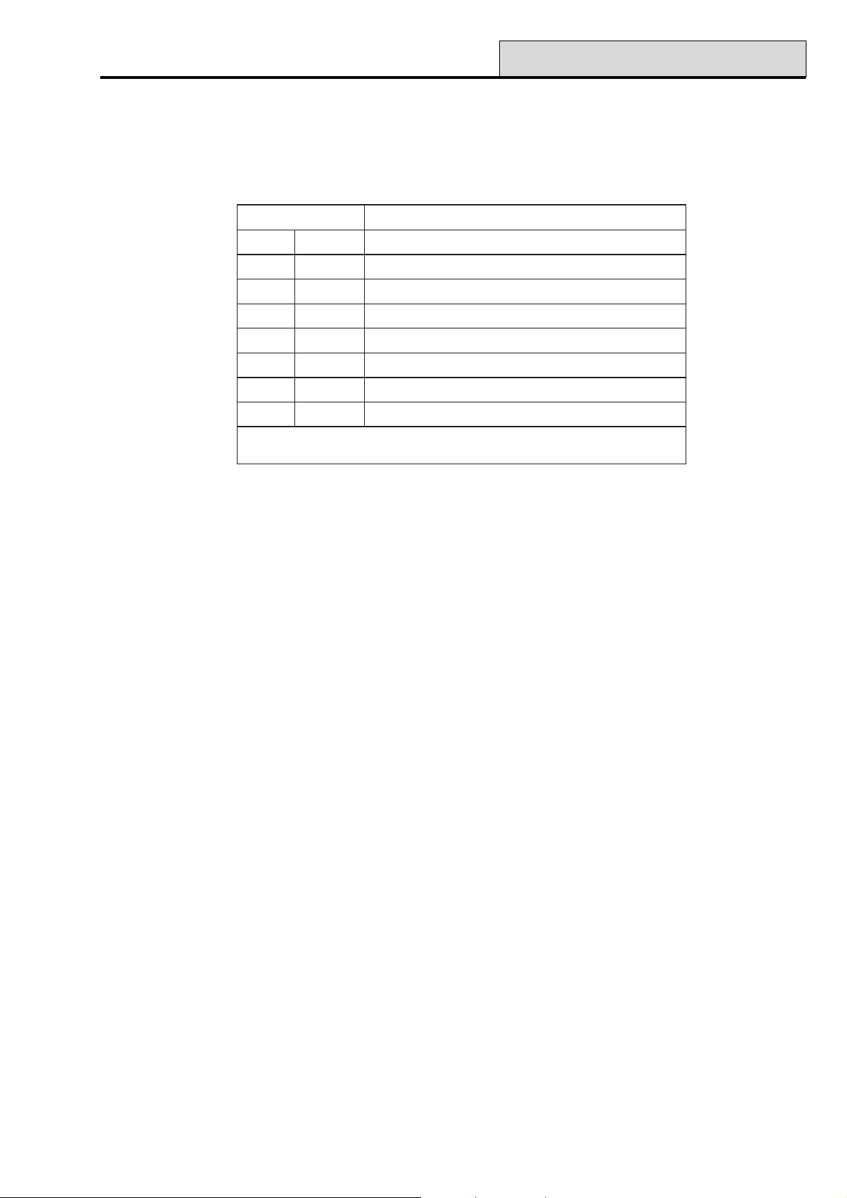
Galaxy Programming Manual
52 - Program Zones
Option 52 – Program Zones
This option is used by the engineer to modify the programming of the zones on the system. The option also
allows the attributes of the zone to be changed. The programmable options are shown in the Table that follows:
setubirttAnoitpircseD
1noitcnuFepytenozngissa
2rotpircseDnoitpircsedciremun-ahpla).xam(retcarahc61
3emihC tesnuelihwdenepoenozfitceffeemihcyliratnemom=delbane
4timOdettimoebnacenoz=delbane
5traPmetsysfognittestrapnidedulcnienoz=delbane
6emiT.pseRemitecnuobedtiucricyfidoM
7AISmotsuCtneveAIStceleS
8puorGmetsysehtnopuorgelgnisaotenozngissa
:etoN delbanesinoitpopuorGehtfiraeppaylnospuorG
.)spuorG.SNOITPO=1.36noitpootrefer(
Table 11. Zone Attributes
Selecting Zones
On entering the option, the first zone on the system is displayed; the zone address, function and group assigned are displayed on the top line, the descriptor is displayed on the bottom line. Pressing the # key toggles
the descriptor to reveal the status of the chime, omit and part attributes. If the attribute is enabled, the initial
attribute letter is displayed, if it is disabled, a dash (–) is shown. For example, chime, part and omit enabled
display as COP, if omit is disabled the display would be C – P.
From the display of the first zone, any zone on the system can be displayed by pressing the A or B keys or by
entering the address of a specific zone.
NOTE: For direct zone address selection the Galaxy 8, 18 and 60 only require the last 2 digits of the zone
address to be entered; the Galaxy 128,500, 504 and 512 require a 4 digit address to be entered.
The zone is selected for programming by pressing the ent key; the first zone programming attribute 1=Func-
tion is displayed.
Attributes
The attributes can be stepped through by pressing the A or B keys or directly selected by pressing the attribute number (1–8). Once the required attribute is on display, press the ent key to gain access for modification.
Once the attribute has been assigned press the ent key to save the programming and return to the attribute
selection level.
Pressing the esc key at any time when assigning attributes 1 and 3–8 to a zone aborts the programming and
returns to the attribute selection level. Pressing the esc key when assigning a descriptor to a zone saves the
assigned alphanumeric text and returns to the attribute selection level.
65
Page 72

52 - Program Zones (cont’d)
1 = Function
Entering the Function attribute displays the address and the current function of the selected zone along with
the zone function reference number. The zone functions can be stepped through, forwards or backwards,
using the A and B keys. Alternatively a zone function can be directly selected by entering the zone function
reference number, for example, entering the 19 displays zone function 19 = FIRE.
Once the required zone function is displayed, it is assigned to the zone by pressing the ent key.
2 = Descriptor
Each zone can be assigned with an alpha-numeric descriptor of up to 16 characters. This descriptor is assembled from the character set and/or library options. On selecting the Descriptor attribute, the currently assigned descriptor (blank by default) is displayed on the top line - an underscore shows where the next character will be positioned, and a selection of the alphabet is shown on the bottom line - the cursor flashes on the
letter L.
Press the ✴ key to erase the characters already assigned to the descriptor.
The A or B keys can be used to move the alphabet left or right until the required character is positioned
underneath the flashing cursor. When the required character is in position press the ent key to copy the character to the descriptor in the top line. Repeat this procedure to assemble the required zone descriptor.
Galaxy Programming Manual
Text Case and Library
On entering the Descriptor attribute the alpha-numeric characters are all presented in upper case. Pressing
the # key toggles the characters to lower case.
Pressing the # key when the lower case alphanumeric characters are displayed toggles to the library words.
The words can be viewed using the A or B keys or directly selected using the reference number - refer to
Appendix A - Library. When the required word is displayed, press the ent key to copy it to the descriptor.
NOTE: Library words are a maximum of 12 characters and upper case only.
3 = Chime
If the Chime attribute is set to 1 (enabled) the zone will chime momentarily whenever it is opened while the
system is unset. The Chime attribute defaults to 0 (disabled) for all zone functions.
The A or B keys can be used to toggle the status of the Chime attribute — pressing 1 or 0 will also select the
required status; press the ent key to accept the programming.
NOTE: The Chime option (full menu option 15, quick menu option 2) must be enabled if the zones are to
chime when opened.
4 = Omit
If the Omit attribute is set to 1 (enabled) the zone can be omitted from the system by using one of the omit
functions (11 = OMIT ZONES, 14 = FORCED SET, 46 = GROUP OMIT). The Omit attribute defaults
to 0 (disabled) for all zone functions.
66
Page 73

Galaxy Programming Manual
52 - Program Zones (cont’d)
The A or B keys can be used to toggle the status of the Omit attribute - pressing 1 or 0 will also select the
required status; press the ent key to accept the programming.
Galaxy 512
Only 1 zone can be omitted at any one time on the Galaxy 512. The only exception to this is the Vibration
zone function; selecting a single Vibration zone automatically omits all Vibration zones on the system -
irrespective of the group that each is assigned to.
5 = Part
If the Part attribute is set to 1 (enabled) the zone will be included in the setting procedure when one of the
part setting options is used to set the system (13 = PART SET, 17 = INSTANT PART). The Part attribute
defaults to 1 (enabled) for all zone functions except zones programmed as 09 = Keyswitch.
The A or B keys can be used to toggle the status of the Part attribute - pressing 1 or 0 will also select the
required status; press the ent key to accept the programming.
6 = Resp. Time
This function is only applicable to zones on RIO rev 1.2 and Smart PSU rev 0.7 and above.
This option allows the user to select , either Fast (10ms), System (default value programmed in 51 – Param-
eters, Option 27) or Slow (750ms), for each zone.
7 = Custom SIA
This option allows a different SIA mnemonic to be allocated to the selected zone. The default is the standard
SIA mnemonic for the zone type selection. The default mnemonic can be reselected by pressing the ✴ key.
The Table that follows shows the list of available customisable mnemonics:
oNtxettnevEnoitpircseDmralAdesolCtimOtimonUbuorTseR.rTtseTpmaT
1tluafeD
2rewoPR/TAlarotseRCA,elbuorTCATARABBUBTBJBXBAT
3yralgruBR/ABlarotseRyralgruB,mralAyralgruBABRBBBUBTBJBXBAT
4sseccAD/GDdeineDsseccA,detnarGsseccAGDDDBBUBTDJDXBAT
5eriFR/AFlarotseReriF,mralAeriFAFRFBFUFTFJFXFAT
6saGR/AGlarotseRsaG,mralAsaGAGRGBGUGTGJGXGAT
7pudloHR/AHlarotseRpudloH,mralApudloHAHRHBHUHTHJHXBAT
8taeHR/AKlarotseRtaeH,mralAtaeHAKRKBKUKTKJKXBAT
9liaFeniLR/TLlarotseReniL,elbuorTeniLTLRLBBUBTBJBXBAT
01lacideMR/AMlarotseRlacideM,mralAlacideMAMRMBMUMTMJMXBAT
11cinaPR/APlarotseRcinaP,mralAcinaPAPRPBPUPTPJPXBAT
21tsissAR/AQ
31yaleRC/ORdesolCyaleR,nepOyaleRORCRBBUBTBJBXBAT
41rlknirpSR/ASlarotseRrelknirpS,mralArelknirpSASRSBSUSTSJSXBAT
51repmaTR/ATlarotseRrepmaT,mralArepmaTATRTBTUTTBJBXTAT
61retaWR/AWlarotseRretaW,mralAretaWAWRWBWUWTWJWXBAT
71yrettaBR/TYlarotseRyrettaB,mralAyrettaBTYRYBBUBTBJBXBAT
81rezeerFR/AZlarotseRrezeerF,mralArezeerFAZRZBZUZTZJZXBAT
larotseR
ycnegremE,mralAycnegremE
AQRQBQUQTQJQXBAT
Table 12. Customisable Mnemonics
67
Page 74

52 - Program Zones (cont’d)
Galaxy Programming Manual
8 = Group (Galaxy 18, 60, 128, 500, 504 & 512)
NOTE: The Groups attribute is only available if groups have been enabled on the system (refer to option 63
= OPTIONS).
The Group attribute allows the zone to be assigned to a single group on the system. All zones default to
Group A1.
On selecting the Group attribute, the group that the zone is currently assigned to is displayed. All zones
default to group A1. Press the number of the group that the zone is to be reassigned to and press the ent key.
Galaxy 500, 504 & 512
The Galaxy 500, 504 and 512 panels have 16, 32 and 32 groups respectively; these are displayed on the
keypad in blocks of eight groups, sub-divided into A, B, C and D:
Use the A or B key to select the required group (A1–D8). When the end of a block is reached, the next
block of eight groups is displayed; use keys 1–8 to assign the relevant group in the current block to the zone;
press the ent key to accept the selection.
✴✴
Star (
✴) Group Function
✴✴
Certain zone functions have an additional Group attribute feature that allows the other groups to be affected
by their operation. This feature is assigned by pressing the ✴ key when allocating the group to the zone.
On pressing the ✴ key the display indicates the group currently assigned to the zone and prompts for other
groups to be added, for example 1✴ 1 – – – – – – –, pressing 4 and 7 assigns 1 ✴1 – – 4 – – 7 –.
Final, Secure Final, Part Final Keyswitch and Push Set Zones
If the star ✴ group feature is assigned a zone programmed as Final, Secure Final, Part Final or Push Set,
then closing the zone when setting multiple groups terminates the setting procedure for all groups assigned to
the zone.
Refer to the zone functions for further information on the operation of these zone functions.
Exit Zones
The star ✴ group feature can be assigned to a zone programmed as Exit. This allows an Exit zone to be
activated in a group which is not currently being unset without activating an Intruder alarm condition.
Refer to the zone functions for further information on the operation of this zone function.
System Alarms
The Galaxy panels have tamper and alarm monitoring circuits which are not programmable. These circuits
maintain the integrity of the system and all correspond to Group A1.
enoZmralAnoitpircseD
1000TTABUCwolyrettabtinulortnoC
2000CAUCliafCAtinulortnoC
3000REPMATDILrepmatdiltinulortnoC
4000REPMATXUAnruterrepmattinulortnoC
Table 13. Control Panel Alarms
68
Page 75

Galaxy Programming Manual
noitcnuFenoZ8yxalaG81yxalaG06yxalaG821yxalaG005yxalaG405yxalaG215yxalaG
52 - Program Zones (cont’d)
10laniF
20tixE
30redurtnI
40sruoH42
50ytiruceS
60lauD
70yrtnE
80teShsuP
90hctiwsyeK
01laniFeruceS
11laniFtraP
21yrtnEtraP
31AP
41tneliSAP
51yaleDAP
61tneliSyaleDAP
71kniL
999 9 9 9 9
999 9 9 9 9
999 9 9 9 9
999 9 9 9 9
999 9 9 9 9
999 9 9 9 9
999 9 9 9 9
999 9 9 9 9
999 9 9 9 9
999 9 9 9 9
999 9 9 9 9
999 9 9 9 9
999 9 9 9 9
999 9 9 9 9
999 9 9 9 9
999 9 9 9 9
999 9 9 9 9
81erapS
91eriF
02repmaT
12repmaTlleB
22riaPmaeB
32woLyrettaB
42liaFeniL
52liaFCA
62goL
999 9 9 9 9
999 9 9 9 9
999 9 9 9 9
999 9 9 9 9
999 9 9 9 9
999 9 9 9 9
999 9 9 9 9
999 9 9 9 9
999 9 9 9 9
Table 14A. Available Zone Functions per Galaxy Panel
69
Page 76

52 - Program Zones (cont’d)
noitcnuFenoZ8yxalaG81yxalaG06yxalaG821yxalaG005yxalaG405yxalaG215yxalaG
Galaxy Programming Manual
72sseccAetomeR
82oediV
92tixEoediV
03yaleDredurtnI
13yaleDgoL
23goLteS
33A-motsuCelbaliavaton
43B-motsuCelbaliavaton
53draugtixE
63ksaM
73tnegrU
83tesnUAP
93teseRhctiwsyeK
04desUtoN
14desUtoN
9 9999 9 9
9 9999 9 9
9 9999 9 9
9 9999 9 9
9 9999 9 9
9 9999 9 9
9999 9 9
9999 9 9
9999 9 9
9999 9 9
9999 9 9
9999 9 9
9999 9 9
24desUtoN
34desUtoN
44desUtoN
54desUtoN
64desUtoN
74noitarbiV
841-MTA
942-MTA
053-MTA
154-MTA
25dnetxEmralA
9999 9 9
9
9
9
9
9999 9 9
Table 14B. Available Zone Functions per Galaxy Panel (contd.)
70
Page 77

Galaxy Programming Manual
01 Final
Zones programmed as Final initiate the unsetting procedure and terminate setting procedure; opening the
Final zone when the system or group is set starts the entry timer; opening and then closing the Final zone
during the exit procedure sets the system or assigned groups, providing all the zones are closed. The opening
(+) and closing (–) of Final zones during the setting and unsetting procedures are recorded in the event log.
Pressing the ✴ key when programming a Final zone doubles the entry time of the group.
Opening a Final zone during the exit time is not reported on the keypad as an open zone; the Entry/Exit
Horns bleep rapidly to indicate that the zone is open.
NOTE: The termination feature of a Final zone can be extended to terminate the setting of multiple groups
by pressing the ✴ key when assigning a group to the zone. Refer to the Star ✴ Group Function.
02 Exit
Zones that protect the entry and exit routes are programmed as Exit. During the setting and unsetting procedures Exit zones have a non-alarm operation. If the Exit zone is activated while the system is set - without the
unsetting of the group being initiated - an Intruder alarm condition is activated.
52 - Program Zones (cont’d)
Opening an Exit zone during the exit time is not reported on the keypad as an open zone; the Entry/Exit
Horns bleep rapidly to indicate that the zone is open.
NOTE: The Exit zone can be assigned to multiple groups by pressing the ✴ key when assigning a group to
the zone. This allows an Exit zone to be activated in a group which is not currently being unset
without activating an Intruder alarm. Refer to the Star ✴ Group Function.
03 Intruder
The Intruder function is inactive when the system is unset. When the system is set, activation of an Intruder
zone causes a full alarm activation that requires to be reset with a code authorised for System Reset - refer
to option 51.6 = PARAMETERS.System Reset and option
51.55.3 = PARAMETERS.Confirm.Reduce Reset.
All zones (except zone 1001 and 1002 on the Galaxy 8, 18 & 60) are programmed as Intruder by default;
this includes the zones on RIOs that are added to the system at a later date.
04 24 Hours
The 24 Hours zone function is continuously operational. In the unset state, activation of the zone function
generates a local alarm condition (the Intruder outputs are not activated). If the zone is activated while the
system is set, the 24 Hours function operates the same as an Intruder function and results in a full alarm
condition. The 24 Hours zone function requires a system reset following an activation in both the set and unset
conditions.
05 Security
The operation of the Security zone function is identical to the 24 Hours zone function, except a Security
zone activation in the unset generates a local alarm (Horn outputs activated) that does not require a system
reset; any valid code (level 2 or above) cancels the alarm and resets the system. An activation in the set state
generates a full alarm that requires a system reset. The activation (+) and restoration (–) of Security zones is
recorded in the event log.
71
Page 78

52 - Program Zones (cont’d)
06 Dual (Double Knock)
The operation of the Dual (Double Knock) function is identical to the Intruder function, with the exception
that an alarm condition is activated only when there have been two activations from any Dual zones (assigned
to the same group) within a 20 minute period while the system is set.
07 Entry
This function initiates the unsetting procedure in the same way as a Final zone. However, during the setting
routine an Entry zone operates as an Exit zone type. This function is normally used in conjunction with a
Push Set zone, which acts as the exit terminator for the setting procedure.
Pressing the ✴ key when programming an Entry zone doubles the entry time of the group.
Opening an Entry zone during the exit time is not reported on the keypad as an open zone; the Entry/Exit
Horns bleep rapidly to indicate that the zone is open.
08 Push Set
This zone function is used to terminate the setting routine. The system sets when the Push Set zone, usually a
push button, is activated. The Entry/Exit Horn stops immediately the button is pressed; the system sets after
four seconds, allowing the doors to settle to the closed state. The Push Set zone remains inactive until the
next setting routine.
Galaxy Programming Manual
NOTE: The Push Set zone can be either 1kΩ going to 2kΩ or 2kΩ to 1kΩ - refer to Installation Manual
(II1-0027), System Architecture for wiring details. The first time that the Push Set is used to
terminate the setting, the button will require to be pressed twice; the first press identifies the normal
status of the button to the system.
Activating a Push Set zone during the exit time is not reported on the keypad as an open zone; the Entry/
Exit Horns bleep rapidly to indicate that the zone is open.
NOTE: The termination feature of a Final zone can be extended to terminate the setting of multiple groups
by pressing the ✴ key when assigning a group to the zone. Refer to the Star ✴ Group Function.
09 Keyswitch
The Keyswitch function allows a zone to be used as an on/off switch for the system or assigned groups.
Operating a Keyswitch zone when the system is unset starts the timed full setting routine, therefore the exit
time is applicable. The system sets when the exit time expires or a Final or Push Set is activated.
NOTE: Assigning a # to the keyswitch zone function will cause the Instant setting routine to be activated. In
this case the exit time is not applicable. If a Keyswitch Zone has its omit attribute enabled, activation
of the Keyswitch will force set the assigned groups. Only zones with the omit attribute enabled will
be omitted.
If a keyswitch zone type (9) is operated twice (i.e. set/unset) during the exit time of an autoset then the autoset
is cancelled.
Operating a keyswitch zone type during the pre-warn period of an autoset will start a Force Set. If you then
activate the switch again (i.e. unset with keyswitch) before the panel sets, the pre-warn continues on the
autoset.
NOTE: When the keyswitch is activated the second time to take panel back into pre-warn, it can be up to
10 seconds before the pre-warn tones at the keypad start up again.
72
Page 79

Galaxy Programming Manual
If the system is set, operating a Keyswitch immediately unsets the assigned groups; there is no entry time
countdown.
The Part attribute of the Keyswitch function defaults to 0 (disabled); the standard Keyswitch function full
sets the system. To part set the system using the Keyswitch, the Part attribute must be enabled.
NOTE: The operation of a Keyswitch zone can be extended to the setting and unsetting of multiple groups
by pressing the ✴ key when assigning a group to the zone. Refer to the Star ✴ Group Function.
The standard programming of the Keyswitch function requires a momentary change from 1kΩ to 2kΩ to
both set and unset the system. If the Keyswitch connected has a latching mechanism, press the ✴ key when
assigning the function; the display indicates 09=✴KEYSWITCH has been assigned. The
✴ Keyswitch operation is as follows: 1kΩ to 2kΩ sets the system; 2kΩ to 1kΩ unsets the system.
The Keyswitch function can also be programmed to reset alarms - refer to option 51.14 =
PARAMETERS.Keyswitch Level. If the Keyswitch is assigned a sufficient level to reset the alarm condition, the alarm is cancelled and immediately reset when the Keyswitch is used to unset the system following
an alarm activation.
NOTE: The activated zones are not displayed on the keypad when a Keyswitch is used to reset the alarm.
52 - Program Zones (cont’d)
10 Secure Final
This zone has dual functionality depending on whether the system is set or unset. When the system is setting,
set or unsetting the operation is identical to the Final zone function. When the system is unset the operation is
identical to the Security zone function.
Pressing the ✴ key when programming a Secure Final zone doubles the entry time of the group.
Opening a Secure Final zone during the exit time is not reported on the keypad as an open zone; the Entry/
Exit Horns bleep rapidly to indicate that the zone is open.
The termination feature of a Secure Final zone can be extended to terminate the setting of multiple groups by
pressing the ✴ key when assigning a group to the zone. Refer to the Star ✴ Group Function.
11 Part Final
This zone has dual functionality depending on whether the system is full set or part set. When the system is full
set the zone operation is identical to the Final zone function. When the system is part set the zone operation is
identical to the Intruder zone function.
Pressing the ✴ key when programming a Part Final zone doubles the entry time of the group.
Opening a Part Final zone during the exit time is not reported on the keypad as an open zone; the Entry/Exit
Horns bleep rapidly to indicate that the zone is open.
12 Part Entry
This zone has dual functionality depending on whether the system is full set or part set. When the system is full
set the zone operation is identical to the Exit zone function. When the system is part set the zone operation is
identical to the Entry zone function.
Pressing the ✴ key when programming a Part Entry zone doubles the entry time of the group.
73
Page 80

52 - Program Zones (cont’d)
13 PA
The PA (Personal Attack) function is continuously operational. Activation of this zone type overrides the Bell
Delay parameter and causes an instant full alarm condition that requires to be reset with a code authorised for
PA Reset — refer to Option 51 – PARAMETERS, 22 = PA Reset; the Intruder outputs are not acti-
vated by PA zones.
NOTES
1. If a PA zone is open, it is indicated on the keypad whenever a valid code is entered. The group that the
open PA is assigned to cannot be set until it is closed.
2. Galaxy 512 only — engineer mode cannot be exited if a PA zone is open.
14 PA Silent
The PA Silent function is identical to the PA function, with the exception that there is no audible or visual
indication of the activation; that is, no bells or strobes are activated. Only the PA output (normally channel 2
on the digital communicator) signals the alarm. The activation (+) and restoral (–) of PA Silent zones is
recorded in the event log.
NOTES
Galaxy Programming Manual
1. At the time of setting, any PA Silent zones that are currently open are reported to the user.
2. The tamper facility on the PA zone remains active while engineer mode is accessed.
3. Galaxy 128, 500, 504 & 512 — engineer mode cannot be exited if a PA Silent zone is open.
15 PA Delay
The PA Delay function is identical to the PA function, with the exception that the PA output activation can be
delayed for up to 60 seconds; this is determined by option 51.13 = PARAMETER.PA Delay. During the
period of delay the Entry/Exit Horns activate to remind the user that the PA delay is counting down; entering
a valid code or closing the PA Delay zone aborts the alarm.
NOTES
1. If a PA Delay zone is open, it is indicated on the keypad whenever a valid code is entered. The group
that the open PA Delay is assigned to cannot be set until it is closed.
2. The tamper facility on the PA zone remains active while engineer mode is accessed.
3. Galaxy 512 only — engineer mode cannot be exited if a PA Delay zone is open.
16 PA Delay Silent
The PA Delay Silent function is identical to the PA Delay function, with the exception that there is no audible
or visual indication of the activation; that is, no bells or strobes are activated. Only the PA output (normally
channel 2 on the digital communicator) signals the alarm. The activation (+) and restoral (–) of PA Delay
Silent zones are recorded in the event log.
NOTES
1. At the time of setting, any PA Delay Silent zones that are currently open are reported to the user.
2. The tamper facility on the PA zone remains active while engineer mode is accessed.
3. Galaxy 512 only — engineer mode cannot be exited if a PA Delay Silent zone is open.
74
Page 81

Galaxy Programming Manual
17 Link
This zone type has no operational function; it is designed to be used as a source of a link - refer to option 54 =
LINKS. The activation (+) and de-activation (–) of Link zones is recorded in the event log.
NOTE: option 54 = LINKS is not available on the Galaxy 8.
18 Spare
The Spare function allows any zones that are not being used to be ignored by the system; the resistance
readings from the circuit - including the tamper conditions - do not activate an alarm condition.
NOTE: It is recommended that all unused zones are programmed as Spare and that a 1kΩ 1% resistor is
connected across each of these zones.
19 Fire
The Fire function is continuously operational. When activated, a FIRE zone overrides the Bell Delay pa-
rameter and activates an instant alarm (Bell, Strobe and Fire). The keypad buzzer and control panel horn
output, if fitted, emit an interrupted tone (one second on, 0.5 seconds OFF), easily distinguishable from all
other alarm conditions. Any valid code entry cancels the Fire activation.
52 - Program Zones (cont’d)
20 Tamper
The Tamper function is continuously operational. When a Tamper zone is activated (1kΩ to 2kΩ), a tamper
alarm is generated; this requires to be reset by a code authorised for Tamper Reset - refer to option 51.7 =
PARAMETERS.Tamper Reset. If a tamper condition (open or short circuit) occurs, a tamper alarm is also
generated.
21 Bell Tamper
This function is identical to the operation of the Tamper function but is dedicated to bells, sirens and other
modules or output devices requiring tamper protection.
22 Beam Pair
This function is only operational when two consecutively addressed zones programmed as Beam Pair are
open in the set condition; the activation is identical to the Intruder function. The system cannot set if a single
Beam Pair is open.
NOTE: Beam Pair zones must be consecutively addressed; the first Beam Pair zone must have an even
number address, the second Beam Pair must have the next address (an odd number). For example,
valid Beam Pair addresses are 1036 & 1037, 2018 & 2031 - in this case, RIO 202 has not been
connected, therefore zone 2031 is the next address to 2018.
23 Battery Low
This function is used to monitor the voltage output of a standby battery connected to a power supply. The
activation (+) and de-activation (–) of Battery Low zones is recorded in the event log.
75
Page 82

52 - Program Zones (cont’d)
24 Line Fail
The Line Fail function is used to monitor the telephone line that a remote signalling device is connected to for
communications failure.
When the system is in the unset state, the first activation of a Line Fail zone causes a local alarm and the
message TELECOM FAILURE is displayed, subsequent Line Fail activations do not sound the local
alarm; the only indication is the keypad display.
When the system is set, activation of the Line Fail zone overrides the Bell Delay parameter; on unsetting the
system a local alarm is generated and the keypad gives an indication that Line Fail zone has activated. If an
alarm condition occurs while the Line Fail is active, an instant full alarm is generated.
If the Line Fail zone is active at the point of setting, a warning message is displayed; the user can choose to
continue or abort the setting procedure. It is also possible to prevent the system setting if the Line Fail is
active by enabling the Stop Set parameter (option 51.18).
25 AC Fail
This function is used to monitor a remote power supply. In the event of a power failure the AC Fail zone is
activated; the activation (+) and de-activation (–) of the zone is recorded in the event log.
Galaxy Programming Manual
26 Log
This zone type has no operational function; it is designed to record the activation of a zone in both the set and
unset state. The activation (+) and de-activation (–) of Log zones is recorded in the event log.
27 Remote Access
This function is used to disable remote servicing of the Galaxy panel. When the Remote Access zone is
active the Galaxy Gold software is prevented from gaining access to the Galaxy panel.
28 Video
This function is identical to the Intruder function, with the exception that the cumulative number of activations
from Video zones, before a full alarm is generated, is programmable. The number of activations required is
determined by the Video parameter (option 51.30); the range is 1–9 (Galaxy 8 is fixed at 2 activations). The
activation count is incremented when any Video zone in the group activates; the count is reset to zero when
the group is unset.
29 Video Exit
The Video Exit function is identical to the Video function, with the exception that the user can activate the
zone during setting and unsetting without incrementing the Video activations count. The Video output is not
activated during setting and unsetting.
76
Page 83

Galaxy Programming Manual
30 Intruder Delay
The Intruder Delay function is identical to the Intruder function, with the exception that the full alarm activa-
tion can be delayed for up to 50 minutes (0–3000 seconds); this is determined by the Delay Alarm parameter (option 51.31). The Intruder Delay zone must remain open for the period of the Delay Alarm parameter; while the zone is open the Entry/Exit Horns activate to remind the user that the Delay Alarm is counting down. Unsetting the system or closing the Intruder Delay zone aborts the alarm and resets the timer.
If a second Intruder Delay zone opens followed by the first zone closing, the Delay Alarm time continues
to count from the activation of the first zone. The Delay Alarm timer is reset only when all delay type zones
return to the closed state.
NOTE: On the Galaxy 8 the Delay Alarm parameter (option 51:31) is set to 1 minute and can not be
changed.
31 Log Delay
The Log Delay function operation is identical to the Log function, with the exception that the recording of the
zone activation can be delayed for up to 50 minutes (0–3000 seconds); this is determined by the Delay
Alarm parameter (option 51.31). Closing the Log Delay zone resets the timer and aborts the recording of
the event in the log.
52 - Program Zones (cont’d)
32 Set Log
The Set Log function is identical to the Log function, with the exception that zone activations are only re-
corded in the event log during the set period.
33 Custom A
The Custom A function allows a zone to be assembled. The functionality of the zone; when it activates; the
outputs activated; if it sets or unsets the systems; if it logs, are assigned using menu option 64 = ASSEMBLE
ZONE. Once the Custom A zone has been created, it can be assigned to as many zones as required.
34 Custom B
This function is identical in operation and assembly to Custom A.
77
Page 84

52 - Program Zones (cont’d)
35 = Exit Guard
The Exitguard function allows a zone to be used to omit other zones on the system. This is useful for permit-
ting access via doors programmed as 24 Hours or Security.
The Exitguard zone must be the source of a link (refer to option 54 = LINKS); the destination of the
Exitguard link is either a zone address or an output type.
When opened, the Exitguard omits the zone entered as the link destination; an alarm is not activated if the
Exitguard zone is open while a zone that it is omitting is open. If the destination zone is opened while the
Exitguard zone is closed, an alarm activation occurs; opening the Exitguard omits the zone and silences the
output types assigned to the link destination. Closing the Exitguard zone while the destination zone is still
open does not result in an alarm activation; closing the destination zone deactivates the link and returns the
zone to its normal operation.
NOTE: The Exitguard function cannot be used as a link source to activate a link destination output.
Programming Example: • Zone 1014 = An on/off keyswitch programmed as Exitguard.
• Zone 1015 = A door contact programmed as Security.
• Output type Link A = An output wired to a local horn and programmed as Link
A.
Galaxy Programming Manual
NOTE: Exit Guard guard zones do not omit zones open when the exit guard zone is activated , even if they
are subsequently closed.
Operation: The Security door contact (1015) can be omitted at any time by operating the Exitguard
keyswitch (1014). If the door (1015) is opened without first being omitted, then the Link A horn activates
and needs to be reset by operating the keyswitch (1014).
kniLecruoSnoitanitseD
14101=enoZ5101=enoZ
25101=enoZAkniL=tuptuO
34101=enoZAkniL=tuptuO
Table 15. Exit Guard Zones
36 Mask
The Mask function is designed to be used with detectors capable of reporting that their field of view has been
blocked or masked. The Mask function is identical to the Security function, with the exception that the
Mask output is activated instead of Security.
37 Urgent
The Urgent function is continuously operational; it is identical to the Intruder function, with the exception that
it activates a full alarm condition (including the Intruder outputs) in any set or unset condition.
78
Page 85

Galaxy Programming Manual
38 PA Unset
This PA Unset function is identical to the PA Silent function, with the exception that it is only operational
when the system is unset; the function is inactive when the group is set.
39 Keyswitch Reset
The Keyswitch Reset function allows alarms to be cancelled and the system to rearm without unsetting the
Galaxy. The level of reset authorisation is determined by the Keyswitch Level (option 51.14). The level
required to reset Intruder, PA and Tamper alarms is determined by the System Reset, Tamper Reset
and PA Reset parameters (option 51.06, 51.07 and 51.22) respectively.
This function is designed to permit a remote signal, for example REDCare’s Return Path Signalling feature, to
reset the system following an alarm condition.
47 Vibration (Galaxy 504 & 512)
The Vibration function is continuously operational and is designed for use with vault sensors. Vibration
zones can be block omitted using menu option 11 = Omit Zones. If the zone selected to be omitted from the
system is a Vibration zone, then all zones programmed with this function are omitted.
52 - Program Zones (cont’d)
NOTES
1. All Vibration zones in all groups are omitted when any Vibration zone is omitted. The user code does
not have to have access to all of the groups.
2. Vibration zones remain omitted until a single Vibration zone is manually reinstated. The unsetting of the
system does not reinstate omitted Vibration zones.
48-51 ATM-1, ATM-2, ATM-3 & ATM-4 (Galaxy 512 only)
The Galaxy 512 has four ATM (Automatic Teller Machine) zone types. These zone functions are continuously
operational and are designed for the special maintenance and restocking requirements of ATM’s.
A single ATM zone type can be omitted for the duration of the period entered in the ATM Timeout param-
eter (option 51.39). The ATM Delay parameter (option 51.38) determines the delay before the selected
ATM zones are omitted once selected by an ATM code (User 188–197). Each of the zones ATM-1 to
ATM-4 zones activates a corresponding ATM output.
NOTE: The relevant ATM outputs are activated as soon as the ATM zone is selected, not when the ATM
Delay expires.
79
Page 86

52 - Program Zones (cont’d)
On entering an ATM code, the system prompts for one of the ATM zone types to be selected; to select the
ATM zone type to be omitted use the A or B key or enter the number of the ATM zone type. Once the zone
is selected, the keypad indicates the DELAY ACCESS - the number of minutes remaining until the ATM
zones are omitted. Once the zone is omitted, the initiating keypad indicates the ACCESS TIMEOUT - the
number of minutes remaining until the selected ATM zones are reintroduced to the system. The Entry/Exit
Horns sound a warning ten and five minutes before the zones are reinstated.
The omitted ATM zone type can be reinstated at any time, or the omit period can be extended by the ATM
user code. Enter the ATM code and press the ent key; the system prompts for 1 = RESET ACCESS or 2
= ABORT ACCESS. Press 1 to restart the ATM Timeout or 2 to reinstate the omitted ATM’s.
NOTE: Only one ATM zone type may be omitted at any time.
52 Alarm Extend (G18, 60, 128, 500, 504 & 512)
The Alarm Extend function is identical to the Urgent function, with the exception that if the zone is open (and
has not been previously omitted) at the end of the bell duration (refer to option 51.1 = PARAMETERS.Bell
Time) it immediately activates another full alarm condition. Alarm Extend zones can only be omitted by
option 11 = OMIT ZONES.
Galaxy Programming Manual
80
Page 87
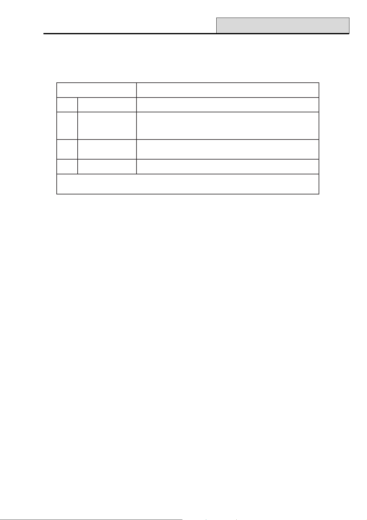
Galaxy Programming Manual
53 - Program Outputs
Option 53 – Program Outputs
This option is used by the engineer to modify the programming of the outputs on the system. The option also
allows the attributes of the outputs to be changed. The programmable options are:
setubirttAnoitpircseD
1noitcnuFtuptuOepyttuptuongissA
2edoMtuptuOteserotedocdilavseriuqer-hctaL=1
senozfosutatsnoitavitcaswollof-xelfeR=2
doirepdemmargorprofsetavitca-)sces0003-100(esluP=3
3ytiraloPtuptuOnoitavitcaniV0otgniogV21-SOP=0
noitavitcaniV21otgniogV0-GEN=1
4spuorGtuptuOtuptuoehtotspuorgngissA
delbanesinoitpopuorGehtfiraeppaylnospuorG:etoN
.)spuorG.SNOITPO=1.36noitpootrefer(
Table 16. Output Attributes
Selecting Outputs
On entering the option, the first output on the system is displayed; the output address, function and mode are
displayed on the top line, the polarity and assigned groups are displayed on the bottom line.
From the display of the first output, any output on the system can be displayed by pressing the A or B keys or
by entering the address of a specific output.
NOTE: For direct output address selection the Galaxy 8, 18 and 60 only require the last 2 digits of the
zone address to be entered; the Galaxy 128, 500, 504 and 512 require a 4 digit address to be
entered.
The output is selected for programming by pressing the ent key; the first output programming attribute 1=Op
Function is displayed.
81
Page 88
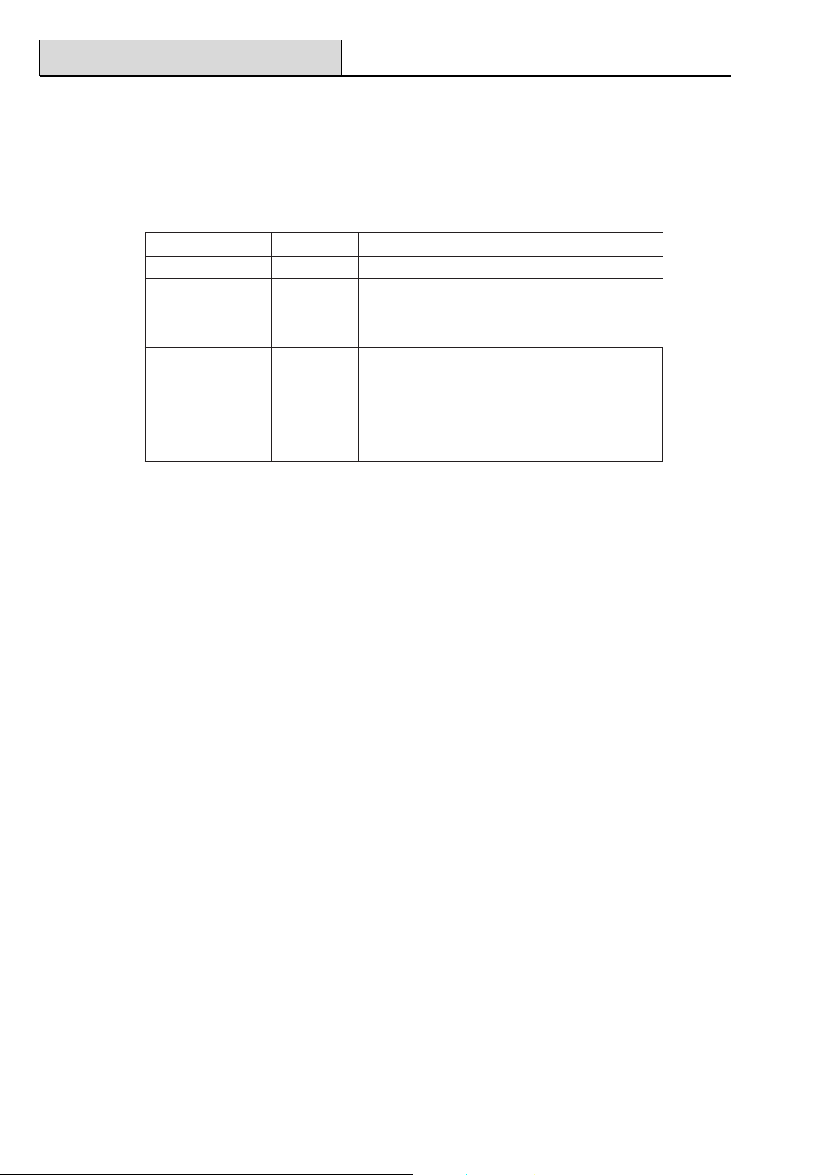
53 - Program Outputs (cont’d)
Galaxy Programming Manual
Keypad Outputs
The keypad outputs are fully programmable. The address of the keypad output is the keypad address pre-
fixed with a star, for example the output for keypad 06 is ✳06. The function of keypad outputs default to
Entry/Exit Horn.
The valid addresses of the keypads on each of the panels and the respective output addresses are indicated in
the following table:
lenaPeniLsserddAsserddAtuptuO
06&81,81F–A&9–0*–00* )1etoN(51
8213SE,C*61* )2etoN(81
1F&D,B,2–0*–01* )3etoN(21*51*71*91)2etoN(
2F&6–0*–02*&62*92
215&405,0053SE,C*61* )2etoN(81
1F&D,B,2–0*–01* )3etoN(21*51*71*91)2etoN(
2F&6–0*–02*&62*92
3F&6–0*–03*&63*93
4F&6–0*–04*&64*94
Table 17. Addresses of Valid Keypad Outputs
NOTE 1: G8, 18 and 60:- On Line 1, keypad addresses B, C, D and E are not available if the Ethernet,
ISDN, RS232 or Telecom modules respectively are fitted.
NOTE 2: G128, 500, 504 and 512:- On Line S3, keypad addresses C and E are not available if the
ISDN or Telecom modules are fitted.
NOTE 3: G128, 500, 504 and 512:- On Line 1, keypad addresses B, D and F are not available if the
Ethernet, RS232 module and engineer keypad respectively are fitted, but can be used for
keypads if these modules are not connected.
Control Horn (
✳✳
✳99)
✳✳
The control unit horn output - addressed as ✴99 - is fully programmable.
NOTE: The Galaxy 8 does not have an on-board horn output.
Attributes
The attributes can be stepped through by pressing the A or B keys or directly selected by pressing the attribute number (1–4). Once the required attribute is on display, press the ent key to gain access for modification.
Once the attribute has been assigned press the ent key to save the programming and return to the attribute
selection level. Pressing the esc key at any time when assigning attributes aborts the programming and returns
to the attribute selection level.
1 = Output Function
Entering the Output Function attribute displays the address and the current function of the selected output
along with the output function reference number. The output functions can be stepped through, forwards or
backwards, using the A and B keys. Alternatively, a function can be directly selected by entering the function
reference number, for example, entering 16 displays output function 16 = FIRE.
Once the required output function is displayed, it is assigned to the output by pressing the ent key.
82
Page 89

Galaxy Programming Manual
53 - Program Outputs (cont’d)
2 = Output Mode
Each output function defaults to a specific, logical output mode. However, the output mode of each function
can be modified to meet special requirements: when reprogrammed, the new mode applies to all outputs
assigned to that function. The output modes are:
1 = Latch: the output remains active until a valid code is entered.
2 = Reflex: the output follows the activity of the triggering event, for example, the Set output follows the
setting and unsetting of the group.
3 = Pulse: the output remains active for the programmed pulse time 1-3000 seconds (50 mins).
Programming the Output Mode
Select the required mode using the A or B keys or by selecting the number 1 – 3. Once the required mode is
on selected, press the ent key to accept the programming. If assigning the Pulse output mode, enter the pulse
time (001 – 3000 seconds) and press the ent key.
3 = Output Polarity
The Output Polarity determines the normal operational state of the output. All outputs are referred to having
positive (0 = POS) or negative (1 = NEG) polarity. An output programmed as positive polarity is 12 V in the
normal condition and goes to 0 V when activated. A negative polarity output goes from the normal condition
of 0 V to 12 V in the active state. All outputs except SET (09) default to positive output mode.
NOTE: The Switch DC output is a positive polarity output, however, the normal condition is 0 V, going to
12 V when activated. The output mode is normally Pulse.
4 = Output Groups (Galaxy 18, 60, 128, 500, 504 & 512)
NOTE: The Groups attribute is only available if groups have been enabled on the system (refer to option 63
= OPTIONS).
The Group attribute allows the output to be assigned to the groups on the system; an output can be assigned
to more than one group. All outputs default to all groups on the system.
On selecting the Output Groups attribute, the groups that the output is currently assigned to are displayed.
Press the relevant number keys to toggle the status of the group and press the ent key; if the group number is
displayed on the top line, then the group is assigned to the output; if a dash (–) appears in place of the group
number, the group has been removed from the output.
Theoutput will activate if triggered by an event in any of the groups assigned to that output, unless output
group status has been programmed.
Galaxy 500, 504 & 512
The Galaxy 500, 504 and 512 panels have 16, 32 and 32 groups respectively; these are displayed on the
keypad in block of eight groups, sub-divided into A, B, C and D:
kcolBpuorGspuorGlacisyhP
8-1A8-1
8-1B61-9
8-1C)ylno215&405(42-71
8-1D)ylno215&405(23-52
Table18. Output Groups
83
Page 90

53 - Program Outputs (cont’d)
Use the A or B key to select the required group (A1–D8). When the end of a block is reached, the next
block of eight groups is selected; press keys 1–8 to toggle the status of the relevant group in the current block
to the output; press the ent key to accept the selection.
Group Status
This group attribute offers an additional feature that makes the operation of the output conditional on the set
status of each of the system groups. An output assigned Group Status only activates if the set conditions of
the programming are met, for example, an Intruder output used to trigger a communicator can be pro-
grammed to activate only if groups 2 and 4 are set and group 3 is unset.
Groups 12345678
STATUS >-SUS----
To assign the Group Status conditions, press the ✴ key when selecting the groups: an arrow (>) is displayed
on the bottom line as well as the current Status. Press the relevant number keys to toggle the status of the
groups and press the ent key to accept the programming. The available group status conditions are:
Galaxy Programming Manual
S = Set — group must be set to allow output to activate;
U = Unset — group must be unset to allow output to activate;
– = Set or unset — output activation is independent of the group status.
84
Page 91

Galaxy Programming Manual
53 - Program Outputs (cont’d)
Output Functions
The following table shows all the outputs and the zone functions and conditions that result in their activation.
snoitcnuFtuptuOslleBebortSAPredurtnIrepmaT42
srH
noitcnuFenoZ 1020304050607080900111213141
10laniF SS–S T–X ––– –A – –
20tixE SS–S T–– ––– –A – –
30redurtnI SS–S T–– ––– –A – –
40sruoH42 SS–S TA– ––– –A – –
50ytiruceS SS–S T–– ––– –A A–
60lauD SS–S T–– ––– –A – –
70yrtnE SS–S T–– ––– –A – –
80teShsuP –––– T–X––– –– ––
90hctiwsyeK –––– T–XXS– –– ––
01laniFeruceS SS–S T–X ––– –A U–
11laniFtraP SS–S T–X ––– –A – –
21yrtnEtraP SS–S T–– ––– –A – –
31AP AAA– T–– ––– –A – –
41tneliSAP ––A– T–– ––– –A ––
51yaleDAP AAA– T–– ––– –A – –
61tneliSyaleDAP ––A– T–– ––– –A ––
71kniL ???? T?????? ?? ??
81erapS –––– T–– ––– –– ––
91eriF AA–– T–– ––– –– – –
02repmaT SS–S A–– ––– –A – –
12repmaTlleB AS–S A–– ––– –A – –
22riaPmaeB SS–S T–– ––– –A – –
32woLyrettaB –––– T––––– –– ––
42liaFeniL –––– T–– ––– –– – –
52liaFCA –––– T––––– –– – A
62goL –––– T–– ––– –A ––
72sseccAetomeR –––– T–– ––– –– ––
82oediV SS–S T–– ––– –A – –
92tixEoediV SS–S T–– ––– –A – –
03yaleDredurtnI SS–S T–– ––– –A – –
13yaleDgoL –––– T––––– –– ––
23goLteS –––– T––––– –– ––
33A-motsuC ???? T?????? ?? ??
43B-motsuC ???? T?????? ?? ??
53draugtixE LLLL TLLLLLL LL LL
63ksaM SS–S T–– ––– –A – –
73tnegrU AA–A T–– ––– –A – –
83tesnUAP ––U– T–– ––– –U ––
93teseRhctiwsyeK –––– T–X––– –– ––
64–04desUtoN –––– ––– ––– –– ––
74noitarbiV AA–A T–– ––– –A – –
841-MTA AA–A T–– ––– –A – –
942-MTA AA–A T–– ––– –A – –
053-MTA AA–A T–– ––– –A – –
154-MTA AA–A T–– ––– –A –
25dnetxEmralA AA–A T–– ––– –A – –
teseRhctiwS
teSreenignEerapSydaeRytiruceSCA
CD
Key:
S = Activates when system is set ? = Activation dependant on system programming
P = Activates when system is Part Set X = Activates during Exit Time
U = Unset E = Activates during Entry Time
A = Activated in any condition L = Switches output off if linked to destination output
- = No effect T = Activates if zone resistance is <800Ω or >12000Ω
O= Activates when zone is omitted
liaF
Table 19A. Output Activations per Zone
85
Page 92

53 - Program Outputs (cont’d)
Galaxy Programming Manual
snoitcnuFtuptuOttaB
noitcnuFenoZ 516171819102122232425262728292
10laniF ––S EXS – - – S – –––– S –
20tixE ––S EXS – S – S – –––– S –
30redurtnI ––S EXS – S – S – –––– S –
40sruoH42 ––SA – – –S–––––S –
50ytiruceS ––S A – – –S–––––S –
60lauD ––S EXS – S – S – –––– S –
70yrtnE ––S EXS – - – S – –––– S –
80teShsuP ––– X – – –––––––– –
90hctiwsyeK ––– – X – –– –––––– –
01laniFeruceS ––AA X S –S–––––S –
11laniFtraP ––A EXS X S – S – –––– S –
21yrtnEtraP ––A EX – S – S – –––– S –
31AP ––A– – – –– –––––A –
41tneliSAP ––– – – – –––––––– –
51yaleDAP ––AA – – –– –––––A –
61tneliSyaleDAP ––– – – – –– –––––– –
71kniL ??? ? ? ? ?? ?????? ?
81erapS ––– – – – –– –––––– –
91eriF –AA A – – –V––––AA –
02repmaT ––AA – – –S–––––S –
12repmaTlleB ––A A – – –S–––––S –
22riaPmaeB ––S EXS – – – S – –––– S –
32woLyrettaB U– – – – – –– – –––– – –
42liaFeniL ––– U – – A––––––– –
52liaFCA ––– – – – –– –––––– –
62goL ––– – – – –––––––– –
72sseccAetomeR ––– – – – –––––––– –
82oediV ––S EXS – S – S – –––– S –
92tixEoediV ––S EXS – S – S – –––– S –
03yaleDredurtnI ––S EXS – – – S – –––– S –
13yaleDgoL ––– – – – –––––––– –
23goLteS ––– – – – –––––––– –
33A-motsuC ??? ? ? ? ???????? ?
43B-motsuC ??? ? ? ? ???????? ?
53draugtixE LLL L L L LLLLLLLL L
63ksaM ––S EXS – – – S – –––– S –
73tnegrU ––AA – – –– –––––A –
83tesnUAP ––– – – – –– –––––– –
93teseRhctiwsyeK ––– – – – –––––––– –
64–04desUtoN ––– – – – –– –––––– –
74noitarbiV ––– – – – –– –––––– –
841-MTA ––– – – – –––––––– –
942-MTA ––– – – – –––––––– –
053-MTA ––– – – – –––––––– –
154-MTA ––– – – – –––––––– –
25dnetxEmralA AA– A T – –– – –––A– –
eriFnroHnroHE/EtraP
woL
teS
mrifnoCeniL
oediVmmoC
liaF
ttaB
gnorW
liaF
tseT
trelADYLD
DC
oN
eriF
mra-eR
A-remiT
Key:
S = Activates when system is set ? = Activation dependant on system programming
P = Activates when system is Part Set X = Activates during Exit Time
U = Unset E = Activates during Entry Time
A = Activated in any condition L = Switches output off if linked to destination output
- = No effect T = Activates if zone resistance is <800Ω or >12000Ω
O= Activates when zone is omitted
Table 19B. Output Activations per Zone (Cont’d)
86
Page 93

Galaxy Programming Manual
53 - Program Outputs (cont’d)
snoitcnuFtuptuOB-remiTklaW
noitcnuFenoZ 03132333435363738393041424344454
10laniF –UOA – ––?S––––––––
20tixE –UOA – ––?S––––––––
30redurtnI –UOA – ––?S––––––––
40sruoH42 –UOA – ––?S––––––––
50ytiruceS –UOA – – –?S––––––––
60lauD –UOA – – –?S––––––––
70yrtnE –UOA – ––?S––––––––
80teShsuP –UOA – –––––––––––
90hctiwsyeK –UOA – –––––XU––––U
01laniFeruceS –UOA – –––––––––––
11laniFtraP –UOA – –––––––––––
21yrtnEtraP –UOA – –––––––––––
31AP –UOA – –––––––––––
41tneliSAP –UOA – –––––––––––
51yaleDAP –UOA – –––––––––––
61tneliSyaleDAP –UOA – –––––––––––
71kniL ??U?O? ? ????????–??
81erapS –––A – ––––––– – ? – –
91eriF –UOA – ––?A––––––––
02repmaT –UOA – ––?A––––––––
12repmaTlleB –UOA – ––?A––––––––
22riaPmaeB –UOA – –––––––––––
32woLyrettaB –UOA – –––––––––––
42liaFeniL –UOA – –––––––––––
52liaFCA –UOA – –––––––––––
62goL –UOA – –––––––––––
72sseccAetomeR –UOA – –––––––––––
82oediV –UOA – ––?S––––––––
92tixEoediV –UOA – – –?S––––––––
03yaleDredurtnI –UOA – ––?S––––––––
13yaleDgoL –UOA – –––––––––––
23goLteS –UOA – –––––––––––
33A-motsuC ???O? ? ????????–??
43B-motsuC ???O? ? ???????????
53draugtixE LLOLL L LLLLLLLL?LL
63ksaM –––– – ––– EPS––– – L ? –
73tnegrU –UOA – – –?A––––––––
83tesnUAP –UOA – ––?U––––––––
93teseRhctiwsyeK –UOA – –––––––––––
64–04desUtoN –––– – –––––––––––
74noitarbiV –UOA – ––?A––––––––
841-MTA –UOA – – –?A––––––––
942-MTA –UOA – ––?A––––––––
053-MTA –UOA – ––?A––––––––
154-MTA –UOA – – –?A––––––––
25dnetxEmralA –UOA – – –?A––––––––
enoZ
tseT
gninraWmotsuC
timO
A
motsuC
B
tseTteseR
ksaMdilaV
DQR
liaF
dc
sseruDlagellI
teS
xaM
edoC
trobAtesnU
pmaT
Key:
S = Activates when system is set ? = Activation dependant on system programming
P = Activates when system is Part Set X = Activates during Exit Time
U = Unset E = Activates during Entry Time
A = Activated in any condition L = Switches output off if linked to destination output
- = No effect T = Activates if zone resistance is <800Ω or >12000Ω
O= Activates when zone is omitted
Table 19C. Output Activations per Zone (Cont’d)
87
Page 94

53 - Program Outputs (cont’d)
Galaxy Programming Manual
snoitcnuFtuptuOetaLteSS/U
ylraE
noitcnuFenoZ 647484940556-15667696-86071757-27
10laniF – – ? – – ? ––– – – –
20tixE – – ? – – ? ––– – – –
30redurtnI – – ? – – ? ––– – – –
40sruoH42 – – ? – – ? ––– – – –
50ytiruceS – – ? – – ? ––– – – –
60lauD – – ? – – ? ––– – – –
70yrtnE – – ? – – ? ––– – – –
80teShsuP ?U?S – – – ? ––– – – –
90hctiwsyeK – – ? – – ? ––– – – –
01laniFeruceS – – ? – – ? ––– – – –
11laniFtraP – – ? – – ? ––– – – –
21yrtnEtraP – – ? – – ? ––– – – –
31AP – – ? – – ? ––– – – –
41tneliSAP – – ? – – ? ––– – – –
51yaleDAP – – ? – – ? ––– – – –
61tneliSyaleDAP – – ? – – ? ––– – – –
71kniL ? ? ? ? ? ? ??? ? ? ?
81erapS – – ? – – ? ––– – – –
91eriF – – ? – – ? ––– – – –
02repmaT – – ? – – ? ––– – – –
12repmaTlleB – – ? – – ? ––– – – –
22riaPmaeB – – ? – – ? ––– – – –
32woLyrettaB – – ? – – ? ––– – – –
42liaFeniL – – ? – – ? ––– – – –
52liaFCA – – ? – – ? ––– – – –
62goL – – ? – – ? ––– – – –
72sseccAetomeR – – ? – – ? ––– – – –
82oediV – – ? – – ? ––– – – –
92tixEoediV – – ? – – ? ––– – – –
03yaleDredurtnI – – ? – – ? ––– – – –
13yaleDgoL – – ? – – ? ––– – – –
23goLteS – – ? – – ? ––– – – –
33A-motsuC ? ? ? ? ? ? ??? ? ? ?
43B-motsuC ? ? ? ? ? ? ??? ? ? ?
53draugtixE L L L L L L LLL L L L
63ksaM – – ? – – ? ––– – – –
73tnegrU – – ? – – ? ––– – – –
83tesnUAP – – ? – – ? ––– – – –
93teseRhctiwsyeK – – ? – – ? ––– – – –
64–04desUtoN – – ? – – ? ––– – – –
74noitarbiV – – ? – – ? ––– – A –
841-MTA – – ? – – ? ––– – – O
942-MTA – – ? – – ? ––– – – O
053-MTA – – ? – – ? ––– – – O
154-MTA – – ? – – ? ––– – – O
25tnetxEmralA – – ? – – ? ––– – – –
nraW-erPtesotuAdesUtoNO-AkniLFR
FR
maJ
toN
repuS
desU
tuokcoLbiV
tseT
4-1mtA
Key:
S = Activates when system is set ? = Activation dependant on system programming
P = Activates when system is Part Set X = Activates during Exit Time
U = Unset E = Activates during Entry Time
A = Activated in any condition L = Switches output off if linked to destination output
- = No effect T = Activates if zone resistance is <800Ω or >12000Ω
O= Activates when zone is omitted
Table 19D. Output Activations per Zone (Cont’d)
88
Page 95

Galaxy Programming Manual
01 Bells (Latch)
The Bells output is activated on a full alarm event when the system is set. This output is subject to the Bell
Time, Bell Delay and No. Rearm parameters.
02 Strobe (Latch)
The Strobe output is activated on a full alarm event during the set state. This output is subject to the Bell
Delay. The Strobe output follows the Bell Time, but latches on after the last rearm.
03 PA (Latch)
The PA output is activated whenever any of the PA zone types activate. The output is not subject to the
Rearm parameter; it latches on remains active until a valid code, with the appropriate PA Reset level, is
entered.
04 Intruder (Latch)
The Intruder output is activated on a full alarm event during the set state. Dependent upon the programming
of parameter 51.56 Force Restore the intruder output restore is either subject to the Confirm Time Window
+ unset or entry of a valid code with the appropriate system reset level.. Refer to the 51.56 Force Restore
description for further details.
53 - Program Outputs (cont’d)
05 Tamper (Latch)
The Tamper output is activated whenever a circuit tamper or lid tamper occurs. The output is not subject to
the Rearm parameter: it latches on and remains active until a valid code, with the appropriate Tamper Reset
level, is entered.
The output is also activated on the first entry of the engineer code when accessing engineer mode.
NOTE: The Tamper output is not activated on the Galaxy 512 when engineer access is authorised by the
user.
06 24 Hours
The 24 Hours output is activated whenever a 24 Hour zone is activated. The output is not subject to the
Rearm parameter: it latches on and remains active until a valid code, with the appropriate System Reset
level, is entered.
07 Reset (Latch)
The Reset output type is used as a control line output to latch, freeze and reset movement detector LEDs.
08 Switch DC (Pulse)
This Switch DC output is used to power detectors that require a momentary power interruption to reset them,
for example, break glass or vibration detectors. This output reverses its polarity (changes from 0V to 12V) for
the period of the Pulse output mode when the setting procedure has been initiated.
NOTE: When installing detectors that require to be powered from a Switch DC output, connect the positive
lead of the detector to the 12V terminal of a power supply and the negative lead to Switch DC
output terminal. Do not change the Output Polarity to 1=Neg: it must remain as positive polarity.
89
Page 96

53 - Program Outputs (cont’d)
09 Set (Reflex)
The Set output is activated when the assigned groups on the system are set. This output is a Reflex output
and follows the set and unset status of the groups.
10 Engineer (Reflex)
The Engineer output is activated while the engineer mode is being accessed.
11 Spare (Latch)
The Spare output has function: it is used to designate outputs that are not being used on the system.
12 Ready (Reflex)
The Ready output is active when all zones in the system (group) are closed. This output activates in both the
unset and set conditions.
13 Security (Latch)
The Security output is activated whenever a Security zone is activated. The output is not subject the Rearm
parameter: it latches on and remains active until a valid code (level 2 or above) is entered.
Galaxy Programming Manual
14 AC Fail (Reflex)
The AC Fail output indicates the status of the a.c. (mains) power supply. The output activates when the a.c.
supply fails or an AC Fail zone is activated. The output is reset when the a.c. supply is restored or the AC
Fail zone is closed. The activation is delayed subject to the time entered in the 20=Power Delay parameter.
15 Battery Low (Reflex)
The Battery Low output activates whenever the control unit stand-by battery falls below 10.5V or a Battery
Low zone is activated. The output is restored when the voltage rises above 10.5V or the Battery Low zone
is closed.
16 Fire (Latch)
The Fire output is activated whenever a Fire zone is activated. The output is not subject to the Rearm
parameter: it latches on and remains active until a valid code (level 2 or above) is entered.
17 Horn (Latch)
The Horn output is a general alarm output and is activated by most zone types in both the local and full alarm
modes. For example, a Fire zone activation causes the Horn output to pulse on and off – on for 0.5 seconds,
off for 0.1 seconds. The Horn output is subject to the Bell Time, Bell Delay and No. Rearm parameters.
90
Page 97

Galaxy Programming Manual
18 E/E Horn (Latch)
The Entry/Exit Horn output has a dual function:
• in an alarm condition its function is identical to that of the Horn output;
• during the unsetting and setting of the system it is used to provide an indication on the
status of the system. The indication states are as follows:
• General Alarm - ON 500 msecs. OFF 500 msecs.
• Clear to Exit - Continuous
• Exit interrupted - ON 100 msecs. OFF 100 msecs.
• 75% Exit Time - ON 200 msecs. OFF 200 msecs.
• Set - ON 600 msecs. OFF 600 msecs (twice)
• Normal Entry - ON 800 msecs. OFF 200 msecs.
• 75% Entry Time - ON 200 msecs. OFF 200 msecs.
• Fire - ON 500 msecs. OFF 100 msecs.
• Chime - ON 500 msecs. OFF 400 msecs (twice)
19 Part Set (Reflex)
The Part Set output is activated when the assigned groups on the system are part set. This output is a Reflex
output and follows the part set and unset status of the groups.
53 - Program Outputs (cont’d)
20 Confirm (Latch)
The Confirm output is activated when there have been activations on two separate zones: the second activa-
tion must occur within the Confirm Time Window. The zones do not have to be in the same group, however,
both groups must be assigned to the Confirm output to allow activation. Cross-group confirmation is controlled by the Communications programming in menu 56.1, Telecoms. If signalling is by DTMF format, cross-
group confirmation can occur on groups that share the same confirm channel. In all other signalling formats,
cross-group confirmation can occur on groups that share the same account number.
NOTE: The Confirm output is used to give positive identification that a genuine intruder alarm condition has
occurred and to minimise the possibility of false alarm activations.
21 Line Fail (Reflex)
The Line Fail output is activated whenever a Line Fail zone is active or the telecom module detects and
sustains a line failure for more than 30 seconds.
22 Video (Pulse)
The Video output is activated by the Video zone when the system is set. This output can be used to activate
video recorder or video transmission systems.
23 Comm Fail (Latch)
The Comm Fail output is activated whenever there is a communication failure on the telecoms module tel-
ephone line. A fail to communicate event overrides the remaining Bell Delay period.
91
Page 98

53 - Program Outputs (cont’d)
24 Batt Test
This test output is used on V4 and above.
25 Wrong CD
This output is activated whenever a wrong code alarm occurs. That is, when 6 wrong codes in succession are
entered at the keypad. The output, by default pulses on for 90 seconds.
26 Alert (Latch) (Galaxy 60, 128, 500, 504 & 512)
The Alert output is activated when the control panel loses communication with one of the remote modules or
keypads.
27 Fire Delay (Latch) (Galaxy 60, 128, 500, 504 & 512)
The Fire Delay output is activated whenever a Fire zone is activated. The activation of the output is delayed
subject to the period determined by the 03=Abort Time parameter. The Fire Delay output is not subject to
the Rearm parameter: it latches on and remains active until a valid code (level 2 or above) is entered.
28 No Re-Arm (Latch)
Galaxy Programming Manual
The No Rearm output is activated on a full alarm event during the set state: it is subject to the Bell Delay
parameter. The No Rearm output is similar to the strobe output, but it stays on at the end of the bell time,
until unset.
29 Timer A (Reflex) (Galaxy 60, 128, 500, 504 & 512)
The Timer-A output is controlled by the Timer-A option (refer to option 65=Timers A/B) and activates in
accordance with the programmed on and off times assigned to the function.
30 Timer B (Reflex) (Galaxy 60, 128, 500, 504 & 512)
The Timer-B output is controlled by the Timer-B option (refer to option 65=Timers A/B) and activates in
accordance with the programmed on and off times assigned to the function.
NOTE: If the TIMER A or B outputs are programmed as LATCH mode, then they can only be reset by a
user code with access to all of the groups assigned to the relevant timer.
31 Walk Test (Reflex) (Galaxy 60, 128, 500, 504 & 512)
The Walk Test output is activated when a zone included in the walk test is tested (refer to option 31=Walk
Test).
32 Zone Omit (Reflex)
The Zone Omit ouput is activated as soon as a zone is omitted from the system by option 11=OMIT
ZONES or by option 54=LINKS. If the Output Mode attribute is assigned as:
• Reflex (default) the output remains active until the zone is reinstated;
• Latch the output is reset on entry of a valid code.
92
Page 99

Galaxy Programming Manual
33 Warning (Latch) (Galaxy 60, 128, 500, 504 & 512)
The Warning output is activated by the first occurrence of a high (1200-1300Ω) and low (800-900Ω)
resistance reading on each of the system zones in a single 24 hour period: the activating zone is recorded in the
log.
NOTE: The time period finishes at midnight, not 24 hours from first activation.
Subsequent high and low resistance readings from the same zone on the same day do not activate the output if
it has been reset by a valid user code.
NOTE: If a low resistance reading is followed by a high resistance reading, the Warning output activates on
the first occurrence of both activations.
34 Custom A (Latch) (Galaxy 60, 128, 500, 504 & 512)
The Custom-A output is activated whenever a Custom-A zone is activated.
35 Custom B (Latch) (Galaxy 60, 128, 500, 504 & 512)
The Custom –B output is activated whenever a Custom-B zone is activated.
53 - Program Outputs (cont’d)
36 Test (Pulse) (Galaxy 60, 128, 500, 504 & 512)
The Test output is activated at 12:00 hours each day for two seconds – the period of the Pulse can be
altered. This output can be used to perform a daily test on a digicom connected to the system.
37 Rest RQD (Latch) (Galaxy 60, 128, 500, 504 & 512)
The Reset RQD output is activated when a system, tamper or PA alarm has occurred that requires to be
reset by the engineer (level 7) code. Refer to option 51=PARAMETERS for details modifying the code
levels assigned to the 06=System Reset, 07=Tamper Reset and 22=PA Reset parameters.
38 Mask (Latch) (Galaxy 60, 128, 500, 504 & 512)
The Mask output is activated whenever a Mask zone is activated. The output is not subject to the Rearm
parameter: it latches on and remains active until a valid group code (level 2 or above) is entered.
39 Valid Code (Reflex) (Galaxy 60, 128, 500, 504 & 512)
The Valid Code output is activated by the entry of any valid code. If the Output Mode assigned is Reflex,
the output remains active while the user is accessing the menu and setting and unsetting the system. Once the
menu is exited or the system sets or unsets, the output is restored.
40 Fail Set (Latch) (Galaxy 60, 128, 500, 504 & 512)
The Fail Set is activated if the system (or assigned groups) fails to set within the time assigned in parameter
35=Fail to Set – refer to option 51=PARAMETERS.
41 Duress (Latch)
The Duress function is activated on entry of a Duress Code (any valid code followed by two #’s, or a code
assigned as a Duress Code using menu option 42 – Codes). The output is not subject to the Rearm parameter: it latches on and remains active until a valid code (level 2 or above) is entered.
93
Page 100

53 - Program Outputs (cont’d)
42 Illegal Code (Latch) (Galaxy 60, 128, 500, 504 & 512)
The Illegal Code is activated 60 seconds after an entry of a single Dual Code or a code which is entered
outwith the Timer A and/or Timer B times assigned to it in menu option 42.1.4=CODES.User
Codes.Time Zone.
43 Max Tamp (Latch)
The MAX TAMP output is activated when a MAX, MicroMAX or MAX
44 Abort (Latch)
The ABORT output is activated when a valid code is entered during the Abort period on system entry.
45 Unset
The Unset output is activated each time the system (or group) is unset. The default output mode attribute is
programmed as pulse, for two seconds. This can be used to activate a buzzer to notify a user that the system
has been unset, when using an RF fob.
46 Set Late (Latch) (Galaxy 128, 500, 504 & 512)
Galaxy Programming Manual
3
tamper is activated.
The Set Late output is activated if the system has not been set by the programmed Monitor time – refer to
option 65.3.1=TIMERS.Autoset.Status.
47 U/S Early (Latch) (Galaxy 128, 500, 504 & 512)
The Unset Early output is activated if the system has been unset before the programmed Monitor time –
refer to option 65.3.1=TIMERS.Autoset.Status.
48 Prewarn (Reflex) (Galaxy 128, 500, 504 & 512)
The Prewarn output is active during the programmed prewarning period of the autoset function. The mode is
Reflex. The Prewarn emits a constant tone if the autosetting of the system can be extended. If an extension
is not possible, the Prewarn output pulses.
49 Autoset (Reflex) (Galaxy 128, 500, 504 & 512)
The Autoset output is activated when the system has been set by the autoset function – refer to option
65.3=TIMERS.Autoset. The default Output Mode attribute is programmed as Reflex, therefore the output
remains active until the system unsets.
NOTE: The Set is also activated when the system autosets.
50 Not Used
94
 Loading...