

Page 1
FY 32
Einbau-Anleitung . Installation Instructions
Instructions de montage
1.
1
3
2.
5
2
5.
①
5
EB-FY32 Rev. C
4
Page 2
D
1. Einbau
Beim Einbau sind die örtlichen Vorschriften,
sowie allgemeine Richtlinien und die Einbau-Anleitung zu beachten. Der Einbauort
muß frostsicher und gut zugänglich sein.
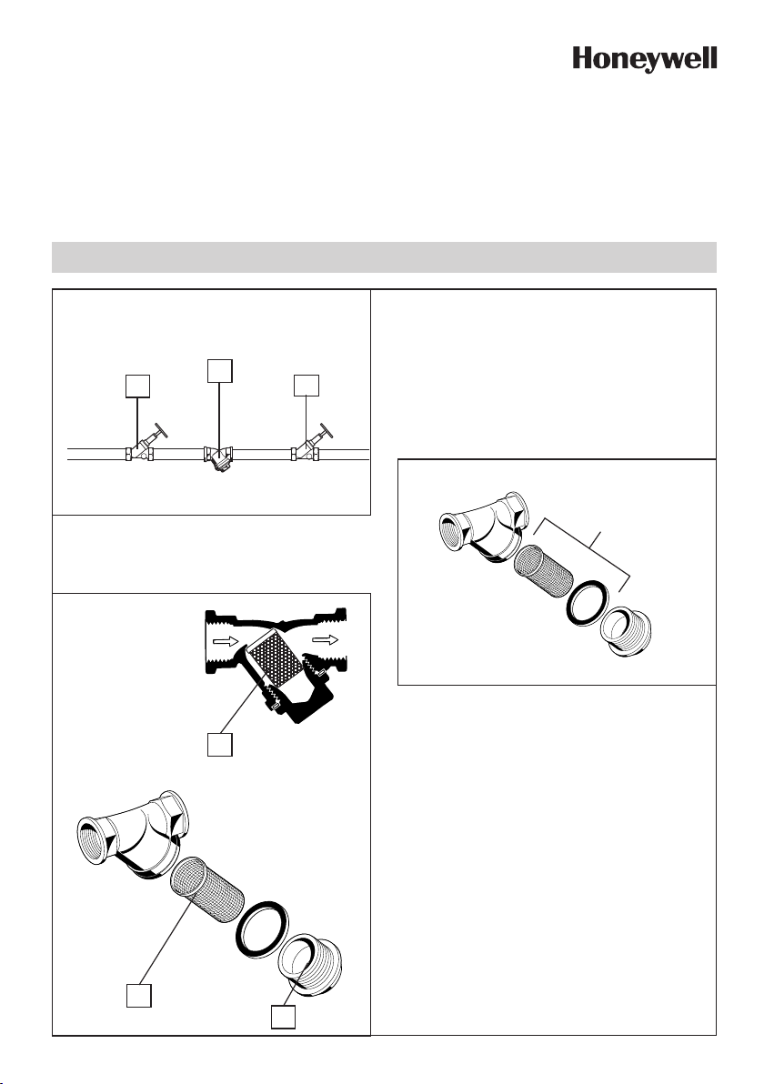
1.1 Montage (Abb. 1)
1. Rohrleitung gut durchspülen.
2. Ventil 1 und 2 schließen.
3. Schmutzfänger 3 einbauen
● Einbaulage möglichst in waagrechte
Rohrleitung
● Verschlußstopfen nach unten.
4. Ventil 1 und 2 langsam öffnen.
2. Instandhaltung (Abb.2)
Abhängig von den Betriebsbedingungen
muß das Sieb 5 gereinigt bzw. gewechselt
werden.
1. Absperrventil 1 und 2 schließen.
2. Verschlußstopfen 4 öffnen.
3. Sieb 5 herausnehmen und reinigen
● Eine Nichtbeachtung kann zu Sieb-
verstopfung führen. Druckabfall und
sinkender Wasserdurchfluß sind die
Folge.
● Das Sieb ist aus nichtrostendem
Stahl. Roter Belag infolge von Rost
aus den Rohrleitungen hat keinen
Einfluß auf Funktion und Filterwirkung.
5. Montage in umgekehrter Reihenfolge.
6. Absperrventil 1 und 2 wieder öffnen.
3. Verwendungsbereich
Anschlußgrößen R 1/4" - 2"
Medium Wasser, Öl, Preßluft,
Dampf und andere nicht
aggresive Medien
Betriebsdruck max. 16 bar (bei Wasser,
Öl, Preßluft)
max. 4 bar (bei Dampf)
Betriebstemperatur max. 150 °C
Einbaulage in waagrechte oder
senkrechte Rohrleitung
mit Verschlußstopfen
nach unten
4. Sicherheitshinweise
1. Benutzen Sie das Gerät
● in einwandfreiem Zustand
● bestimmungsgemäß
● sicherheits- und gefahrenbewußt.
2. Beachten Sie die Einbau-Anleitung.
3. Lassen Sie Störungen, welche die
Sicherheit beeinträchtigen können,
umgehend beseitigen.
4. Der Schmutzfänger FY 32 ist ausschließlich für die in dieser EinbauAnleitung genannten Einsatzgebiete
bestimmt. Eine andere oder darüber
hinausgehende Benutzung gilt als
nicht bestimmungsgemäß.
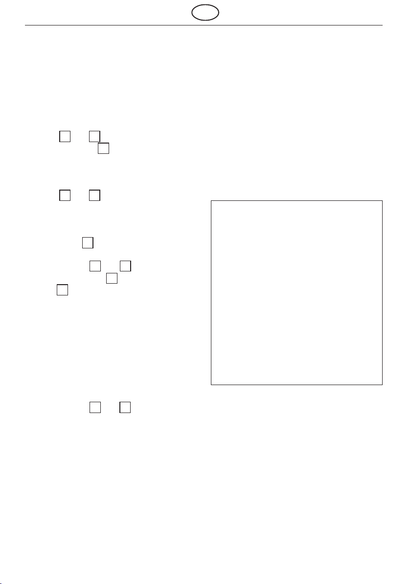
5. Ersatzteile (Abb. 5)
① Ersatzsieb mit Dichtring
Maschenweite 0,25 mm
1
/4" ES 32 - 3/8 C
3
/8" ES 32 - 3/8 C
1
/2" ES 32 - 1/2 C
3
/4" ES 32 - 3/4 C
1" ES 32 - 1 C
11/4" ES 32 - 11/4 C
11/2" ES 32 - 11/2 C
2" ES 32 - 2 C
2
Page 3

GB
1. Installation
It is necessary during installation to
observe codes of good practice, to comply
with local requirements and to follow the
installation instructions. The installation
location should be protected against frost
and be easily accessible.
1.1 Assembly (Fig. 1)
1. Thoroughly flush pipework.
2. Close valves 1 and 2 .
3. Install the Y strainer 3
● Where possible, fit in horizontal
pipework.
● Seal plug pointing downwards
4. Slowly open valves 1 and 2 .
2. Maintenance (Fig. 2)
The strainer 5 should be cleaned or
replaced as appropriate for system
conditions.
1. Close valves 1 and 2 .
2. Open seal plug 4 .
3. Remove strainer 5
● If this is not done, strainer blockage
can occur, resulting in pressure loss
and reducing water flow rate
● The strainers are of stainless steel.
Red deposits from the pipework do
not affect the function or filtering
efficiency.
5. Reassemble in the reverse sequence.
6. Open valves 1 and 2 .
3. Range of application
Connection sizes: R 1/4" to 2"
Medium: Water, oil,
compressed air,
steam and other nonaggressive mediums.
Operating pressure: Maximum 16.0 bar
(for water, oil or
compressed air)
Maximum 4.0 bar (for
steam)
Operating Maximum 150 °C.
temperature
Installation position: In horizontal or
vertical pipework with
seal plug pointing
downwards.
4. Safety guidelines
1. Use the appliance
● In good condition
● According to regulations
● With due regard to safety.
2. Follow installation instructions
3. Immediately rectify any malfunctions
which may influence safety.
4. FY 32 Y strainers are exclusively for
use in applications detailed in these
installation instructions. Any variation
from this or other use will not comply
with requirements.
5. Replacement parts (Fig. 5)
① Replacement strainer with Seal ring,
0.25mm mesh size
1
/4" ES 32 - 3/8 C
3
/8" ES 32 - 3/8 C
1
/2" ES 32 - 1/2 C
3
/4" ES 32 - 3/4 C
1" ES 32 - 1 C
11/4" ES 32 - 11/4 C
11/2" ES 32 - 11/2 C
2" ES 32 - 2 C
3
Page 4

F
1. Installation
Lors de l'installation il faudra respecter les
prescriptions locales ainsi que les
directives générales et les instructions de
montage. Le lieu d'installation sera à l'abri
du gel et bien accessible.
1.1 Montage (Fig. 1)
1. Bien rincer la tuyauterie.
2. Fermer les vannes 1 et 2 .
3. Monter le capteur d'impuretés 3
● Montage si possible dans un tuyau
horizontal
● Bouchon de fermeture dirigé vers le
bas.
4. Ouvrir lentement les vannes 1 et 2 .
2. Maintenance (Fig. 2)
Selon les conditions de travail il y a lieu de
nettoyer ou bien de remplacer le tamis 5 .
1. Fermer les vannes d'arrêt 1 et 2 .
2. Ouvrir le bouchon de fermeture 4 .
3. Retirer le tamis 5
● Si cela ne se fait pas, le tamis pourra
se boucher et provoquer une chute de
pression et réduire le débit d'eau
● Les tamis sont en acier inoxydable.
Un dépôt rougeâtre occasionné par la
rouille provenant de la tuyauterie
n'influera pas sur la fonction ni sur
le fonctionnement du filtre.
5. Remontage en sens inverse.
6. Ouvrir les vannes d'arrêt 1 et 2 .
Automation and Control Solutions
Honeywell GmbH
Hardhofweg
74821 Mosbach
Phone: (49) 6261 810
Fax: (49) 6261 81309
www.honeywell.com
Manufactured for and on behalf of the Environmental
and Combustion Controls Division of Honeywell
Technologies Sàrl, Ecublens, Route du Bois 37,
Switzerland by its Authorised Representative
Honeywell GmbH
MU1H-1123GE23 R0207
Subject to change without notice
© 2007 Honeywell GmbH
3. Domaine d'application
Diamètres de
raccordement R
Milieu Eau, huile, air comprimé,
Pression de max. 16 bar (en cas d'eau,
service huile, air comprimé)
Température
de travail max. 150 °C
Position de dans un tuyau horizontal ou
montage vertical le bouchon de
1
/4" - 2"
vapeur et autres milieux
non-agressifs
max. 4 bar (en cas de vapeur)
fermeture étant dirigé vers
le bas.
4. Conseils de sécurité
1. Utiliser le dispositif
● en parfait état de marche
● conformément à son but
● en tenant compte de la sécurité et de
dangers éventuels.
2. Respecter les instructions de montage.
3. Faire éliminer immédiatement toute
panne pouvant compromettre la
sécurité.
4. Le capteur d'impuretés FY 32 est uniquement destiné aux domaines d’application dont question dans ces instructions de montage. Toute autre utilisation
en dehors de ces domaines est à
considérer comme contraire à son but.
5. Pièces de rechange (Fig. 5)
① Tamis de rechange avec bâgue d'étanchéité
largeur des mailles 0,25 mm
1
/4" ES 32 - 3/8 C
1
/2" ES 32 - 1/2 C
1" ES 32 - 1 C 11/4" ES 32 - 11/4 C
11/2" ES 32 - 11/2 C 2" ES 32 - 2 C
4
3
/8" ES 32 - 3/8 C
3
/4" ES 32 - 3/4 C
MU1H-1123GE23 R1206
 Loading...