

Page 1

FUSION IV REV B DVR
Digital Recording and Transmission System
User Manual
________________________________________________________________________________________________________
Document 800-05305V1 Rev B - 10/11
Page 2

Revisions
Issue Date Revisions
A July 2011 Based on 800-05305-C; updated for Rev B hardware and version 4.5
software
B October 2011 Updated user notes
________________________________________________________________________________________________________
2
Page 3

Fusion IV DVR User Guide
FCC Compliance Statement
INFORMATION TO THE USER: THIS EQUIPMENT HAS BEEN TESTED AND FOUND TO COMPLY
WITH THE LIMITS FOR A CLASS B DIGITAL DEVICE, PERSUANT TO PART 15 OF THE FCC
RULES. THESE LIMITS ARE DESIGNED TO PROVIDE REASONABLE PROTECTION AGAINST
HARMFUL INTERFERENCE IN A RESIDENTIAL INSTALLATION. THIS EQUIPMENT GENERATES,
USES AND CAN RADIATE RADIO FREQUENCY ENERGY AND, IF NOT INSTALLED AND USED IN
ACCORDANCE WITH THE INSTRUCTIONS, MAY CAUSE HARMFUL INTERFEENCE TO RADIO
COMMUNICATIONS. HOWEVER THERE IS NO GUARANTEE THAT INTERFERENCE WILL NOT
OCCUR IN A PARTICULAR INSTALLATION. IF THIS EQUIPMENT DOES CAUSE HARMFUL
INTERFERENCE TO RADIO OR TELEVISION RECEPTION, WHICH CAN BE DETERMINED BY
TURNING THE EQUIPMENT OFF AND ON, THE USER IS ENCOURAGED TO TRY TO CORRECT
THE INTERFERENCE BY ONE OR MORE OF THE FOLLOWING MEASURES:
• REORIENT OR RELOCATE THE RECEIVING ANTENNA.
• INCREASE THE SEPARATION BETWEEN THE EQUIPMENT AND RECEIVER.
• CONNECT THE EQUIPMENT TO AN OUTLET ON A CIRCUIT DIFFERENT FROM THAT TO
WHICH THE RECEIVER IS CONNECTED.
CONSULT THE DEALER OR AN EXPERIENCED RADIO/TV TECHNICIAN FOR HELP.
CAUTION: CHANGES OR MODIFICATIONS NOT EXPRESSLY APPROVED BY THE PARTY
RESPONSIBLE FOR COMPLIANCE COULD VOID THE USER’S AUTHORITY TO OPERATE THE
EQUIPMENT.
THIS CLASS B DIGITAL APPARATUS COMPLIES WITH CANADIAN ICES-003.
CET APPAREIL NUMÉRIQUE DE LA CLASSE B EST CONFORME À LA NORME NMB-003
DU CANADA.
OPERATION OF THIS DEVICE IS SUBJECT TO THE FOLLOWING CONDITIONS:
• THIS DEVICE MAY NOT CAUSE HARMFUL INTERFERENCE.
• THIS DEVICE MUST ACCEPT INTERFERENCE RECEIVED, INCLUDING INTERFERENCE THAT
MAY CAUSE UNDESIRABLE OPERATION.
• CABLES USED WITH THIS DEVICE MUST BE PROPERLY SHIELDED TO COMPLY WITH THE
REQUIREMENTS OF THE FCC.
• ANY CHANGES OR MODIFICATIONS NOT EXPRESSLY APPROVED IN THIS MANUAL COULD
VOID YOUR AUTHORITY TO OPERATE THIS EQUIPMENT.
USERS OF THE PRODUCT ARE RESPONSIBLE FOR CHECKING AND COMPLYING WITH ALL
FEDERAL, STATE, AND LOCAL LAWS AND STATUTES CONCERNING THE MONITORING AND
RECORDING OF VIDEO AND AUDIO SIGNALS. HONEYWELL VIDEO SYSTEMS SHALL NOT BE
HELD RESPONSIBLE FOR THE USE OF THIS PRODUCT IN VIOLATION OF CURRENT LAWS AND
STATUTES.
________________________________________________________________________________________________________
Document 800-05305V1 Rev B 3
10/11
Page 4

National Power Deviation Standards
AUSTRALIA / NEW ZEALAND
COMPONENTS COMPLY WITH THE RELEVANT PORTIONS OF IEC 60950 OR THE APPLICABLE
COMPONENT STANDARD OR THE RELEVANT AUSTRALIAN / NEW ZEALAND STANDARD.
AC POWER DISTRIBUTION SYSTEMS CLASSIFIED AS TT OR IT ARE NOT ALLOWED. THIS UNIT
IS INTENDED FOR USE ON A TN SYSTEM.
DENMARK
CERTAIN TYPES OF CLASS I APPLIANCES MAY BE PROVIDED WITH PLUG NOT ESTABLISHING EARTHING
CONTINUITY WHEN INSERTED INTO DANISH SOCKET-OUTLETS.
"VIGTIGT !
LEDEREN MED GRØN/GUL ISOLATION MÅ KUN
TILSLUTTES EN KLEMME MÆRKET
(IEC 417, NO. 5019) ELLER (IEC 417, NO. 5017)
FOR TILSLUTNING AF DE ØVRIGE LEDERE, SE MEDFØLGENDE INSTALLATIONSVEJLEDNING
SUPPLY CORD OF SINGLE-PHASE EQUIPMENT HAVING A RATED CURRENT NOT EXCEEDING 13 A SHALL
BE PROVIDED WITH A PLUG ACCORDING TO THE HEAVY CURRENT REGULATIONS, SECTION 107-2-D1.
CLASS I EQUIPMENT PROVIDED WITH SOCKET-OUTLETS WITH EARTH CONTACT OR WHICH ARE
INTENDED TO BE USED IN LOCATIONS WHERE PROTECTION AGAINST INDIRECT CONTACT IS REQUIRED
ACCORDING TO THE WIRING RULES SHALL BE PROVIDED WITH A PLUG IN ACCORDANCE WITH
STANDARD SHEET DK 2-1A OR DK 2-5A. IF POLY-PHASE EQUIPMENT AND SINGLE-PHASE EQUIPMENT
HAVING A RATED CURRENT EXCEEDING 13 A IS PROVIDED WITH A SUPPLY CORD WITH A PLUG, THIS
PLUG SHALL BE IN ACCORDANCE WITH THE HEAVY CURRENT.
GERMANY
(GESETZ UBER TECHNISCHE ARBEITSMITTEL (GARATESICHERHEITSGESETZ) [LAW OF
TECHNICAL LABOUR EQUIPMENT {EQUIPMENT SAFETY LAW}], OF 23RD OCTOBER 1992,
ARTICLE 3, 3RD PARAGRAPH, 2ND SENTENCE, TOGETHER WITH THE "ALLGEMEINE
VERWALTUNGSVORSCHRIFT ZUR URCHFUHRUNG DES ZWEITEN ABSCHRITTS DES
GERATESICHERHEITSGESETZES" [GENERAL ADMINISTRATIVE REGULATION ON THE
EXECUTION OF THE SECOND SECTION OF THE EQUIPMENT SAFETY LAW], OF 10TH JANUARY
1996, ARTICLE 2, THE PARAGRAPH, ITEM 2).
KOREA
PLUGS FOR THE CONNECTION OF THE APPARATUS TO THE SUPPLY MAINS COMPLY WITH
THE KOREAN REQUIREMENT (KSC 8305).
EMC - THE APPARATUS SHALL COMPLIES WITH THE RELEVANT CISPR STANDARDS.
SWITZERLAND
SUPPLY CORDS OF EQUIPMENT HAVING A RATED CURRENT NOT EXCEEDING 10 A SHALL BE
PROVIDED WITH A PLUG
COMPLYING WITH SEV 1011 OR IEC 60884-1 AND ONE OF THE FOLLOWING DIMENSION
SHEETS:
SEV 6532-2.1991, PLUG TYPE 15, 3P+N+PE 250/400 V,10 A
________________________________________________________________________________________________________
4
Page 5

Fusion IV DVR User Guide
SEV 6533-2.1991, PLUG TYPE 11, L+N 250 V,10 A
SEV 6534-2.1991, PLUG TYPE 12, L+N+PE 250 V,10 A
IN GENERAL, EN 60309 APPLIES FOR PLUGS FOR CURRENTS EXCEEDING 10 A. HOWEVER, A
16 A PLUG AND SOCKETOUTLET SYSTEM IS BEING INTRODUCED IN SWITZERLAND, THE
PLUGS OF WHICH ARE ACCORDING TO THE FOLLOWING DIMENSION SHEETS, PUBLISHED IN
FEBRUARY 1998:
SEV 5932-2.1998, PLUG TYPE 25, 3P+N+PE 230/400 V,16 A
SEV 5933-2.1998, PLUG TYPE 21, L+N 250 V,16 A
SEV 5934-2.1998, PLUG TYPE 23, L+N+PE 250 V,16 A
UNITED KINGDOM
THE CURRENT RATING OF THE CIRCUIT SHALL BE TAKEN AS 13 A, NOT 16 A.
RATING OF CIRCUIT UNDER TEST WAS TAKEN TO BE 20 A.
APPARATUS WHICH IS FITTED WITH A FLEXIBLE CABLE OR CORD AND IS DESIGNED TO BE
CONNECTED TO A MAINS SOCKET CONFORMING TO BS 1363 BY MEANS OF THAT FLEXIBLE
CABLE OR CORD AND PLUG, SHALL BE FITTED WITH A "STANDARD PLUG" IN ACCORDANCE
WITH STATUTORY INSTRUMENT 1786: 1994 - THE PLUGS AND SOCKETS ETC. (SAFETY)
REGULATIONS 1994, UNLESS EXEMPTED BY THOSE REGULATIONS. NOTE: "STANDARD PLUG"
IS DEFINED IN SI 1786: 1994 AND ESSENTIALLY MEANS AN APPROVED PLUG CONFORMING
TO BS 1363 OR AN APPROVED CONVERSION PLUG.
Rack Mount Instructions
A) Elevated Operating Ambient – If installed in a closed or multi-unit rack assembly, the operating ambient
temperature of the rack environment may be greater than room ambient. Therefore, consideration should be
given to installing the equipment in an environment compatible with the maximum ambient temperature
(Tma) specified by the manufacturer.
Reduced Air Flow – Installation of the equipment in a rack should be such that the amount of air flow
B)
required for safe operation of the equipment is not compromised.
C)
Mechanical Loading – Mounting of the equipment in the rack should be such that a hazardous condition is
not achieved due to uneven mechanical loading.
D)
Circuit Overloading – Consideration should be given to the connection of the equipment to the supply circuit
and the effect that overloading of the circuits might have on over current protection and supply wiring.
Appropriate consideration of equipment nameplate ratings should be used when addressing this concern.
E) Reliable Earthing – Reliable earthing of rack-mounted equipment should be maintained. Particular attention
should be given to supply connections other than direct connections to the branch circuit (e.g. use of power
strips).
________________________________________________________________________________________________________
Document 800-05305V1 Rev B 5
10/11
Page 6

UL Notice
Underwriters Laboratories Inc. has not tested the performance or reliability of the security or signaling aspects of
this product. UL has only tested for fire, shock and casualty hazards as outlined in UL’s Standard for Safety UL
60950-1. UL Certification does not cover the performance or reliability of the security or signaling aspects if this
product.
UL MAKES NO REPRESENTATIONS, WARRANTIES OR CERTIFICATIONS WHATSOEVER REGARDING THE
PERFORMANCE OR RELIABILITY OF ANY SECURITY OR SIGNALING RELATED FUNCTIONS OF THIS
PRODUCT.
CE Notice
This product is in conformity with the following European Directives:
ELECTROMAGNETIC COMPATIBILITY DIRECTIVE, 2004/108/EC
per the provisions of:
EN 55022:2006 +A1:2007 (Class B) EN 50130-4:1995 + A1:1998 + A2:2003
EN 61000-3-2:2006 + A2:2009
EN 61000-3-3:2008
LOW VOLTAGE DIRECTIVE, 2006/95/EC
per the provisions of:
EN 60950-1: 2006 + A11:2009
EN 50130-4:1995 +A1:1998 + A2:2003 Notice
1. Uninterrupted Power supply (UPS)
2. Maximum lengths of wiring connected to the sensor inputs and control outputs are 30 meters.
________________________________________________________________________________________________________
6
Page 7
Fusion IV DVR User Guide
Optical and Acoustical Statements
VISIBLE LED STATEMENT
The LEDs on this DVR unit are classified as “Class 1 LED Product” in accordance with EN 60825-1.
LASER SAFETY STATEMENT FOR A CLASS 1 LASER PRODUCT
This DVD-ROM Storage device fulfills the required Laser measurements and classification for Class 1 Laser
Products according to the requirements in US Food and Drug Administration, CDRH Title 21 CFR Sec. 1040.10,
2008.
The mass storage system does not product hazardous laser radiation. Because laser light emitted inside the
mass storage system is completely confined within the protective housings and external covers, the laser beam
cannot escape from the machine during any phase of user operation.
CAUTION: Due to the extremely fast rotation speed of the DVD-ROM drive
spindle motor (9000 ~ 12000 rpm), the drive’s performance could be affected
by using substandard discs. These substandard discs may be damaged, or
damage the DVD-ROM drive.
Check each DVD for cracks before using it. If there are cracks on the surface, especially on the border of the
center hole, do not use it in the DVD-ROM drive. Using such DVDs can cause irreparable damage to the DVDROM drive.
Do not leave DVDs in direct sunlight or hot, humid locations.
Always remove DVDs from the drive after use.
To protect DVDs from scratches, never touch the DVD face or place the DVD face down on a hard surface.
Do not affix highly adhesive stickers to a DVD.
ACOUSTIC NOISE STATEMENT
Lpa < 70 dB operator position, normal operation, per ISO 7779.
________________________________________________________________________________________________________
Document 800-05305V1 Rev B 7
10/11
Page 8

Important Safeguards
1. Read Owner’s Manual – After unpacking this product, read the owner’s manual carefully, and
follow all the operating and other instruction
2. Power Sources – This product should be operated only from the type of power source
indicated on the label. If you are not sure of the type of power supply to your home or business,
consult your product dealer or local power company
3. Ventilation – Slots and openings in the cabinet are provided for ventilation and to ensure
reliable operation of the product and to protect it from overheating, and these openings must
not be blocked or covered. The product should not be placed in a built-in installation such as a
bookcase or rack unless proper ventilation is provided or the manufacturer’s instructions have
been adhered to.
4. Heat – The product should be situated away from heat sources such as radiators, heat
registers, stoves, or other products that produce heat.
5. Water and Moisture – Do not use this product near water. Do not exceed the humidity
specifications for the product as detailed in this manual.
6. Cleaning – Unplug this product from the wall outlet before cleaning. Do not use liquid cleaners
or aerosol cleaners. Use a damp cloth for cleaning.
7. Power Cord Protection – Power-supply cords should not be routed so that they are not likely
to be walked on or pinched by items placed against them, paying particular attention to cords
at plugs, convenience receptacles, and the point where they exit from the product.
8. Overloading – Do not overload wall outlets; extension cords, or integral convenience
receptacles as this can result in a risk of fire or electrical shock.
9. Lightning – For added protection for this product during storm, or when it is left unattended
and unused for long periods of time, unplug it from the wall outlet. This will prevent damage to
the product due to lightning and power line surges.
10. Object and Liquid Entry Points – Never insert foreign objects into the DVR unit, other than the
media types approved by Honeywell, as they may touch dangerous voltage points or short-out
parts that could result in a fire or electrical shock. Never spill liquid of any kind on the product.
11. Accessories – Do not place this product on an unstable cart, stand, tripod, bracket, or table.
The product may fall, causing serious personal injury and serious damage to the product.
12. Disc Tray – Keep fingers clear of the disc tray as it is closing. Neglecting to do so may cause
serious personal injury.
13. Burden – Do not place a heavy object on or step on the product. The object may fall, causing
serious personal injury and serious damage to the product.
14. Disc – Do not use a cracked, deformed, or repaired disc. These discs are easily broken and
may cause serious personal injury and product malfunction.
________________________________________________________________________________________________________
8
Page 9

Fusion IV DVR User Guide
15. Damage Requiring Service – Unplug the unit from the outlet and refer servicing to qualified
service personnel under the following conditions:
When the power-supply cord or plug is damaged.
If liquid has been spilled, or objects have fallen into the unit.
If the unit has been exposed to rain or water.
If the unit does not operate normally by following the operating instructions. Adjust only those
controls that are covered by the operating instructions as an improper adjustment of other
controls may result in damage and will often require extensive work by a qualified technician to
restore the unit to its normal operation.
If the unit has been dropped or the enclosure has been damaged.
When the unit exhibits a distinct change in performance - this indicates a need for service.
16. Servicing – Do not attempt to service this product yourself as opening or removing covers may
expose you to dangerous voltage or other hazards. Refer all servicing to qualified personnel.
17. Replacement Parts – When replacement parts are required, be sure the service technician has
used replacement parts specified by the manufacturer or have the same characteristics as the
original part. Unauthorized substitutions may result in fire, electric shock or other hazards.
18. Safety Check – Upon completion of any service or repairs to this unit, ask the service
technician to perform safety checks to determine that the unit is in proper operating condition.
Notes on Handling
• When shipping the DVR unit, the original shipping carton packing materials come in handy.
For maximum protection, repack the unit as it was originally packed at the factory.
• Do not use volatile liquids, such as aerosol spray, near the DVR unit. Do not leave rubber or
plastic products in contact with the DVR unit for long periods of time. They will leave marks on the
finish.
• The top and rear panels of the DVR unit may become warm after long periods of use.
This is not a malfunction.
Notes on Locating
• Place the DVR unit on a level surface. Do not use it on a shaky or unstable surface such as a
wobbling table or inclined stand.
• When you place this DVR unit next to a TV, radio, or VCR, the playback picture may become poor
and the sound may be distorted. If this happens, place the DVR unit away from the TV, radio, or
VCR.
________________________________________________________________________________________________________
Document 800-05305V1 Rev B 9
10/11
Page 10

Notes on Cleaning
• Use a soft dry cloth for cleaning.
• For stubborn dirt, soak the cloth in a weak detergent solution, wring well and wipe. Use a dry cloth
to wipe it dry. Do not use any type of solvent, such as thinner and benzene, as they may damage
the surface of the DVR unit.
• If using a chemical saturated cloth to clean the unit, follow that product’s instructions.
Notes on Maintenance
This DVR unit is designed to last for long periods of time. To keep your DVR unit always operational
we recommend regular inspection maintenance (cleaning parts or replacement). For details contact
your nearest dealer.
Notes on Moisture Condensation
Moisture condensation damages the DVR unit. Read the following information carefully.
Moisture condensation occurs during the following cases:
• When you bring the DVR unit directly from a cold place to a warm place.
• When you use the DVR unit in a room where you just turned on the heater, or a place where the
cold wind from the air conditioner directly hits the unit.
• In the summer, when you use the DVR unit in a hot and humid place just after you move the unit
from an air conditioned room.
• When you use the DVR unit in a humid place.
Do not use the DVR unit when moisture condensation may occur.
If you use the DVR unit in such a situation, it may damage discs and internal parts. Remove any DVD discs,
connect the power cord of the DVR unit to the wall outlet, turn on the DVR unit, and leave it for two to three hours.
After two to three hours, the DVR unit will have warmed up and evaporated any moisture. Keep the DVR unit
connected to the wall and moisture will seldom occur.
________________________________________________________________________________________________________
10
Page 11
Fusion IV DVR User Guide
CAUTION: TO REDUCE THE RISK OF ELECTRIC SHOCK,
DO NOT REMOVE COVER (OR BACK).
NO USER-SERVICEABLE PARTS INSIDE.
REFER SERVICI NG T O QUA LIF IED SERVICE PERSONNEL.
CAUTION
RISK OF ELECTRIC SHOCK
DO NOT OPEN
WARNING
TO REDUCE THE RISK OF ELECTRICAL SHOCK, DO NOT EXPOSE THIS APPLIANCE TO RAIN OR MOISTURE.
DANGEROUS HIGH VOLTAGES ARE PRESENT INSIDE THE ENCLOSURE.
DO NOT OPEN THE CABINET.
REFER SERVICING TO QUALIFIED PERSONNEL ONLY.
CAUTION
Explanation of Graphical Symbols
The lightning flash with arrowhead symbol, within an equilateral triangle, is intended to
alert the user to the presence of uninsulated "dangerous voltage" within the product's
enclosure that may be of sufficient magnitude to constitute a risk of electric shock to
persons.
The exclamation point within an equilateral triangle is intended to alert the user to the
presence of important operating and maintenance (servicing) instruction in the
literature accompanying the product.
The circle with inward pointing arrows is intended to alert
the user to the presence of sensitive electronic
components susceptible to Electro Static Discharge. The
utmost care should be exercised in ensuring proper
grounding before handling these components.
________________________________________________________________________________________________________
Document 800-05305V1 Rev B 11
10/11
Page 12

Contents
Contents
1 Contents ..................................................................................................................................................... 12
2 Introduction ................................................................................................................................................ 18
Product Description ............................................................................................................................ 18
Features .............................................................................................................................................. 19
3 Controls and Connections ........................................................................................................................ 20
Front Panel Controls and LEDS ......................................................................................................... 20
Rear Panel Connectors ...................................................................................................................... 21
8/16 Channel ............................................................................................................................... 21
32 Channel .................................................................................................................................. 22
Card Configurations ........................................................................................................................... 23
120R IPS 16 Channel .................................................................................................................. 23
240 IPS 8/16 Channel ................................................................................................................. 23
240 IPS 32 Channel .................................................................................................................... 23
480 IPS 16 Channel .................................................................................................................... 23
480 IPS 32 Channel .................................................................................................................... 24
240 IPS 8 Channel H-Series Model ............................................................................................ 25
480 IPS 16 Channel H-Series Model .......................................................................................... 25
Identifying Included Components ...................................................................................................... 26
Keyboard Setup ................................................................................................................................. 27
Mouse Setup ...................................................................................................................................... 27
Monitor Setup ..................................................................................................................................... 28
Power Setup ....................................................................................................................................... 28
4 Making Connections .................................................................................................................................. 29
Connecting a Video Source ............................................................................................................... 29
8 Channel .................................................................................................................................... 29
16 Channel .................................................................................................................................. 29
32 Channel .................................................................................................................................. 29
Connecting Sensors ........................................................................................................................... 30
Connecting Control Outputs .............................................................................................................. 30
Looping Outputs ................................................................................................................................ 31
Looping Output Termination .............................................................................................................. 31
Connecting a PTZ Camera ................................................................................................................. 32
Attaching the 4-Pin Adapter ........................................................................................................ 32
Optional Components ........................................................................................................................ 32
________________________________________________________________________________________________________
12
Page 13

Fusion IV DVR User Guide
Turning On the Recorder ................................................................................................................... 33
Turning Off the Recorder ................................................................................................................... 33
5 DVR Basics ................................................................................................................................................ 34
Setting the Time and Date ................................................................................................................. 34
Accessing the DVR Utility ................................................................................................................... 35
Exporting DVR Settings .............................................................................................................. 35
Importing DVR Settings .............................................................................................................. 35
Changing Video Format .............................................................................................................. 36
Live View screen ................................................................................................................................. 36
Live Camera Options .................................................................................................................. 37
Camera View ...................................................................................................................................... 38
Recording Status Indicator ......................................................................................................... 38
Special Recording ....................................................................................................................... 38
Screen Division Buttons ..................................................................................................................... 39
Dual Monitor Camera Display Menu ........................................................................................... 39
Custom Live View Divisions ........................................................................................................ 40
6 Setup Options ............................................................................................................................................ 41
Setup Overview .................................................................................................................................. 41
Setup Screen .............................................................................................................................. 42
Camera Setup .................................................................................................................................... 43
Set Up New Camera ................................................................................................................... 43
Network Video .................................................................................................................................... 44
Connecting a Network Device .................................................................................................... 44
Connecting Manually ........................................................................................................... 44
Connecting with Camera Finder ......................................................................................... 45
Assigning a Network Device to a Channel ................................................................................. 45
Assigning Audio Channels to a Network Device ........................................................................ 46
Camera Configuration ................................................................................................................. 47
Enable/Disable Live Video ................................................................................................... 47
Displaying More Columns ................................................................................................... 47
Accessing the Configuration Menu ..................................................................................... 48
Motion Setup ...................................................................................................................................... 48
Regular Interval Recording ......................................................................................................... 48
Enable Sabotage Detection ........................................................................................................ 49
Create a Motion Area .................................................................................................................. 49
General Setup .................................................................................................................................... 50
Voice Warning ............................................................................................................................. 51
Intensive Recording Overview .................................................................................................... 51
Enabling Intensive Recording ............................................................................................. 51
Video Loss Alarm ........................................................................................................................ 52
Volume ........................................................................................................................................ 52
Connecting to a Wide Screen Display ........................................................................................ 53
Connecting a Second Monitor .................................................................................................... 53
Auto Sequence Setting ............................................................................................................... 54
Create Custom Auto Sequence........................................................................................... 54
Frame Setup ....................................................................................................................................... 55
Standard Models ......................................................................................................................... 56
________________________________________________________________________________________________________
Document 800-05305V1 Rev B 13
10/11
Page 14

Contents
H-Series Models .......................................................................................................................... 57
Maximum IPS Table .................................................................................................................... 58
IPS Breakdown for Each Resolution (NTSC) ...................................................................... 58
IPS Breakdown for Each Resolution (PAL) ......................................................................... 58
32 Channel Frame Allocation .............................................................................................. 58
Schedule Setup .................................................................................................................................. 59
Default Schedules ....................................................................................................................... 60
Day of the Week .......................................................................................................................... 60
Creating a Simple Schedule (By Example) ................................................................................ 60
Scheduling Sensors and Relays (By Example) .......................................................................... 64
Verifying a Recording Schedule ........................................................................................................ 68
Sensor Setup ...................................................................................................................................... 69
Configure Sensor Response ....................................................................................................... 69
Activate PTZ Preset on Sensor ................................................................................................... 70
Hybrid Sensor Setup ................................................................................................................... 70
Network Setup .................................................................................................................................... 71
Administration ..................................................................................................................................... 72
Disk Management ....................................................................................................................... 73
Setting up DDNS ......................................................................................................................... 74
Enable DDNS ....................................................................................................................... 74
Set the IP Address ............................................................................................................... 74
User Management....................................................................................................................... 75
Add a New User ................................................................................................................... 75
User Rank ............................................................................................................................ 76
Changing the Administrator Password ....................................................................................... 76
Default Administrator Password .......................................................................................... 76
Log Management ........................................................................................................................ 76
Set up Log Management Options ....................................................................................... 77
Status Check / Email ................................................................................................................... 78
General ................................................................................................................................ 78
Users .................................................................................................................................... 78
Storage Check ..................................................................................................................... 79
Recording Data Check ........................................................................................................ 79
SMART Information .............................................................................................................. 79
SMART Alert ......................................................................................................................... 80
Alarm Event .......................................................................................................................... 80
Data Management ....................................................................................................................... 80
Information ......................................................................................................................................... 81
Instant Recording ............................................................................................................................... 82
Activate Instant Recording .......................................................................................................... 82
Searching ‘Instant Recorded’ Video ........................................................................................... 82
7 Search ........................................................................................................................................................ 83
Search Overview ................................................................................................................................ 83
Play Controls ............................................................................................................................... 84
Hour / Minute Controls ................................................................................................................ 84
Brightness / Speed / Zoom ......................................................................................................... 84
Adjusting the Brightness of an Image ........................................................................................ 84
________________________________________________________________________________________________________
14
Page 15

Fusion IV DVR User Guide
Zooming in on an Image ............................................................................................................. 85
Zooming in on a Portion of an Image ......................................................................................... 85
Adjust the Brightness of an Image ............................................................................................. 85
Zooming in on an Image ............................................................................................................. 85
Zooming in on a Portion of an Image ......................................................................................... 85
Open Video from a Saved Location ........................................................................................... 85
Time Sync ................................................................................................................................... 86
After Image Removal ................................................................................................................... 86
Performing a Basic Search ................................................................................................................ 86
Printing an Image ............................................................................................................................... 86
Daylight Saving Time ......................................................................................................................... 87
Save to JPG or AVI ............................................................................................................................. 87
Bookmarks .................................................................................................................................. 89
Modify Bookmarks ............................................................................................................... 89
Single Clip Backup .............................................................................................................. 90
Single Clip Backup Using Bookmark Data ......................................................................... 90
Index Search ...................................................................................................................................... 91
Performing an Index Search ....................................................................................................... 91
Index Search Results Display ..................................................................................................... 91
Preview Search ................................................................................................................................... 92
Performing a Preview Search ..................................................................................................... 93
Object Search ..................................................................................................................................... 93
Performing an Object Search ..................................................................................................... 94
Status Search ..................................................................................................................................... 95
Performing a Status Search ........................................................................................................ 95
Motion Search .................................................................................................................................... 96
Performing a Motion Search ....................................................................................................... 96
Audio Playback .................................................................................................................................. 97
8 Pan / Tilt / Zoom ......................................................................................................................................... 98
Pan / Tilt / Zoom Overview ................................................................................................................. 98
Setting up a PTZ Camera ................................................................................................................... 98
Enable the PTZ Settings ............................................................................................................. 99
Advanced PTZ Setup ....................................................................................................................... 100
Creating and Viewing Preset Positions .................................................................................... 100
Creating a Preset ...................................................................................................................... 100
Viewing a Preset ................................................................................................................ 101
Understanding Tours ................................................................................................................ 101
Creating a Preset Tour ....................................................................................................... 102
Viewing the Preset Tour ..................................................................................................... 102
Creating a Preset Tour2 ..................................................................................................... 102
Viewing the Preset Tour2 ................................................................................................... 102
Creating a Mimic Tour ....................................................................................................... 102
Viewing the Mimic Tour ..................................................................................................... 102
PTZ Status on Close ................................................................................................................. 103
Activating the PTZ Status on Close Option ....................................................................... 103
PTZ Tour Scheduling ................................................................................................................ 103
Create PTZ Tour Schedule ................................................................................................ 103
________________________________________________________________________________________________________
Document 800-05305V1 Rev B 15
10/11
Page 16

Contents
PTZ Address Setting ........................................................................................................................ 104
Accessing PTZ Menus ..................................................................................................................... 104
Opening and Editing the Honeywell MAXPRO Menu .............................................................. 104
Controlling a PTZ Camera ................................................................................................................ 105
Using the On-Screen Compass ................................................................................................ 105
Using the PTZ Controller .......................................................................................................... 106
AUX Buttons ....................................................................................................................... 106
9 Backing up Video Data ............................................................................................................................ 107
Backup Overview ............................................................................................................................. 107
Nero® Express ........................................................................................................................... 107
General Screen Overview ......................................................................................................... 108
Performing a General Backup ........................................................................................... 108
Clip Screen Overview ................................................................................................................ 109
Performing a Clip Backup ................................................................................................. 109
Scheduled Screen Overview .................................................................................................... 110
Performing a Scheduled Backup ...................................................................................... 110
Specifying Scheduled Backup Drives ............................................................................... 110
10 LAN / ISDN / PSTN Connections ............................................................................................................. 111
LAN Overview ................................................................................................................................... 111
Connecting to a LAN Using TCP/IP ................................................................................................. 112
Configuring TCP/IP Settings ..................................................................................................... 112
11 LDAP Integration ...................................................................................................................................... 113
Features ............................................................................................................................................ 113
Installing LDAP ................................................................................................................................. 114
12 Web Viewer .............................................................................................................................................. 116
Web Viewer Overview....................................................................................................................... 116
Configuring the Server for Remote Connection ....................................................................... 117
Connecting to a DVR Using Web Viewer ................................................................................. 117
Closing the Web Viewer ............................................................................................................ 117
13 Included Software Setup ......................................................................................................................... 118
Proprietary Viewer Overview ............................................................................................................ 118
Installing the Proprietary Viewer ............................................................................................... 119
Loading Video from DVD-ROM or Hard Drive .......................................................................... 119
Digital Verifier Overview ................................................................................................................... 120
Installing the Digital Verifier ...................................................................................................... 120
Using the Digital Verifier ............................................................................................................ 120
Alarm Monitor Overview ................................................................................................................... 121
Installing the Alarm Monitor ...................................................................................................... 121
Configuring the DVR ................................................................................................................. 121
Configuring the Client PC ......................................................................................................... 122
Alarm Monitor Window .............................................................................................................. 123
Filter Event List................................................................................................................... 123
Search Alarm Window .............................................................................................................. 124
View Recorded Video ........................................................................................................ 124
Export Video ...................................................................................................................... 124
Fusion Remote Software Overview .................................................................................................. 125
Remote Client Minimum Requirements .................................................................................... 126
________________________________________________________________________________________________________
16
Page 17

Fusion IV DVR User Guide
Remote Client Recommended Requirements .......................................................................... 126
Installing the Fusion Remote Software ..................................................................................... 126
Setting up the Server to Accept Incoming Communications ................................................... 127
Setting up the Fusion Remote Software ................................................................................... 128
Creating a New Remote Connection ................................................................................. 128
FVMS Overview ................................................................................................................................ 129
FVMS System Requirements .................................................................................................... 129
Configuring the Server for Remote Connection ....................................................................... 130
Connecting to a DVR ................................................................................................................ 130
Health Check ............................................................................................................................. 131
Enable Health Check on the Fusion DVR ......................................................................... 131
________________________________________________________________________________________________________
Document 800-05305V1 Rev B 17
10/11
Page 18

Introduction
Introduction
Product Description
The Honeywell Fusion DVR is a server that performs as a High Definition Digital
Recorder. By utilizing the many features of a computer, including processing power,
storage capacity, graphics compression, and security features, the DVR unit is more
powerful than the analog recorders of the past.
The Honeywell Fusion DVR server software comes pre-configured for fast and seamless
integration within the existing IT infrastructure. Designed around Microsoft
the server software offers unparalleled stability, security, and ease of use. Accordingly, a
security investment has never been easier to maintain. Multiple users may
simultaneously connect through any network connection for instantaneous live viewing,
digital search, and off site video storage. Users can also connect remotely through DSL,
Cable Modems, ISDN, or 56K dial-up. This powerful software enables users to establish
recording schedules, create motion detection zones, use PTZ controls, and configure
alarm inputs and outputs for each of the system's cameras. With the latest
advancements in the DVR Server Software, searching and indexing the video archive
has never been easier. Video can now be found, viewed, and exported in a number of
file formats with just a few clicks.
The Honeywell Fusion DVR is a high performance security product ready to meet
today’s security demands.
®
Windows® 7,
________________________________________________________________________________________________________
18
Page 19

Features
Fusion IV DVR User Guide
Honeywell’s Fusion DVRs include the following features:
®
• Optimized and designed for Microsoft
• Up to 32 camera inputs
• Supports up to 16 relay outputs on alarm activation
• Supports up to 16 sensor inputs for alarm control
• Remote system operation & configuration
• Supports multiple simultaneous remote connections
• Pan / Tilt / Zoom controls
• Simultaneous video search, playback and backup
• Video indexes for easy searching
• Multiple levels of security access
• Up to 32 looping outputs
• Up to 2 composite outputs
• Up to 32 network recording channels
• Up to 16 audio inputs
• High performance, durable, rack mount case
• Output the video to a NTSC/PAL display
• Up to 8 terabytes internal storage
• Digital signature support
• Continuous, motion detection, alarm, pre-alarm, and scheduled recording
modes
• Hardware watchdog
• Recording resolution 720x480 / 720x240 / 360x240 NTSC
• 720x576 / 720x288 / 360x288 PAL
Windows 7 Embedded®
________________________________________________________________________________________________________
Document 800-05305V1 Rev B 19
10/11
Page 20
Controls and Connections
Controls and Connections
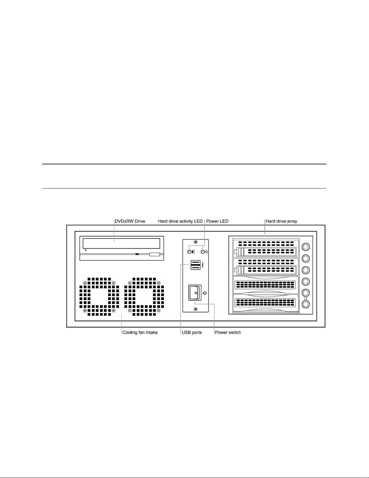
Front Panel Controls and LEDS
The front panel of the DVR unit contains the devices that will be commonly used for data
removal, retrieval, and backup replacement. The most common components and
buttons are shown below.
________________________________________________________________________________________________________
20
Page 21
CH 1 in CH 2 in CH 3 in CH 4 in CH 5 in CH 6 in CH 7 in CH 8 in CH 9 in CH 10 in CH 11 in CH 12 in CH 13 in CH 14 in CH 15 in CH 16 in
1 2 3 4 5 6 7 8 9 10 11 12 13 14 15 16
CONTROL
1 2 3 4 5 6 7 8 9 10 11 12 13 14 15 1 6
COM
SENSOR
ON
OFF
ON
OFF
CH 1 Out CH 2 Out CH 3 Out CH 4 Out CH 5 Out CH 6 Out CH 7 Out CH 8 Out CH 9 Ou t CH 10 Out CH 11 Out CH 12 Out CH 13 Out CH 14 Out CH 15 Out CH 16 Out
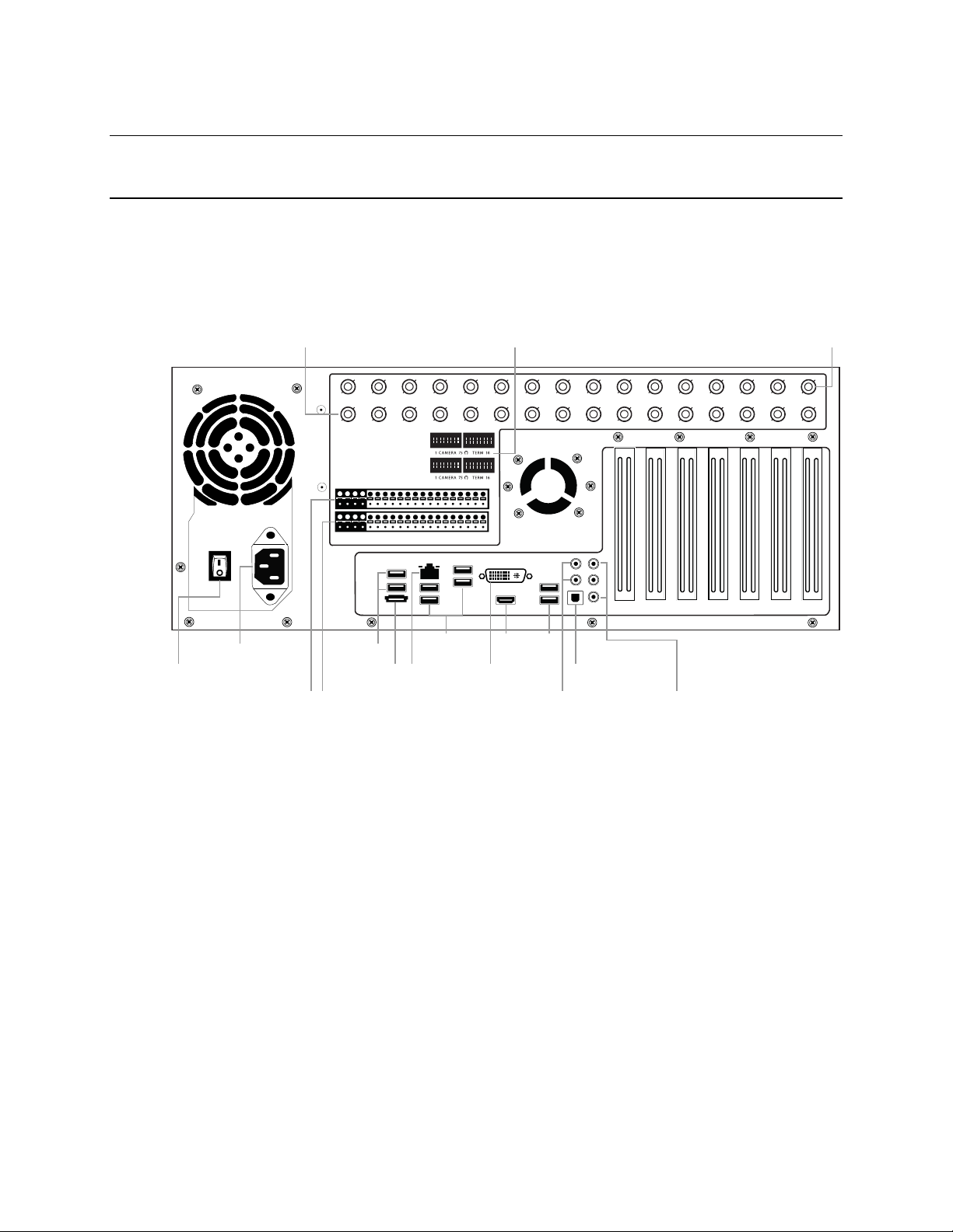
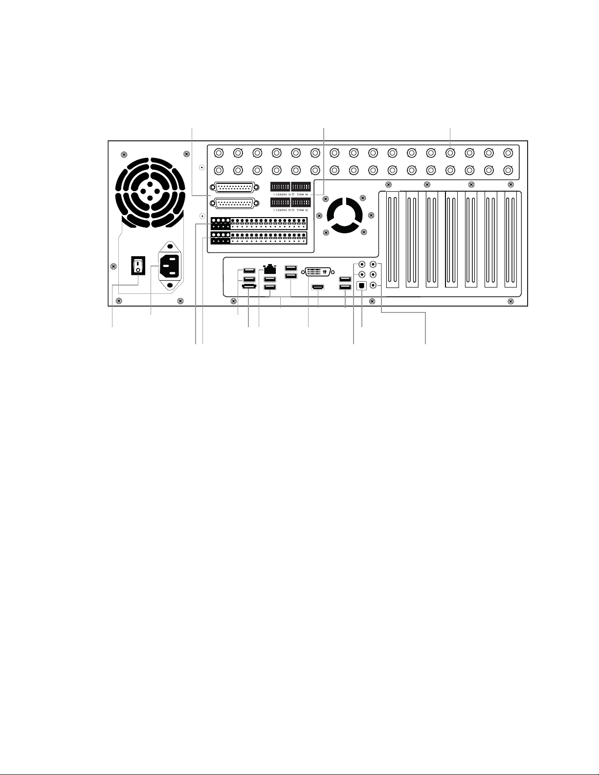
AC power
Secondary power switch
Looping outputs (BNC) Looping output termination Video inputs (BNC)
Sensor inputsControl outputs
Optical output
5.1 Surround sound
USB USB HDMI
DVINetworkeSATA Line in – line level
Speaker out
Microphone in – not used
USB
Rear Panel Connectors
The rear panel of the recorder contains the connectors used to attach cameras,
sensors, and relays to the recorder. Below are diagrams that outline the location and
description of each connector.
8/16 Channel
Fusion IV DVR User Guide
________________________________________________________________________________________________________
Document 800-05305V1 Rev B 21
10/11
Page 22
Controls and Connections
CH 1 in CH 2 in CH 3 in CH 4 in CH 5 in CH 6 in CH 7 in CH 8 in CH 9 in CH 10 in CH 11 in CH 12 in CH 13 in CH 14 in CH 15 in CH 16 in
1 2 3 4 5 6 7 8 9 10 11 12 13 14 15 16
CONTROL
1 2 3 4 5 6 7 8 9 10 11 12 13 14 15 1 6
COM
SENSOR
ON
OFF
ON
OFF
CH 17 in CH 18 in CH 19 in CH 20 in CH 21 in CH 22 in CH 23 in CH 24 in CH 25 in CH 26 in CH 27 in CH 28 in CH 29 in CH 30 in CH 31 in CH 32 in
BNC A
BNC B
AC power
Secondary power switch
BNC looping output cable adapter Looping output termination Video input (BNC)
Sensor inputsControl outputs
Optical output
5.1 Surround sound
USB USB
NetworkeSATA Line in – line level
Speaker out
Microphone in – not used
USB
AC power
Secondary power switch
BNC looping output cable adapter Looping output termination Video input (BNC)
Sensor inputsControl outputs
Optical output
5.1 Surround sound
USB USB
NetworkeSATA Line in – line level
Speaker out
Microphone in – not used
USB
HDMI
DVI
32 Channel
________________________________________________________________________________________________________
22
Page 23
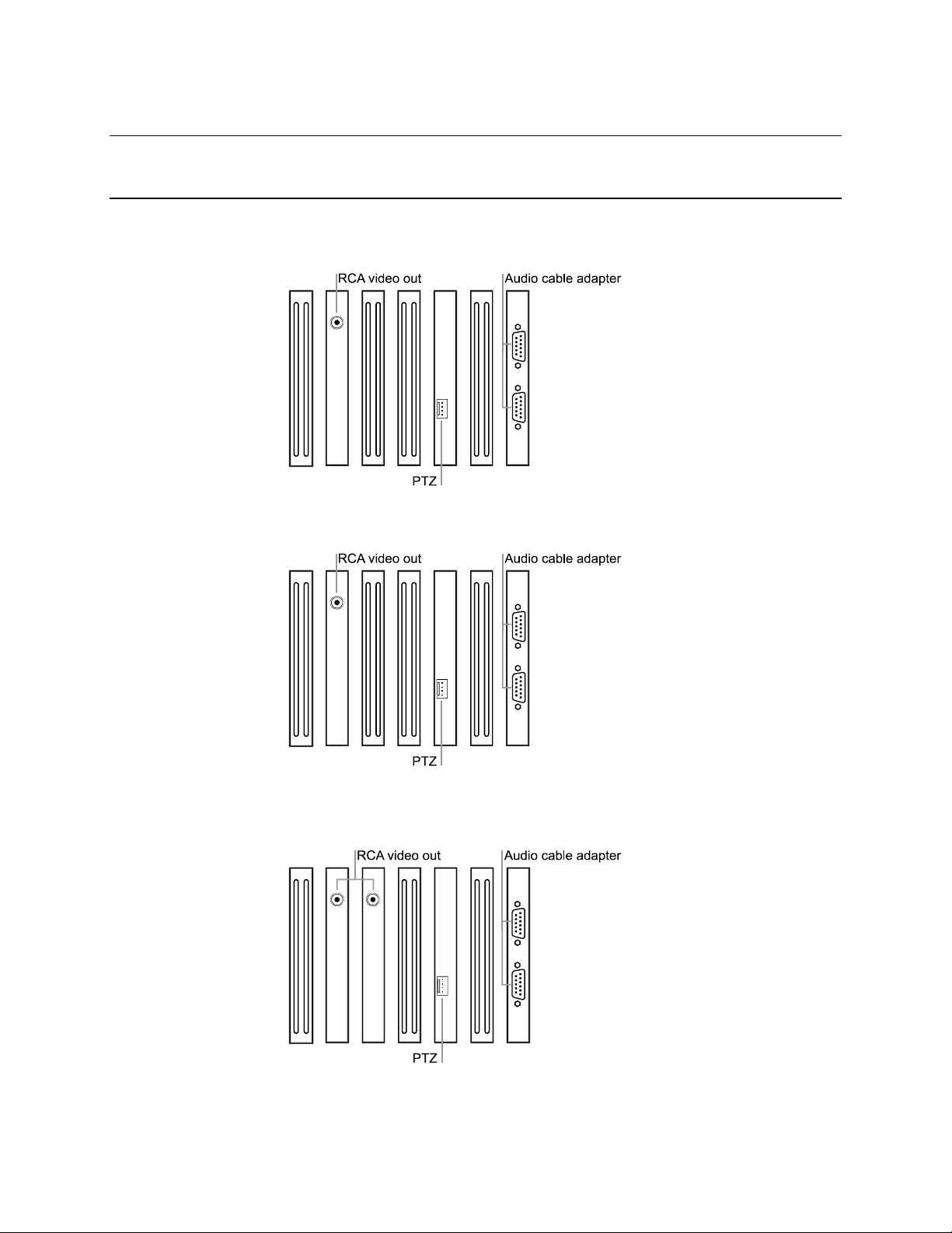
Card Configurations
120R IPS 16 Channel
Fusion IV DVR User Guide
240 IPS 8/16 Channel
240 IPS 32 Channel
480 IPS 16 Channel
________________________________________________________________________________________________________
Document 800-05305V1 Rev B 23
10/11
Page 24
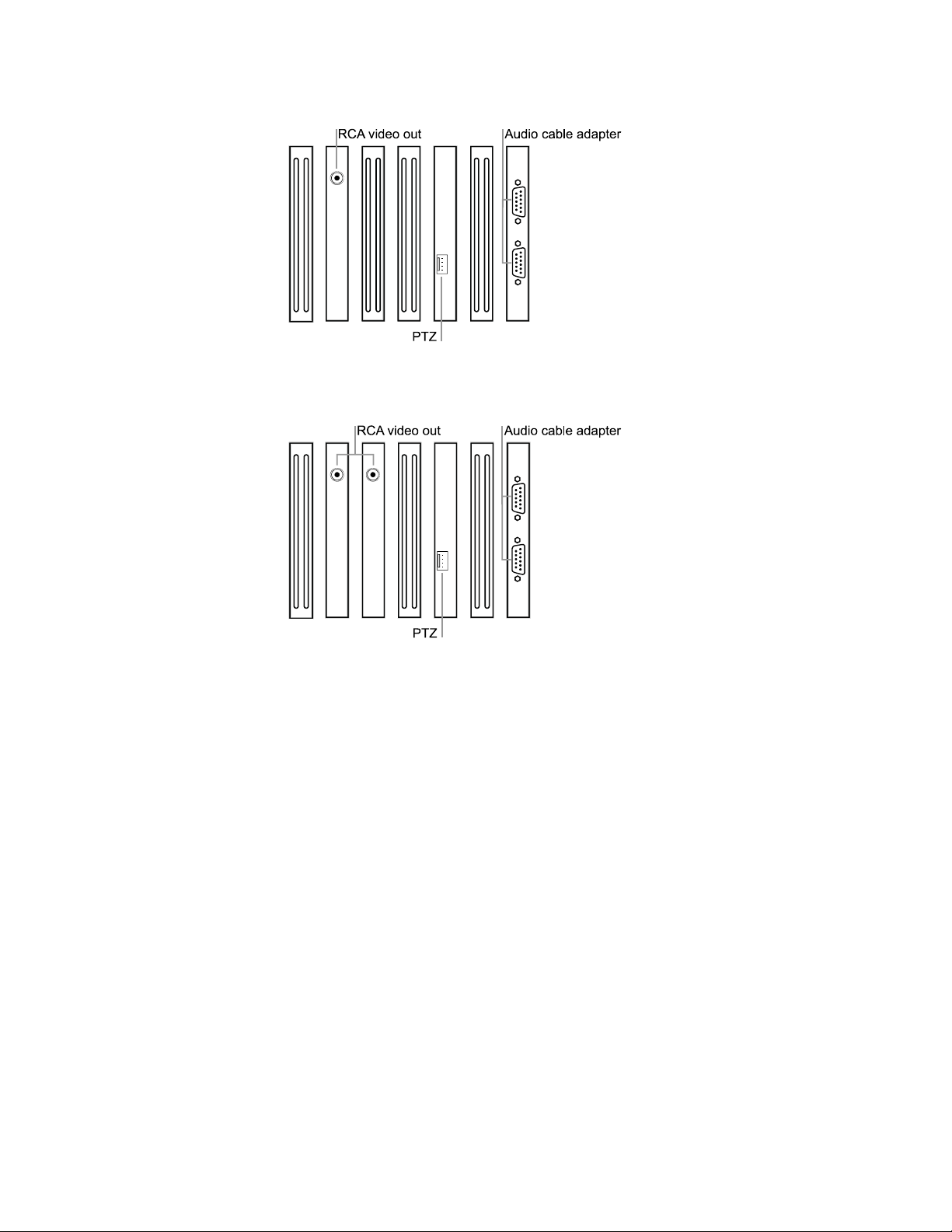
Controls and Connections
480 IPS 32 Channel
________________________________________________________________________________________________________
24
Page 25
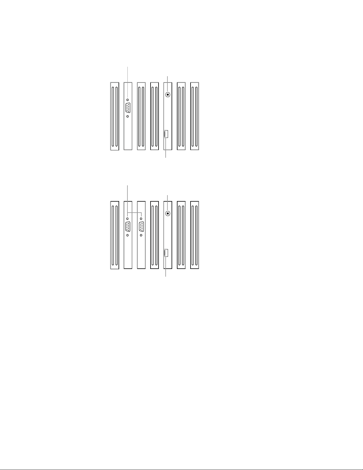
240 IPS 8 Channel H-Series Model
RCA video out
PTZ
Audio cable adapter
RCA video out
PTZ
Audio cable adapter
480 IPS 16 Channel H-Series Model
Fusion IV DVR User Guide
________________________________________________________________________________________________________
Document 800-05305V1 Rev B 25
10/11
Page 26
Controls and Connections
8
6
9
Getting Started
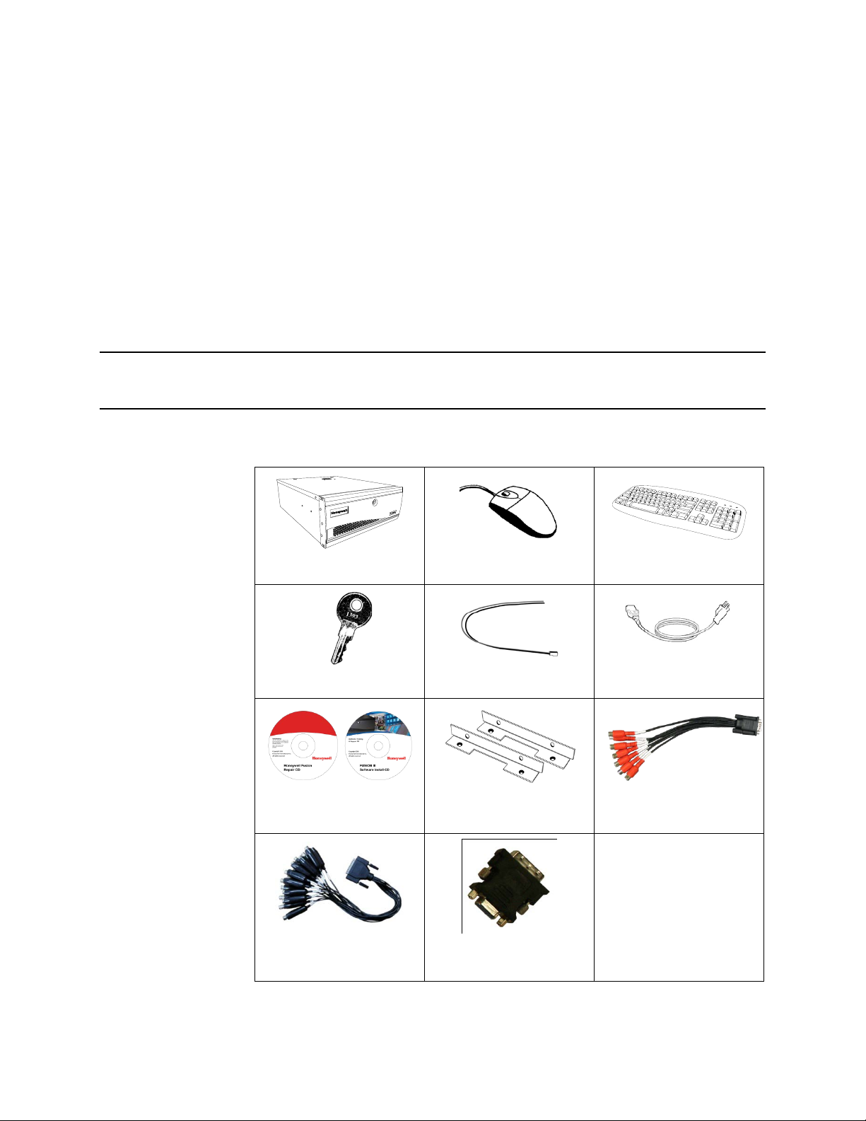
Identifying Included Components
Honeywell’s Fusion DVRs come with a mouse, keyboard, selected software and cables.
Identify the following components to make sure everything has been properly included
with the new DVR. If any of the following items are missing, contact your dealer.
DVR Mouse Keyboard
DVR Key PTZ Adapter Power Cord
DVR Repair/Software Disc
16 Channel Video Looping
Output Cable*
Rack Mount Attachments
8 Channel Audio Input
with 4 Mounting Screws
DVI-I to VGA adapter
Cable
* Video Looping Output Cable included with the 32 Channel models only.
________________________________________________________________________________________________________
26
Page 27

Keyboard Setup
To attach the keyboard to the recorder, plug the end of the Keyboard into a USB port
located on the back of the machine.
Fusion IV DVR User Guide
Mouse Setup
To attach the mouse to the recorder, plug the end of the mouse into a USB port located
on the back of the machine.
The mouse uses a cursor called a pointer. Pointers come in many different shapes but
are most commonly shaped like an arrow.
The mouse has two buttons: a left button and a right button. Quickly pressing and
releasing one of these buttons is called clicking. Sometimes you will need to doubleclick – or click the same button twice quickly.
In this manual:
Click means to position the mouse cursor over an item and to single click the left
button.
Right click means to position the mouse cursor over an item and to single click the
right button.
Double-click means to position the mouse cursor over an item and to click the left
button twice.
Select means to position the mouse cursor over a radio button, checkbox, or list item
and click on it.
The scroll wheel in between the two buttons is used for added navigation functionality.
By moving the wheel with index finger (scrolling), quickly move through multiple pages,
lines, or windows. The wheel may also function as a third button allowing the user to
quickly click or double-click an icon or a selected item
Scroll Button / Third Button
Right Button
Left Button
________________________________________________________________________________________________________
Document 800-05305V1 Rev B 27
10/11
Page 28
Controls and Connections
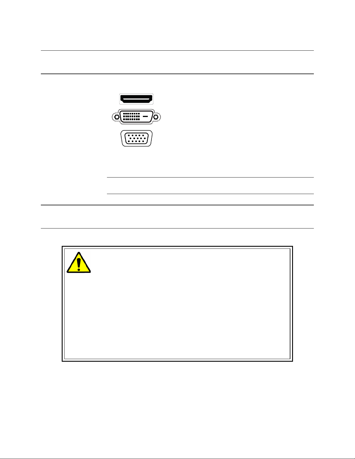
Monitor Setup
The recorder has the following connections available to attach a monitor.
Power Setup
Attach the monitor or monitors to the rear of the recorder using the cable supplied by
the monitor manufacturer. Refer to the monitor manual for detailed information on how
to setup and use it.
Note The monitor must be capable of having a screen resolution of 1024 x 768 and
display colors of at least 32 Bit
WARNING:
To reduce the risk of electrical shock or damage to the equipment:
Do not disable the power grounding plug.
The grounding plug is an important safety feature.
If the electrical plug you are using does not have a ground plug receptacle
contact a licensed electrician to have it replaced with a grounded electrical
outlet.
Plug the power cord into a grounded (earthed) electrical outlet that is easily
accessible at all times.
Disconnect the power from the computer by unplugging the power cord either
from the electrical outlet or the computer.
HDMI Output To TV / Digital Monitor
DVI -I Output To TV / Digital Monitor
Connect adapter to DVI output
DVI to SVGA Adapter
to connect an analog VGA
Monitor.
________________________________________________________________________________________________________
28
Page 29
CH 1 in CH 2 in CH 3 in CH 4 in CH 5 in CH 6 in CH 7 in CH 8 in CH 9 in CH 10 in CH 11 in CH 12 in CH 13 in CH 14 in CH 15 in CH 16 in
CH 1 Out CH 2 Out CH 3 Out CH 4 Out CH 5 O ut CH 6 Out CH 7 Out CH 8 Out CH 9 Ou t CH 10 Out CH 11 Out CH 12 Out CH 13 Out CH 14 Out CH 15 Out C H 16 Out
CH 1 in CH 2 in CH 3 in CH 4 in CH 5 in CH 6 in CH 7 in CH 8 in CH 9 in CH 10 in CH 11 in CH 12 in CH 13 in CH 14 in CH 15 in CH 16 in
CH 1 Out CH 2 Out CH 3 Out CH 4 Out CH 5 Out CH 6 Out CH 7 Out CH 8 Out CH 9 Ou t CH 10 Out CH 11 Out CH 12 Out CH 13 Out CH 14 Out CH 15 Out C H 16 Out
CH 1 In CH 2 In CH 3 In CH 4 In CH 5 In CH 6 In CH 7 In CH 8 In CH 9 In CH 10 In CH 11 In CH 12 In CH 13 In CH 14 In CH 15 In CH 16 In
CH 17 In CH 18 In CH 19 In CH 20 In CH 21 In CH 22 In CH 23 In CH 24 In CH 25 In CH 26 In CH 27 In CH 28 In CH 29 In CH 30 In CH 31 In CH 32 In
Making Connections
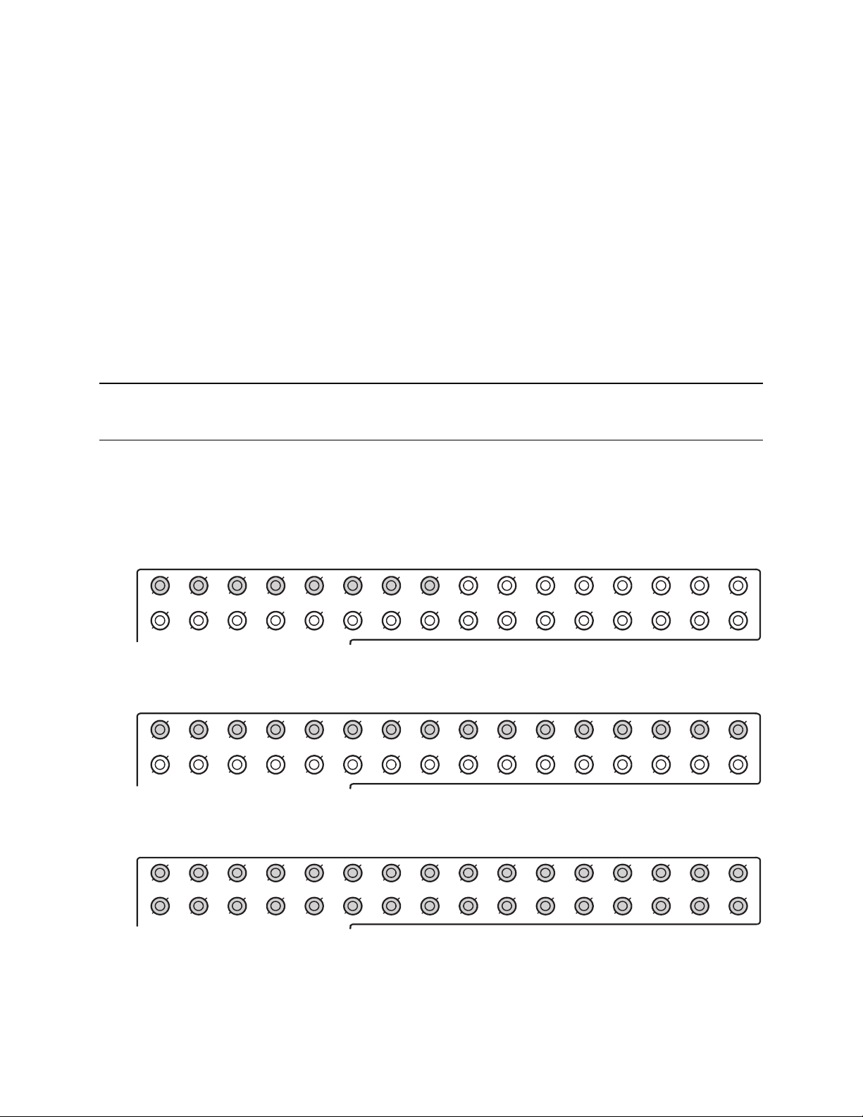
Connecting a Video Source
There are different types of Video Sources that can be plugged into the recorder
including DVD players, VHS players, and CCTV Cameras. The back of the recorder
contains up to 32 video inputs depending on the recorder model. The connectors use
the BNC standard.
Fusion IV DVR User Guide
8 Channel
16 Channel
32 Channel
The video inputs are 75 Ώ BNC connectors. Plug one end into the video source (DVD,
Camera, etc.) and plug the other end into the desired BNC input on the recorder.
________________________________________________________________________________________________________
Document 800-05305V1 Rev B 29
10/11
Page 30
Making Connections
COM
COM
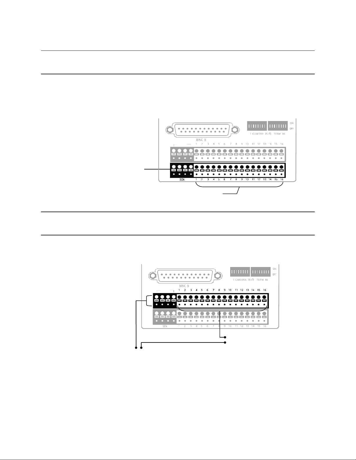
Connecting Sensors
Each recorder has up to 16 Sensor inputs. These inputs can be used with devices such
as infrared devices, motion device, glass breakage alarms, door and window trips, and
many more. The Sensors can be set to Normally Open or Normally Closed inside the
software.
There are 4 Common Grounds (-) and 16 sensor inputs (+). There is no power supplied
to the ports so an external power supply must be used if power is necessary.
Common
Ground
Sensor Inputs
Connecting Control Outputs
Each recorder has up to 16 Control Outputs. These outputs can be used to trigger
devices such as Sirens, Phone Dialers, Lights, and any other relay activated device.
There is no power supplied to the ports. Use an external power supply if necessary.
(+) (-)
External Power Supply (DC 12V)
Use 12V, below 300mA. For controlling lights or other devices, use another external
relay.
Maximum voltage is 24V AC @ 1 amp
Output uses a Form C Relay
Siren, Alarm, Outside Relays
________________________________________________________________________________________________________
30
Page 31

CH 1 in CH 2 in CH 3 in CH 4 in CH 5 in CH 6 in CH 7 in CH 8 in CH 9 in CH 10 in CH 11 in CH 12 in CH 13 in CH 14 in CH 15 in CH 16 in
CH 1 Out CH 2 Out CH 3 Out CH 4 Out CH 5 Out CH 6 Out CH 7 Ou t CH 8 Out CH 9 Ou t CH 10 Out CH 11 Out CH 12 Out CH 13 Out CH 14 Out CH 15 Out C H 16 Out
CONTROL
1 2 3 4
COM
SEN SO R
ON
O FF
ON
O FF
BN C A
BN C B
Looping Outputs
The 8/16 Channel recorders have up to 16 looping outputs. Depending on the
destination of the looping outputs, each one may have to be terminated.
The 32 Channel recorder has up to 32 looping outputs. Connect the included 16
Channel BNC Connector Cables to the 16 Channel Cable Adapter ports.
Fusion IV DVR User Guide
The video inputs/outputs are 75 Ώ BNC connectors. Make sure there is a video source
connected to the input and then connect a cable to the Channel Out on the BNC
Connector Cable. The looping outs can be connected to video monitors or combined
with adapters to connect to VCRs.
Looping Output Termination
When it is necessary to terminate a looping output, the recorder has built in termination
that allows users to select individual outputs. It is not always necessary to terminate the
output; it depends on the device to which you are connecting. As a rule, if the image
appears distorted or virtually unviewable, it likely needs to be terminated.
ON Not connected to a
monitor (Normal)
OFF Connected to a
monitor (Looped)
________________________________________________________________________________________________________
Document 800-05305V1 Rev B 31
10/11
Always leave the dipswitch set to the ON position when the Looping Outputs are not
used.
Page 32

Making Connections
Signal Line (+)
Connecting a PTZ Camera
Setting up a PTZ Camera is simple. The recorder comes preassembled with an internal
PTZ adapter. The cabling may be run up to 4,000 ft using 22 Gauge Twisted Pair.
It is important to understand how the PTZ connects to the recorder. The recorder
outputs an RS-232 signal and converts in to an RS-422/485 signal which is then sent to
the PTZ camera.
Attaching the 4-Pin Adapter
1. Locate the PTZ adapter cable
2. Connect the wires of the PTZ adapter to the
PTZ camera. The yellow wire should
connect to the RX+ on the camera and the
orange wire should connect to the RX-.
3. Connect the other end of the adapter to the
XVR unit as shown.
4. Assign the PTZ camera an ID number in
PTZ Setup that coincides with the number
assigned to the camera. This is normally
done utilizing a dip-switch configuration
method on the addressable dome.
Example: If the camera is plugged into
input number 5, set the PTZ unit to ID number 5.
RS-422
Signal Line (-)
Optional Components
To fully utilize the potential of the DVR, several optional Fusion components are listed
below. Contact a dealer for more information.
• Multiplex Video Output Card (MUX) • Internal Raid 5
• 4 Port Analog Output Card • External SATA Storage
• Gigabit 10/100/1000 NIC Adapter • External RAID 5 Storage
• Fusion Remote Video Software • SCSI Interface card
• Fusion Video Management Software • Performance package upgrade
• HVR/NVR Upgrade
________________________________________________________________________________________________________
32
Page 33

Turning On the Recorder
Once the cables and adapters have been properly connected it is time to turn on the
power. To turn on the power follow these steps:
1. Turn on the monitor and any external peripherals (ex. Printers, External Storage
Devices, etc.) connected to the recorder.
2. Turn on the Secondary Power Switch located in the rear of the recorder.
3. Turn on the main power switch located on the front of the recorder.
The recorder will run a series of self-tests. After two or three minutes a series of
messages may be displayed as the various hardware and software subsystems are
activated. Under normal circumstances you should not be asked to respond to these
messages. If you are asked to respond to the messages (adding a Printer, Monitor, etc
for the first time) follow the instructions carefully.
After this finishes, the Fusion recorder software should load automatically and bring you
to the main screen.
Turning Off the Recorder
Fusion IV DVR User Guide
To turn off the recorder, select the Exit button on the main screen and select Power Off.
The recorder will safely shutdown, it may take several minutes to shut down completely.
Caution Always be sure to follow the proper procedures when turning off the power
to the recorder. NEVER disconnect the power to the recorder while it is still
running or in the process of shutting down. Doing so can cause data loss,
file corruption, system instability and hardware failure
________________________________________________________________________________________________________
Document 800-05305V1 Rev B 33
10/11
Page 34

DVR Basics
DVR Basics
Setting the Time and Date
1. Exit to Windows by clicking Exit on the Live View screen and selecting Restart in
Windows Mode. (See the Live View screen section later in this chapter)
2. Open Windows Explorer. Do this by right-clicking the My Computer icon (located
on the top left hand corner of the Desktop) and select Explore.
3. Click on Control Panel to open it. If you do not see Control Panel listed, Click My
Computer to expand the folder tree.
4. Double-click Date and Time inside Control Panel.
5. Adjust the Date and Time.
6. When finished, close all open windows and restart the recorder.
________________________________________________________________________________________________________
34
Page 35

Accessing the DVR Utility
Exporting DVR Settings
Exporting DVR settings can help configure multiple DVRs quickly or reconfigure a unit
that has failed. Some things must be kept in mind when using this feature.
You cannot use this function on:
• DVRs that are different models.
• When upgrading from certain software versions. (This feature cannot be used
when upgrading from v2.x to v3.x)
Fusion IV DVR User Guide
1. Exit to Windows by clicking Exit on the Live View screen then and select Restart in
Windows Mode. (See the Live View screen section later in this chapter)
2. Open the DVR Utility window by clicking the Start button , clicking All
Programs, clicking Fusion, and then clicking vFormat.
3. Click Export in the System Setting tool section.
4. Select a location to save the settings file and click Save. The DVR Utility will export
the DVR settings and automatically close.
Importing DVR Settings
1. Exit to Windows by clicking Exit on the Live View screen then and select Restart in
Windows Mode. (See the Live View screen section later in this chapter)
2. Open the DVR Utility window by clicking the Start button
Programs, clicking Fusion, and then clicking vFormat.
3. Click Import in the System Setting Tool section.
4. Select the location of the settings file to import and click Open.
5. Click Yes to import the data file.
________________________________________________________________________________________________________
Document 800-05305V1 Rev B 35
10/11
, clicking All
Page 36

DVR Basics
Changing Video Format
1. Exit to Windows by clicking Exit on the Live View screen then and select Restart in
Windows Mode. (See the Live View screen section later in this chapter)
2. Open the DVR Utility window by clicking the Start button
3. Select the appropriate video setting from the list in the Video Setting section –
4. Click Set.
Live View screen
Each time the recorder starts, the program defaults to the Live View screen. The
following diagram outlines the buttons and features used on the Live View screen. You
should become familiar with these options as this is the screen that will be displayed the
majority of the time.
, clicking All
Programs, clicking Fusion, and then clicking vFormat.
NTSC or PAL..
Current Date & Time
Menu Buttons
Displays
Connected Users
Status of/Activates
Control Outputs
Camera Display Buttons
________________________________________________________________________________________________________
36
Status of/Activates
Alarm Sensors
Page 37

Live Camera Options
Right-click a camera on the Live View
screen to display these options:
• Full Screen
• Instant Recording
• Search In Live
• Digital Zoom
Fusion IV DVR User Guide
________________________________________________________________________________________________________
Document 800-05305V1 Rev B 37
10/11
Page 38

DVR Basics
Current Recording Status
Camera View
Special Recording Status
Camera No. and Name
Recording Status Indicator
The camera status for each camera is displayed in the upper right corner on the Video
Display Area. The following are the different states for each camera:
Recording Displayed when the camera is currently being recorded to
Motion Detection Displayed when a camera (set up for motion detection)
Display Displayed when the camera is currently not being
Special Recording
There are two types of Special Recording. Text is displayed on the camera indicating
what type of Special Recording is activated.
SENSOR Sensor is displayed when a sensor, associated with a given camera, is
activated.
the recorder.
detects motion.
recorded to the recorder.
________________________________________________________________________________________________________
38
INSTANT Instant Recording is a manual activation of the recording for the selected
camera. Regardless of the recording method, Instant Recording will start
the camera recording and also flag the video for future searches using
the Index Search feature. INSTANT is displayed when a user activates the
instant recording option. Double Right-Click the video display to activate
and deactivate the Instant Recording option.
Page 39

Screen Division Buttons
Note When viewing live video from Network Cameras, only 4CH will display at one
time..
Fusion IV DVR User Guide
Quad View
Nine Camera View
Camera Multi-View 1
Camera Multi-View 2
Camera Multi-View 3
Camera Multi-View 4
Full Screen
Auto-Sequence
Dual Monitor Camera Display Menu
When dual monitors are enabled, you can adjust the camera display for live view on the
secondary display. Move the mouse to the top of the screen and the camera display
menu will appear.
Displays cameras 1-4, 5-8, 9-12, 13-16, etc. in the
Video Display Area.
Displays cameras 1-9, 10-18, etc. in the Video
Display Area.
Displays the first 16 cameras in the Video Display
Area.
Displays a grouping of the first 7 cameras in the
Video Display Area.
Displays a grouping of the first 10 cameras in the
Video Display Area.
Displays a grouping of the first 15 cameras in the
Video Display Area.
Displays the current camera display configuration
full screen.
Sequences through the Screen Divisions sets of
4, 9, or 16 cameras.
________________________________________________________________________________________________________
Document 800-05305V1 Rev B 39
10/11
Page 40

DVR Basics
Custom Live View Divisions
Customize your Live View screen by changing the order of the cameras. Each screen
division can be individually customized but a camera can only be displayed once (once
in 4 camera view, once in 9 camera view, etc). Both analog and IP video cameras can
be moved.
Create custom live view divisions:
1. On the Live View screen click Setup, and then click the General tab.
2. Click Sequence Setting.
3. Drag and drop cameras from the Channel List to the desired location within the
Division Group (4 Division, 9 Division, 16 Division).
Channel
List
Division Group
________________________________________________________________________________________________________
40
Page 41

Setup Options
Setup Overview
The Setup options allow optimization of the DVR by adjusting things like camera names,
recording schedules and more. It is extremely important to setup the DVR correctly for
several reasons:
• Recording Schedules –Increase the amount of pertinent recorded video that is
• DVR Access – By setting up the access passwords, the user has better control
• Camera Naming – By naming each camera, the location and any other pertinent
• Adjusting Camera Color – Optimize the clarity and detail that is recorded by
Fusion IV DVR User Guide
saved on the DVR by optimizing the recording schedule. Optimize the type of
recording done by adding motion detection to this as well, again increasing the
amount of useful video.
of the types of access any individual may have. This ensures the security and
integrity of the DVR.
information can be easily identified when viewing it in the Video Display Area.
adjusting each camera’s color settings.
________________________________________________________________________________________________________
Document 800-05305V1 Rev B 41
10/11
Page 42

Setup Options
Setup Screen
Setup Menu Options
Camera Setup
Assign names to each camera, adjust color and brightness.
Network Video
Register and add network video devices, and adjust basic settings.
Motion
Create up to 15 video detection areas,
General
Configure display options, alerts, intensive recording
Frames
Set the Images Per Second for each camera.
Recording Schedule
Create custom recording schedules for each channel, sensor, and special days.
Sensor
Assign sensor names, set to Normally Open or Normally Closed.
Network
Assign network settings.
Administration
Set permissions for users, export logs, adjust HDD storage
Information
View version numbers, save contact numbers, and view available HDD status.
PTZ
Set up preset positions, tour and assign protocols.
________________________________________________________________________________________________________
42
Page 43

Camera Setup
Fusion IV DVR User Guide
Define camera name
Displays live video from a
selected camera
Apply current settings to all cameras
Set Up New Camera
1. Attach camera to the rear of the DVR chassis.
2. Click Setup on the Live View screen.
3. Click Camera Setup to open the Camera Setup display.
4. Select the channel that corresponds with the new camera from the Select Camera
list.
5. Enter a name for the camera in the Camera Name box.
6. Adjust the Brightness, Hue and Contrast if necessary.
7. Click Apply when finished.
________________________________________________________________________________________________________
Document 800-05305V1 Rev B 43
10/11
Page 44

Setup Options
Network Video
Connected
Devices
Connecting a Network Device
Note Refer to the EQUIP Series Network IP camera user guide for detailed
information on setting up that camera using the Honeywell IP Utility
application.
Connecting Manually
1. From the Live View screen, click Setup.
2. Click Network Video.
3. Click the Add/Remove Device tab.
4. Select your network device from the Device Type list.
5. Type a Device Name.
6. Type the IP/URL address, Port#, User ID and Password of the device.
7. Click Add.
Automatic Camera Finder
________________________________________________________________________________________________________
44
Page 45
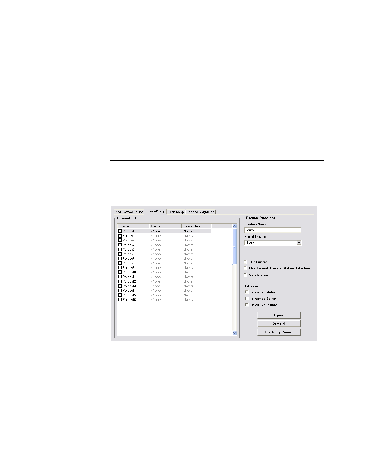
Connecting with Camera Finder
1. From the Live View screen, click Setup.
2. Click the Network Video tab.
3. Click the Add/Remove Device tab.
4. Click Find Cameras to automatically find all connected Network cameras.
5. Select the check box next to the desired camera.
6. Click Get Device.
7. Type the User ID and Password of the device.
8. Click Update.
Assigning a Network Device to a Channel
Note Fusion IV recorders support single stream IP camera operation. Dual stream
operation is not supported.
1. From the Live View screen, click Setup.
2. Click Network Video.
3. Click the Channel Setup tab.
Fusion IV DVR User Guide
4. Click an available channel on the Channel List.
5. Type the desired Position Name.
6. On the Select Device list, select the appropriate network device added previously.
7. If the device has PTZ capabilities, select the PTZ Camera check box to enable.
8. If the device displays wide screen video, select the Wide Screen check box to
allow it to display properly.
9. If supported, select the Use Network Camera Motion Detection check box.
10. Select Intensive Motion, Intensive Sensor, and/or Intensive Instant to increase
the recording rate on an event.
11. Click Apply to save your selections.
________________________________________________________________________________________________________
Document 800-05305V1 Rev B 45
10/11
Page 46

Setup Options
Assigning Audio Channels to a Network Device
1. From the Live View screen, click Setup.
2. Click Network Video.
3. Click the Audio Setup tab.
4. Click an available audio channel on the Channel List.
5. On the Select Device list, select a network device added previously.
6. To record the network audio select the Record Network Audio check box. The
audio channel will be available on the search screen.
7. To access the audio channel from the Live View screen, select the Enable Network
Video in Live View check box.
________________________________________________________________________________________________________
46
Page 47

Camera Configuration
The Camera Configuration tab displays information on all cameras (analog and
network) connected to the Fusion recorder
Fusion IV DVR User Guide
Enable/Disable Live Video
• To enable a network device to display as live video select the check box next to
• To disable live video for a network device, clear the check box next to the
Displaying More Columns
The Camera Configuration tab can be customized to display the information you use
most. Click Select Column to add or remove specific columns.
Capture FPS
Record FPS
Schedule
Manufacturer
Model
the Camera Name that you want available for live video display.
Camera Name.
IP Address
Port Number
Resolution
Record FPS
Frame Rate
Codec
Quality
PTZ
________________________________________________________________________________________________________
Document 800-05305V1 Rev B 47
10/11
Page 48

Setup Options
Accessing the Configuration Menu
Use the Fusion interface to access basic network device menu functions.
1. From the Live View screen, click Setup.
2. Click Network Video.
3. Click the Camera Configuration tab.
4. Highlight the desired camera.
5. Click Setup Network Device.
Motion Setup
The recorder allows the user to adjust several different Motion Settings and create
motion detection areas.
Apply Current Motion
Areas to all Channels
Reduces Analog Signal Noise
from Motion Detection
Regular Interval Recording
Regular Interval Recording allows users to record a single frame every few minutes or
hours even when there is no motion. This option is only available when Motion
recording is selected in the recording schedule.
To enable Regular Interval Recording:
1. Select the Regular Interval Recording check box.
2. Specify how often to take an image when no motion is occurring. System can be
set to as many as one image per second.
________________________________________________________________________________________________________
48
Page 49

Enable Sabotage Detection
The Camera Sabotage Detection feature will notify users that the field of vision of a
camera has been compromised, abruptly changed, or detects significant vibration.
To enable Sabotage Detection:
1. Select the Enable Sabotage Detection check box.
2. Set the threshold percentage to reduce false alarms.
3. Select the Beep on Detect check box – or – select a Relay to activate on detection.
Create a Motion Area
1. Click Motion in Setup.
2. Select a camera from the Select Camera list.
3. Select the Detect Detail Motion Area check box.
4. Click Clear.
5. Click Advanced Motion Area Setup.
6. Click a Motion Detection Area shape button.
Fusion IV DVR User Guide
7. Drag the mouse over the camera image.
Note To create a polygon shape, click the mouse at each point and double-click to
close the shape.
8. Click OK.
9. Move the sliders to adjust motion sensitivity and the noise filter.
10. Define the pre-alarm and post-alarm recording time for a motion event.
Pre Alarm – 0 > 50 Seconds [The number of seconds the recorder records before
motion is detected]
Post Alarm (MOTION) – 0 > 50 Seconds [The number of seconds the recorder records
after motion is detected]
________________________________________________________________________________________________________
Document 800-05305V1 Rev B 49
10/11
Page 50

Setup Options
General Setup
Adjust/Mute volume
Enable Live / Recording
Audio
Set up POS* integration
*Software Upgrade Necessary
Function
Beep on Login Fail Enables the DVR to beep continuously in response to a failed
login attempt. Only an authorized login will stop the beeping.
Sequence Setting Allows the video out picture to automatically cycle through
channels at a set speed. Example: .Cycle through channels 16 at four-second intervals.
Display Options
Use Full Screen Stretch the Fusion software to use the full monitor screen.
Display Size Select from available monitor display sizes. Use to correctly
display video on wide screen monitors.
Motion Detect on
Continuous
recording
Allows you to process and receive motion events and alarms
while recording in continuous mode. Also enhances search
capabilities when recording in continuous
Note Motion Detect on Continuous is not supported on IP
cameras.
________________________________________________________________________________________________________
50
Page 51

Voice Warning
The recorder allows users to play a sound file when either a Motion event or Sensor
event occurs. This file can be a custom created sound file that is unique to the
application. The selected WAV file is played through speakers attached to the recorder.
1. Click the Open Sound File icon to browse for a WAV file. The selected file will
display in the box on the left.
2. Click the Test icon to verify the audio file.
3. Select Activate on Motion, Activate on Sensor (Alarm), and or Activate on
Sabotage Detection to trigger the audio file.
Intensive Recording Overview
Fusion IV DVR User Guide
Test Sound File
Locate Sound File
The Intensive Recording option allows an increase of the Images Per Second of any
analog or IP camera recording in the MJPEG codec using sensor or motion activation.
H-series models use only sensor activation.
Enabling Intensive Recording
The Intensive Recording option is set up as an ‘All or Nothing’. This means that once
enabled (associated with sensors) all cameras that are associated with sensors will
activate the Intensive Recording.
To activate the Intensive Recording option, follow these steps.
1. Click the General tab.
2. Select the Intensive-on Sensor and/or Intensive on Motion check boxes.
3. Open Schedule under Setup Options. Select the Sensor option.
4. Enable the sensor by creating a schedule for it.
5. Click Apply and exit setup.
________________________________________________________________________________________________________
Document 800-05305V1 Rev B 51
10/11
Page 52

Setup Options
Video Loss Alarm
The DVR supports a Video Loss Alarm function which allows an Alarm Event to occur
when a camera loses its signal. The lost signal can be due to camera power failure to
the camera, the camera cable being cut or unplugged, or the camera being damaged in
some way.
In order to use Video Signal Loss detection, cameras must either be Enabled or
Disabled. This is because the DVR needs to know which cameras it should expect to
receive signals from. To enable camera(s), open Frame Setup, and set the Images Per
Second to anything above zero. By designating zero images per second the camera will
not be used by the DVR.
Volume
Activate Audio Alarm (BEEP)
When video loss occurs, an internal speaker on the DVR will sound an alarm.
Video Loss Alarm Log
When video loss occurs, the event is recorded in the DVR log.
Activate Alarm Output
When video loss occurs, an alarm (control) output is activated.
The volume control allows fine tuning of the volume settings on the recorder.
Volume Options:
• Speakers – Used to
adjust the volume for all
sound coming from the
system’s speakers
• System Sounds – Used
to adjust the volume for
the system sounds
exclusively.
________________________________________________________________________________________________________
52
Page 53

Connecting to a Wide Screen Display
1. Click Exit on the Live View screen and select Exit in Windows Mode.
2. Right-click the Desktop and select Screen Resolution.
3. From the Resolution list, select the proper resolution of the connected display.
Tip Refer to the display documentation for the proper resolution settings.
4. Click OK and confirm the change.
5. Double-click the Fusion Server icon on the Desktop.
6. Click Setup on the Live View screen and then click General.
7. Under Display Settings, select the Use Full Screen check box and then select the
correct resolution from the Display Size list.
8. Click Apply.
Connecting a Second Monitor
1. Click Exit on the Live View screen and select Exit in Windows Mode.
2. Right-click the Desktop and select Screen Resolution.
3. Click the secondary Live View screen and from the Multiple displays list click
Extend these displays.
4. Click Apply.
5. On the Resolution list, select the proper resolution of the connected display.
Fusion IV DVR User Guide
Tip Refer to the display documentation for the proper resolution settings.
6. Click OK and confirm the change.
7. Double-click the Fusion Server icon on the Desktop.
8. Click Setup on the Live View screen and then click General.
9. Under Function, select the Dual Monitor check box.
10. Click Apply.
________________________________________________________________________________________________________
Document 800-05305V1 Rev B 53
10/11
Page 54

Setup Options
Cameras
Auto Sequence Setting
Auto Sequencing is available either in the Live View screen when Auto Sequencing has
been enabled or when a Spot-Monitor out signal is used to display on a spot monitor.
Auto Sequencing conveniently displays video channels at specified intervals and
sequences through each selected channel.
Enable
Sequencing
Screen Division Options
Enable All
Custom Mode
Create non-standard screen divisions
Skip 0 FPS Channel
Sequence skips cameras with no video signal
Create Custom Auto Sequence
1. Open General setup and click Sequence Setting.
2. Click individual cameras in the left pane or click Select All to include all cameras in
the sequence.
3. Select an Interval time (in seconds) to display each screen in the sequence.
4. Select screen division options for appropriate cameras.
Select interval between switching cameras
________________________________________________________________________________________________________
54
Page 55

Frame Setup
Fusion IV DVR User Guide
The Frame Setup menu allows configuration of the IPS, resolution, quality, and
sensitivity of camera channels. When configuring the IPS sliders the BLUE slider
represents the IPS the DVR will record during intensive recording and have available for
transmitting to remotely connected systems. The RED slider represents the IPS that will
be recorded by the DVR under normal recording conditions.
The total IPS of all blue sliders may not exceed the recording IPS of the DVR. The IPS of
a red slider may not exceed that of the blue slider for the same channel. The dual sliders
allow configuration of the DVR to record at a lower IPS while still being able to transmit
at a higher IPS to remote connections.
Ex. If a camera channel is set to 25 IPS (blue) and 7 IPS (red), the DVR will record at 7
IPS and users viewing live video remotely can receive up to 25 IPS.
Note The RED IPS record slider cannot exceed the BLUE IPS capture slider.
Note The Software will not allow the maximum available Frames to be exceeded.
Frame Select
Blue Slider: Sets the IPS recorded during intensive recording and available for viewing
on a remote client PC.
Red Slider: Sets the IPS recorded by the DVR during normal recording.
Resolution: Affects the total number of frames per second that are available.
Codec: Select the appropriate codec for each camera (MJPEG, MPEG-4, H.264)
Video Quality: Lower quality video has a smaller file size but appears more pixilated.
Sensitivity: Sets the Keyframe refresh rate. Adjusting this setting can have negative
effects on video quality.
Note Do not change the default setting unless instructed by a system administrator.
________________________________________________________________________________________________________
Document 800-05305V1 Rev B 55
10/11
Page 56

Setup Options
Sensitivity
Video Quality
Standard Models
Camera Channel
Reset to Default Settings
Compression Codec
No. of Recording
Frames Selected
Frame Select
Recording Resolution
Note Using H.264 software compression significantly increases the processing load
on the Fusion recorder. If maximum analog IPS is desired in addition to IP
video recording or multiple remote clients, Fusion engineering recommends
the addition of the upgraded system CPU (DVR-CPUUPG).
________________________________________________________________________________________________________
56
Page 57

H-Series Models
Video Quality
Frame Select
Output to Video Out Display
Fusion IV DVR User Guide
Reset to Default Settings
Display Time of
Selected Channels
Camera Channel
No. of Recording
Frames Selected
Recording Resolution
________________________________________________________________________________________________________
Document 800-05305V1 Rev B 57
10/11
Page 58

Setup Options
Maximum IPS Table
IPS Breakdown for Each Resolution (NTSC)
Resolution CCTV 480 IPS Models 240 IPS Models H-Series Models
360x240 1CIF 480 IPS 240 IPS 480 IPS
720x240* 2CIF 240 IPS 120 IPS 480 IPS
720x480** 4CIF 120 IPS 60 IPS 480 IPS (D1)
* Frames recorded in 720x240 are twice the size of the standard 360x240. When
recording at 720x240, each frame assigned to the channel will use 2 of the total frames
available.
** Frames recorded in 720x480 are four times the size of the standard 360x240. When
recording at 720x480, each frame assigned to the channel will use 4 of the total frames
available.
IPS Breakdown for Each Resolution (PAL)
Resolution CCTV 400 IPS Model 200 IPS Model H-Series Models
360x288 1CIF 400 IPS 200 IPS 400 IPS
720x288* 2CIF 200 IPS 100 IPS 400 IPS
720x576** 4CIF 100 IPS 50 IPS 400 IPS (D1)
* Frames recorded in 720x240 are twice the size of the standard 360x240. When
recording at 720x240, each frame assigned to the channel will use 2 of the total frames
available.
** Frames recorded in 720x480 are four times the size of the standard 360x240. When
recording at 720x480, each frame assigned to the channel will use 4 of the total frames
available.
32 Channel Frame Allocation
32 channel models utilize two capture cards. When configuring cameras and allocating
frames, the total frame rate for the recorder is split between each capture card. Please
reference the chart below for available frames for each grouping of channels.
Resolution Channels 480 IPS Models 240 IPS Models
360x240
720x240
720x480
1 to 16 240 IPS 120 IPS
17 to 32 240 IPS 120 IPS
1 to 16 120 IPS 60 IPS
17 to 32 120 IPS 60 IPS
1 to 16 60 IPS 30 IPS
17 to 32 60 IPS 30 IPS
________________________________________________________________________________________________________
58
Page 59

Schedule Setup
Creating a customized schedule is important to maximize the efficiency of the DVR. The
Fusion DVR offers numerous options to allow for a wide variety of different needs and
requirements.
Fusion IV DVR User Guide
Schedule Number The Schedule Number is a group of settings. Up to 32
schedules can be created. Think of the schedules as
transparency paper with words written on them. When placed
one on top of another, the words can still be seen from the
layers below. These schedules allow a powerful detailed
recording schedule to be created.
Special Day
Recording Schedule
Alarm Options These are advanced options that send alarm events (either
Power Off Options Allows the user to specify time frames for turning off and
Customize a schedule for a particular day, such as a Parade
Day, Holiday, etc.
motion or sensor) to the remote alarm monitor software and
FVMS.
Tip To send motion events to FVMS, select both Motion
Event and Map Alarm check boxes.
restarting the DVR automatically.
________________________________________________________________________________________________________
Document 800-05305V1 Rev B 59
10/11
Page 60

Setup Options
Default Schedules
Default Schedule 1
All cameras are set to: 8AM-5PM. Continuous recording 5PM-8AM Motion recording
Default Schedule 2
All cameras are set to: Motion recording 24 hours/day, 7 days/week.
Camera 1 associated to sensor input 1
Camera 2 associated to sensor input 2
Camera 3 associated to sensor input 3, etc.
Note Default Schedule 1and Default Schedule 2 are not configured for use with
Day of the Week
The Day of Week is the day of the week for which the schedule is being edited. If WED
is checked, Wednesday’s schedule is being edited.
The Single Selection Mode button allows selection of multiple days at once.
By selecting the Single Selection Mode button placing multiple checks in the boxes is
allowed, thereby selecting multiple days simultaneously.
sensors/alarms.
Clicking on Single Selection Mode will change the button to Multi Selection Mode. This
allows you to select multiple days to configure at once.
Creating a Simple Schedule (By Example)
Creating schedules is easy with a little experience. In the following example, the steps
for creating a simple schedule for cameras 1 to 4 are detailed.
The schedule will be as follows:
• MON-FRI (9AM-5:59PM) all 4 cameras will record using MOTION recording.
• MON-FRI (6PM-8:95AM) all 4 cameras will record using CONTINUOUS
recording.
• SAT-SUN (12AM-11:59PM) all 4 cameras will record using MOTION recording.
Using these examples, a total of 3 schedules will be created.
________________________________________________________________________________________________________
60
Page 61

Fusion IV DVR User Guide
Step 5
Step 1
Step 2
Step 3
Steps 1-6: Schedule cameras 1-4 to record on MOTION from 9:00am-5:59pm
Monday through Friday.
1. Select Sch01 from the Schedule Number list. (This should already be selected by
default)
2. Click the Single Selection Mode button.
3. Select the MON, TUE, WED, THU, and FRI days of the week check boxes.
4. On the Sch01 line on time selector grid, highlight hours 09-17. Click Set.
5. Click Camera buttons 1-4 until the green Motion buttons are selected.
6. Click Apply to save.
Step 4
________________________________________________________________________________________________________
Document 800-05305V1 Rev B 61
10/11
Page 62

Setup Options
Step 10
Step 7
Steps 7-11: Schedule cameras 1-4 to record on CONTINUOUS from 6:00pm-
8:59am Monday through Friday.
7. Select Sch02 from the Schedule Number list.
8. On the Sch02 line again, highlight the hours 18-23 (for 6:00pm-midnight) and click
Set.
9. On the Sch02 line on time selector grid, highlight the hours 00-08 (for midnight to
8:59am) and click Set.
10. Click Camera buttons 1-4 until the maroon Continuous buttons are selected.
11. Click Apply to save.
Step 9
Step 8
________________________________________________________________________________________________________
62
Page 63

Fusion IV DVR User Guide
Step 16
Step 12
Step 13 & 14
Steps 12-17: Schedule cameras 1-4 to record on MOTION from
12:00am-11:59pm Saturday and Sunday
12. Select Sch03 from the Schedule Number list.
13. Select the SAT and SUN check boxes.
14. Clear all other Day of Week check boxes
15. On the Sch03 line on the time selector grid, highlight hours 00-23
and click the Set button.
16. Click Camera buttons 1-4 until the Green Motion buttons are selected.
17. Click Apply to save.
Step 15
________________________________________________________________________________________________________
Document 800-05305V1 Rev B 63
10/11
Page 64

Setup Options
Scheduling Sensors and Relays (By Example)
It is easy to add advanced recording functionality using Sensor Inputs and Relay
Outputs.
SENSOR - Sensor Inputs can be programmed to instantly start one or more cameras
recording when an alarm occurs. These alarm events can also activate Relay Outputs as
desired.
RELAY OUTPUT - Relay Outputs can be set to activate when motion alarms or sensor
alarms occur.
The schedule example will be as follows:
• SUN-SAT (12AM-11:59PM) Cameras 1 and 2 will be activated on Sensor #3
and/or Sensor #5, which will then activate Relay Output #7 and #13.
• SUN-SAT (12AM-11:59PM) Camera 3 will be set to Record on MOTION.
When motion occurs it will activate Relay Output #7 and #10.
• SUN-SAT (12AM-11:59PM) Sensor #6 will activate Relay Output #8 when an
alarm occurs. This event will NOT cause any cameras to record.
To do this, a total of 3 schedules will be created.
________________________________________________________________________________________________________
64
Page 65

Fusion IV DVR User Guide
Step 5
Step 1
Step 2
Step 3
Step 6
Step 7
Steps 1-8: Schedule cameras 1 and 2 to be activated on Sensor # 3 and/or
Sensor #5 which will then activate Relay Output #7 and #13.
1. Select Sch01 from the Schedule Number list. (This should already be selected by
default.)
2. Click the Single Selection Mode button.
3. Select the SUN, MON, TUE, WED, THU, FRI, and SAT check boxes.
4. On the Sch01 line (time selector grid), highlight the hours 00-23 and click Set.
5. Click Camera buttons #1 and #2 until the Red Sensor buttons are selected.
6. Click Sensor buttons #3 and #5.
7. Click Relay buttons #7 and #13.
8. Click Apply to save.
Step 4
________________________________________________________________________________________________________
Document 800-05305V1 Rev B 65
10/11
Page 66

Setup Options
Step 11
Step 9
Step 12
Steps 9-13: Schedule camera 3 to record using MOTION. When Motion occurs it
will activate Relay Output #7 and #10.
9. Select Sch02 from the Schedule Number list.
10. On the Sch02 line (time selector grid), highlight the hours 00-23 and click Set.
11. Click Camera button #3 until the green Motion button is selected.
12. Click Relay buttons #7 and #10.
13. Click Apply to save.
Step 10
________________________________________________________________________________________________________
66
Page 67

Fusion IV DVR User Guide
Step 14
Step 17
Step 16
Steps 14-18: Schedule Sensor #6 to act ivate Relay #8 when an Alarm occurs.
Note This will not trigger any cameras to record.
14. Select Sch03 from the Schedule Number list.
15. On the Sch03 line (time selector grid), highlight the hours 00-23 and click Set.
16. Click Sensor button #6.
17. Click Relay button #8.
18. Click Apply to save.
Step 15
________________________________________________________________________________________________________
Document 800-05305V1 Rev B 67
10/11
Page 68

Setup Options
Verifying a Recording Schedule
1. Select a single day of the week using the selection check box to the left of the
specified day.
2. Identify the schedule (or schedules) that have specific hours of the day highlighted
in light blue color. The horizontal axis of the schedule grid corresponds to the 24
hours of each day.
3. After verifying that all hours of the selected day are covered by at least one of the
32 independent schedules (vertical axis of schedule grid) now look to the lower half
of the schedule interface.
4. In the Schedule Number list, select the schedule(s) that were defined above for the
current day and verify, in each schedule number, that the correct cameras are set
to Continuous, Motion or Sensor based recording.
Note If a specific camera should not be recorded on a given day/schedule
combination, set the camera to “Not Selected” - a white “X”.
5. Repeat this process for each of the 7 days of the week until certain that the desired
recording method is configured for each day.
________________________________________________________________________________________________________
68
Page 69

Sensor Setup
Sensor/Control Names
(IP) Sensors
Fusion IV DVR User Guide
The Sensor setup window allows you to enable, disable and configure Sensors and
Relays (Control Outputs).
Enter Custom
Configure Hybrid
Associate Sensor w/ PTZ Presets
Open the On-Screen Keyboard
Configure Sensor Response
1. Click Setup on the Live View screen.
2. Click the Sensor tab.
3. Click to select NO or NC (Normally Open or Normally Closed) for the desired
sensor.
4. Enter the Delay time to define the number of seconds after the sensor is tripped
until the relay is activated.
Tip Associate sensors and relays with cameras when creating a recording
schedule.
5. Click Apply.
________________________________________________________________________________________________________
Document 800-05305V1 Rev B 69
10/11
Page 70

Setup Options
Activate PTZ Preset on Sensor
Create a PTZ Preset Position. See instructions in the PTZ Setup chapter.
1. Click Setup on the Live View
screen.
2. Click Sensor.
3. Click Sensor Preset.
4. Select the desired camera
from the Channel list.
5. Select the appropriate Sensor
from the list.
6. Select the preconfigured PTZ
Preset from the list.
7. Click Set. A list of configured
Sensor Presets will display in
the box below.
8. Repeat for additional sensors.
9. Click OK to close the Sensor
Preset window.
Hybrid Sensor Setup
This interface is used to link Hard Contact Sensor Inputs from supported Network
Devices to the recorder software.
________________________________________________________________________________________________________
70
Page 71

Network Setup
Fusion IV DVR User Guide
Network Setup allows the user to adjust settings such as Ports, setup emergency PPP
information for use with the Emergency Agent and enable Remote Access.
Enable 1-way audio from remote client to DVR
Enable RS-232 Keyboard
Network Setup
Time Out Value When attempting to connect to the DVR, if the connection does
not succeed during the timeout period (seconds), the
connection will be terminated.
Emergency Port Used to connect to the Alarm Monitor software.
Center Port Used to connect to the Fusion remote software. This port must
be specified in the Fusion Remote Software to connect to the
DVR.
Image Port Used to transfer the video to the Fusion remote software.
Search Port Used to transfer search information to the Fusion remote
software.
Upgrade Port Used to upgrade software via a remote connection.
Note If connecting to the DVR through a firewall, the
above ports must be open to incoming and
outgoing traffic.
________________________________________________________________________________________________________
Document 800-05305V1 Rev B 71
10/11
Page 72

Setup Options
Web Function
HTTP Port Used to transfer the DVR Interface via the Internet to the Web
Viewer. Default 80.
Internet Port Used for Data communication between the DVR and the Web
Viewer. Default 4006.
Live Port Used to transfer video via the Internet when Web Viewer is
enabled. Default 4007.
Health Check Port Enables FVMS to receive information regarding the health of
the DVR.
Resolution By setting the resolution low, the images will be sent faster,
however, the image quality will be reduced considerably. When
set to Original, full quality video will be sent [720 x 480 (NTSC)
720 x 576 (PAL)]. The Original setting is very bandwidth
intensive.
Transport Setup
Transport Rate Throttles the bandwidth on the DVR. This option is based on
percentages of images sent. These settings affect the quality
and speed of the video that is sent to the remote clients.
Administration
Select Date
Log Data
Advanced Configure the Transmit size on a per channel basis.
Export Log Data (1 to 7 days)
________________________________________________________________________________________________________
72
Page 73

Disk Management
The Disk Management window is a native Windows function. This window displays the
partition scheme and health status of the Hard Disk Drives in the recorder. This window
is often used to troubleshoot a recorder, or verify the amount of Hard Drive storage
installed. For more information about Disk Management, consult a Windows 7 manual.
Fusion IV DVR User Guide
________________________________________________________________________________________________________
Document 800-05305V1 Rev B 73
10/11
Page 74

Setup Options
Setting up DDNS
Enable DDNS
Dynamic Domain Name System (DDNS) is a service that provides a static address to
simplify remote connection to the recorder. This service is most useful for installations
where the WAN (public) IP address is dynamic (changes from time to time). Most public
IP addresses are dynamic unless a static address has been specifically ordered from
the internet service provider.
To enable this functionality of the recorder, follow the steps below:
1. Click Setup on the Live View screen and log in as Administrator if prompted.
2. Click The Administration tab.
3. Click Program Management (ETC) and enter the Administrator password when
prompted.
4. Click Show (to the right of The agent program for DDNS).
5. Select the Enable DDNS check box.
6. Enter the ID, Password, and Hostname specified on the DDNS document shipped
with your DVR.
Set the IP Address
Note Ensure the DVR has an IP address by setting it statically. The Network settings
may need to be changed. If you are not sure of the correct values, contact the
individual or department responsible for network administration at the site.
To set the IP address of the recorder, follow the steps below:
7. On the Live View screen, click Exit and choose Restart in Windows Mode.
8. On the desktop, right-click Network and click Properties.
9. In the Network and Sharing Center, click Local Area Connection.
10. Click Internet Protocol (TCP/IP) and then click Properties.
11. Select Use the following IP address.
12. Enter the following values (or as specified by the department responsible for
network administration).
a. IP Address: The first three sets of numbers should match the router’s local IP
address and the last set should be a unique number between 1-254.
b. Subnet Mask: This should match the router’s setting (commonly 255.255.255.0
for 192.X addresses and 255.0.0.0 for 10.X addresses).
c. Default Gateway: This is the router’s internal IP address. Once DDNS is
configured, the router the DVR connects to will need to be configured to forward
ports 80 and 4000 to the IP address of the DVR.
For further instruction on this process, visit
http://www.portforward.com/english/routers/port_forwarding/routerindex.htm
Select the correct model of router, and follow the instructions. Once DDNS and port
forwarding have been configured, the recorder will be accessible from any remote site
by entering the HOSTNAME into the address bar of Internet Explorer or the IP Address
field in the Remote Software.
________________________________________________________________________________________________________
74
Page 75

User Management
The User Management Console allows the administrator to create, edit, and delete user
accounts. Each user account can be assigned different privileges to limit the usage of
the recorder system. Users can be given administrator privileges by enabling all rights,
however only the true administrator account can log into the User Management
Console.
Fusion IV DVR User Guide
Enable Auto Log
Add a New User
Log Off User after x Minute(s) of
Note The Delete User button immediately deletes the user – use cautiously.
1. From the Live View screen, click the
Administration tab.
2. Click User Management.
3. Click Add User to open the User window.
4. Enter a User Name and Password.
5. Enable appropriate Permissions.
6. Select Cameras and Audio channels to hide
from the user.
7. Assign a User Rank.
8. Click OK to save changes and close the
window.
________________________________________________________________________________________________________
Document 800-05305V1 Rev B 75
10/11
Page 76

Setup Options
User Rank
The User Ranking structure allows the option to assign a privilege system (1-10 where
one has the most rights) to users of the recorder Software. For example. Since only
one user is allowed to use the PTZ controls at any one time, an administrator with a
higher rank can kick another user out and take control of the PTZ.
The User Rank option affects:
SETUP ACCESS - The recorder Software can only have 1 user accessing Setup at any
given time. A user with a higher rank will kick another user out and then open Setup.
NOTE: User settings will NOT be saved when a user with a higher ranking logs in.
PTZ CONTROL - The recorder SOFTWARE can only have 1 user using the PTZ controls
at any given time. A user with a higher rank will kick another user out and then open the
PTZ controls.
1. From the Live View screen, click Setup.
2. Click the Administration tab.
3. Click User Management.
4. Enter the Administrator password and click OK.
5. Select a user from the Select User box and click Update User.
6. Set the user’s rank using the User Rank list and click OK to save changes.
Changing the Administrator Password
1. Inside the Administration tab, click User Management. When the prompt appears,
click Change Password.
2. Enter the new password and click OK.
Default Administrator Password
The default administrator login is:
User: Administrator
Password: <blank>
Log Management
The Log Management window provides the user the options to overwrite log files or
schedule log deletion.
________________________________________________________________________________________________________
76
Page 77

Set up Log Management Options
1. From the Administration tab, click Log Management.
2. Select the check box to enable the Log File Overwrite Option.
Set Log Overwrite
a) Select Overwrite and define the size of the log file cache.
Set Log Cache Size
a) Select Do Not Overwrite and define the number of days to maintain log files.
Manually Delete Log Files
a) Select the type(s) of log file to delete. System Log, Event Log, Alarm Log.
b) Click Delete All.
3. Click OK to save the settings and close the window.
Fusion IV DVR User Guide
________________________________________________________________________________________________________
Document 800-05305V1 Rev B 77
10/11
Page 78

Setup Options
Status Check / Email
General
1. Click Setup on the Live View
screen.
2. Click the Administration tab.
3. Click Status Check/Email.
4. Select the Enable Email Alarm
check box.
5. Enter a From Name and e-mail
Address.
Note This name and address will
6. Enter the SMTP information for
the “From” email account.
Contact the email administrator
for this information if necessary.
7. If using a secondary e-mail account select the Use Secondary SMTP check box
and complete the SMTP information.
8. Click Test to check settings.
9. Click Apply when finished.
appear in the From line of
the email alert message.
Users
1. Set up the General tab first.
2. Click the Users tab.
3. Select the type of Event to send
email on.
4. Enter the User Name and E-
mail Address of an email
recipient.
5. Click Add.
6. Repeat for additional recipients
and types of events.
Note A separate email
notification for each type of
event must be set up for a
single recipient to receive
notifications for each type
of event.
7. Click Apply when finished.
________________________________________________________________________________________________________
78
Page 79

Storage Check
1. Set up the General and Users
2. Select the Use Storage Check
3. Define the number of minutes.
4. Select an Alert Option, Beep or
5. Click Apply.
Recording Data Check
1. Set up the General and Users
2. Select the Recording Data
3. Define the number of hours
4. Select the Action Method.
5. Click Apply.
Fusion IV DVR User Guide
tabs first. (see previous sections)
check box.
Popup Message, if desired.
tabs first. (see previous sections)
Check check box.
between data checks.
SMART Information
The SMART Information tab displays
Hard Drive information.
________________________________________________________________________________________________________
Document 800-05305V1 Rev B 79
10/11
Page 80

Setup Options
SMART Alert
Alarm Event
1. Set up the General and Users
tabs first. (see previous sections)
2. Select the Enable SMART
Alarm check box.
3. Define the number hours
between SMART checks.
4. Select the type of SMART event
to trigger an action.
5. Define the maximum HDD
temperature.
6. Select an action method.
7. Click Apply.
1. Set up the General and Users
tabs first. (see previous sections)
2. Select the Use Email Alarm
check box.
3. Define the number of minutes
between recording data checks.
4. Select Motion and/or Sensor to
send and alert on that type of
event.
5. Click Apply.
6. Click Close to return to the
Administration tab.
Data Management
Data Management is available for select regions where operators must delete data after
a set number of days. If you need to purge your video data, and this feature is not
enabled on your Fusion recorder, contact Technical Support.
________________________________________________________________________________________________________
80
Page 81

Information
Fusion IV DVR User Guide
The Information display allows users to define the site code necessary for connecting to
remote software, save comments relative to the recorder and store tech support and
contact number information.
Current Server Software Version
User-Defined Contact Numbers
Site Code: A user-specified unique identification name used by other recorder software
to identify the recorder. (Remote, Emergency Agent, FVMS, Digital Signature Verifier)
CBSN: Displays the serial number of an internal DVR hardware component.
Total HDD /Available HDD Space
Enter comments
________________________________________________________________________________________________________
Document 800-05305V1 Rev B 81
10/11
Page 82

Setup Options
Instant Recording
The Instant Recording feature allows users to manually initiate recording on a specific
camera, overriding the current schedule. When Instant Recording is activated the
recorder flags the clip as an event so Instant Recording instances can be found using
the Index Search
Instant Recording can be used, for example, when a suspicious object or person is
detected and the user wants to flag that section of video for easy retrieval at a later date.
Activate Instant Recording
1. From the Live View screen, double right-click the camera on which to enable instant
recording. An INSTANT label will be placed on the upper right corner of the video.
2. To turn the Instant Recording option off, double right-click the camera a second
time.
Searching ‘Instant Recorded’ Video
1. From the Live View screen click Search.
2. Click Index Search.
3. Select the Instant Recording option. See the Search chapter for more information.
________________________________________________________________________________________________________
82
Page 83

Search
Search Overview
The recorder has several options that allow the user to easily search through, and find,
a particular section of video. From Motion/Sensor indexing to calendar views
highlighting days with recorded video; the recorder is equipped to help the user quickly
find a specific video or event.
Fusion IV DVR User Guide
Note 16 Channel model shown below.
Actual Date/Time
Screen Division Buttons
Search Options
Play Controls
Search Date/Time
Select Cameras
Calendar Button
________________________________________________________________________________________________________
Document 800-05305V1 Rev B 83
10/11
Hour Minute Control
Page 84

Search
Play Controls
Rewind
Back Frame
Back Frame Moves video back one frame.
Rewind Rewinds video.
Play Plays video.
Forward Frame Moves video forward one frame.
Stop Stops video playback
Hour / Minute Controls
The Hour/Minute Control Bar allows a user to select the Hour and Minute using an easyto-use slide bar. The user can control the slide bar by clicking and dragging the slider or
using the scroll wheel on the mouse.
Stop
Play
Forward Frame
Brightness / Speed / Zoom
The Brightness and Zoom features can get the most out of the images. Adjusting
Brightness can brighten up an image to get more detail. Zoom can not only bring the
image up full screen but also Zoom into a particular area of the image.
Slow / Fast: Increases or decreases playback speed.
Brightness: Used to adjust the brightness of an image.
Zoom: Used to zoom in on an image.
Adjusting the Brightness of an Image
1. Select a single image to adjust by double-clicking on the desired image.
Multiple images cannot be adjusted at one time.
2. Move the Bright slide bar to the right or left to adjust the brightness.
3. Reset the brightness by clicking the Bright button.
________________________________________________________________________________________________________
84
Page 85

Zooming in on an Image
1. Select a single image to adjust by double-clicking on the desired image.
Multiple images cannot be adjusted at one time.
2. Move the Zoom slide bar to the right or left to zoom in or out of an image.
3. Reset the zoom by clicking the Zoom button.
Zooming in on a Portion of an Image
1. Right-click the area of interest on the image.
2. Repeated right-clicking will zoom in further.
3. Continue to right-click the image and the zoom will cycle back to the original size.
Adjust the Brightness of an Image
1. Select an image to adjust by double-clicking on the desired image. Multiple images
cannot be adjusted at one time.
2. Move the Brightness slide bar to the right or left to adjust the brightness.
3. Reset the Brightness by moving the slider back to the center of the bar.
Fusion IV DVR User Guide
Zooming in on an Image
1. Select an image to adjust by double-clicking on the desired image. Multiple images
cannot be adjusted at one time.
2. Move the Zoom slide bar to the right or left to zoom in or out of an image.
3. Reset the Zoom by moving the slider back to its original position on the bar.
Zooming in on a Portion of an Image
1. Right-click the area of interest on the image and select Zoom.
- or – Double-right-click the image.
2. Repeat to zoom in further.
3. Continue clicking the right mouse button and the image zoom will cycle back to the
original size.
Open Video from a Saved Location
Previously saved video clips or backup files can be searched for content. Find file by
date and time or by name.
1. Click Open to search for the saved file.
2. Select a file from the list of saved clips and backup files or search by start hour.
3. Click OK to open the saved file.
________________________________________________________________________________________________________
Document 800-05305V1 Rev B 85
10/11
Page 86

Search
Time Sync
The Time Sync option synchronizes a single channel of video to playback in real time.
Ordinarily the video may playback slower or faster depending on several factors,
including how many IPS recorded and number of cameras playing at the same time.
1. Select a single image to synchronize by double-clicking on an image.
2. Click Time Sync. The video will now playback in real time.
After Image Removal
The recorder is capable of recording video using one of three different resolutions.
When using the 720 x 480 resolution, two fields are mixed. Because of the timing gap
between the two fields, according to the standardized image rules, after image might
occur to high speed moving images. The Fusion recorder allows the user to remove
this by clicking the After Image Removal button.
Performing a Basic Search
There are several different types of searches that can be performed on the recorder. The
most basic involves selecting the date, time, camera, and clicking play.
1. Click the Calendar button to select a date.
2. Select a time by clicking the up and down arrows to the right of the time display.
3. Click OK.
4. Select one or more cameras.
5. Click Play. Video can be played forwards, backwards, or frame-by-frame.
Printing an Image
1. Using the Search screen, locate a frame to print.
Note Only one camera can be selected at a time for this function to work.
2. Click Print. A Print Options window appears. Depending on the printer being
3. Click Print to print the selected images.
Note The message “NO DEFAULT PRINTERS INSTALLED” will display if no printer
used, there may be several printing options available. Refer to the printer manual
for more information.
is installed.
________________________________________________________________________________________________________
86
Page 87

Daylight Saving Time
The recorder automatically adjusts for Daylight Saving Time changes. When the hour
“jumps forward” no video is lost because an hour is skipped. However when the hour
“falls back” there is a duplicated hour that under normal circumstances would be
recorded over. The Fusion recorder actually records both hours and allows the user to
select which hour to play if the need arises.
To access the ‘lost hour’:
1. From the Search screen, click the Calendar button.
2. Select the date when Daylight Saving time ‘lost’ an hour. The Daylight Saving
option appears.
3. To play back the ‘lost hour’, select the Daylight Saving check box and enter the
repeated hour in the time box.
4. Click OK to confirm the date and begin playing the video using standard search
features.
Fusion IV DVR User Guide
Save to JPG or AVI
The recorder can export single images in a JPG Image file format and save video clips
in an AVI format. Both JPG and AVI file formats are the most commonly used graphical
formats today. Virtually every computer offers some type of support for these file
formats which make them the most ideal formats to use.
JPG
Optimized for compressing full-color or grayscale photographic images, JPG images
are 24-bit (16.7 million color) graphics. Use JPG to export a single image or frame.
AVI
AVI image data can be stored uncompressed, but it is typically compressed using a
Windows-supplied or third party compression and decompression module called a
codec. AVI is used to export a video clip.
________________________________________________________________________________________________________
Document 800-05305V1 Rev B 87
10/11
Page 88

Search
To save a .jpg sill or .avi video clip:
1. From the Search screen, click Save.
2. Select the Export Type: Image File (JPG) or AVI File.
Note Different image format types provide different file-sizes, quality and
compatibility.
Image File
a) Select Quality (50>100). When size is not an issue, set the quality to 100.
AVI File
a) Enter the duration (seconds) to record. Although 100 is the longest time
displayed, a longer recording may be entered manually.
b) Select a Compression Codec. Each codec provides different levels of
quality, compatibility and file-size.
c) Select Quality - 50>100. When size is not an issue, set quality to 100.
3. Click Export to save file. The Cancel button exits the window without exporting file.
________________________________________________________________________________________________________
88
Page 89

Bookmarks
Fusion IV DVR User Guide
Use bookmarks to mark a video clip during a search. Export bookmarked data using
the Clip Backup feature.
1. Perform a search for the
desired video.
2. Stop playback at the
beginning of the desired clip.
3. Right-click the video and
select Start Bookmark.
4. Click the play button to
continue playback.
5. Stop playback at the end of
the desired clip.
6. Right-click the video at the
desired end point and select
End Bookmark.
7. Type a name to identify the
bookmark in the Title box.
8. Enter a memo or notes in the
More Information box.
9. You may also select additional channels to include video at different locations
recorded at the same time.
10. Click Create.
Modify Bookmarks
You can modify a previously
created bookmark to change
the start or end time of the
clip, add additional comments,
change the title, or add
additional cameras.
1. From the Search screen,
click Graphic Search and
then click Bookmark.
2. On the calendar, select
the date the desired
bookmarks were created.
3. Select the desired
bookmark from the list.
4. Make the desired change.
5. Click Modify.
6. When the modification is
complete, click Cancel to
close the window.
________________________________________________________________________________________________________
Document 800-05305V1 Rev B 89
10/11
Page 90
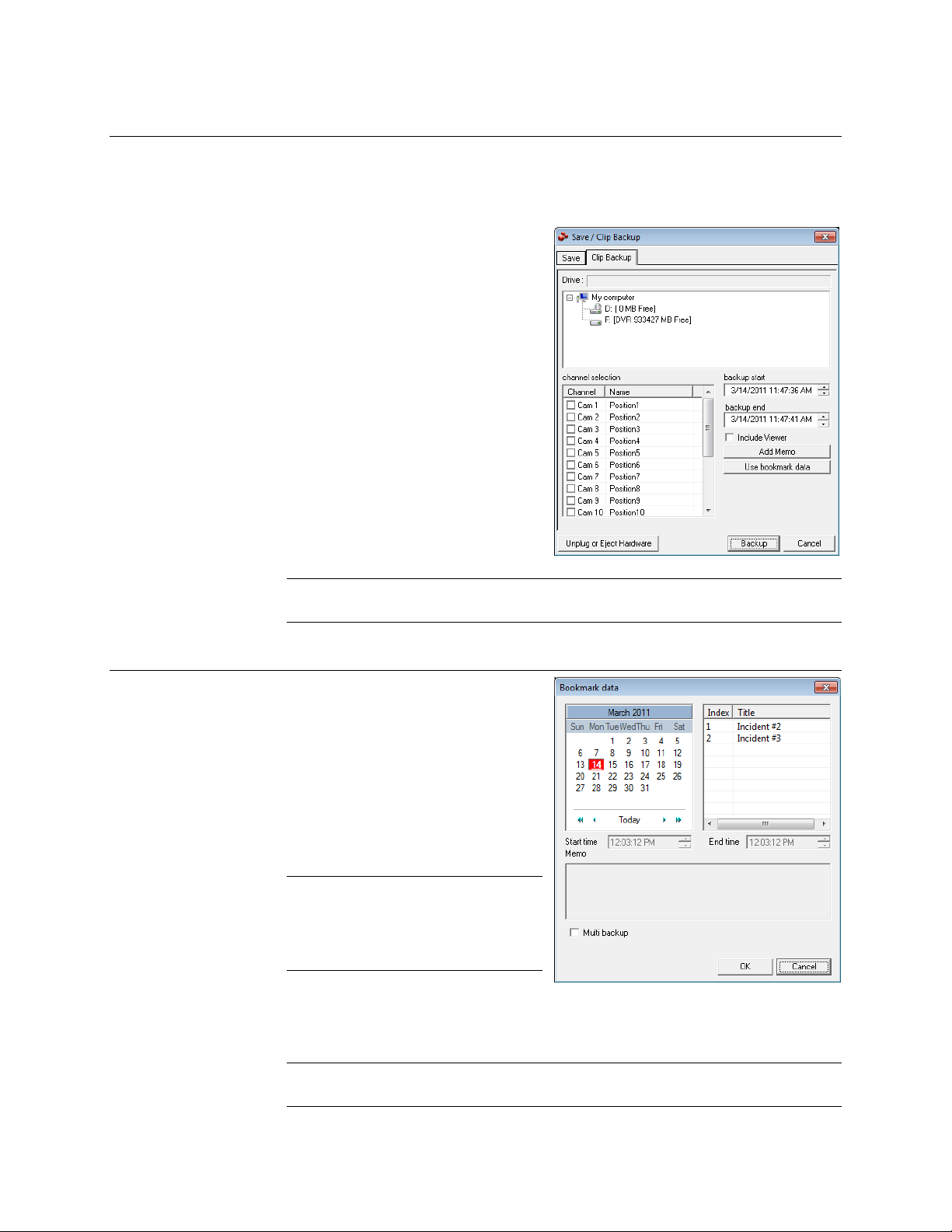
Search
Single Clip Backup
Along with the Save option, a single camera backup option is also included with the
Fusion software. The single Camera or Clip Backup allows the user to backup a single
camera without having to backup multiple cameras at a given time. The Clip Backup
option gives the users the ability to choose a backup time frame, choose a specific
camera, add memos, and even make a
copy for the Backup Viewer if needed.
1. From the Search screen, click
Save.
2. Select the drive from the file tree to
save data to. (Hard disk drive,
removable drive (USB), CD/DVD
drive)
3. Select cameras from the list.
4. Define the Start and End time of
the backup clip.
5. Select the Include Viewer check
box to include a copy of the
proprietary Backup Viewer
Software to view the clip on virtually
any Windows machine.
6. Click Add Memo to include
additional information.
7. Click Backup to start the backup.
Note If backing up to a removable USB device click the Unplug or Eject Hardware
button after backup is complete to safely remove the device.
Single Clip Backup Using Bookmark Data
1. From the Search screen, click the
Save button.
2. Select the drive from the file tree to
save data to. (Hard disk drive,
removable drive, CD/DVD drive).
3. Click Use Bookmark Data.
4. On the calendar, select the date the
desired bookmarks were created.
5. Select the desired bookmark from
the list.
Note To include multiple
bookmarks in a clip backup,
select the Multi Backup check
box before selecting the
desired bookmarks.
6. Type notes in the Memo box to
include additional information.
7. Click OK close the Bookmark data window.
8. Click Backup to start the backup.
Note If backing up to a removable USB device click the Unplug or Eject Hardware
button after backup is complete to safely remove the device.
________________________________________________________________________________________________________
90
Page 91

Time Event Occurred
Event Recorded on Camera #
Index Search
Using the Index Search can greatly decrease the amount of time spent searching
through saved video. The Index Search allows a user to perform a search based on
criteria such as Sensor, Motion and Instant Record events
Performing an Index Search
1. Click the Calendar button on the
Search screen to select the date
to search.
2. Click Index Search.
3. Select the cameras and sensors
to include in the search.
4. Select the Select Time check box
to define a specific period.
5. Select an event type to search
(Sensor, Motion, Instant
Record) or select the All Event
option.
6. Click OK. There may be a delay
while results are returned.
Results will be displayed in a
column on the left side of the
screen – Each line represents a
segment of video. If no results
are found, “NO IMAGE FOUND”
will appear in the column.
7. Once the results are displayed, double-click any one to play the associated video.
8. Once the desired image is found, apply it to the Main Search by clicking the Close
button at the bottom of the results column.
Fusion IV DVR User Guide
Index Search Results Display
________________________________________________________________________________________________________
Document 800-05305V1 Rev B 91
10/11
Image Display Area
Event Type:
M – Motion
S – Sensor
IR – Instant Record
Page 92

Search
1
2
3
4
5
10
9
8
7
6
11
12
13
14
15
16
17
21
22
18
19
20
23
24
1 2 3
4 5 6
1
6
1 Minute Increments
2
3
4
5 7
8
9
10
1 Hour Increments
10 Minute Increments
1 Minute Increments
1 Hour Displayed
10 Minutes Displayed
1 Day (24 Hours) Total
Preview Search
Preview Search can be used in a number of circumstances to quickly find an exact
moment where an event, such as a theft, occurred. The Preview Search gives a 24
Hour visual overview of a single camera by separating a 24 hour period (1 day) into 24
images, one image for each hour of the day. The search can then be further narrowed
down into ten minute increments and one minute increments by selecting one of the
images displayed.
These example images show how the Preview Search functions.
The first screen that appears has 24 images displayed. Each image represents the first
second of each hour. If there is no image recorded during that period then nothing will
be displayed.
When an hour is selected (by double-clicking on the image), a new screen appears with
6 images. Each of these images represents a 10 minute segment of video within the
selected hour.
Once a 10 minute segment is selected (by double-clicking on the image) the final
screen appears which breaks down that 10 minute segment into 1 minute increments
(10 images).
________________________________________________________________________________________________________
92
Page 93

Performing a Preview Search
1. Select a single camera by either turning off all cameras but one or double-clicking a
displayed image.
2. Click Preview Search. 24 images display. If there is no recorded video during a
portion of the day, “No Image” will be displayed where the image should be.
3. Refine the search by double-clicking on an image to select it. 6 images display. If
needed, return to the previous 24-image view by right-clicking on an image.
4. Refine the search by double-clicking on an image to select it. 10 images display. If
needed, return to the previous 6-image view by right-clicking on an image.
5. Double-click an image to select the 1-minute segment of video to play. A single
image displays. If needed, return to the previous 10-image view by right-clicking on
an image.
6. Use the Play controls to play the video of the selected segment.
7. To exit out of the Preview search with the current image still selected, click Preview
Search again to clear it.
Object Search
Fusion IV DVR User Guide
Object Search is a powerful search utility that is used to search a region on the video for
any motion changes. Results are neatly displayed and can be viewed quickly.
________________________________________________________________________________________________________
Document 800-05305V1 Rev B 93
10/11
Page 94

Search
Performing an Object Search
1. Perform a Basic Search. See the instructions on Performing a Basic Search.
2. Select a single camera, either by turning off all cameras but one or by double-
clicking a displayed image.
3. Click Object Search on the Search screen.
4. Click and drag the mouse on the video display to define a motion region area.
Resize by pulling on the small square boxes located on the outer perimeter of the
area.
5. Click Start Search, the Object Search Filter Information window will open
6. Select an End date/time. One hour is the default setting.
7. Adjust the sensitivity if necessary.
8. Click OK.
9. Select a motion event from the search results list displayed on the right
10. Click Apply to Main Search to display the selected image in the main Search
screen and to use play controls
11. To start a new object search using the original image, click Reload First Frame.
12. To exit Object Search without selecting an image, click Cancel.
________________________________________________________________________________________________________
94
Page 95

Status Search
Fusion IV DVR User Guide
The Status Search option displays video in graph format. (16 Channel Model Show)
Hours 0-23 (24 hours)
Cameras
Performing a Status Search
1. Click Status on Search Screen Display.
2. Click the calendar icon to select a day.
3. Click on an area of the blue recording block. Only one camera can be displayed at
a time.
4. Recorded video from the corresponding camera and time block will display above.
5. Use the mouse or arrow buttons to move through recording blocks and view video.
Recording Block
________________________________________________________________________________________________________
Document 800-05305V1 Rev B 95
10/11
Page 96

Search
Motion Search
The Motion Search provides a dynamic display of the levels of motion in recorded
video. Adjust the level of motion to only play clips of video at or above that level.
Tip To enable motion data to be saved for Motion search, ensure that you select
the following settings:
On the Motion setup page under Motion Regions, select the Detect Detail
Motion Area check box.
On the General setup page under Display, select the Motion Detect on
Continuous Recording check box.
Note Motion Search is only available for newly recorded video; it is not compatible
with video recorded prior to version 3.6.
Camera Information
Performing a Motion Search
1. From the Search screen select a camera. Motion Search can only be performed
on one camera at a time.
2. Click Graphic Search and then click Motion Search.
3. Click the calendar icon to select a day.
4. Adjust the motion level line.
5. Adjust the timeline display settings.
6. Click the play button to start playback.
Tip You can drag the blue line on the Timeline or motion level box to adjust the
time.
Motion Tolerance Level
Timeline
________________________________________________________________________________________________________
96
Page 97

Audio Playback
Audio is played back at 48,000Hz.
To play audio with the video:
1. Select a single camera by turning off all cameras but one using the Camera Select
2. Select a single audio channel to play. When an audio channel is selected, the Time
3. Click Play.
Tip When connecting speakers to the recorder for the first time, exit the Fusion
Fusion IV DVR User Guide
buttons. The audio buttons will be displayed.
Sync button will be automatically selected.
software to Windows mode before plugging in the speakers. This will ensure
that the speakers are detected properly.
________________________________________________________________________________________________________
Document 800-05305V1 Rev B 97
10/11
Page 98

Pan / Tilt / Zoom
Pan / Tilt / Zoom
Pan / Tilt / Zoom Overview
The PTZ controls within the recorder allow for powerful control over the cameras. This
can be extremely beneficial by increasing the usefulness of the recorded video. Using
the PTZ controls you can create custom preset configurations that can continuously
sweep across large areas.
Note PTZ setup and control is only available for supported video encoders with a
PTZ RS-485 pass-through.
Setting up a PTZ Camera
Setting up a PTZ Camera is simple. The recorder comes preassembled with an internal
PTZ adapter. The cabling may be run up to 4,000 ft using 22 Gauge Twisted Pair.
It is important to understand how the PTZ connects to the recorder. The recorder
outputs an RS-232 signal and converts it to an RS-485 signal which is then sent to the
PTZ camera.
Refer to the Connections section of this manual for information on connecting the PTZ
camera to the recorder.
________________________________________________________________________________________________________
98
Page 99

Enable the PTZ Settings
1. Inside the recorder PTZ Setup, select the PTZ camera using the Camera Channel
list.
2. Enable the PTZ functions of the camera by selecting the Enable Pan/Tilt check
box.
3. Select the appropriate Protocol and set the PTZ Driver Address and Serial Port
Settings (See Advanced PTZ Setup in this chapter).
Note The majority of major PTZ manufacture protocols are included in this software.
Refer to the Supported Protocols list in this manual.
4. Click Apply and then click Exit.
5. From the Live View screen, click PTZ (See the chapter on DVR Basics). The PTZ
Controller will open.
6. Select the PTZ camera to control by clicking on its video on the Live View screen.
The camera number will appear inside the PTZ controls.
7. Using the PTZ controls, move the PTZ around.
Fusion IV DVR User Guide
________________________________________________________________________________________________________
Document 800-05305V1 Rev B 99
10/11
Page 100

Pan / Tilt / Zoom
Advanced PTZ Setup
Note Preset and Tour options may vary depending on the camera
Creating and Viewing Preset Positions
A Preset Position is a user-defined location where the camera can be pointed, zoomed
in, and focused. Preset positions can be defined and labeled if the camera supports
this.
Creating a Preset
1. Inside Setup, click the PTZ tab and select a camera from the Channel list.
2. Select the Pan/Tilt Connection check box and select the appropriate PTZ protocol.
3. Under PTZ Status on Close, click Controller to open the PTZ graphical gontroller.
4. In the Preset box, select a Preset from the list to modify (a red box will appear
around the Preset).
5. Use the controls on the Graphical Controller to move the selected camera to the
desired position.
________________________________________________________________________________________________________
100
 Loading...