

Page 1

Fusion4 MSC-L
Installation & Operation Manual
Fusion4 MSC-L
Page 2

For service-related questions, contact:
T echnical Assistance Centre
Phone:
+1 800 423 9883 or
+1 215 641 3610
E-mail:
HFS-TAC-SUPPORT@honeywell.com
© 2021 - Honeywell International Inc.
Page 3

Table of Contents
CHAPTER 1 GENERAL. . . . . . . . . . . . . . . . . . . . . . . . . . . . . . . . . 1-1
1.1 Product Overview . . . . . . . . . . . . . . . . . . . . . . . . . . . . . 1-1
1.2 Functionality Overview . . . . . . . . . . . . . . . . . . . . . . . . . 1-3
1.3 Target Audience for this Manual . . . . . . . . . . . . . . . . . 1-3
CHAPTER 2 SAFETY . . . . . . . . . . . . . . . . . . . . . . . . . . . . . . . . . . 2-1
2.1 Safety Conventions. . . . . . . . . . . . . . . . . . . . . . . . . . . . 2-1
2.1.1 Warnings. . . . . . . . . . . . . . . . . . . . . . . . . . . . . . . . . . . . . . . . . .2-1
2.1.2 Cautions . . . . . . . . . . . . . . . . . . . . . . . . . . . . . . . . . . . . . . . . . .2-1
2.2 Safety Instructions for the MSC-L . . . . . . . . . . . . . . . . 2-2
2.2.1 General . . . . . . . . . . . . . . . . . . . . . . . . . . . . . . . . . . . . . . . . . . .2-2
2.2.1.1 EC Declaration of Conformity (for EU) . . . . . . . . . . . . . . . . . . .2-2
2.2.1.2 Control Drawings for FM & CSA . . . . . . . . . . . . . . . . . . . . . . . .2-2
2.2.1.3 Users. . . . . . . . . . . . . . . . . . . . . . . . . . . . . . . . . . . . . . . . . . . . .2-3
2.2.1.4 Additional Information . . . . . . . . . . . . . . . . . . . . . . . . . . . . . . . .2-3
2.2.1.5 Environmental Conditions . . . . . . . . . . . . . . . . . . . . . . . . . . . . .2-3
2.2.2 Operation . . . . . . . . . . . . . . . . . . . . . . . . . . . . . . . . . . . . . . . . .2-3
2.2.3 Maintenance and Troubleshooting . . . . . . . . . . . . . . . . . . . . . .2-3
2.2.4 Personal Safety. . . . . . . . . . . . . . . . . . . . . . . . . . . . . . . . . . . . .2-3
2.2.4.1 General . . . . . . . . . . . . . . . . . . . . . . . . . . . . . . . . . . . . . . . . . . .2-4
2.2.4.1.1 Opening the MSC-L . . . . . . . . . . . . . . . . . . . . . . . . . . . . . . . . . . . . . .2-4
2.2.5 Commissioning and Maintenance. . . . . . . . . . . . . . . . . . . . . . .2-4
2.2.5.1 Tools . . . . . . . . . . . . . . . . . . . . . . . . . . . . . . . . . . . . . . . . . . . . .2-4
2.2.6 Electrical . . . . . . . . . . . . . . . . . . . . . . . . . . . . . . . . . . . . . . . . . .2-4
2.2.6.1 Grounding . . . . . . . . . . . . . . . . . . . . . . . . . . . . . . . . . . . . . . . . .2-4
2.2.7 Accordance to Regulations . . . . . . . . . . . . . . . . . . . . . . . . . . . .2-6
2.2.7.1 Explosion Safety Limiting Values . . . . . . . . . . . . . . . . . . . . . . .2-6
2.2.7.2 Explosion Safety . . . . . . . . . . . . . . . . . . . . . . . . . . . . . . . . . . . .2-6
2.2.7.3 Low-Voltage Directive . . . . . . . . . . . . . . . . . . . . . . . . . . . . . . . .2-6
2.2.7.4 The MSC-L Labels . . . . . . . . . . . . . . . . . . . . . . . . . . . . . . . . . .2-7
2.3 Safety Instructions for the LAD . . . . . . . . . . . . . . . . . . 2-8
2.3.1 General . . . . . . . . . . . . . . . . . . . . . . . . . . . . . . . . . . . . . . . . . .2-10
2.3.1.1 EC declaration of conformity (for EU) . . . . . . . . . . . . . . . . . . .2-10
2.3.1.2 Control Drawings for FM & CSA . . . . . . . . . . . . . . . . . . . . . . .2-10
2.3.2 Explosion Safety . . . . . . . . . . . . . . . . . . . . . . . . . . . . . . . . . . .2-10
Part No.: 4418309_Rev11 Fusion4 MSC-L
Installation & Operation Manual 1
Page 4

Table of Contents
2.3.3 Commissioning . . . . . . . . . . . . . . . . . . . . . . . . . . . . . . . . . . . .2-10
2.3.4 Operation . . . . . . . . . . . . . . . . . . . . . . . . . . . . . . . . . . . . . . . .2-10
2.3.5 Maintenance and Troubleshooting . . . . . . . . . . . . . . . . . . . . .2-10
2.3.6 Additional Information . . . . . . . . . . . . . . . . . . . . . . . . . . . . . . . 2-11
2.3.7 Environmental Conditions . . . . . . . . . . . . . . . . . . . . . . . . . . . . 2-11
2.3.8 The LAD Labels . . . . . . . . . . . . . . . . . . . . . . . . . . . . . . . . . . .2-12
2.4 Safety Instructions for the IR Controller . . . . . . . . . . 2-13
2.4.1 General . . . . . . . . . . . . . . . . . . . . . . . . . . . . . . . . . . . . . . . . . .2-14
2.4.2 Precautions . . . . . . . . . . . . . . . . . . . . . . . . . . . . . . . . . . . . . . .2-14
2.4.2.1 EC declaration of conformity (for EU) . . . . . . . . . . . . . . . . . . .2-15
2.4.3 Installation. . . . . . . . . . . . . . . . . . . . . . . . . . . . . . . . . . . . . . . .2-15
2.4.4 Commissioning . . . . . . . . . . . . . . . . . . . . . . . . . . . . . . . . . . . .2-15
2.4.5 Operation . . . . . . . . . . . . . . . . . . . . . . . . . . . . . . . . . . . . . . . .2-15
2.4.6 Maintenance and Troubleshooting . . . . . . . . . . . . . . . . . . . . .2-15
2.4.7 Additional Information . . . . . . . . . . . . . . . . . . . . . . . . . . . . . . .2-16
2.4.8 IR Controller Labels . . . . . . . . . . . . . . . . . . . . . . . . . . . . . . . .2-16
2.5 Liability. . . . . . . . . . . . . . . . . . . . . . . . . . . . . . . . . . . . . 2-17
CHAPTER 3 SYSTEM DESCRIPTION . . . . . . . . . . . . . . . . . . . . . 3-1
3.1 Introduction . . . . . . . . . . . . . . . . . . . . . . . . . . . . . . . . . . 3-1
3.1.1 General . . . . . . . . . . . . . . . . . . . . . . . . . . . . . . . . . . . . . . . . . . .3-1
3.1.1.1 Transactions and Batches. . . . . . . . . . . . . . . . . . . . . . . . . . . . .3-1
3.1.2 Batch principle. . . . . . . . . . . . . . . . . . . . . . . . . . . . . . . . . . . . . .3-1
3.1.2.1 Batch Flow Stages . . . . . . . . . . . . . . . . . . . . . . . . . . . . . . . . . .3-2
3.1.3 Types of Blending . . . . . . . . . . . . . . . . . . . . . . . . . . . . . . . . . . .3-4
3.1.3.1 Straight Loading . . . . . . . . . . . . . . . . . . . . . . . . . . . . . . . . . . . .3-4
3.1.3.2 Ratio Blending. . . . . . . . . . . . . . . . . . . . . . . . . . . . . . . . . . . . . .3-4
3.1.3.3 Side Stream Blending . . . . . . . . . . . . . . . . . . . . . . . . . . . . . . . .3-4
3.1.3.4 Sequential Blending . . . . . . . . . . . . . . . . . . . . . . . . . . . . . . . . .3-5
3.1.4 Additive Injection. . . . . . . . . . . . . . . . . . . . . . . . . . . . . . . . . . . .3-6
3.1.5 Loading Principle. . . . . . . . . . . . . . . . . . . . . . . . . . . . . . . . . . . .3-6
3.1.5.1 Device loading capabilities . . . . . . . . . . . . . . . . . . . . . . . . . . . .3-8
3.1.6 Menu-based MSC-L Control . . . . . . . . . . . . . . . . . . . . . . . . . . .3-9
3.2 MID Compliance. . . . . . . . . . . . . . . . . . . . . . . . . . . . . . . 3-9
3.2.1 Introduction . . . . . . . . . . . . . . . . . . . . . . . . . . . . . . . . . . . . . . . .3-9
3.2.2 MID Approval Approach . . . . . . . . . . . . . . . . . . . . . . . . . . . . . .3-9
3.2.3 Component-level Requirements . . . . . . . . . . . . . . . . . . . . . . .3-10
Fusion4 MSC-L Part No.: 4418309_Rev11
2 Installation & Operation Manual
Page 5

Table of Contents
3.2.4 System-level Requirements . . . . . . . . . . . . . . . . . . . . . . . . . .3-13
3.2.5 The Fusion4 MSC-L . . . . . . . . . . . . . . . . . . . . . . . . . . . . . . . .3-13
3.3 System Architecture . . . . . . . . . . . . . . . . . . . . . . . . . . 3-14
3.4 FlexConn Modules. . . . . . . . . . . . . . . . . . . . . . . . . . . . 3-16
3.4.1 General . . . . . . . . . . . . . . . . . . . . . . . . . . . . . . . . . . . . . . . . . .3-16
3.5 Hardware Structure . . . . . . . . . . . . . . . . . . . . . . . . . . . 3-17
3.5.1 Housing. . . . . . . . . . . . . . . . . . . . . . . . . . . . . . . . . . . . . . . . . .3-17
3.5.2 Interior. . . . . . . . . . . . . . . . . . . . . . . . . . . . . . . . . . . . . . . . . . .3-19
3.5.3 Grounding Concept. . . . . . . . . . . . . . . . . . . . . . . . . . . . . . . . .3-20
3.6 PCB Layout . . . . . . . . . . . . . . . . . . . . . . . . . . . . . . . . . 3-24
3.6.1 PCB Details. . . . . . . . . . . . . . . . . . . . . . . . . . . . . . . . . . . . . . .3-25
3.6.1.1 CAN-HMI-MSC . . . . . . . . . . . . . . . . . . . . . . . . . . . . . . . . . . . .3-25
3.6.1.1.1 Functions . . . . . . . . . . . . . . . . . . . . . . . . . . . . . . . . . . . . . . . . . . . . .3-25
3.6.1.1.2 Component Locations. . . . . . . . . . . . . . . . . . . . . . . . . . . . . . . . . . . .3-27
3.6.1.2 CAN-ARM-MSC . . . . . . . . . . . . . . . . . . . . . . . . . . . . . . . . . . .3-29
3.6.1.2.1 Functions . . . . . . . . . . . . . . . . . . . . . . . . . . . . . . . . . . . . . . . . . . . . .3-29
3.6.1.2.2 Component Locations. . . . . . . . . . . . . . . . . . . . . . . . . . . . . . . . . . . .3-31
3.6.1.3 CAN-IN-OUT-MSC . . . . . . . . . . . . . . . . . . . . . . . . . . . . . . . . .3-32
3.6.1.3.1 Functions . . . . . . . . . . . . . . . . . . . . . . . . . . . . . . . . . . . . . . . . . . . . .3-32
3.6.1.3.2 Component Locations. . . . . . . . . . . . . . . . . . . . . . . . . . . . . . . . . . . .3-34
3.6.2 CAN-PSF-MSC . . . . . . . . . . . . . . . . . . . . . . . . . . . . . . . . . . . .3-35
3.6.2.1 Functions. . . . . . . . . . . . . . . . . . . . . . . . . . . . . . . . . . . . . . . . .3-35
3.6.2.2 Power Board Connection . . . . . . . . . . . . . . . . . . . . . . . . . . . .3-36
3.6.2.3 Hardware Specifications . . . . . . . . . . . . . . . . . . . . . . . . . . . . .3-36
3.6.2.4 Fuse Boards . . . . . . . . . . . . . . . . . . . . . . . . . . . . . . . . . . . . . .3-38
3.6.2.4.1 MSC-SHORTCUT-BOARD. . . . . . . . . . . . . . . . . . . . . . . . . . . . . . . .3-38
3.6.3 Device Electrical Features . . . . . . . . . . . . . . . . . . . . . . . . . . .3-38
3.6.4 System . . . . . . . . . . . . . . . . . . . . . . . . . . . . . . . . . . . . . . . . . .3-38
3.6.5 Environment . . . . . . . . . . . . . . . . . . . . . . . . . . . . . . . . . . . . . .3-39
3.7 Available Input/Output Functions of the MSC-L. . . . 3-39
3.8 Input Functions . . . . . . . . . . . . . . . . . . . . . . . . . . . . . . 3-41
3.8.1 General . . . . . . . . . . . . . . . . . . . . . . . . . . . . . . . . . . . . . . . . . .3-41
3.8.2 Digital Input DC (DI DC) . . . . . . . . . . . . . . . . . . . . . . . . . . . . .3-41
3.8.2.1 Functional Description. . . . . . . . . . . . . . . . . . . . . . . . . . . . . . .3-41
3.8.2.2 Characteristics . . . . . . . . . . . . . . . . . . . . . . . . . . . . . . . . . . . .3-43
3.8.3 Single Pulse Input . . . . . . . . . . . . . . . . . . . . . . . . . . . . . . . . . .3-43
3.8.3.1 Functional Description. . . . . . . . . . . . . . . . . . . . . . . . . . . . . . .3-43
3.8.3.2 Characteristics . . . . . . . . . . . . . . . . . . . . . . . . . . . . . . . . . . . .3-45
Part No.: 4418309_Rev11 Fusion4 MSC-L
Installation & Operation Manual 3
Page 6

Table of Contents
3.8.4 Dual-Pulse Input (Quad PI). . . . . . . . . . . . . . . . . . . . . . . . . . .3-45
3.8.4.1 Functional Description. . . . . . . . . . . . . . . . . . . . . . . . . . . . . . .3-45
3.8.4.2 Characteristics . . . . . . . . . . . . . . . . . . . . . . . . . . . . . . . . . . . .3-47
3.8.5 Analog Input (AI) . . . . . . . . . . . . . . . . . . . . . . . . . . . . . . . . . . .3-47
3.8.5.1 Functional Description. . . . . . . . . . . . . . . . . . . . . . . . . . . . . . .3-47
3.8.5.2 Characteristics . . . . . . . . . . . . . . . . . . . . . . . . . . . . . . . . . . . .3-49
3.8.6 Resistance Temperature Detector. . . . . . . . . . . . . . . . . . . . . .3-49
3.8.6.1 Functional Description. . . . . . . . . . . . . . . . . . . . . . . . . . . . . . .3-49
3.8.6.2 Characteristics . . . . . . . . . . . . . . . . . . . . . . . . . . . . . . . . . . . .3-51
3.8.7 Digital Input AC (DI AC). . . . . . . . . . . . . . . . . . . . . . . . . . . . . .3-51
3.8.7.1 Functional Description. . . . . . . . . . . . . . . . . . . . . . . . . . . . . . .3-51
3.8.7.2 Characteristics . . . . . . . . . . . . . . . . . . . . . . . . . . . . . . . . . . . .3-52
3.9 Output Functions. . . . . . . . . . . . . . . . . . . . . . . . . . . . . 3-53
3.9.1 General . . . . . . . . . . . . . . . . . . . . . . . . . . . . . . . . . . . . . . . . . .3-53
3.9.2 Pulse Output (PO DC). . . . . . . . . . . . . . . . . . . . . . . . . . . . . . .3-53
3.9.2.1 Functional Description. . . . . . . . . . . . . . . . . . . . . . . . . . . . . . .3-53
3.9.2.2 Characteristics . . . . . . . . . . . . . . . . . . . . . . . . . . . . . . . . . . . .3-55
3.9.3 Analog Output . . . . . . . . . . . . . . . . . . . . . . . . . . . . . . . . . . . . .3-55
3.9.3.1 Functional Description. . . . . . . . . . . . . . . . . . . . . . . . . . . . . . .3-55
3.9.3.2 Characteristics . . . . . . . . . . . . . . . . . . . . . . . . . . . . . . . . . . . .3-56
3.9.4 Digital Output Electromechanical Relay (AC or DC). . . . . . . .3-56
3.9.4.1 Functional Description. . . . . . . . . . . . . . . . . . . . . . . . . . . . . . .3-56
3.9.4.2 Characteristics . . . . . . . . . . . . . . . . . . . . . . . . . . . . . . . . . . . .3-58
3.9.5 Digital Output Solid State Relay AC . . . . . . . . . . . . . . . . . . . .3-59
3.9.5.1 Functional Description. . . . . . . . . . . . . . . . . . . . . . . . . . . . . . .3-59
3.9.5.2 Characteristics . . . . . . . . . . . . . . . . . . . . . . . . . . . . . . . . . . . .3-61
3.10 Communication Functions . . . . . . . . . . . . . . . . . . . . . 3-62
3.10.1 General . . . . . . . . . . . . . . . . . . . . . . . . . . . . . . . . . . . . . . . . . .3-62
3.10.2 RS-485 Communication (2-wire or 4-wire) . . . . . . . . . . . . . . .3-62
3.10.2.1 Functional Description. . . . . . . . . . . . . . . . . . . . . . . . . . . . . . .3-62
3.10.2.2 Characteristics . . . . . . . . . . . . . . . . . . . . . . . . . . . . . . . . . . . .3-64
3.10.2.3 Cable Specifications . . . . . . . . . . . . . . . . . . . . . . . . . . . . . . . .3-64
3.10.3 Ethernet Communication. . . . . . . . . . . . . . . . . . . . . . . . . . . . .3-64
3.10.3.1 Functional Description. . . . . . . . . . . . . . . . . . . . . . . . . . . . . . .3-64
3.10.3.2 Characteristics . . . . . . . . . . . . . . . . . . . . . . . . . . . . . . . . . . . .3-65
3.10.3.3 Cable Specifications . . . . . . . . . . . . . . . . . . . . . . . . . . . . . . . .3-65
3.11 Security Guidelines. . . . . . . . . . . . . . . . . . . . . . . . . . . 3-66
3.11.1 Device Security Recommendations . . . . . . . . . . . . . . . . . . . .3-66
Fusion4 MSC-L Part No.: 4418309_Rev11
4 Installation & Operation Manual
Page 7

Table of Contents
3.11.2 Network and Security Control Recommendations . . . . . . . . .3-66
3.11.3 How to report a security vulnerability . . . . . . . . . . . . . . . . . . .3-67
CHAPTER 4 INSTALLATION . . . . . . . . . . . . . . . . . . . . . . . . . . . . 4-1
4.1 Mounting and Dimensions . . . . . . . . . . . . . . . . . . . . . . 4-1
4.2 Gland Entries . . . . . . . . . . . . . . . . . . . . . . . . . . . . . . . . . 4-6
4.2.1 General . . . . . . . . . . . . . . . . . . . . . . . . . . . . . . . . . . . . . . . . . . .4-6
4.2.2 Metric Gland Entries . . . . . . . . . . . . . . . . . . . . . . . . . . . . . . . . .4-6
4.2.3 NPT Cable Entries . . . . . . . . . . . . . . . . . . . . . . . . . . . . . . . . . .4-7
4.3 Opening the MSC-L . . . . . . . . . . . . . . . . . . . . . . . . . . . . 4-8
4.4 Closing the MSC Lid . . . . . . . . . . . . . . . . . . . . . . . . . . .4-11
4.5 Removing/Replacing the PCBs . . . . . . . . . . . . . . . . . 4-12
4.6 Fusing and Power Consumption . . . . . . . . . . . . . . . . 4-13
4.6.1 Fusing . . . . . . . . . . . . . . . . . . . . . . . . . . . . . . . . . . . . . . . . . . .4-13
4.6.1.1 Internal Fusing . . . . . . . . . . . . . . . . . . . . . . . . . . . . . . . . . . . .4-13
4.6.1.2 External Fusing . . . . . . . . . . . . . . . . . . . . . . . . . . . . . . . . . . . .4-16
4.6.2 Power Consumption . . . . . . . . . . . . . . . . . . . . . . . . . . . . . . . .4-16
4.6.3 Disconnecting/breaker device. . . . . . . . . . . . . . . . . . . . . . . . .4-17
4.7 Wiring Termination Guidance. . . . . . . . . . . . . . . . . . . 4-17
4.7.1 Wiring Architecture . . . . . . . . . . . . . . . . . . . . . . . . . . . . . . . . .4-17
4.7.2 Backplane Boards. . . . . . . . . . . . . . . . . . . . . . . . . . . . . . . . . .4-19
4.7.2.1 ARM-1-BACKPLANE-MSC. . . . . . . . . . . . . . . . . . . . . . . . . . .4-20
4.7.2.2 Floorplan . . . . . . . . . . . . . . . . . . . . . . . . . . . . . . . . . . . . . . . . .4-21
4.7.2.3 Connector Overview . . . . . . . . . . . . . . . . . . . . . . . . . . . . . . . .4-22
4.7.2.4 ARM-2-BACKPLANE-MSC. . . . . . . . . . . . . . . . . . . . . . . . . . .4-26
4.7.2.5 Floorplan . . . . . . . . . . . . . . . . . . . . . . . . . . . . . . . . . . . . . . . . .4-27
4.7.2.6 Connector Overview . . . . . . . . . . . . . . . . . . . . . . . . . . . . . . . .4-28
4.7.3 General . . . . . . . . . . . . . . . . . . . . . . . . . . . . . . . . . . . . . . . . . .4-32
4.7.3.1 Wire Sizes and Types . . . . . . . . . . . . . . . . . . . . . . . . . . . . . . .4-32
4.7.4 Recommended Cables . . . . . . . . . . . . . . . . . . . . . . . . . . . . . .4-33
4.7.5 Wire Crimps . . . . . . . . . . . . . . . . . . . . . . . . . . . . . . . . . . . . . .4-33
4.7.6 Internal Wiring diagram. . . . . . . . . . . . . . . . . . . . . . . . . . . . . .4-34
4.7.6.1 AC Cable 1 (Gland 1) . . . . . . . . . . . . . . . . . . . . . . . . . . . . . . .4-34
4.7.6.2 AC Cable 2 (Gland 2) . . . . . . . . . . . . . . . . . . . . . . . . . . . . . . .4-35
4.7.6.3 DC cable 1 (Gland 3) . . . . . . . . . . . . . . . . . . . . . . . . . . . . . . .4-35
4.7.6.4 AC Cable 3 (Gland 4) . . . . . . . . . . . . . . . . . . . . . . . . . . . . . . .4-36
4.7.6.5 AC Cable 4 (Gland 5) . . . . . . . . . . . . . . . . . . . . . . . . . . . . . . .4-36
Part No.: 4418309_Rev11 Fusion4 MSC-L
Installation & Operation Manual 5
Page 8

Table of Contents
4.7.6.6 Analog Cable 1 (Gland 6) . . . . . . . . . . . . . . . . . . . . . . . . . . . .4-37
4.7.6.7 AC Cable 5 (Gland 7) . . . . . . . . . . . . . . . . . . . . . . . . . . . . . . .4-38
4.7.6.8 DC Cable 2 (Gland 8) . . . . . . . . . . . . . . . . . . . . . . . . . . . . . . .4-38
4.7.6.9 DC Cable 3 (Gland 9) . . . . . . . . . . . . . . . . . . . . . . . . . . . . . . .4-39
4.7.6.10 DC Cable 4 (Gland 10) . . . . . . . . . . . . . . . . . . . . . . . . . . . . . .4-40
4.7.6.11 DC Cable 5 (Gland 11) . . . . . . . . . . . . . . . . . . . . . . . . . . . . . .4-40
4.7.6.12 Comms Cable 1 (Gland 12) . . . . . . . . . . . . . . . . . . . . . . . . . .4-41
4.7.6.13 DC Cable 6 (Gland 13) . . . . . . . . . . . . . . . . . . . . . . . . . . . . . .4-41
4.7.6.14 DC Cable 7 (Gland 14) . . . . . . . . . . . . . . . . . . . . . . . . . . . . . .4-42
4.7.6.15 Comms Cable 2 (Gland 15) . . . . . . . . . . . . . . . . . . . . . . . . . .4-42
4.7.6.16 DC Cable 8 (Gland 16) . . . . . . . . . . . . . . . . . . . . . . . . . . . . . .4-42
4.7.6.17 DC Cable 9 (Gland 17) . . . . . . . . . . . . . . . . . . . . . . . . . . . . . .4-43
4.7.6.18 AC Cable 6 (Gland 18) . . . . . . . . . . . . . . . . . . . . . . . . . . . . . .4-43
4.7.6.19 DC Cable 10 (Gland 19) . . . . . . . . . . . . . . . . . . . . . . . . . . . . .4-43
4.7.6.20 DC Cable 11 (Gland 20) . . . . . . . . . . . . . . . . . . . . . . . . . . . . .4-44
4.7.6.21 AC Cable 7 (Gland 21) . . . . . . . . . . . . . . . . . . . . . . . . . . . . . .4-45
4.7.6.22 AC Cable 8 (Gland 22) . . . . . . . . . . . . . . . . . . . . . . . . . . . . . .4-45
4.7.6.23 Analog Cable 2 (Gland 23) . . . . . . . . . . . . . . . . . . . . . . . . . . .4-46
4.7.6.24 AC Cable 9 (Gland 24) . . . . . . . . . . . . . . . . . . . . . . . . . . . . . .4-47
4.7.6.25 AC Cable 10 (Gland 25) . . . . . . . . . . . . . . . . . . . . . . . . . . . . .4-48
4.7.6.26 DC Cable 12 (Gland 26) . . . . . . . . . . . . . . . . . . . . . . . . . . . . .4-49
4.7.7 Connecting MSC-L to NexWatch DR4208S Card Reader . . .4-49
4.7.8 ARM-1-BACKPLANE-MSC Terminal Assignment Guide . . . .4-49
4.7.9 ARM-2-BACKPLANE-MSC Terminal Assignment Guide . . . .4-69
4.8 Display Replacement Instructions. . . . . . . . . . . . . . . 4-84
CHAPTER 5 OPERATION. . . . . . . . . . . . . . . . . . . . . . . . . . . . . . . 5-1
5.1 General . . . . . . . . . . . . . . . . . . . . . . . . . . . . . . . . . . . . . . 5-1
5.1.1 Introduction . . . . . . . . . . . . . . . . . . . . . . . . . . . . . . . . . . . . . . . .5-1
5.1.2 Text Conventions. . . . . . . . . . . . . . . . . . . . . . . . . . . . . . . . . . . .5-1
5.2 Service Interfaces . . . . . . . . . . . . . . . . . . . . . . . . . . . . . 5-1
5.3 Service Tools . . . . . . . . . . . . . . . . . . . . . . . . . . . . . . . . . 5-2
5.3.1 Fusion4 IR Controller . . . . . . . . . . . . . . . . . . . . . . . . . . . . . . . .5-2
5.3.2 Fusion4 Local Access Device . . . . . . . . . . . . . . . . . . . . . . . . . .5-4
5.3.2.1 General . . . . . . . . . . . . . . . . . . . . . . . . . . . . . . . . . . . . . . . . . . .5-4
5.3.2.2 LAD Application Overview. . . . . . . . . . . . . . . . . . . . . . . . . . . . .5-5
5.3.3 Integrated Keyboard . . . . . . . . . . . . . . . . . . . . . . . . . . . . . . . . .5-6
5.3.4 Navigation with Fusion4 IR Controller and Fusion4 LAD . . . . .5-8
Fusion4 MSC-L Part No.: 4418309_Rev11
6 Installation & Operation Manual
Page 9

Table of Contents
5.3.4.1 Basic Navigation (Fusion4 IR Controller + Fusion4 LAD) . . . . .5-8
5.3.4.2 LEDs (Fusion4 IR Controller + Fusion4 LAD) . . . . . . . . . . . . . .5-9
5.3.4.3 Special Function Key (Only LAD) . . . . . . . . . . . . . . . . . . . . . .5-10
5.3.4.4 SD Card . . . . . . . . . . . . . . . . . . . . . . . . . . . . . . . . . . . . . . . . .5-10
5.3.4.4.1 Product Type Selection. . . . . . . . . . . . . . . . . . . . . . . . . . . . . . . . . . .5-11
5.3.4.4.2 Directory Structure and File Organization. . . . . . . . . . . . . . . . . . . . .5-13
5.3.4.4.3 Guidelines. . . . . . . . . . . . . . . . . . . . . . . . . . . . . . . . . . . . . . . . . . . . .5-13
5.3.4.5 Language Packs . . . . . . . . . . . . . . . . . . . . . . . . . . . . . . . . . . .5-14
5.3.4.5.1 Building a Local Language Pack for the MSC-L. . . . . . . . . . . . . . . .5-14
5.3.4.5.2 Configuring a User Display Language for the MSC-L. . . . . . . . . . . .5-14
5.4 Menu and Navigation . . . . . . . . . . . . . . . . . . . . . . . . . 5-15
5.4.1 General . . . . . . . . . . . . . . . . . . . . . . . . . . . . . . . . . . . . . . . . . .5-15
5.4.2 Key benefits of the HMI on the Main Menu. . . . . . . . . . . . . . .5-15
5.4.3 Navigation Rules for the Menu-based Screens. . . . . . . . . . . .5-15
5.4.4 Main Menu . . . . . . . . . . . . . . . . . . . . . . . . . . . . . . . . . . . . . . .5-16
5.4.5 Stream Selection. . . . . . . . . . . . . . . . . . . . . . . . . . . . . . . . . . .5-17
5.4.5.1 Product Streams . . . . . . . . . . . . . . . . . . . . . . . . . . . . . . . . . . .5-17
5.4.5.2 Additive Streams. . . . . . . . . . . . . . . . . . . . . . . . . . . . . . . . . . .5-17
5.4.5.3 External Additive Streams. . . . . . . . . . . . . . . . . . . . . . . . . . . .5-18
5.4.6 Arm Selection . . . . . . . . . . . . . . . . . . . . . . . . . . . . . . . . . . . . .5-19
5.4.7 Text Input Screen . . . . . . . . . . . . . . . . . . . . . . . . . . . . . . . . . .5-20
5.4.8 Numeric Input Screen . . . . . . . . . . . . . . . . . . . . . . . . . . . . . . .5-21
5.4.9 Enumeration Input Screen . . . . . . . . . . . . . . . . . . . . . . . . . . .5-21
5.4.10 Status Bar . . . . . . . . . . . . . . . . . . . . . . . . . . . . . . . . . . . . . . . .5-22
5.5 Device Security . . . . . . . . . . . . . . . . . . . . . . . . . . . . . . 5-23
5.5.1 Security Levels (SL) . . . . . . . . . . . . . . . . . . . . . . . . . . . . . . . .5-24
5.5.2 Rules of Navigation. . . . . . . . . . . . . . . . . . . . . . . . . . . . . . . . .5-24
5.6 Device Commissioning. . . . . . . . . . . . . . . . . . . . . . . . 5-26
5.6.1 Using the Menu. . . . . . . . . . . . . . . . . . . . . . . . . . . . . . . . . . . .5-26
5.6.2 Menu Structure . . . . . . . . . . . . . . . . . . . . . . . . . . . . . . . . . . . .5-26
5.6.2.1 System Configuration . . . . . . . . . . . . . . . . . . . . . . . . . . . . . . .5-28
5.6.2.2 Stream Configuration . . . . . . . . . . . . . . . . . . . . . . . . . . . . . . .5-34
5.6.2.3 Arm Configuration . . . . . . . . . . . . . . . . . . . . . . . . . . . . . . . . . .5-41
5.6.2.4 Calibration. . . . . . . . . . . . . . . . . . . . . . . . . . . . . . . . . . . . . . . .5-43
5.6.2.5 Info (Device Information). . . . . . . . . . . . . . . . . . . . . . . . . . . . .5-45
5.6.2.6 Diagnostics . . . . . . . . . . . . . . . . . . . . . . . . . . . . . . . . . . . . . . .5-46
5.6.2.7 Transfer. . . . . . . . . . . . . . . . . . . . . . . . . . . . . . . . . . . . . . . . . .5-51
5.6.2.8 LAD Functions. . . . . . . . . . . . . . . . . . . . . . . . . . . . . . . . . . . . .5-52
Part No.: 4418309_Rev11 Fusion4 MSC-L
Installation & Operation Manual 7
Page 10

Table of Contents
5.7 Loading Application Overview . . . . . . . . . . . . . . . . . . 5-53
5.8 Unloading Application Overview . . . . . . . . . . . . . . . . 5-54
5.9 LPG Loading Application Overview. . . . . . . . . . . . . . 5-56
5.10 LNG Loading Application Overview . . . . . . . . . . . . . 5-61
5.10.1 About LNG Loading. . . . . . . . . . . . . . . . . . . . . . . . . . . . . . . . .5-61
5.10.2 MSC-L Licenses . . . . . . . . . . . . . . . . . . . . . . . . . . . . . . . . . . .5-61
5.10.3 LNG Loading using MSC-L . . . . . . . . . . . . . . . . . . . . . . . . . . .5-61
5.10.3.1 Nitrogen purging to truck. . . . . . . . . . . . . . . . . . . . . . . . . . . . .5-63
5.10.3.2 Release truck pressure . . . . . . . . . . . . . . . . . . . . . . . . . . . . . .5-64
5.10.3.3 Recirculation . . . . . . . . . . . . . . . . . . . . . . . . . . . . . . . . . . . . . .5-64
5.10.3.4 Truck loading process. . . . . . . . . . . . . . . . . . . . . . . . . . . . . . .5-67
5.10.3.5 Nitrogen purging to open air . . . . . . . . . . . . . . . . . . . . . . . . . .5-70
5.10.4 LNG Loading Configuration. . . . . . . . . . . . . . . . . . . . . . . . . . .5-71
5.10.5 LNG Loading Operations . . . . . . . . . . . . . . . . . . . . . . . . . . . .5-77
5.11 Dual Bay Loading Application Overview. . . . . . . . . . 5-87
5.11.1 About Dual Bay Loading . . . . . . . . . . . . . . . . . . . . . . . . . . . . .5-87
5.11.2 MSC-L Licenses . . . . . . . . . . . . . . . . . . . . . . . . . . . . . . . . . . .5-87
5.11.3 Dual Bay Loading using MSC-L . . . . . . . . . . . . . . . . . . . . . . .5-87
5.11.4 Authorization Modes supported for Dual Bay Loading . . . . . .5-88
5.11.5 Dual Bay Configuration . . . . . . . . . . . . . . . . . . . . . . . . . . . . . .5-88
5.11.6 Dual Bay Loading Operations . . . . . . . . . . . . . . . . . . . . . . . . .5-97
5.12 Weighbridge Loading Application Overview . . . . . 5-102
5.12.1 About Weighbridge Loading . . . . . . . . . . . . . . . . . . . . . . . . .5-102
5.12.2 MSC-L Licenses . . . . . . . . . . . . . . . . . . . . . . . . . . . . . . . . . .5-102
5.12.3 MSCL loading using weighbridge . . . . . . . . . . . . . . . . . . . . .5-102
5.12.4 Weighbridge configuration . . . . . . . . . . . . . . . . . . . . . . . . . .5-103
5.12.5 Weighbridge Loading Operations . . . . . . . . . . . . . . . . . . . . . 5-110
5.13 Interfacing With External Additive Controller. . . . . .5-117
5.13.1 Connecting External Additive Controllers . . . . . . . . . . . . . . . 5-118
5.13.1.1 Topology and Wiring . . . . . . . . . . . . . . . . . . . . . . . . . . . . . . . 5-118
5.13.2 Configuring External Additive Controller . . . . . . . . . . . . . . . . 5-119
5.13.2.1 Device Configuration - Communication. . . . . . . . . . . . . . . . . 5-119
5.13.2.2 Stream Configuration . . . . . . . . . . . . . . . . . . . . . . . . . . . . . .5-120
5.13.2.3 Stream Configuration - Stream n . . . . . . . . . . . . . . . . . . . . .5-120
5.13.2.3.1 Stream Configuration - Stream n - Identification. . . . . . . . . . . . . . .5-120
5.13.2.3.2 Stream Configuration - Stream n - I/O Bindings . . . . . . . . . . . . . . .5-121
5.13.2.3.3 Stream Configuration - Stream n - Control Settings . . . . . . . . . . . .5-121
Fusion4 MSC-L Part No.: 4418309_Rev11
8 Installation & Operation Manual
Page 11

Table of Contents
5.13.2.3.4 Stream Configuration - Stream n - Alarms . . . . . . . . . . . . . . . . . . .5-122
5.13.3 Configuring MSC-L . . . . . . . . . . . . . . . . . . . . . . . . . . . . . . . .5-122
5.13.3.1 System Configuration . . . . . . . . . . . . . . . . . . . . . . . . . . . . . .5-122
5.13.3.2 External Additive Stream Configuration . . . . . . . . . . . . . . . .5-123
5.13.3.3 Arm Configuration . . . . . . . . . . . . . . . . . . . . . . . . . . . . . . . . .5-123
5.13.4 Loading . . . . . . . . . . . . . . . . . . . . . . . . . . . . . . . . . . . . . . . . .5-124
5.13.4.1 Process Data. . . . . . . . . . . . . . . . . . . . . . . . . . . . . . . . . . . . .5-124
5.13.4.2 Transaction Details . . . . . . . . . . . . . . . . . . . . . . . . . . . . . . . .5-126
5.13.4.3 Alarm Handling for External additive streams. . . . . . . . . . . .5-127
5.13.4.3.1 Setting Alarm Actions . . . . . . . . . . . . . . . . . . . . . . . . . . . . . . . . . . .5-127
5.13.4.3.2 External Additive Alarms Generated by MSC-L . . . . . . . . . . . . . . .5-128
5.13.4.3.3 Mapping of Alarms on External Additive Controller. . . . . . . . . . . . .5-128
5.14 Sequential Blending Overview. . . . . . . . . . . . . . . . . 5-130
5.14.1 Configuration. . . . . . . . . . . . . . . . . . . . . . . . . . . . . . . . . . . . .5-130
5.14.2 Load Order . . . . . . . . . . . . . . . . . . . . . . . . . . . . . . . . . . . . . .5-131
5.14.3 Inter mini batch behavior. . . . . . . . . . . . . . . . . . . . . . . . . . . .5-132
5.14.4 Flow Profile . . . . . . . . . . . . . . . . . . . . . . . . . . . . . . . . . . . . . .5-132
5.14.5 Batch record . . . . . . . . . . . . . . . . . . . . . . . . . . . . . . . . . . . . .5-132
5.14.6 Alarms. . . . . . . . . . . . . . . . . . . . . . . . . . . . . . . . . . . . . . . . . .5-132
5.14.7 Calibration. . . . . . . . . . . . . . . . . . . . . . . . . . . . . . . . . . . . . . .5-132
5.15 Rail Loading Application Overview . . . . . . . . . . . . . 5-133
5.15.1 About Rail Loading . . . . . . . . . . . . . . . . . . . . . . . . . . . . . . . .5-133
5.15.2 MSC-L Licenses . . . . . . . . . . . . . . . . . . . . . . . . . . . . . . . . . .5-134
5.15.3 Rail Loading using MSC-L . . . . . . . . . . . . . . . . . . . . . . . . . .5-134
5.15.4 Rail Loading Configuration . . . . . . . . . . . . . . . . . . . . . . . . . .5-139
5.15.5 Rail Loading Operation . . . . . . . . . . . . . . . . . . . . . . . . . . . . .5-142
5.15.6 Transaction and Batch record. . . . . . . . . . . . . . . . . . . . . . . .5-149
5.16 1010 Emulation . . . . . . . . . . . . . . . . . . . . . . . . . . . . . 5-151
5.16.1 1010BJ . . . . . . . . . . . . . . . . . . . . . . . . . . . . . . . . . . . . . . . . .5-151
5.16.1.1 License type and constraints. . . . . . . . . . . . . . . . . . . . . . . . .5-151
5.16.1.2 Assumption . . . . . . . . . . . . . . . . . . . . . . . . . . . . . . . . . . . . . .5-151
5.16.1.3 Configuration. . . . . . . . . . . . . . . . . . . . . . . . . . . . . . . . . . . . .5-151
5.16.2 1010RD. . . . . . . . . . . . . . . . . . . . . . . . . . . . . . . . . . . . . . . . .5-152
5.16.2.1 License type and constraints. . . . . . . . . . . . . . . . . . . . . . . . .5-152
5.16.2.2 Assumptions . . . . . . . . . . . . . . . . . . . . . . . . . . . . . . . . . . . . .5-152
5.16.2.3 Configurations Required . . . . . . . . . . . . . . . . . . . . . . . . . . . .5-152
5.16.2.4 Transaction Record. . . . . . . . . . . . . . . . . . . . . . . . . . . . . . . .5-153
5.17 System Configuration . . . . . . . . . . . . . . . . . . . . . . . . 5-154
Part No.: 4418309_Rev11 Fusion4 MSC-L
Installation & Operation Manual 9
Page 12

Table of Contents
5.17.1 Device Configuration. . . . . . . . . . . . . . . . . . . . . . . . . . . . . . .5-155
5.17.1.1 Device Configuration . General. . . . . . . . . . . . . . . . . . . . . . .5-155
5.17.1.1.1 System Config . General Identification . . . . . . . . . . . . . . . . . . . . . .5-156
5.17.1.1.2 System Config . General . Units . . . . . . . . . . . . . . . . . . . . . . . . . . .5-156
5.17.1.1.3 System Config . General . Display . . . . . . . . . . . . . . . . . . . . . . . . .5-158
5.17.1.1.4 System Config . General . Time . . . . . . . . . . . . . . . . . . . . . . . . . . .5-162
5.17.1.1.5 System Config . Device . Settings . . . . . . . . . . . . . . . . . . . . . . . . .5-162
5.17.1.2 System Config . Device . I/O Binding . . . . . . . . . . . . . . . . . .5-164
5.17.1.2.1 System Config . I/O bindings . Inputs . . . . . . . . . . . . . . . . . . . . . . .5-164
5.17.1.2.2 System Config . I/O bindings . Outputs. . . . . . . . . . . . . . . . . . . . . .5-164
5.17.1.3 System Config . Device . Communication. . . . . . . . . . . . . . .5-165
5.17.1.3.1 Serial. . . . . . . . . . . . . . . . . . . . . . . . . . . . . . . . . . . . . . . . . . . . . . . .5-165
5.17.1.3.2 Ethernet . . . . . . . . . . . . . . . . . . . . . . . . . . . . . . . . . . . . . . . . . . . . .5-168
5.17.1.3.3 IR HHC . . . . . . . . . . . . . . . . . . . . . . . . . . . . . . . . . . . . . . . . . . . . . .5-169
5.17.1.4 System Config . Device. I/O Settings . . . . . . . . . . . . . . . . . .5-170
5.17.1.4.1 DI (for both AC# and DC#) . . . . . . . . . . . . . . . . . . . . . . . . . . . . . . .5-171
5.17.1.4.2 PI . . . . . . . . . . . . . . . . . . . . . . . . . . . . . . . . . . . . . . . . . . . . . . . . . .5-172
5.17.1.4.3 RTD. . . . . . . . . . . . . . . . . . . . . . . . . . . . . . . . . . . . . . . . . . . . . . . . .5-174
5.17.1.4.4 AI . . . . . . . . . . . . . . . . . . . . . . . . . . . . . . . . . . . . . . . . . . . . . . . . . .5-176
5.17.1.4.5 AO. . . . . . . . . . . . . . . . . . . . . . . . . . . . . . . . . . . . . . . . . . . . . . . . . .5-178
5.17.1.4.6 PO. . . . . . . . . . . . . . . . . . . . . . . . . . . . . . . . . . . . . . . . . . . . . . . . . .5-179
5.17.1.4.7 EMR . . . . . . . . . . . . . . . . . . . . . . . . . . . . . . . . . . . . . . . . . . . . . . . .5-180
5.17.1.5 System Config . Device . Alarms. . . . . . . . . . . . . . . . . . . . . .5-180
5.17.1.5.1 System Config . Alarms . Next scheduled service . . . . . . . . . . . . .5-181
5.17.1.5.2 System Config . Alarms . Programmable Alarms . . . . . . . . . . . . . .5-181
5.17.1.5.3 System Config . Alarms . Deadman . . . . . . . . . . . . . . . . . . . . . . . .5-182
5.17.1.5.4 System Config . Alarms . Permissives . . . . . . . . . . . . . . . . . . . . . .5-184
5.17.1.5.5 System Config . Alarms . Fixed. . . . . . . . . . . . . . . . . . . . . . . . . . . .5-185
5.17.1.6 System Config . Device . Authorization. . . . . . . . . . . . . . . . .5-185
5.17.1.6.1 System Config . Authorization. Setup . . . . . . . . . . . . . . . . . . . . . . .5-186
5.17.1.6.2 System Config . Authorization. Databases . . . . . . . . . . . . . . . . . . .5-187
5.17.1.7 Device Configuration . Base Conditions . . . . . . . . . . . . . . . .5-189
5.17.1.8 Device Configuration . Workflow Settings. . . . . . . . . . . . . . .5-190
5.17.1.8.1 System Config . Options . . . . . . . . . . . . . . . . . . . . . . . . . . . . . . . . .5-191
5.17.1.8.2 System Config . Prompts . . . . . . . . . . . . . . . . . . . . . . . . . . . . . . . .5-195
5.17.1.9 Device Configuration . RIT Panel . . . . . . . . . . . . . . . . . . . . .5-196
5.17.2 Bay Configuration . . . . . . . . . . . . . . . . . . . . . . . . . . . . . . . . .5-198
5.17.2.1 System Config . bay . Identification. . . . . . . . . . . . . . . . . . . .5-198
5.17.2.2 Bay Configuration . I/O Binding. . . . . . . . . . . . . . . . . . . . . . .5-199
5.17.2.2.1 Bay Configuration . I/O Binding . Inputs . . . . . . . . . . . . . . . . . . . . .5-199
5.17.2.2.2 Device Configuration . I/O Binding . Outputs . . . . . . . . . . . . . . . . .5-199
5.17.2.3 Bay Configuration . Alarms . . . . . . . . . . . . . . . . . . . . . . . . . .5-200
5.17.2.3.1 System Config . Alarms . Programmable alarms . . . . . . . . . . . . . .5-201
Fusion4 MSC-L Part No.: 4418309_Rev11
10 Installation & Operation Manual
Page 13

Table of Contents
5.17.2.3.2 System Config . Alarms . Weighbridge alarms . . . . . . . . . . . . . . . .5-202
5.17.2.4 System Config . Bay . Permissives . . . . . . . . . . . . . . . . . . . .5-203
5.17.2.5 Bay Configuration . Weighbridge . . . . . . . . . . . . . . . . . . . . .5-205
5.18 Stream Configuration . . . . . . . . . . . . . . . . . . . . . . . . 5-206
5.18.1 Stream Configuration - Product Streams . . . . . . . . . . . . . . .5-207
5.18.1.1 Stream Config. . Stream n . Identification . . . . . . . . . . . . . . .5-207
5.18.1.2 Stream Config . Stream n . I/O Bindings. . . . . . . . . . . . . . . .5-208
5.18.1.2.1 The I/O Bindings . Input Parameters . . . . . . . . . . . . . . . . . . . . . . .5-209
5.18.1.2.2 The I/O Bindings . Output Parameters . . . . . . . . . . . . . . . . . . . . . .5-211
5.18.1.3 Stream Config. . Stream n . Control Settings . . . . . . . . . . . .5-212
5.18.1.3.1 Product Control. . . . . . . . . . . . . . . . . . . . . . . . . . . . . . . . . . . . . . . .5-212
5.18.1.3.2 Valve Control. . . . . . . . . . . . . . . . . . . . . . . . . . . . . . . . . . . . . . . . . .5-222
5.18.1.4 Volume Conversion. . . . . . . . . . . . . . . . . . . . . . . . . . . . . . . .5-224
5.18.1.4.1 Volume Conversion Essential Information . . . . . . . . . . . . . . . . . . .5-224
5.18.1.4.2 Volume Conversion Calculation Details . . . . . . . . . . . . . . . . . . . . .5-229
5.18.1.4.3 Stream Config. Stream n . Volume Conversion . . . . . . . . . . . . . . .5-233
5.18.1.5 Stream Config . Stream n . Alarms . . . . . . . . . . . . . . . . . . . .5-235
5.18.2 Stream Configuration . Additive streams. . . . . . . . . . . . . . . .5-245
5.18.2.1 Additive Stream Config. . Stream n . Identification . . . . . . . .5-246
5.18.2.2 Additive Config. Stream n . I/O Bindings. . . . . . . . . . . . . . . .5-246
5.18.2.2.1 The I/O Bindings . Input Parameters . . . . . . . . . . . . . . . . . . . . . . .5-247
5.18.2.2.2 The I/O Bindings . Output Parameters . . . . . . . . . . . . . . . . . . . . . .5-249
5.18.2.3 Additive Stream Config. . Stream n . Control Settings . . . . .5-251
5.18.2.3.1 Additive Control . . . . . . . . . . . . . . . . . . . . . . . . . . . . . . . . . . . . . . .5-251
5.18.2.3.2 Solenoid . . . . . . . . . . . . . . . . . . . . . . . . . . . . . . . . . . . . . . . . . . . . .5-252
5.18.2.4 Additive Stream Config. Stream n . Alarms. . . . . . . . . . . . . .5-253
5.18.2.4.1 Leaking Valve . . . . . . . . . . . . . . . . . . . . . . . . . . . . . . . . . . . . . . . . .5-253
5.18.2.4.2 No Additive . . . . . . . . . . . . . . . . . . . . . . . . . . . . . . . . . . . . . . . . . . .5-254
5.18.2.4.3 No Pump. . . . . . . . . . . . . . . . . . . . . . . . . . . . . . . . . . . . . . . . . . . . .5-254
5.18.2.4.4 Block Valve Fault . . . . . . . . . . . . . . . . . . . . . . . . . . . . . . . . . . . . . .5-255
5.18.2.4.5 Deviation. . . . . . . . . . . . . . . . . . . . . . . . . . . . . . . . . . . . . . . . . . . . .5-255
5.18.2.4.6 Fixed . . . . . . . . . . . . . . . . . . . . . . . . . . . . . . . . . . . . . . . . . . . . . . . .5-256
5.18.3 Stream Configuration - External Additive streams . . . . . . . .5-257
5.18.3.1 Stream Config - Ext add n - Identification . . . . . . . . . . . . . . .5-259
5.18.3.2 Stream Config - Ext add n - Alarms. . . . . . . . . . . . . . . . . . . .5-260
5.19 Arm Configuration. . . . . . . . . . . . . . . . . . . . . . . . . . . 5-264
5.19.1 Arm Configuration . Arm n . Identification . . . . . . . . . . . . . . .5-265
5.19.2 Arm Configuration . Arm n . I/O Bindings . . . . . . . . . . . . . . .5-266
5.19.2.1 The I/O Bindings . Input Parameters. . . . . . . . . . . . . . . . . . .5-266
5.19.2.2 The I/O Bindings . Output Parameters . . . . . . . . . . . . . . . . .5-267
5.19.3 Arm Configuration . Arm n . Control Settings . . . . . . . . . . . .5-268
Part No.: 4418309_Rev11 Fusion4 MSC-L
Installation & Operation Manual 11
Page 14

Table of Contents
5.19.3.1 Flow Switches . . . . . . . . . . . . . . . . . . . . . . . . . . . . . . . . . . . .5-272
5.19.3.2 Preload sequence . . . . . . . . . . . . . . . . . . . . . . . . . . . . . . . . .5-273
5.19.3.3 Initial flow rate in straight loading . . . . . . . . . . . . . . . . . . . . .5-273
5.19.3.4 Auto High Flow . . . . . . . . . . . . . . . . . . . . . . . . . . . . . . . . . . .5-273
5.19.4 Arm Configuration . Arm n . Product Streams. . . . . . . . . . . .5-275
5.19.5 Arm Configuration . Arm n . Additive Streams. . . . . . . . . . . .5-277
5.19.6 Arm Configuration . Arm n . External Additive Streams. . . . .5-277
5.19.7 Arm Configuration . Arm n . Recipes. . . . . . . . . . . . . . . . . . .5-278
5.19.8 Arm Configuration . Arm n . Alarms. . . . . . . . . . . . . . . . . . . .5-284
5.19.8.1 Flow Rate . . . . . . . . . . . . . . . . . . . . . . . . . . . . . . . . . . . . . . .5-286
5.19.8.1.1 Initial Flow . Alarms. . . . . . . . . . . . . . . . . . . . . . . . . . . . . . . . . . . . .5-286
5.19.8.1.2 Full Flow . Alarms . . . . . . . . . . . . . . . . . . . . . . . . . . . . . . . . . . . . . .5-286
5.19.8.1.3 Pre-stop Flow . Alarms . . . . . . . . . . . . . . . . . . . . . . . . . . . . . . . . . .5-287
5.19.8.2 Programmable Alarms. . . . . . . . . . . . . . . . . . . . . . . . . . . . . .5-287
5.19.8.3 Block Valve Fault. . . . . . . . . . . . . . . . . . . . . . . . . . . . . . . . . .5-289
5.19.8.4 Preset Overrrun . . . . . . . . . . . . . . . . . . . . . . . . . . . . . . . . . .5-289
5.19.8.5 Clean Arm Underrun . . . . . . . . . . . . . . . . . . . . . . . . . . . . . . .5-290
5.19.8.6 Stop Switch not covered . . . . . . . . . . . . . . . . . . . . . . . . . . . .5-290
5.19.8.7 Fixed . . . . . . . . . . . . . . . . . . . . . . . . . . . . . . . . . . . . . . . . . . .5-290
5.20 Logs . . . . . . . . . . . . . . . . . . . . . . . . . . . . . . . . . . . . . . 5-291
5.20.1 Transaction . . . . . . . . . . . . . . . . . . . . . . . . . . . . . . . . . . . . . .5-292
5.20.2 Calibration. . . . . . . . . . . . . . . . . . . . . . . . . . . . . . . . . . . . . . .5-297
5.20.3 Alarm. . . . . . . . . . . . . . . . . . . . . . . . . . . . . . . . . . . . . . . . . . .5-299
5.20.4 Events . . . . . . . . . . . . . . . . . . . . . . . . . . . . . . . . . . . . . . . . . .5-299
5.20.5 Load Profiles . . . . . . . . . . . . . . . . . . . . . . . . . . . . . . . . . . . . .5-300
5.21 Diagnostics . . . . . . . . . . . . . . . . . . . . . . . . . . . . . . . . 5-302
5.21.1 Alarms. . . . . . . . . . . . . . . . . . . . . . . . . . . . . . . . . . . . . . . . . .5-303
5.21.2 Dashboard. . . . . . . . . . . . . . . . . . . . . . . . . . . . . . . . . . . . . . .5-304
5.21.2.0.1 Dashboard I/O Type Symbols. . . . . . . . . . . . . . . . . . . . . . . . . . . . .5-305
5.21.2.0.2 Digital Input. . . . . . . . . . . . . . . . . . . . . . . . . . . . . . . . . . . . . . . . . . .5-306
5.21.2.1 Digital Output . . . . . . . . . . . . . . . . . . . . . . . . . . . . . . . . . . . .5-306
5.21.2.2 Pulse Input . . . . . . . . . . . . . . . . . . . . . . . . . . . . . . . . . . . . . .5-306
5.21.2.3 Pulse Output . . . . . . . . . . . . . . . . . . . . . . . . . . . . . . . . . . . . .5-307
5.21.2.4 Analog I/O . . . . . . . . . . . . . . . . . . . . . . . . . . . . . . . . . . . . . . .5-307
5.21.3 System Health. . . . . . . . . . . . . . . . . . . . . . . . . . . . . . . . . . . .5-308
5.21.4 Process Data. . . . . . . . . . . . . . . . . . . . . . . . . . . . . . . . . . . . .5-310
5.21.5 Storage Info. . . . . . . . . . . . . . . . . . . . . . . . . . . . . . . . . . . . . . 5-311
5.21.6 Accumulated Totals. . . . . . . . . . . . . . . . . . . . . . . . . . . . . . . .5-311
5.21.7 Comms Info. . . . . . . . . . . . . . . . . . . . . . . . . . . . . . . . . . . . . .5-318
Fusion4 MSC-L Part No.: 4418309_Rev11
12 Installation & Operation Manual
Page 15

Table of Contents
5.21.8 Device Tasks. . . . . . . . . . . . . . . . . . . . . . . . . . . . . . . . . . . . .5-320
5.21.8.1 Reset Tasks. . . . . . . . . . . . . . . . . . . . . . . . . . . . . . . . . . . . . .5-320
5.21.8.2 Execute Tasks. . . . . . . . . . . . . . . . . . . . . . . . . . . . . . . . . . . .5-321
5.21.8.3 Clear Tasks . . . . . . . . . . . . . . . . . . . . . . . . . . . . . . . . . . . . . .5-322
5.21.9 Maintenance . . . . . . . . . . . . . . . . . . . . . . . . . . . . . . . . . . . . .5-324
5.21.10 Advanced . . . . . . . . . . . . . . . . . . . . . . . . . . . . . . . . . . . . . . .5-326
5.22 Calibration . . . . . . . . . . . . . . . . . . . . . . . . . . . . . . . . . 5-329
5.22.1 Why Calibrate? . . . . . . . . . . . . . . . . . . . . . . . . . . . . . . . . . . .5-329
5.22.2 Calibration Menu Choice. . . . . . . . . . . . . . . . . . . . . . . . . . . .5-332
5.22.3 Manual Calibration . . . . . . . . . . . . . . . . . . . . . . . . . . . . . . . .5-333
5.22.3.1 Product Stream Selection . . . . . . . . . . . . . . . . . . . . . . . . . . .5-334
5.22.3.2 Additive Stream Selection. . . . . . . . . . . . . . . . . . . . . . . . . . .5-338
5.22.4 Wizard Calibration. . . . . . . . . . . . . . . . . . . . . . . . . . . . . . . . .5-341
5.22.4.1 Product Stream Selection . . . . . . . . . . . . . . . . . . . . . . . . . . .5-342
5.22.4.2 Additive Stream Selection. . . . . . . . . . . . . . . . . . . . . . . . . . .5-349
5.23 Info (Device Information) . . . . . . . . . . . . . . . . . . . . . 5-354
5.23.1 Device Information . . . . . . . . . . . . . . . . . . . . . . . . . . . . . . . .5-354
5.23.2 Status Legend. . . . . . . . . . . . . . . . . . . . . . . . . . . . . . . . . . . .5-357
5.24 Transfer . . . . . . . . . . . . . . . . . . . . . . . . . . . . . . . . . . . 5-358
5.24.1 General . . . . . . . . . . . . . . . . . . . . . . . . . . . . . . . . . . . . . . . . .5-359
5.24.2 Retrieving Transaction Records . . . . . . . . . . . . . . . . . . . . . .5-360
5.24.2.1 Transaction Details . . . . . . . . . . . . . . . . . . . . . . . . . . . . . . . .5-362
5.24.3 Configurations. . . . . . . . . . . . . . . . . . . . . . . . . . . . . . . . . . . .5-365
5.24.4 Events / Logs . . . . . . . . . . . . . . . . . . . . . . . . . . . . . . . . . . . .5-365
5.24.5 Calibration Records. . . . . . . . . . . . . . . . . . . . . . . . . . . . . . . .5-366
5.24.6 Recipes . . . . . . . . . . . . . . . . . . . . . . . . . . . . . . . . . . . . . . . . .5-367
5.24.7 Language Packs . . . . . . . . . . . . . . . . . . . . . . . . . . . . . . . . . .5-367
5.25 LAD Functions. . . . . . . . . . . . . . . . . . . . . . . . . . . . . . 5-370
5.25.1 General . . . . . . . . . . . . . . . . . . . . . . . . . . . . . . . . . . . . . . . . .5-370
5.25.2 Firmware Update. . . . . . . . . . . . . . . . . . . . . . . . . . . . . . . . . .5-371
5.25.2.1 Verify the Firmware Update. . . . . . . . . . . . . . . . . . . . . . . . . .5-374
5.25.3 Test LED and LAD Information Submenus . . . . . . . . . . . . . .5-375
5.25.4 Function Key . . . . . . . . . . . . . . . . . . . . . . . . . . . . . . . . . . . . .5-376
5.25.5 LAD Information . . . . . . . . . . . . . . . . . . . . . . . . . . . . . . . . . .5-377
5.25.6 Format SD Card . . . . . . . . . . . . . . . . . . . . . . . . . . . . . . . . . .5-378
5.26 Truck Driver Operations . . . . . . . . . . . . . . . . . . . . . . 5-378
5.26.1 Overview . . . . . . . . . . . . . . . . . . . . . . . . . . . . . . . . . . . . . . . .5-378
Part No.: 4418309_Rev11 Fusion4 MSC-L
Installation & Operation Manual 13
Page 16

Table of Contents
5.26.2 Default standalone MSC-L workflow. . . . . . . . . . . . . . . . . . .5-379
5.26.3 STOP Key Operations. . . . . . . . . . . . . . . . . . . . . . . . . . . . . .5-388
5.26.4 Error Scenarios . . . . . . . . . . . . . . . . . . . . . . . . . . . . . . . . . . .5-391
5.26.4.1 Invalid Pin . . . . . . . . . . . . . . . . . . . . . . . . . . . . . . . . . . . . . . .5-391
5.26.4.2 Invalid Preset . . . . . . . . . . . . . . . . . . . . . . . . . . . . . . . . . . . .5-391
5.26.4.3 Batch not Feasible . . . . . . . . . . . . . . . . . . . . . . . . . . . . . . . .5-392
5.26.4.4 Batch stopped due to an Alarm. . . . . . . . . . . . . . . . . . . . . . .5-392
5.27 Service Technician Operations . . . . . . . . . . . . . . . . 5-393
5.27.1 Configuration Options . . . . . . . . . . . . . . . . . . . . . . . . . . . . . .5-393
5.27.2 Configuration Order. . . . . . . . . . . . . . . . . . . . . . . . . . . . . . . .5-394
5.27.3 Configuration File . . . . . . . . . . . . . . . . . . . . . . . . . . . . . . . . .5-395
5.27.4 Recipe Transfer using the Fusion4 LAD . . . . . . . . . . . . . . . .5-396
5.28 Running Screens. . . . . . . . . . . . . . . . . . . . . . . . . . . . 5-396
5.28.1 Loading Progress . . . . . . . . . . . . . . . . . . . . . . . . . . . . . . . . .5-396
5.28.2 Left Arm Pane . . . . . . . . . . . . . . . . . . . . . . . . . . . . . . . . . . . .5-399
5.29 Recovery Mode . . . . . . . . . . . . . . . . . . . . . . . . . . . . . 5-399
5.30 W&M Compliance . . . . . . . . . . . . . . . . . . . . . . . . . . . 5-400
5.30.1 W&M Intended . . . . . . . . . . . . . . . . . . . . . . . . . . . . . . . . . . .5-400
5.30.2 W&M Sealing . . . . . . . . . . . . . . . . . . . . . . . . . . . . . . . . . . . .5-400
5.30.3 Device Health . . . . . . . . . . . . . . . . . . . . . . . . . . . . . . . . . . . .5-402
5.30.4 MSC-L W&M compliance . . . . . . . . . . . . . . . . . . . . . . . . . . .5-402
5.31 Contacting Honeywell TAC. . . . . . . . . . . . . . . . . . . . 5-402
CHAPTER 6 ALARM HANDLING . . . . . . . . . . . . . . . . . . . . . . . . . 6-1
6.1 General . . . . . . . . . . . . . . . . . . . . . . . . . . . . . . . . . . . . . . 6-1
6.2 Basic Concepts . . . . . . . . . . . . . . . . . . . . . . . . . . . . . . . 6-1
6.2.1 Alarm Name . . . . . . . . . . . . . . . . . . . . . . . . . . . . . . . . . . . . . . .6-1
6.2.2 Alarm Scope . . . . . . . . . . . . . . . . . . . . . . . . . . . . . . . . . . . . . . .6-1
6.2.3 Alarm State . . . . . . . . . . . . . . . . . . . . . . . . . . . . . . . . . . . . . . . .6-2
6.2.4 Alarm Action . . . . . . . . . . . . . . . . . . . . . . . . . . . . . . . . . . . . . . .6-2
6.2.5 Date & Time . . . . . . . . . . . . . . . . . . . . . . . . . . . . . . . . . . . . . . .6-3
6.3 Alarm Severity . . . . . . . . . . . . . . . . . . . . . . . . . . . . . . . . 6-3
6.3.1 Setup. . . . . . . . . . . . . . . . . . . . . . . . . . . . . . . . . . . . . . . . . . . . .6-3
6.3.2 Configuration. . . . . . . . . . . . . . . . . . . . . . . . . . . . . . . . . . . . . . .6-3
6.3.3 Scenario . . . . . . . . . . . . . . . . . . . . . . . . . . . . . . . . . . . . . . . . . .6-3
6.4 Alarm Output Configuration. . . . . . . . . . . . . . . . . . . . . 6-5
Fusion4 MSC-L Part No.: 4418309_Rev11
14 Installation & Operation Manual
Page 17

Table of Contents
6.5 Operations on alarms . . . . . . . . . . . . . . . . . . . . . . . . . . 6-6
6.5.1 Raising . . . . . . . . . . . . . . . . . . . . . . . . . . . . . . . . . . . . . . . . . . .6-6
6.5.2 Clearing. . . . . . . . . . . . . . . . . . . . . . . . . . . . . . . . . . . . . . . . . . .6-6
6.5.3 Resetting. . . . . . . . . . . . . . . . . . . . . . . . . . . . . . . . . . . . . . . . . .6-6
6.5.4 Acknowledging . . . . . . . . . . . . . . . . . . . . . . . . . . . . . . . . . . . . .6-6
6.5.5 Resetting all alarms. . . . . . . . . . . . . . . . . . . . . . . . . . . . . . . . . .6-7
6.5.6 Acknowledging all alarms . . . . . . . . . . . . . . . . . . . . . . . . . . . . .6-7
6.6 Active Alarms. . . . . . . . . . . . . . . . . . . . . . . . . . . . . . . . . 6-8
6.7 Alarm Logs. . . . . . . . . . . . . . . . . . . . . . . . . . . . . . . . . . . 6-9
6.8 List of all alarms . . . . . . . . . . . . . . . . . . . . . . . . . . . . . . 6-9
6.8.1 Device Alarms . . . . . . . . . . . . . . . . . . . . . . . . . . . . . . . . . . . . . .6-9
6.8.2 Bay Alarms . . . . . . . . . . . . . . . . . . . . . . . . . . . . . . . . . . . . . . .6-10
6.8.3 Arm Alarms . . . . . . . . . . . . . . . . . . . . . . . . . . . . . . . . . . . . . . . 6-11
6.8.4 Product Stream Alarms . . . . . . . . . . . . . . . . . . . . . . . . . . . . . .6-12
6.8.5 Additive Stream Alarms. . . . . . . . . . . . . . . . . . . . . . . . . . . . . .6-15
6.8.6 External Additive Stream Alarms. . . . . . . . . . . . . . . . . . . . . . .6-17
6.8.7 Dual Bay Alarms . . . . . . . . . . . . . . . . . . . . . . . . . . . . . . . . . . .6-18
Part No.: 4418309_Rev11 Fusion4 MSC-L
Installation & Operation Manual 15
Page 18

Table of Contents
Fusion4 MSC-L Part No.: 4418309_Rev11
16 Installation & Operation Manual
Page 19

General - Product Overview
CHAPTER 1 GENERAL
1.1 Product Overview
Fusion4 Multi Stream Controller - Loading (MSC-L) is a Load Computer,
Batch Controller Unit (BCU) or a Preset, which is typically installed on a
loading bay, at a terminal, in the petro chemical industry. The MSC-L is
capable of operating in an explosion hazardous area. The MSC-L is
mainly used for accurately transferring products from the storage area
into another containment vessel. It takes into account the volume
changes necessary for legal measurements. Apart, from loading a
single product, the MSC-L also provides necessary functionality for
blending products, additive injections and for loading the final products
accurately, as required in the global oil storage and distribution industry.
The MSC-L controls the following:
Loading - Transferring the base or the stock oil, or the petroleum
derivative from a storage tank to a vehicle, for example, road trucks,
rail cars, or barges.
Additive injection - Improving and differentiating the base or stock oil,
or petroleum derivatives by changing the physical properties and
specifications of the oil product (fuel) during loading/transferring.
Blending - Combining two or more fluid products to a predetermined
specification during loading.
The MSC-L utilizes Local Access Device (LAD) for interfacing, local
commissioning, configuration, calibration, troubleshooting, and data
exchange, using the Secure Digital (SD) card.
Part No.: 4418309_Rev11 Fusion4 MSC-L
Installation & Operation Manual 1 - 1
Page 20

General - Product Overview
FIGURE 1-1 Basic MSC-L principle of operation (example)
NOTE: The MSC-L can control up to six loading arms simultaneously.
Fusion4 MSC-L Part No.: 4418309_Rev11
1 - 2 Installation & Operation Manual
Page 21

General - Functionality Overview
1.2 Functionality Overview
Functionality MSC-L
Global Ex approvals (ATEX, FM, CSA, IECEx) √
Expandable I/O hardware √
Firmware in-situ upgradeable √
Fully configurable I/O binding √
Diagnostics dashboard √
Configuration upload/download √
Transaction and calibration logs upload/download √
Interface to Fusion4 Portal (printing, and so on) √
Multi language display 11
Free programmable language pack 1
Transaction storage 10000
Alarm log records 2000
Calibration log records 1200
Event records 1000
Comms ports 7
Ethernet ports 3
Single pulse inputs 24
Pulse outputs 4
DI-DC 60
DI-AC 12
DO-EMR 40
DO-SSR 40
Analog Inputs 14
Analog Outputs 6
RTD Inputs 6
NOTE: The functionality overview lists the maximum available I/O hardware.
1.3 Target Audience for this Manual
This manual is intended for service technicians, and bay operators (for
example, truck drivers) who are assigned to install, commission,
service, or operate the MSC-L.
This Installation and Operations manual is aligned with Fusion4 MSC-L
software version A2440.
Part No.: 4418309_Rev11 Fusion4 MSC-L
Installation & Operation Manual 1 - 3
Page 22

General - Target Audience for this Manual
FIGURE 1-2 Fusion4 Multi Stream Controller - Loading (MSC-L)
Fusion4 MSC-L Part No.: 4418309_Rev11
1 - 4 Installation & Operation Manual
Page 23
Safety - Safety Conventions
CHAPTER 2 SAFETY
2.1 Safety Conventions
2.1.1 Warnings
The following warning symbol used in the manual recommends your
attention to prevent personal injuries or dangerous situations.
Symbol Description Remark
General warning It is always explained by text.
2.1.2 Cautions
The following caution symbol used in the manual recommends your
attention to prevent damages to the equipment.
Symbol Description
General caution sign
ElectroStatic Discharge (ESD) sensitive device
Part No.: 4418309_Rev11 Fusion4 MSC-L
Installation & Operation Manual 2 - 1
Page 24
Safety - Safety Instructions for the MSC-L
2.2 Safety Instructions for the MSC-L
2.2.1 General
WARNING! You must strictly follow all the safety instructions
mentioned in this manual and the safety instructions
shipped with the MSC-L during installation, commissioning, operation, and maintenance for the safe
operation of the MSC-L.
The MSC-L may be located in explosion safety areas as follows:
USA (FM) and Canada (CSA) Canada (CSA)
Safety
level
Class 1,
Division 1
Class 1,
Division 2
Remarks
WARNING!
Do NOT open
when an
explosive
atmosphere
may be
present.
CAUTION!
Seal conduit
in 18 inches.
WARNING!
Do NOT open
when an
explosive
atmosphere
may be
present.
CAUTION!
Seal conduit
in 18 inches.
Safety
level
Zone 1 WARNING!
Zone 2 WARNING!
Remarks
Do NOT open
when an
explosive
atmosphere
may be
present.
CAUTION!
Seal conduit
in 18 inches.
Do NOT open
when an
explosive
atmosphere
may be
present.
CAUTION!
Seal conduit
in 18 inches.
Rest of the World
(ATEX/IECEx)
Safety
level
Zone 1 WARNING!
Zone 2 WARNING!
Remarks
Do NOT open
when an
explosive
atmosphere
may be
present.
Do NOT open
when an
explosive
atmosphere
may be
present.
Safe Area - Safe
Zone
2.2.1.1 EC Declaration of Conformity (for EU)
- Safe
Refer to the EC declaration of conformity and ATEX certificate(s),
shipped with the MSC-L for EC declarations.
2.2.1.2 Control Drawings for FM & CSA
Refer to the control drawings shipped with the MSC-L for the FM and
CSA certifications.
Fusion4 MSC-L Part No.: 4418309_Rev11
2- 2 Installation & Operation Manual
-
Zone
Page 25

Safety - Safety Instructions for the MSC-L
2.2.1.3 Users
The mechanical and electrical installation must be performed only by
trained personnels with the knowledge of the requirements for
installation of explosion proof equipment in hazardous areas.
The entire installation procedure for the MSC-L must be implemented in
accordance with national, local, and company regulations.
The entire electrical installation may be performed in accordance with
the national requirements for electrical equipment to be installed in
hazardous areas.
2.2.1.4 Additional Information
For additional information about Honeywell Enraf’s solutions, see the
back cover of this manual to contact Honeywell Enraf or its
representative.
2.2.1.5 Environmental Conditions
The environmental conditions regarding the permissible operating
temperature for the MSC-L is -40 °C to +65 °C (-40 °F to +149 °F).
WARNING! When the MSC-L is used in operating temperatures
above 40 °C the enclosure is hot when it is touched.
2.2.2 Operation
After commissioning, the MSC-L can be used for its flow controller or a
load computer for a multi stream product.
2.2.3 Maintenance and Troubleshooting
In the unlikely event of a malfunction, only a qualified service technician,
trained by Honeywell Enraf, and with the knowledge of safety
regulations for working in hazardous areas, must be allowed to service,
maintain, assemble, and dismantle the MSC-L.
WARNING! Any repairs or part replacements must be done by a
Honeywell Enraf trained service technician.
2.2.4 Personal Safety
National, local and company regulations regarding personal safety must
be followed.
Consider the weight of the MSC-L when moving, installing, or
decommisioning.
WARNING! At high ambient temperature, pay attention to the fact
that the accessible parts on the outside of the MSC-L
can be hot.
Part No.: 4418309_Rev11 Fusion4 MSC-L
Installation & Operation Manual 2 - 3
Page 26

Safety - Safety Instructions for the MSC-L
2.2.4.1 General
2.2.4.1.1 Opening the MSC-L
WARNING! It is forbidden to open the MSC-L in an explosive
hazardous environment, unless otherwise stated on
the safety label.
2.2.5 Commissioning and Maintenance
NOTE: The MSC-L can be mounted on the wall using frame
and bolts. The frame and bolts used must be capable
of holding four times the weight of the MSC-L being
mounted.
WARNING! Treat the flange surfaces of the lid and the housing
with care. Make sure that the flange surface is clean
and undamaged before closing.
This is required to maintain the CSA approval and it
is strongly recommended for all Ex approvals. The Oring must be present and undamaged.
1. National, local, and company regulations regarding installation must
be followed.
2. The bolts of the enclosure lid are captive (property class A2-70).
Contact Honeywell Enraf if you need to replace the bolts.
3. Before closing the lid, check that all grounding connections including
the grounding connection to the lid, are properly connected.
4. All wiring entries must be closed such that the approvals are not
invalidated. See section 4.2 - Gland Entries, to make sure that the
correct thread type is selected. For installations using cable glands,
always use compound barrier glands. For installations using
conduits, each conduit must be sealed within 18 inches of the
enclosure.
5. The limiting values of U
must be respected for all non-intrinsically
m
safe connections. See section 2.2.7.1 - Explosion Safety Limiting
Values, for information regarding the Explosion Safety Limiting
Values.
2.2.5.1 Tools
WARNING! Use non-sparking tools and explosion-proof testers.
Use suitable explosion-proof tools (for example,
testing devices).
2.2.6 Electrical
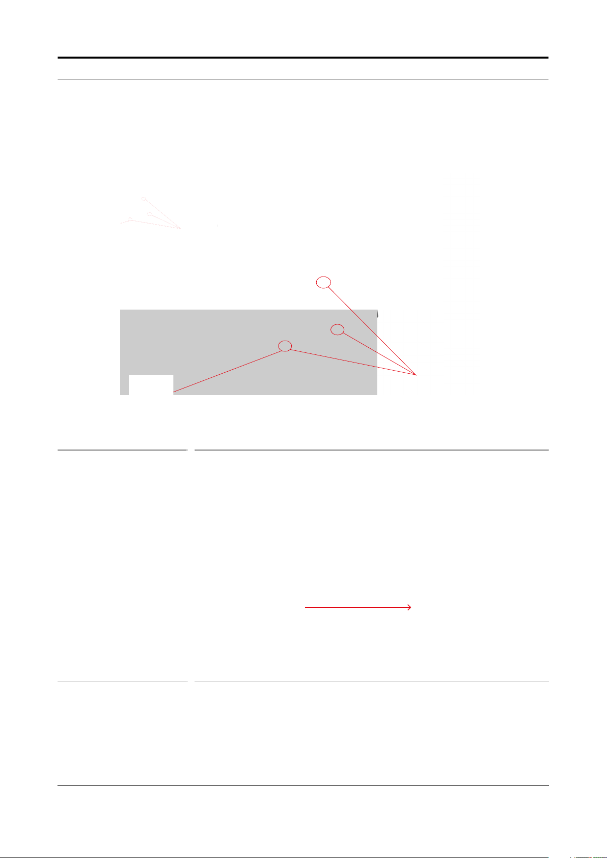
2.2.6.1 Grounding
WARNING! Make sure that the housing of the MSC-L is properly
bounded to the Protective Earth (PE). See FIGURE
2-1 for external grounding of the MSC-L and FIGURE
2-2 for bonding any AC mains wire.
Fusion4 MSC-L Part No.: 4418309_Rev11
2- 4 Installation & Operation Manual
Page 27
Safety - Safety Instructions for the MSC-L
3
g
8 point grounding
Also, make sure that the electrical resistance of the
ground connections is below the maximum limit/
value prescribed by national, local, and company
requirements.
3 point grounding
point groundin
FIGURE 2-1 External grounding connections of the MSC-L
FIGURE 2-2 Internal grounding connections of the MSC-L
3 point grounding
F4 A10 -00 02
WARNING! Maintaining the ground bonding of the lid to the local
Protective Earth (PE) using the lid ground wire is
crucial for ensuring intrinsic safety.
Part No.: 4418309_Rev11 Fusion4 MSC-L
Installation & Operation Manual 2 - 5
Page 28
Safety - Safety Instructions for the MSC-L
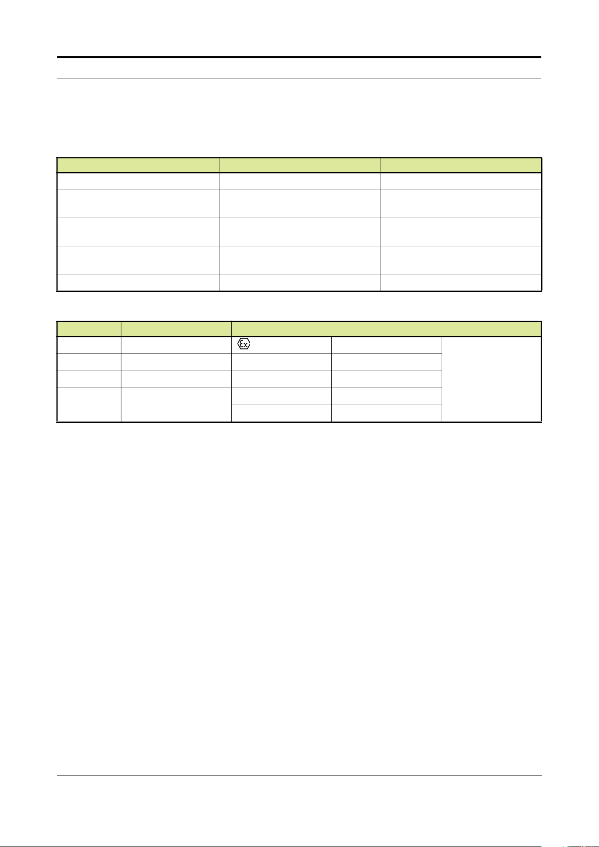
2.2.7 Accordance to Regulations
2.2.7.1 Explosion Safety Limiting Values
Explosion safety items Limiting values Type of protection
Power supply (Mains input): 100 - 240 VAC, 50 - 60 Hz
Maximum allowed power dissipation
inside the enclosure:
LAD interface circuit (LAD front connector):
Thermal protection, limitation of the
output current
U
m
2.2.7.2 Explosion Safety
90 W
Uo = 15.75 V, Io = 1.49 A, Po = 1.92
W, Co = 2.69 μF; Lo = 62 μH
160 mA
250 V
AC
Type of protection intrinsic safety Ex
ia IIB
Approval Certificate no. Type of protection identification
ATEX DEKRA 12ATEX0101 X II 2 G Ex d [ia] IIB T6 Gb
IECEx DEK 12.0021 X Zone 1 Ex d [ia] IIB T6 Gb
FM 3048063 Class I, Division 1 group C, D T4
CSA 2673172
2.2.7.3 Low-Voltage Directive
Class I, Division 1 Group C & D T6
Class I, Zone 1 Ex d [ia] IIB T6 Gb
The MSC-L is suitable for the following categories.
Pollution degree 2
Overvoltage category II
Class I equipment
= -40 °C ... +65 °C
T
a
(-40 °F ... +149 °F)
Fusion4 MSC-L Part No.: 4418309_Rev11
2- 6 Installation & Operation Manual
Page 29

Safety - Safety Instructions for the MSC-L
2.2.7.4 The MSC-L Labels
NOTE: Type plates are exemplary and subject to change.
FIGURE 2-3 Identification labels with the safety note on the MSC-L
Part No.: 4418309_Rev11 Fusion4 MSC-L
Installation & Operation Manual 2 - 7
Page 30

Safety - Safety Instructions for the LAD
FIGURE 2-4 W&M approvals type plate for Fusion4 MSC
2.3 Safety Instructions for the LAD
FIGURE 2-5 Local Access Device LAD
WARNING! You must strictly follow all the safety instructions
mentioned in this manual and the safety instructions
shipped with the MSC-L during installation, commissioning, operation, and maintenance for the safe
operation of the device.
Fusion4 MSC-L Part No.: 4418309_Rev11
2- 8 Installation & Operation Manual
Page 31

Safety - Safety Instructions for the LAD
The LAD may be used in hazardous areas as follows:
USA (FM) and Canada (CSA) Canada (CSA)
Safety
level
Class 1,
Division 1
Class 1,
Division 2
Safe
Area
Remarks
WARNING!
Substitution of
components
may impair
intrinsic safety.
WARNING!
Substitution of
components
may impair
intrinsic safety.
- Safe
Safety
Level
Class 1,
Division 1
resp.
Zone 1
Class 1,
Division 2
resp.
Zone 2
Zone
Remarks
- Safe
WARNING!
Substitution of
components
may impair
intrinsic
safety.
WARNING!
Substitution of
components
may impair
intrinsic
safety.
Rest of the World (ATEX /
IECEx)
Safety
level
Zone 1 -
Zone 2 -
Zone
Remarks
-
Part No.: 4418309_Rev11 Fusion4 MSC-L
Installation & Operation Manual 2 - 9
Page 32

Safety - Safety Instructions for the LAD
2.3.1 General
The LAD is a hand-held controller used for interfacing with the MSC-L.
WARNING! Only use the instrument for its intended purpose.
2.3.1.1 EC declaration of conformity (for EU)
Refer to the EC declaration of conformity and ATEX certificate(s),
shipped with the device for EC declarations.
2.3.1.2 Control Drawings for FM & CSA
Refer to the control drawings shipped with the MSC-L for FM and CSA.
2.3.2 Explosion Safety
Approval Certificate no. Type of protection identification
ATEX KEMA 10ATEX0152 II 2 G
Ex ia IIB T4 Gb
IECEx IECEx KEM 10.0070 Zone 1
FM 3041202 Class I, Division 1 group C, D T4
Class I, Division 1 group C, D T4
CSA 11.2395571
Zone 1 Ex ia IIB T4
T
= -20 °C ... +65 °C
a
(-4 °F ... +149 °F)
WARNING! This is an intrinsically safe device and may only be
connected to devices with compatible intrinsically
safe parameters, such as the MSC-L.
Connection of non-intrinsically safe signals invalidates the approval. The electrical data of the intrinsically safe circuits is to be taken from the certificate.
2.3.3 Commissioning
The LAD and the Fusion4 parent devices must be commissioned using
this controller trained by Honeywell Enraf. The service technician must
have knowledge of the national, local and company requirements for
electrical equipment in hazardous areas.
2.3.4 Operation
After connecting to the MSC-L, the LAD can be used for its intended
purpose.
2.3.5 Maintenance and Troubleshooting
The LAD hardware is non-servicable, in case of damage contact
Honeywell Enraf for replacement.
Fusion4 MSC-L Part No.: 4418309_Rev11
2- 10 Installation & Operation Manual
Page 33

Safety - Safety Instructions for the LAD
2.3.6 Additional Information
For additional information about Honeywell Enraf’s solutions, see the
back cover of this manual to contact Honeywell Enraf or its
representative.
2.3.7 Environmental Conditions
The environmental conditions regarding the allowable operating
temperature is -20 °C to +65 °C (-4 °F to +149 °F), relative humidity is
RH 5 to 95%, non-condensing, and operating pressure is atmospheric.
Part No.: 4418309_Rev11 Fusion4 MSC-L
Installation & Operation Manual 2 - 11
Page 34

Safety - Safety Instructions for the LAD
2.3.8 The LAD Labels
FIGURE 2-6 Identification labels with safety note on the LAD
Fusion4 MSC-L Part No.: 4418309_Rev11
2- 12 Installation & Operation Manual
Page 35

Safety - Safety Instructions for the IR Controller
2.4 Safety Instructions for the IR Controller
FIGURE 2-7 The IR Controller
WARNING! You must strictly follow all the safety instructions
mentioned in this manual and the safety instructions
shipped with the MSC-L during installation, commissioning, operation, and maintenance for the safe
operation of the device.
The IR Controller may be located in explosion safety areas as follows:
USA (FM) and Canada (CSA) Canada (CSA)
Safety
level
Class 1,
Division 1
Remarks
WARNING!
Do not open
battery
compartment
in a hazardous
area. Use only
approved
batteries, see
label.
Safety
Level
Class 1,
Division 1
Remarks
WARNING!
Do not open
battery
compartment
in a
hazardous
area. Use only
approved
batteries, see
label.
Rest of the World (ATEX /
IECEx)
Safety
level
Zone 1 WARNING!
Remarks
Do not open
battery
compartment
in a hazardous
area. Use only
approved
batteries, see
label.
Part No.: 4418309_Rev11 Fusion4 MSC-L
Installation & Operation Manual 2 - 13
Page 36

Safety - Safety Instructions for the IR Controller
USA (FM) and Canada (CSA) Canada (CSA)
Safety
level
Class 1,
Division 2
Safe
Area
Remarks
WARNING!
Do not open
battery
compartment
in a hazardous
area. Use only
approved
batteries, see
label.
- Safe
Safety
Level
Class 1,
Division 2
Zone
Remarks
- Safe
2.4.1 General
The Fusion4 IR Controller is a hand-held remote controller, which is an
infrared-type control device. The device facilitates programming the
Enraf Fluid Technology IR Controlled Equipment remotely.
The device contains all the necessary program codes installed. Hence,
the user programming is not required.
WARNING!
Do not open
battery
compartment
in a
hazardous
area. Use only
approved
batteries, see
label.
Rest of the World (ATEX /
IECEx)
Safety
level
Zone 2 WARNING!
Zone
Remarks
Do not open
battery
compartment
in a hazardous
area. Use only
approved
batteries, see
label.
-
2.4.2 Precautions
Clean the device with a damp cloth.
Use additional protection in areas where damage may occur.
Do not repair the device without permission to avoid the invalidation
of the certificate.
Do not leave the device in direct sunlight or place it near a heat
source.
Handle the device gently. Do not drop the device or subject it to other
types of stress.
Do not touch any solvent or aggressive substances before touching
the enclosure as it is made of plastic.
Store the device at room temperature in a clean and dry location.
To avoid damage to the device or shortening of battery life, use the
correct type of batteries.
To prevent battery usage when storing the device in an unused
condition for a long time, make sure that the buttons are not pressed.
To prevent damage caused by leaking batteries, remove the
batteries before storing the device in an unused condition for a long
time.
Fusion4 MSC-L Part No.: 4418309_Rev11
2- 14 Installation & Operation Manual
Page 37

Safety - Safety Instructions for the IR Controller
2.4.2.1 EC declaration of conformity (for EU)
Refer to the EC declaration of conformity and ATEX certificate(s),
shipped with the device for EC declarations.
2.4.3 Installation
Perform the following steps to install the device.
1. Remove the security screws from the compartment lid.
2. Slide the battery compartment lid from the device.
3. Install the 3 AAA Alkaline batteries ensuring that the plus (+) and the
minus (-) polarity of the batteries are correct.
NOTE: Removing the batteries does not remove the Fusion4
IR Controller memory.
Always replace the batteries with new ones.
Use only batteries approved for use.
WARNING! Do not open the battery compartment or change the
batteries in a hazardous area.
2.4.4 Commissioning
The IR Controller and the Fusion4 parent devices must be
commissioned using this controller by qualified service technician,
trained by Honeywell Enraf. The service technician must have
knowledge of the national, local, and company requirements. for
electrical equipment in hazardous areas.
2.4.5 Operation
After connecting to a Fusion4 parent device (for example, the MSC-L),
the Fusion4 IR Controller can be used for its intended purpose.
Perform the following steps to use the device.
1. Direct the device at the IR port of the equipment to be programmed.
2. Select ATTN on the IR Controller to turn the device and provide the
initial program command to the MSC-L.
REMARK: Refer to the specific equipment’s user’s manual for
defined programmed functions.
The device automatically stops after 30 seconds if an
activity is not performed. This helps in preserving the
battery life.
2.4.6 Maintenance and Troubleshooting
In the unlikely event of a malfunction, only a qualified service technician,
trained by Honeywell Enraf, and with the knowledge of safety
regulations for working in hazardous areas, must be allowed to repair
the MSC-L.
Part No.: 4418309_Rev11 Fusion4 MSC-L
Installation & Operation Manual 2 - 15
Page 38

Safety - Safety Instructions for the IR Controller
2.4.7 Additional Information
For additional information about Honeywell Enraf’s solutions, see the
back cover of this manual to contact Honeywell Enraf or its
representative.
2.4.8 IR Controller Labels
Fusion4 MSC-L Part No.: 4418309_Rev11
2- 16 Installation & Operation Manual
Page 39

Safety - Liability
FIGURE 2-8 Identification labels with Safety note on the Fusion4 IR Controller
2.5 Liability
The information in this installation manual is the copyright property of
Honeywell International Inc. Honeywell International Inc. disclaims any
responsibility for personal injury or damage to the equipment caused by
the following:
Deviation from any of the prescribed procedures.
Execution of activities that are not prescribed.
Neglecting the safety regulations for handling tools and use of
electricity.
The contents, descriptions, and specifications in this manual are subject
to change without notice. Honeywell International Inc. accepts no
responsibility for any errors that may appear in this manual.
WARNING! Only certified technicians are authorized to make
changes to the MSC-L configuration. All modifications must be in accordance with the guidelines as
set forth by Honeywell International Inc. Modifications not authorized by Honeywell International
Inc. invalidates the approval certificates.
Part No.: 4418309_Rev11 Fusion4 MSC-L
Installation & Operation Manual 2 - 17
Page 40

Safety - Liability
This page is intentionally left blank.
Fusion4 MSC-L Part No.: 4418309_Rev11
2- 18 Installation & Operation Manual
Page 41

System Description - Introduction
CHAPTER 3 SYSTEM DESCRIPTION
3.1 Introduction
3.1.1 General
The main function of the MSC-L is to assist in loading the liquid
products from a storage area to another containment vessel. That is,
the MSC-L helps the smooth movement and accurate measurement of
the liquid product being transferred. The MSC-L is also capable of
creating a new composite product during the transfer operation by
combining one or more different products together to form a new
product. The MSC-L creates the final, required product based on a
user-supplied specification, known as a Recipe.
For more information about Recipes, refer to the section CHAPTER 5 -
Operation.
The types of composite products that the MSC-L can create is limited by
various physical constraints such as product piping, isolation valves, the
availability of pumps, and blend valves.
The MSC-L can create composite products by combining products
through one of the following methods.
Blending - The process of combining two or more products contin-
uously.
Additive injection - The process of injecting small and discrete
amounts of a product (an additive) into another product.
3.1.1.1 Transactions and Batches
The MSC-L uses the following terms to control and record the product
transfer process.
Transaction - A single user session during which one or more
batches may be initiated. A transaction also defines the basic unit of
financial reconciliation.
Batch - Loading of a preset amount of final product into a
compartment on the vehicle.
3.1.2 Batch principle
Batch is defined as the loading of a preset amount of the final product
into a compartment on the vehicle. This final product may be a single
product or a blended product made on-the-fly by the MSC-L. If more
than one compartment is available, then more than one batch per
transaction can be initiated. There are no dependencies between
batches. That is, each compartment has its own independent operation.
If there are more than one load arm associated with the MSC-L then
multiple batches may be running simultaneously in the MSC-L.
Part No.: 4418309_Rev11 Fusion4 MSC-L
Installation & Operation Manual 3 - 1
Page 42

System Description - Introduction
3.1.2.1 Batch Flow Stages
Following are the four batch flow stages for the MSC-L.
Initial Flow Phase
In the initial state, product is initially slowly added to the receiving
container to mitigate the risk of electro-static buildup within the
container. The loader will continue to deliver product at the Initial
Flow Rate until the Deliver Product Volume reaches the Initial
Volume.
Full Flow Phase
In the Full Flow Phase, the product is delivered quickly so that the
batch can finish as soon as possible. The Full Flow Phase continues
until the Delivered Product Volume reaches the value equal to (Batch
Preset Volume – Pre-Stop Volume).
Pre-Stop Phase
In the pre-stop phase the flow rate is decreased so that the flow can
be stopped quickly and accurately at the very end of the load. The
Pre-stop phase continues until the Delivered Product Volume
reaches the value equal to (Batch Preset Volume – Valve closing
quantity).
Clean Arm Volume
The last part of a batch typically is to “clean arm”, it is essential that
all blend volumes are delivered before that time. To achieve this, a
certain percentage of headroom is included in the blend flows such
that effectively enlarge the clean arm volume in an ideal case.
Headroom is the transition quantity during flow rate change from high
flow state to pre-stop flow state. This solution is because a larger
clean arm volume is permitted while the opposite is not true.
Always recommended to use clean arm volume to maintain correct
blend ratio in the compartment. For no clean arm functionality, blend
percentage may not be accurate due to few unknown blend percentage
already available in arm which was delivered in the previous batch.
Blending is allowed in any stage as long as the flow rates of the streams
do not fall below the minimum measurement boundary. The Clean Arm
Volume is calculated back from the end of the batch. This means that,
when configured, the clean arm volume can be loaded over multiple
phases in the flow profile. Blending is not allowed when the clean arm
volume has to be delivered. The is to assure that at the end of the batch
the blend ratio is within specifications and the clean arm volume is not
compromised.
It is possible to specify a clean arm volume greater than the pre stop
volume. This implies that part of the clean arm volume can be delivered
during full flow. Given the fact that no blending is allowed during delivery
of the clean arm volume it is possible that the flow rate of the main
stream can be increased while still adhering the before mentioned
restrictions.
Fusion4 MSC-L Part No.: 4418309_Rev11
3- 2 Installation & Operation Manual
Page 43

System Description - Introduction
The flow rate setpoint calculated such that they meet stream and arm
limitations. For the arm this means that the total flow rate may never
exceed the arm’s full flow rate. For streams, it means that the flow rate
must always be in the inner window of its valve and meter minimum and
maximum flow rates in the steady state.
The following image illustrates how the actual batch blend percentage
may vary during the load based on the various configuration settings.
For instance, if the initial flow rate is too small for accurate blend
product measurement, then blending only starts in the Full Flow Phase.
Secondly, if the clean arm functionality is configured, then the MSC-L
intentionally over blends to ensure that all the required blend products
are dispensed before the clean arm phase begins.
NOTE: To adequately match various specific applications,
the MSC-L has a number of configurable
parameters. For an explanation of all these
parameters and their specific settings, see chapter 5
"Operation".
Part No.: 4418309_Rev11 Fusion4 MSC-L
Installation & Operation Manual 3 - 3
Page 44

System Description - Introduction
3.1.3 Types of Blending
The following sections describe the various types of blending supported
in the MSC-L.
3.1.3.1 Straight Loading
Straight loading is a batch in which only the main product is dispensed
without any additional blend products.
FIGURE 3-1 Straight Arm Loading
3.1.3.2 Ratio Blending
Ratio blending is a process in which the main product is blended with
one or more blend products, when a batch is loaded. The amount of
each product is defined by the recipe selected for the batch. Each
product - main and blend(s) - must be controlled independently by its
own product valve and must have its own meter.
FIGURE 3-2 Ratio Blending Piping
3.1.3.3 Side Stream Blending
Side Stream blending is a batch blending where one blend product is
blended into the main product. The blend product must have its own
valve and meter. The combined, final, blended product must also have
its own valve and meter.
Fusion4 MSC-L Part No.: 4418309_Rev11
3- 4 Installation & Operation Manual
Page 45

System Description - Introduction
In side stream blending, the main product does not have its own valve
and meter. The flow rates of both the main and blend products are
therefore a function of both valves.
FIGURE 3-3 Side Stream Blending Piping
3.1.3.4 Sequential Blending
Sequential blending is a process in which multiple products share a
single flow meter and control valve and are loaded one by one in
sequence. Each product has dedicated pump demand and block
valves. The mixing of the products takes place in the receiving
compartment. The amount of each product and order of loading is
defined by the recipe selected for the batch. See chapter 5 "Operation"
for more details.
FIGURE 3-4 Sequential Blending Piping
Part No.: 4418309_Rev11 Fusion4 MSC-L
Installation & Operation Manual 3 - 5
Page 46

System Description - Introduction
3.1.4 Additive Injection
Additive injection is a process in which small amounts of additives are
added to the final product. The additive product is injected in pace with
the product flow. That is, the additive injection occurs after an interval of
configured pacing volume until the end of the batch. The recipe
configured on the MSC-L controls the rate of additive being injected into
the product stream.
When the MSC-L determines that an additive cycle is required, it opens
the solenoid control valve and injects a small quantity of additive into
the product stream. When the amount of additive is reached for that
cycle, the solenoid valve is closed and the instrument waits until the
next additive cycle is required. The additive injection cycle repeats in
this manner, which keeps the additive synchronised with the product
flow.
MSC-L also supports additive injection by interfacing with External
additive controller. For more details, see chapter 5.13 "Interfacing With
External Additive Controller".
NOTE: The MSC-L assumes that the additive piping is done
in such a way that additives comes in upstream
(before) the custody transfer flow meter.
When the additive piping is done in such a way that
additives comes in downstream (after) the custody
transfer flow meter the additive is not a part of the
finalized product volume but the individual additive
volumes are measured and are part of the transaction record and therefore available when viewing
transactions or for printing additive reports by the
Fusion4 Portal.
3.1.5 Loading Principle
The loading arm of the MSC-L supports the control of the following as
described in the following figure.
Maximum 7 product streams
Maximum 12 additive streams (inclusive of internal additive streams
and upto 6 external additive streams)
Fusion4 MSC-L Part No.: 4418309_Rev11
3- 6 Installation & Operation Manual
Page 47

System Description - Introduction
utillizes
utillizes
However, a single batch (load to a compartment) can only control a
subset of the product streams or the additive streams.
For each batch, the MSC-L supports the control of the following, as
described in the following figure.
Stream with main product
Maximum 3 blend streams
Maximum 6 additive streams (inclusive of internal and external
additives)
This sub set is defined by the recipes running on that arm.
Part No.: 4418309_Rev11 Fusion4 MSC-L
Installation & Operation Manual 3 - 7
Page 48

System Description - Introduction
3.1.5.1 Device loading capabilities
Following are the device loading capabilities, as described in the
following figure.
Maximum of 6 simultaneous loading arms are supported.
Maximum of 50 recipes can be configured per loading arm.
Maximum of 10,000 transactions First in First Out (FIFO) can be
stored in the device.
A transaction (record of product transfer to one customer) can be
transferred to the Fusion4 Portal (transaction record) for W&M
compliant BoL storage and printing.
A transaction can contain batches loaded with maximum of 6
different loading arms.
A transaction contains maximum of 20 batches.
A batch simultaneous controls a maximum of 10 streams:
• Stream with main product
• Up to 3 blend streams
• Up to 6 additive streams
Fusion4 MSC-L Part No.: 4418309_Rev11
3- 8 Installation & Operation Manual
Page 49

System Description - MID Compliance
3.1.6 Menu-based MSC-L Control
By using service tools (the LAD, the IR controller, and the integrated
keyboard) the MSC-L can be controlled through its integrated and menu
based interface.
This control device can be one of the following three devices.
The RS-485 connection (through an Ex d/ Ex i connector on the front
of the MSC-L) based on the LAD.
The Fusion4 IR Controller.
Integrated keyboard.
Using one of these devices, it is possible to navigate the menu items,
change the settings (commissioning), initiate a calibration, and
diagnose problems.
3.2 MID Compliance
3.2.1 Introduction
The Measuring Instruments Directive (MID) (2004/22/EC) is
designed to provide a level playing field in Europe, for custody transfer
measuring equipment and systems. The MID currently covers 10
instrument categories, for uniform legislation in the 27 EU countries.
The implementation of this directive in national legislation became due
on the 30th of October 2006.
The MSC-L is 100% MID-compliant.
This legislation results in breaking down trade barriers and improving
competition, which is one of the main objectives of the European Union.
In the directive, the specific articles on each of the instrument
categories are called Annexes. The Annex relevant to the measurement
of petroleum products is “flow metering of liquids other than water”
and is identified as Annex MI-005. The requirements in this Annex are
based on the OIML recommendation R117-1, which is the pre-eminent
set of guidelines for Weight & Measures of petroleum metering
installations, for a considerable time.
3.2.2 MID Approval Approach
One of the key changes in the Measurement Instruments Directive (MI-
005) compared to previous national legislation, is that the total metering
system is now subject to perform in the accuracy specification, and not
just specific components. This means that not only the flow meter is
subject to certification but also others.
Part No.: 4418309_Rev11 Fusion4 MSC-L
Installation & Operation Manual 3 - 9
Page 50

System Description - MID Compliance
Essential parts of the metering system, such as temperature
transmitters, electronic volume converters air-eliminators, and so on. In
addition to this, the method with which the system is built is also
examined by the Notified body. In turn the Notified Bodies are
scrutinized by the European Board of Accreditation.
The system approval process for MID consists of two main steps:
‘Bringing on the market’ - type-examination by a Notified body in
accordance with Annex-B of the MID. This generates a so-called
type-examination certificate.
‘Putting it into use’ - conformity check of the essential parts and a wet
calibration in the legal specification. This is implemented in
accordance with Annex F or D of the MID. This generates the system
approval.
The system can now be used for trade and excise applications. The
received approval is subject to recalibration at 1 or 2 year interval, and
this is determined on national level.
NOTE: Evaluation Certificate provides demonstration that
the MSC-L as a component of an MID-compliant
instrument is approved per MID and OIML
requirements.
3.2.3 Component-level Requirements
For blending applications such as ethanol- and biodiesel-blending, the
minimum required accuracy of the metering line is ±0.5% (class 0.5).
The flow metering element of the system is allowed ± 0.3% in accuracy,
and the remainder of the system is permitted to show maximum errors
to ± 0.2%.
As the errors are directly related to inaccuracies, they are added to get
the total maximum. Therefore, ± 0.5% is the maximum allowed
discrepancy between what the seller states as the volume transferred,
and the actual volume the buyer receives.
Fusion4 MSC-L Part No.: 4418309_Rev11
3- 10 Installation & Operation Manual
Page 51

System Description - MID Compliance
FIGURE 3-5 Component-level requirements (flow accuracy)
In the metering line, the essential parts of the system are the flow meter,
the temperature sensor, and the load controller itself. The flow meter
physically measures the flow and generates pulses, which are related to
the volume passed through the meter. For reliability, the pulses are dual
phase shifted and are constantly checked by the electronic load
controller for integrity, according to API and ISO. Through the
temperature sensor (transmitter) the metered volume can be corrected
to base temperature of either 15°C (60°F) or 20°C (68°F), in
accordance with the ASTM standards. If a temperature transmitter is
applied, then component level requirements must also have an
evaluation certificate. For the temperature sensor (Pt100) it is not
required.
Part No.: 4418309_Rev11 Fusion4 MSC-L
Installation & Operation Manual 3 - 11
Page 52

System Description - MID Compliance
FIGURE 3-6 Component-level requirements (Temperature and Pressure accuracy)
The load controller evaluation is quite complex, but in principle it has to
comply with the security of signal and data handling, as required by MID
and working documents of WELMEC.
A very stringent requirement is the EMC standard for industrial use of
electronic equipment. Electro-magnetic noise might influence the
measurement of the metering signal, and this is not allowed to occur
outside the maximum given accuracy.
Fusion4 MSC-L Part No.: 4418309_Rev11
3- 12 Installation & Operation Manual
Page 53

System Description - MID Compliance
3.2.4 System-level Requirements
With any new equipment legislation such as MID, there is a raft of new
issues and criteria that need to be understood by both those who are
manufacturing the equipment and those who seek to utilise it. In the
downstream oil and gas sector the volume of that legislation is vast. In
the case of MID where the legislation crosses the boundaries of
mechanical and electronic hardware, software, communications, and
reconciliation and reproduction of data, correctly understanding the
legislation, can be particularly vexing.
For this reason, the provision of “system solutions” is seen by many as
the most efficient method of procuring equipment that is in compliance
with their regulatory needs. Instead of having to understand the
individual technical requisites of each individual component of a system,
they only need to understand their “end game”. “I need an MID
compliant ethanol blending system” is far easier to define than
specifying the individual technical specifications of each component of
that system. For this to work though, the acquirer has to have
confidence that the supplier is suitably knowledgeable to accurately
provide them with the correct solution for their needs. The provision of a
“solution” circumnavigates the minefields associated with integrating
multiple components into compliant system arrangement.
Pre-configured biofuel blending systems such as the MSC-L do exactly
this. Piecing together accurately specified MID-compliant components
to provide an end-to-end solution. Combining the physical measuring
element with the electronic control device and associated reconciliation
options such as digital storage or printing of BoLs. Each of these
functions is required to operate under the concise guidelines laid out
under MID and associated legislation such as OIML R117 and
WELMEC.
3.2.5 The Fusion4 MSC-L
The heart of the system is the Fusion4 MSC-L.
Founded on Honeywell Enraf’s proprietary FlexConn™ architecture, the
MSC-L is part of the Fusion4 portfolio of loading automation and control
products family. A modular collection of mechanical, electronic, and
software sub-systems that can be integrated with each other to create
scalable solutions.
The FlexConn™ approach has enabled Honeywell to take the wellproven functionality of its additive and blending portfolio and bring all
the options together as a single offering, which is configurable to suit
the end you need. Subsequently, the MSC-L incorporates 12 separate
devices, each providing individual functionality, and each one
configurable from one single device, and selectable through a license
key.
Part No.: 4418309_Rev11 Fusion4 MSC-L
Installation & Operation Manual 3 - 13
Page 54

System Description - System Architecture
The MSC-Ls solution approach facilitates the ratification of both the MID
compliance steps mentioned previously, ‘bringing on the market’ and
‘putting into use’, by pre-configuring all components in accordance with
the MID requirements, and checking conformity through pre-installation
testing before delivery, as a complete system. This method not only
reduces the risk of non-compliance, but also speeds up the MID
qualification process for the system owner.
For the owner, ‘putting into use’ qualification not only includes the
accuracy and security of the physical operation of the blend process,
but also the reconciliation and reproduction of the measurement data.
This is applicable, whether the information is to be stored locally on the
device, distributed and stored on peripheral devices, or reconciled as a
Bill of Lading print-out. For the system to be fully compliant, any of these
functions must also operate in the MID criteria.
As such, the MSC-L offers a number of options to ensure compliance.
Firstly it implements a large transaction storage memory of 10,000
transactions, which allows a device to operate for over three months
without losing a single transaction, in standard operating conditions.
Alternatively, the MSC-L can have its transaction data securely
downloaded through the Fusion4 LAD (Local Access Device). This
allows the MSC-L to have its memory cleared in preparation for the
storage of another 10,000 transactions. The transactions subsequently
transferred to the LAD can then be manually transferred to any
peripheral system for storage or printing through the SD card.
Finally the preferred method is to link the MSC-L through Comms to the
Fusion4 Portal software package. When connected, all the transaction
data are scanned and collected by Portal from each device. The
transaction record is stored and can be printed directly or distributed
through OPC to third party systems for separate reconciliation.
The Fusion4 Portal BoL Print facility is fully MID compliant, and
therefore can facilitate a stand-alone blending infrastructure that meets
all the MID requirements. Along with the MID print functionality and the
OPC capability, built-in modules for the Portal software suite also
include remote configuration, remote event monitoring and alarm
handling and advanced LAD interaction tools.
3.3 System Architecture
The MSC-L is installed as per the Honeywell Enraf’s proprietary
FlexConn architecture. The MSC-L is a member of Fusion4 portfolio of
Loading Automation and Control products.
The MSC-L system is built up of interchangeable hardware modules.
These modules consist of uniform Printed Circuit Boards (PCBs), each
of them representing a different and a unique functionality. See section
3.6.1 - PCB Details, for more information.
Fusion4 MSC-L Part No.: 4418309_Rev11
3- 14 Installation & Operation Manual
Page 55

System Description - System Architecture
C
A
N
-
b
u
s
Fusion4Fusion4
MSC-LMSC-L
CAN-PSF-MSC
RS-485/ETHERNET
(REDUNDANT)
RS-485
ETHERNET
RS-485
TAS/FUSION4
PORTAL
MSC-L DISPLAY
W&M SWITCH
IDENTIFICATION
SYSTEM - RS-485
IR
FUSION4 IR CONTROLLER
ESD
STRAINER
DEAD MAN
DI
PO
DO
DI
REMOTE TOTALIZER
OVERFILL
DO
EMR
AO
CONTROL VALVE
AO
AI
PLC/DCS
DI
DO
DI
DI
DI
DO
DO
TANK LOW LEVEL/EMPTY
VAPOUR RECOVERY
GROUNDING
DO
DI
BLOCK VALVE
RIT panel
BAY BARRIER
BAY LIGHT
LOAD ARM
2*DO
PUMP
MONOBLOCK
SOLENOID
VALVE
DO
S-PI
D-PI
RS-485
TEMPERATURE
PT100
RTD
AI
PRESSURE
MAIN STREAM
U40
K11
K13
K12
K14
ON
U39
123456
U34
U35
U36
U41
U43
U42
CN1 CN2
LE1 LE2 LE3
K3K6K7
K1K4K9
K10
K2K5K8
U49
U32
U22
U21
U20
U25
U24
U23
U26
U27
U28
U29
U30
U31
U33
U38
TZ1
S1
D26
D30
L3
FM-IN-OUT
CAN-HMI-MSC
ON
123456
+
ON
1234
JP8
JP9
C11
C12
C1
SW1
U6
C10
U28
U26
U18
U21
JP10
JP7
CN2
CN4
U11
U8
U19
U10
U9
CN3
LE1LE2 LE3LE4LE5 LE6
CN7
SW2
CN9
CN8
CN5
CN6
FM-HMI
MAINS
SUPPLY
CAN-ARM-MSC
U40
K11
K13
K12
K14
ON
U39
123456
U34
U35
U36
U41
U43
U42
CN1 CN2
LE1 LE2 LE3
K3K6K7
K1K4K9
K10
K2K5K8
U49
U32
U22
U21
U20
U25
U24
U23
U26
U27
U28
U29
U30
U31
U33
U38
TZ1
S1
D26
D30
L3
FM-ARM
MSC-L KEYBOARD
AI
AI
DENSITY
SSC-A
FLOWMETER
FLOWMETER
FLOWMETERADDITIVE
INJECTION
BLEND
STREAM
DCV
QPI
QPI
2*DO
2*DO
DCV
CAN-IN-OUT-MSC
DI
LAD
With the software implemented on these hardware parts, each PCB
makes up a FlexConn module. These modules communicate with each
other through the serial CAN-bus. See FIGURE 3-7, for more
information.
FIGURE 3-7 The Fusion4 MSC-L architecture overview
Part No.: 4418309_Rev11 Fusion4 MSC-L
Installation & Operation Manual 3 - 15
F4 A10 -00 04
Page 56

System Description - FlexConn Modules
CAN-HMI-MSC CAN-IN-OUT-MSC CAN -ARM-MSC
CAN-L
CAN-H
3.4 FlexConn Modules
3.4.1 General
One of the main characteristics of the FlexConn architecture is the
placement flexibility of the FlexConn modules. The backbone of this
concept is the serial Control Area Network (CAN) bus to which each
FlexConn module connects.
= terminating resistor
FIGURE 3-8 FlexConn CAN bus concept
Each FlexConn module has one or more specific functions as follows:
A sensor function - Measures or calculates a process value, or
obtains a process value from a connected external instrument.
An application function - Controls the high-level operation of a
device. For example, stream control, flow control, or device control.
An Input/Output (I/O) function - Controls digital output or reads digital
input from instruments around the loading framework.
A communication function - Ensures the communication with a
communication interface unit or with a DCS, SCADA, tank inventory,
or another terminal automation system.
A display function - Ensures communication with the module(s)
through an HMI.
3- 16 Installation & Operation Manual
Fusion4 MSC-L Part No.: 4418309_Rev11
Page 57

System Description - Hardware Structure
3.5 Hardware Structure
For details on the hardware structure of the MSC-L, see the following
sections.
3.5.1 Housing
The housing of the MSC-L consists of an enclosure and a cosmetic
cover. The enclosure can be opened by removing the cosmetic cover
and loosening the 32 captured bolts. See FIGURE 3-8, for more
information.
NOTE: Turn the bolts two times on the cosmetic cover to
loosen the bolts and retain them in the lid.
FIGURE 3-9 The MSC-L enclosure
Part No.: 4418309_Rev11 Fusion4 MSC-L
Installation & Operation Manual 3 - 17
Page 58

System Description - Hardware Structure
FIGURE 3-10 Housing of the MSC-L
Label Description
A Cosmetic cover
B Captive socket-head screws (32x), of which one can have an enlarged
head for sealing purposes (see figure left)
C Lid
D O-ring (standard available part)
E Glass
F Glass retainer rings (not visible in the front view of the MSC-L)
G Keyboard
H W&M switch
Fusion4 MSC-L Part No.: 4418309_Rev11
3- 18 Installation & Operation Manual
Page 59

System Description - Hardware Structure
3.5.2 Interior
The boards are mounted on the connector slots provided on the
backplanes.
The CAN-HMI-MSC board is connected to the backplane using a
pair of Sub-D 15 cables. The MSC-SHORTCUT-BOARD, CAN-PSFMSC, CAN-ARM-MSC board, and CAN-IN-OUT-MSC boards are
mounted on the connector slots provided on the backplane boards.
The following boards can be placed in the MSC-L.
MSC-SHORTCUT-BOARD
ARM1-BACKPLANE-MSC
ARM2-BACKPLANE-MSC
EX-IO-HMI-MSC-L
CAN-PSF-MSC
CAN-HMI-MSC
CAN-ARM-MSC
CAN-IN-OUT-MSC
FIGURE 3-11 PCB configurations, MSC-SHORTCUT-BOARD, and the CAN-HMI-MSC
Part No.: 4418309_Rev11 Fusion4 MSC-L
Installation & Operation Manual 3 - 19
Page 60

System Description - Hardware Structure
PCB name Modulea name Description
CAN-HMI-MSC FM-HMI Controls the display and the LAD interface.
CAN-ARM-MSC FM-ARM Provides the I/O functions required for
loading, blending, and additive injection
processes.
FM-PI Provides the firmware to control the pulse
input signals from the connected flow
meters.
CAN-IN-OUT-MSC FM-IN-OUT Provides I/O functions, which are
necessary to control the enhanced loading
and additive injection processes.
CAN-PSF-MSC - Delivers the internal power for the MSC-L.
MSC-SHORTCUT-BOARDS - Protects the internal electronics so that the
high current can be withdrawn.
A PCB with software installed
3.5.3 Grounding Concept
The CAN-ARM-MSC board and the CAN-IN-OUT-MSC board contain
two grounding points, which are mechanically connected with the metal
housing using the metal spacers, as displayed in FIGURE 3-12. In
addition, these boards connect the GND cables, which are connected to
Fusion4 MSC-L Part No.: 4418309_Rev11
3- 20 Installation & Operation Manual
Page 61

System Description - Hardware Structure
the backplane through multiple pins of the DIN41612 F-type 48-pins
connector.
FIGURE 3-12 Mechanical grounding of CAN-ARM-MSC and CAN-IN-OUT-MSC boards
The CAN-HMI-MSC board, which is mounted on the lid of the MSC-L
enclosure, connects directly to the metal housing through the nine
mounting screws, as displayed in FIGURE 3-13.
Part No.: 4418309_Rev11 Fusion4 MSC-L
Installation & Operation Manual 3 - 21
Page 62

System Description - Hardware Structure
FIGURE 3-13 Mechanical grounding of CAN-HMI-MSC board
WARNING! For ensuring intrinsic safety of the MSC-L, the
grounding connection of the lid to the main box and
the box to the local grounding system is very crucial.
If the grounding cable is required to be detached,
make sure you reinstall the device before any
operation is performed.
1. Open and install the fasteners from the device using a proper tool.
2. Make sure the construction is similar to the original assembly after
the grounding cable is detached and all the parts are repositioned in
a similar way when reinstalling. Take special care of the orientation of
the cable rings and toothed rings for the grounding cable.
3. Check the wire in the box and the lid. Make sure it is not damaged
before reinstalling.
4. Reinstall the original cable assembly. Do not replace it with random
parts.
NOTE: Complete replacement of the lid should only be done
in the Honeywell Enraf factory and not at the site.
Fusion4 MSC-L Part No.: 4418309_Rev11
3- 22 Installation & Operation Manual
Page 63

System Description - Hardware Structure
The lid of the metal housing is connected to the MSC enclosure through
a separate GND signal transmitted through the GND cable, as
displayed in FIGURE 3-14.
FIGURE 3-14 Cable (GND cable) used for grounding the lid of the MSC enclosure
The Protected Earth (PE) ground connections for external cables are
connected to one of the nine M4 studs at the bottom, using the gland
entries, as displayed in FIGURE 3-15.
FIGURE 3-15 PE ground connections for external cables
Part No.: 4418309_Rev11 Fusion4 MSC-L
Installation & Operation Manual 3 - 23
Page 64

System Description - PCB Layout
3.6 PCB Layout
Each FlexConn PCB consists of generic electronic parts and specific
electronics part.
The generic electronic parts can be found on any FlexConn modules.
The specific electronics part represent an application specific function.
On the generic electronics part, the following parts are available.
Program memory - Contains the module specific software.
Microprocessor/controller - Executes the module specific software
stored in the program memory.
Non-volatile memory - Stores the commissioning parameters and the
diagnostics data when the power is turned off.
Jumpers - Establish specific hardware settings.
Health LED (blue) - Indicates the general health status of the
FlexConn module.
The following table specifies the health status and the flashing
pattern on the FlexConn module.
Health Status Flashing Pattern
Good
Uncertain
Bad
Function LEDs - Indicates the module specific activities such as the
data being transmitted or received.
Voltage monitors and temperature sensors - Used for internal diag-
nostics purposes.
Fusion4 MSC-L Part No.: 4418309_Rev11
3- 24 Installation & Operation Manual
Page 65

System Description - PCB Layout
3.6.1 PCB Details
3.6.1.1 CAN-HMI-MSC
3.6.1.1.1 Functions
The CAN-HMI-MSC board is used as the basic Human Machine
Interface (HMI) for the MSC-L. The board supports various
communication interfaces, Ex-i interfaces, and the display interface
control.
Following are the functions of the CAN-HMI-MSC board.
Function Description
Display interface control Displays a 8” WVGA color display in the MSC-L lid.
RTC with battery backup Is used for the date and time stamping of the transaction data.
External backup battery is connected to the RTC to retain the real-time
information, even when the main power of the MSC-L is turned off.
Transaction storage memory Is the external, non-volatile memory for storage of the transaction details.
Display image memory Stores video data and it is interfaced to the Field Programmable Gate
Array (FPGA).
Power failure memory management Is the non-volatile memory for storage of measured values as a protec-
tion against the power failure.
HHC IR interface Is the HHC IR interface for the Fusion4 IR Controller.
Ambient light sensor Is the device used for sensing the ambient light condition. It is sensitive
to visible light and has peak sensitivity at 570 nm.
RS-COM (2-wire or 4-wire) The RS-485 serial communication block is used by the FlexConn micro-
processor to communicate with external devices using an RS-485 compliant physical layer. It can be configured for a 2-wire half-duplex or a 4wire full-duplex RS-485 communication.
ETHERNET The Ethernet communication block is used for allowing the FlexConn
microprocessor to communicate with the external devices using an
Ethernet-compliant physical layer.
Part No.: 4418309_Rev11 Fusion4 MSC-L
Installation & Operation Manual 3 - 25
Page 66

System Description - PCB Layout
1
Display interface control
RTC
battery backup
Transaction
storage
memory
Display
image
memory
Power failure
memory
management
FlexConn generic
ext RAM
RTC
battery backup
HHC
IR interface
Ambient
light sensor
ETHER
(Ethernet
isolated)
COMMS
RS485 (4-wire
isolated)
COMMS
RS485 (2-wire
isolated)
1
2
ON
123456
+
ON
1234
JP8
JP9
C11
C12
C1
SW1
U6
C10
U28
U26
U18
U21
JP10
JP7
CN2
CN4
U11
U8
U19
U10
U9
CN3
LE1 LE2 LE3 LE4 LE5 LE6
CN7
SW2
CN9
CN8
CN5
CN6
FIGURE 3-16 CAN-HMI-MSC functions (top) and physical layout (bottom)
3- 26 Installation & Operation Manual
Fusion4 MSC-L Part No.: 4418309_Rev11
Page 67

System Description - PCB Layout
ON
123456
+
ON
1234
JP8
JP9
C11
C12
C1
SW1
U6
C10
U28
U26
U18
U21
JP10
JP7
CN2
CN4
U11
U8
U19
U10
U9
CN3
LE1 LE2 LE3 LE4 LE5 LE6
CN7
SW2
CN9
CN8
CN5
CN6
3.6.1.1.2 Component Locations
FIGURE 3-17 CAN-HMI-MSC component locations
Item
reference
JP7, JP8 FlexConn jumpers for RS-485 CH5 finishing setting.
JP9 FlexConn jumpers for RS-485 CH3 finishing setting.
JP10 FlexConn jumpers for RS-485 CH4 finishing setting.
CN1 Programming connector for U11 (ARM controller).
CN2 LAD or keyboard connections to EX-IO-HMI-MSC-L.
CN3 Programming connector for U6 (FPGA).
CN4 microSD connector.
CN5, CN6 Connectors for interfacing with the ARM1-BACKPLANE-MSC.
CN7, CN8 Connectors for interfacing with the Varitronix display.
CN9, CN10 Connectors for interfacing with the Hitachi / PV.
LE1 Health of the board.
LE2 Configurable.
LE3 Configurable.
LE4 Ethernet auto negotiation.
LE5 Ethernet speed indicator.
LE6 FPGA Health.
U8,U9,U10 SDRAM.
U6 FPGA.
U11 ARM controller.
U19 Flash memory.
U1 A holder for IR receiver.
V2 Ambient light sensor.
Part No.: 4418309_Rev11 Fusion4 MSC-L
Installation & Operation Manual 3 - 27
Description
Page 68

System Description - PCB Layout
SW1 - FlexConn jumper function switches
Reference Jumper name Function when set to ON
SW1-1 FlexConn JP1 W&M entities protection
SW1-2 FlexConn JP2 Password is read protected
SW1-3 FlexConn JP3 Nothing used
SW1-4 FlexConn JP4 Spare
SW1-5 FlexConn JP5 Spare
SW1-6 FlexConn JP6 CAN bus termination
SW2 - RS485 CH5 mode selection
Reference Setting Function Description
SW2-1 ON 2-wire
interface
SW2-2 ON
SW2-3 OFF
SW2-4 OFF
SW2-1 OFF 4-wire
interface
SW2-2 OFF
SW2-3 ON
SW2-4 ON
2-wire RS-485 communication
4-wire RS-485 communication
Jumper for RS-485 communication terminating setting
Jumper Position Description
JP7, JP8, JP9 and
JP10
JP7, JP8, JP9 and
JP10
(1-2) Closed RS-485 communication with 120 is
terminated.
(2-3) Closed RS-485 communication is NOT termi-
nated.
NOTE: When position (1-2) of jumper JP7 is closed, it will
connect a resistance of 120 between terminals 3 &
4 of COM PORT 5
When position (1-2) of jumper JP8 is closed, it will
connect a resistance of 120 between terminals 1 &
2 of COM PORT 5
Fusion4 MSC-L Part No.: 4418309_Rev11
3- 28 Installation & Operation Manual
Page 69

System Description - PCB Layout
3.6.1.2 CAN-ARM-MSC
3.6.1.2.1 Functions
The function of the CAN-ARM-MSC board is to provide the minimum I/O
functions required for loading and for enhanced additive injection
processes.
The CAN-ARM-MSC board supports both W&M and non-W&M additive
injection and blending processes.
Following are the functions of the CAN-ARM-MSC board.
Function Description
12 Pulse Input DC (Quad PI) circuit Converts pulse signals from external flow measuring devices into
numeric data that can be read by a FlexConn microprocessor.
7 Analog Input (AI 4-20 mA Active/Passive)
circuits
2 Pulse Output DC (PO DC) circuits Converts logic signals from the FlexConn microprocessor into isolated
12 Digital Output Solid State Relay AC (DO-
SSR AC) circuits
Analog Output (AO 4-20 mA Passive) circuit
2 COMMS circuits (2-wire) The RS-485 serial communication block, which can be configured as a
An ETHER circuit The Ethernet communication block allows the FlexConn microprocessor
3 Resistance Temperature Detector (RTD
3-wire or 4-wire) circuits
Converts analog signals received from a single external 4-20 mA transmitter into a signal that can be read by the FlexConn microprocessor.
switched DC signals.
Converts logic signals from the FlexConn microprocessor into isolated,
high voltage, switched AC signals.
Converts signals from the FlexConn microprocessor into scaled 4-20 mA
analog signals.
2-wire circuit, allows the MSC-L to communicate with external devices
through an RS-485 compliant connection.
to communicate with external devices through an Ethernet physical compliant
layer.
Converts the temperature data from a remotely connected PT100 RTD
into a resistance value that can be read by the FlexConn microcontroller
and then converted back into a temperature value.
Part No.: 4418309_Rev11 Fusion4 MSC-L
Installation & Operation Manual 3 - 29
Page 70

System Description - PCB Layout
Quad PI
FlexConn generic
ext RAM
AI
DO-SSR
(AC)
AO
COMMS
(2-wire
isolated)
7
12 2 3
21
(2-wire
act/pass)
(2-wire
passive)
1
12
PO
(DC)
RTD
3-wire or
4-wire
Ethernet
isolated
CN1 CN2
U66
L35
U47
U8
K5
K6
K7
K8
K9
K10
K11
K12
K4
K3
K2
K1
FIGURE 3-18 CAN-ARM-MSC functions (top) and physical layout (bottom)
U7
U50
U16
U14
U22
U6
U52
T3
X5
U55
U57
A1 A18
V1 V18
19
20
U17
1
2
U25
U30 U68
U48 U29
U56
U13 U12
U24
U72 U54
U53
U4
U46
ON
123456
U51
U9
U26
U27
U65
U63
U64
U71
U69
U5
U28
G1
U67
G2
U1
U9
U10
U11
Fusion4 MSC-L Part No.: 4418309_Rev11
3- 30 Installation & Operation Manual
Page 71

System Description - PCB Layout
U8
U4
U9
U47
U7
U50
U9
U1
G1
G2
K4
K5
K6
K7
K8
K9
K10
K11
K12
K3
K2
K1
V1 V18
A1 A18
U56
19
20
1
2
ON
123456
U51
U28
U46
U57
U71
U65
T3
U53
U63
U30 U68
U64
U48 U29
U52
U66
X5
U26
U27
U6
U16
U14
U22
U17
U25
U24
U67
U72 U54
U13 U12
CN1 CN2
L35
U55
U5
U10
U11
U69
3.6.1.2.2 Component Locations
FIGURE 3-19 CAN-ARM-MSC component locations
Item
reference
CN1, CN2 Connectors for interfacing with the ARM1-BACKPLANE-MSC or
CN3 Programming connector for U56 (ARM controller).
CN4 Programming connector for U46 (PI processor -Cortex M0).
JP7 2-wire RS-485 communication interface
JP8 2-wire RS-485 communication interface
Description
ARM2-BACKPLANE-MSC.
Part No.: 4418309_Rev11 Fusion4 MSC-L
Installation & Operation Manual 3 - 31
Page 72

System Description - PCB Layout
SW1 - FlexConn jumper function switches
Reference Jumper name Function when set to ON
SW1-1 FlexConn JP1 W&M entities protection
SW1-2 FlexConn JP2 Password is read protected
SW1-3 FlexConn JP3 Nothing is used
SW1-4 FlexConn JP4 Spare
SW1-5 FlexConn JP5 Spare
SW1-6 FlexConn JP6 CAN bus termination
JP7 and JP8 - Jumper for RS communication termination setting
Position Description
JP7 (1-2) Closed RS-485 communication terminated with 120 for COM Port 1 / 6
JP7 (2-3) Closed RS-485 communication NOT terminated for COM Port 1 / 6
JP8 (1-2) Closed RS-485 communication terminated with 120
JP8 (2-3) Closed RS-485 communication NOT terminated or COM Port 2/ 7
for COM Port 2/ 7
3.6.1.3 CAN-IN-OUT-MSC
3.6.1.3.1 Functions
The function of the CAN-IN-OUT-MSC board is to provide I/O functions,
which are necessary to control the enhanced loading and additive
injection processes.
Following are the functions of the CAN-IN-OUT-MSC board.
Function Description
3 Digital Input AC (DI-AC) circuits Converts high voltage switched AC signals into an isolated logic signal
that can be read by the FlexConn generic microprocessor.
15 Digital Input DC (DI-DC) circuits Converts switched DC signals into an isolated logic signal that can be
read by the FlexConn microcontroller.
Analog Output (AO) circuit Converts signals from the FlexConn microcontroller into scaled 4-20 mA
analog signals.
4 Digital Output Solid State Relay AC (DO-
SSR AC) circuits
10 Digital output Electro Mechanical Relay
AC/DC (DO-EMR) circuits
Converts logic signals from the FlexConn generic microcontroller into
isolated, high voltage switched AC signals.
Converts logic signals from the FlexConn generic microcontroller to
switched high power AC or DC signals.
Fusion4 MSC-L Part No.: 4418309_Rev11
3- 32 Installation & Operation Manual
Page 73

System Description - PCB Layout
DO-SSR
4
(AC)
FlexConn generic
ext RAM
DI AC
AO
DI DC
DO EMR
Watchdog
3
15
110
1
(2-wire
passive)
(AC+DC)
U40
K11
K13
K12
K14
ON
U39
123456
U34
U35
U36
U41
U43
U42
CN1 CN2
LE1 LE2 LE3
K3
K6
K7
K1
K4
K9
K10
K2
K5
K8
U49
U32
U22
U21
U20
U25
U24
U23
U26
U27
U28
U29
U30
U31
U33
U38
TZ1
S1
D26
D30
L3
FIGURE 3-20 CAN-IN-OUT-MSC functions (top) and physical layout (bottom)
Part No.: 4418309_Rev11 Fusion4 MSC-L
Installation & Operation Manual 3 - 33
Page 74

System Description - PCB Layout
U40
K11
K13
K12
K14
ON
U39
123456
U34
U35
U36
U41
U43
U42
CN1 CN2
LE1 LE2 LE3
K3
K6
K7
K1
K4
K9
K10
K2
K5
K8
U49
U32
U22
U21
U20
U25
U24
U23
U26
U27
U28
U29
U30
U31
U33
U38
TZ1
S1
D26
D30
L3
3.6.1.3.2 Component Locations
FIGURE 3-21 CAN-IN-OUT-MSC component locations
Item
reference
Description
JP7 to JP16 Jumper for EMR contacts setting.
CN1, CN2 Connectors for interfacing with the ARM1-BACKPLANE-MSC or the
ARM2-BACKPLANE-MSC.
LE1 Health of the board.
LE2 Configurable.
LE3 Configurable.
U44 Cortex M4 CPU.
K1-K10 Electro Mechanical Relay.
K11-K14 Solid State Relay.
Fusion4 MSC-L Part No.: 4418309_Rev11
3- 34 Installation & Operation Manual
Page 75

System Description - PCB Layout
S1 - FlexConn jumper function switches
Reference Jumper name Function when set to ON
S1-1 FlexConn JP1 W&M entities protection.
S1-2 FlexConn JP2 Password is read protected.
S1-3 FlexConn JP3 Nothing is used.
S1-4 FlexConn JP4 Spare.
S1-5 FlexConn JP5 Spare.
S1-6 FlexConn JP6 CAN bus termination.
JP7 to JP16 - Jumper for Electro Mechanical Relay contacts setting
Position Contacts Description
2 & 3 NO Relay contacts normally open.
1 & 2 NC Relay contacts normally closed.
3.6.2 CAN-PSF-MSC
3.6.2.1 Functions
The function of the CAN-PSF-MSC is to convert single-phase AC main
voltage into multiple DC voltages. This powers the other modules in the
MSC-L and also provides DC power to external devices such as flow
meters, temperature sensors, and so on.
On the system level two separate Power Supply Units (PSUs) operate
the sharing current. The two PSUs make the system powering
redundant. One PSU is able to power the complete system at maximum
temperature. See FIGURE 3-22 for the functions of the MSC-L.
FIGURE 3-22 CAN-PSF-MSC functions
Part No.: 4418309_Rev11 Fusion4 MSC-L
Installation & Operation Manual 3 - 35
Page 76

System Description - PCB Layout
3.6.2.2 Power Board Connection
The CAN-PSF-MSC is mounted inside the MSC-L Ex-d box through a
DIN41612 F-type 48 pins connector. It is mounted on the ARM-xBACKPLANE-MSC and connected to AC input and DC outputs.
The heat generating components are conducted to the enclosure. A
mechanical cooling method is implemented together with the
mechanical design of the enclosure. See FIGURE 3-23 for information
regarding the mechanical specification of CAN-PSF-MSC.
FIGURE 3-23 Mechanical specification drawings
3.6.2.3 Hardware Specifications
The following table specifies the hardware I/O specifications of the AC
port.
Item Conditions Minimum Typical Maximum Unit
Input voltage 100 - 240 V
Input frequency 50 - 60 Hz
Inrush current 230 V
Power Factor
(at the maximum
current)
Power
consumption
AC
115 V
AC
230 V
AC
- - - 120 W
Fusion4 MSC-L Part No.: 4418309_Rev11
3- 36 Installation & Operation Manual
- 33 37.3 A
- 95
90
- %
AC
Page 77

System Description - PCB Layout
Item Conditions Minimum Typical Maximum Unit
Efficiency - 80 - - %
Insulation voltage AC Input to all
2500 V - - V
AC
DC outputs
Insulation voltage AC Input to PE 2500 V - - V
AC
Leakage current AC Input to PE - - 3.5 mA
The following table specifies the hardware I/O specifications of the DC
output 1, DC output 2, and DC output 3.
DC Output Item Conditions Minimum Typical Maximum Unit
Output 1 DC Voltage
DC Current
DC OVP
Over Current Limit
Output 2 DC Voltage
DC Current
DC OVP
Over Current Limit
Output 3 DC Voltage
DC Current
DC OVP
Over Current Limit
-
5.0 V
-
-
-
12.0 V
-
-
-
24.0 V
-
-
4.75 5.0 5.25 V
10.0 - - A
6.25 - 7.0 V
12 - 15 A
11.5 12.0 12.5 V
2.0 - - A
14.0 - 15.5 V
2.2 - 3.0 A
23.0 24.0 25.0 V
1.0 - - A
28 - 31.0 V
1.1 - 1.5 A
DC
DC
DC
DC
DC
DC
The following table specifies the hardware I/O specifications of the
common DC output.
Item Conditions Minimum Typical Maximum Unit
S/C protection
DC outputs (all) Continuous - constant current
(self-recovering)
Load Regulation
- - 1 % -
DC outputs (all)
Line Regulation
- - 1 %
DC outputs (all)
Ripple and Noise
- - 100 mV V
DC Outputs (all)
Ripple and Noise
- - 240 mV V
DC Outputs (all)
Isolation voltage
DC Outputs (all)
Between DC
outputs
500 - - V
-
-
P-P
P-P
DC
The CAN-PSF-MSC board contains a 48 pin (DIN41612 F-type) pressfit connector. The signals are grouped as high voltage AC signals and
low voltage DC signals.
Part No.: 4418309_Rev11 Fusion4 MSC-L
Installation & Operation Manual 3 - 37
Page 78

System Description - PCB Layout
3.6.2.4 Fuse Boards
3.6.2.4.1 MSC-SHORTCUT-BOARD
The MSC-SHORTCUT-Board is directly interfaced to the backplane of
the MSC-L through the 48 pin connector. The MSC-L contains the
Digital Output Solid State Relay AC (DO SSR AC) interface. The SSRs
are used for switching AC signals connected to the load. Every DO SSR
AC requires an optional fuse to protect the internal electronics so that
the high current can be withdrawn. Because the fuse is optional, 0 ohm
resistor can alternatively be connected in parallel to each fuse.
FIGURE 3-24 MSC-SHORTCUT-BOARD
3.6.3 Device Electrical Features
Following are the device electrical features of the MSC-L.
1. Internal power supply.
2. Seven microprocessor controlled modules.
3. Each I/O is galvanic isolated from the internal electronics for safety
performance.
4. Backplanes (ARM-1-BACKPLANE-MSC and ARM-2 BACKPLANEMSC) for external wiring.
5. Colored connectors on the backplane to distinguish different kinds of
signals.
3.6.4 System
Full-color (16 bits) WVGA, 8” diagonal display.
Multi-language support for main screens which are as follows:
• English US
• English UK
• French
Fusion4 MSC-L Part No.: 4418309_Rev11
3- 38 Installation & Operation Manual
Page 79

System Description - Available Input/Output Functions of the MSC-L
• German
• Dutch
• Spanish
• Chinese
• Japanese
• Polish
• Portuguese
• Italian
• Thai
• One additional configurable user language
Menu driven service interface:
• LAD intrinsic safe interface.
• IR interface, which is compatible with the Fusion4 IR Controller.
• Real-time clock for time stamping.
• Seven communication ports and three ethernet ports for inter-
facing with the safe area tools and systems.
3.6.5 Environment
Parameter MSC LAD
Operating temperature -40 °C ... +65 °C (-40 ºF ... +149 ºF) -20 °C ... +65 °C (-4 ºF ... +149 ºF)
Electronics designed -40 °C ... +85 °C (-40 ºF ... +185 ºF)
and
1
RoHS
Storage temperature -40 °C ... +85 °C (-40 ºF ... +185 ºF) -40 °C ... +85 °C (-40 ºF ... +185 ºF)
Ingress protection IP66 / NEMA 4X IP54 / NEMA 3R
SD-card compartment behind lid - IP20
1 Restriction of Hazardous Substances.
-40 °C ... +85 °C (-40 ºF ... +185 ºF)
and
1
RoHS
3.7 Available Input/Output Functions of the MSC-L
The following table lists the different types of interfaces supported by
the boards.
I/O block CAN-ARM-MSC CAN-IN-OUT-MSC CAN-HMI-MSC
Single Pulse Input / DI DC Input 12 15 0 3.8.2 and
Refer to
section
3.8.3
Dual Pulse Input (Quad PI) 6 0 0 3.8.4
Analog Input (4-20mA Active/Passive) 7 0 0 3.8.5
Resistance Temperature DetectorRTD Temperature Input (3-wire or 4wire)
3 0 0 3.8.6
Part No.: 4418309_Rev11 Fusion4 MSC-L
Installation & Operation Manual 3 - 39
Page 80

System Description - Available Input/Output Functions of the MSC-L
I/O block CAN-ARM-MSC CAN-IN-OUT-MSC CAN-HMI-MSC
Digital Input AC 0 3 0 3.8.7
Pulse Output DC 2 0 0 3.9.2
Analog Output (4-20 mA Passive) 1 1 0 3.9.3
Digital Output Electromechanical
Relay AC or DC
Digital Output AC (Solid state relay) 12 4 0 3.9.5
RS-485 Communication (2-wire) 2 0 2 3.10.2
RS-485 Communication (4-wire) 0 0 1 3.10.2
Ethernet Communication 1 0 1 3.10.3
0 10 0 3.9.4
Refer to
section
For the configuration of these I/O functions, see chapter 5 "Operation".
Fusion4 MSC-L Part No.: 4418309_Rev11
3- 40 Installation & Operation Manual
Page 81

System Description - Input Functions
3.8 Input Functions
3.8.1 General
The following table lists the electronic input functions supported by the
the MSC-L.
Input function
Single Pulse Input/DI DC Input PI DI DC
Dual Pulse Input QPI -
Analog Input (4-20 mA Active/Passive)
Resistance Temperature DetectorRTD Temperature Input (3-wire or
4-wire)
Digital Input (AC) - DI AC
3.8.2 Digital Input DC (DI DC)
3.8.2.1 Functional Description
The function of the Digital Input DC (DI DC) is to convert the switched
DC into a signal that can be used by the controller to ensure specific
functionality required.
Two types of contacts are available which are as follows:
1. External DC voltage switching
2. Volt free switching
I/O block name
CAN-ARM-MSC CAN-IN-OUT-MSC
AI -
RTD -
Part No.: 4418309_Rev11 Fusion4 MSC-L
Installation & Operation Manual 3 - 41
Page 82

System Description - Input Functions
DCx_hi
Voltage free contact
CAN-ARM-MSC or
CAN-IN-OUT-MSC
CAN-ARM-MSC or
CAN-IN-OUT-MSC
+5V
0V
R
CNx
COMMON
DCx_hi
+5V
0V
R
CNx
COMMON
NPN open collector-emitter
(Load computer, PLC, TAS, or external
switching voltage)
External equipment
External equipment
or
FIGURE 3-25 illustrates the simplified block diagram of the DI DC
connections.
FIGURE 3-25 DI DC connections
3- 42 Installation & Operation Manual
Fusion4 MSC-L Part No.: 4418309_Rev11
Page 83

System Description - Input Functions
3.8.2.2 Characteristics
Item Minimum Typical Maximum Unit
Isolation voltage - - 3500 V
Switching current (ISW) - - 10 mA
Input switching frequency - - 10 kHz
AC
Input on time (T
Input off time (T
External Device presence detection Voltage Level
External Device absence detection Voltage Level
) 50 - - µs
ON
) 50 - - µs
OFF
3.8.3 Single Pulse Input
3.8.3.1 Functional Description
0-5, 18-30 V
Floating Input (Open Contact), 9-14 V
The function of the Single Pulse Input is to accept pulse signals from a
product stream single pulse flowmeter or an additive stream single
pulse flowmeter.
Part No.: 4418309_Rev11 Fusion4 MSC-L
Installation & Operation Manual 3 - 43
Page 84

System Description - Input Functions
NPN open collector-emitter
(Load computer, PLC, or TAS)
CAN-ARM-MSC
+5V
0V
R
3
2
CN135
PULSE A
COMMON
3
Voltage free contact
+5V
0V
R
CN135
2
or
External equipment
CSM-MRA-NACtnempiuqe lanretxE
FIGURE 3-26 illustrates the simplified block diagram of the Single Pulse
Input connections.
FIGURE 3-26 Single Pulse Input connections
NOTE: The connector CN135 used in the illustration refers
to the connector on the backplane that connects to
QPI1. This is only an example.
Fusion4 MSC-L Part No.: 4418309_Rev11
3- 44 Installation & Operation Manual
Page 85

System Description - Input Functions
3.8.3.2 Characteristics
Item Minimum Typical Maximum Unit
Isolation voltage - - 3500 V
Switching current (ISW) - - 10 mA
Input switching frequency - - 10 kHz
AC
Input on time (T
Input off time (T
External Device presence detection Voltage Level
External Device absence detection Voltage Level
) 50 - - µs
ON
) 50 - - µs
OFF
3.8.4 Dual-Pulse Input (Quad PI)
3.8.4.1 Functional Description
The Dual-Pulse Input (Quad PI) can accept signals from one dual pulse
flow meter for applications requiring a high level of pulse integrity
offered by a dual-pulse flow meter. This is also referred to as a quad
(quadrature) flow meter or one single-pulse flow meter. See section
3.8.3 - Single Pulse Input.
NOTE: The dual-pulse input cannot be used for accepting
signals from two separate single-pulse flow meters.
FIGURE 3-27 illustrates the simplified block diagram of the Dual-Pulse
Input connections.
0-5, 18-30 V
Floating Input (Open Contact), 9-14 V
Part No.: 4418309_Rev11 Fusion4 MSC-L
Installation & Operation Manual 3 - 45
Page 86

System Description - Input Functions
1
CAN-ARM-MSC
Flowmeter with NPN open
collector outputs
F
+12Vdc_ext +5V
0V
RR
3
6
2
5
CN135
METER POWER
PULSE A
PULSE B
COMMON
Namur Flow meter connected
through external barrier with NPN
open collector-emitter outputs
1
+12Vdc_ext +5V
0V
RR
3
6
2
5
CN135
PULSE A
PULSE B
COMMON
COMMON
for example, Tuthill FPP – TS Series
or Monoblock 10-31558
Pulse B is omitted for single pulse
flowmeters
for example, Stahl 9170 series
External equipment
CAN-ARM-MSC
External equipment
or
FIGURE 3-27 Dual-Pulse Input connections
NOTE: The connector CN135 used in the illustration refers
to the connector on the backplane that connects to
QPI1. It is only an example.
Fusion4 MSC-L Part No.: 4418309_Rev11
3- 46 Installation & Operation Manual
Page 87

System Description - Input Functions
3.8.4.2 Characteristics
Item Minimum Typical Maximum Unit
Isolation voltage - - 3500 V
Switching current (ISW) - - 10 mA
Input switching frequency - - 10 kHz
AC
Input on time (T
Input off time (T
External Device presence detection Voltage Level
External Device absence detection Voltage Level
) 50 - - µs
ON
) 50 - - µs
OFF
3.8.5 Analog Input (AI)
3.8.5.1 Functional Description
The Analog Input (AI) supports 2-wire 4-20 mA, and can be configured
by a switch to operate in active mode or passive mode. See FIGURE 3-
28.
In the active mode, the external transmitter is directly powered from the
24 V, which is generated by the MSC-L power supply.
0-5, 18-30 V
Floating Input (Open Contact), 9-14 V
Part No.: 4418309_Rev11 Fusion4 MSC-L
Installation & Operation Manual 3 - 47
Page 88

System Description - Input Functions
250
1
CAN-ARM-MSC
CN128
24V
Analog Signal
24V Common
Temperature or
pressure transmitter
4-20mA
3
AI+
AI-
T
+
-
External equipment
250
3
CAN-ARM-MSC
CN128
Analog Signal
24V
24V Common
Temperature or
pressure transmitter
4-20mA
2
AI+
AI-
T
+
-
24V
DC
External DC
power supply
External equipment
In the passive mode, the transmitter is powered externally.
FIGURE 3-28 Analog Input connections - Active mode (top) and Passive mode (bottom)
3- 48 Installation & Operation Manual
All AI inputs are MID compliant for measuring of product temperature,
product pressure & product density or any other type of analog 4-20 mA
signal measurement.
The AI interface is not intrinsically safe, and external devices connected
to the AI must conform to Ex d safety standards when used in a
hazardous area.
Fusion4 MSC-L Part No.: 4418309_Rev11
Page 89

System Description - Input Functions
NOTE: AI can only be used for non MID applications when
using FM-ARM board of hardware version 1. The
hardware version can be identified from the device
information page described in section chapter 5.23
"Info (Device Information)"
3.8.5.2 Characteristics
Item Minimum Typical Maximum Unit
Isolation - - 500 V
V
Loop
V
Loop(ISO)
I
Loop(ISO)
Nominal loop current range 4 - 20 mA
Loop current measurement
range
Maximum loop current - - 27.5 mA
R
S(TCR)
Accuracy
(Without external
transmitter)
3.8.6 Resistance Temperature Detector
3.8.6.1 Functional Description
The Resistance Temperature Detector (RTD) input allows the controller
to read the temperature of a remotely connected PT100 resistance
temperature detector. FIGURE 3-29 illustrates the RTD connections.
23.0 24.0 42.5 V
24 V
20 mA
0 - 22.5 mA
- - 0.01 %/°C
24 - - uA
AC
DC
DC
The RTD input supports 3-wire connections and 4-wire connections.
Part No.: 4418309_Rev11 Fusion4 MSC-L
Installation & Operation Manual 3 - 49
Page 90

System Description - Input Functions
1
CAN-ARM-MSC
CN141
2
PT100 RTD element
IEC 60751(0.385/C)
4-Wire
RTD
3
4
RTD S-
RTD COM
RTD POS
RTD S+
ADC
1
CN141
2
PT100 RTD element
IEC 60751(0.385/C)
3-Wire
RTD
3
4
RTD S-
RTD COM
RTD POS
ADC
or
External equipment
CAN-ARM-MSC
External equipment
FIGURE 3-29 RTD connections
3- 50 Installation & Operation Manual
Fusion4 MSC-L Part No.: 4418309_Rev11
Page 91

System Description - Input Functions
The following RTD type is accepted.
RTD type Connection Alpha co-efficient
PT100 3-wire or 4-wire
The selection of 3-wire or 4-wire RTD type is performed in the software,
but the RTD must be connected to the circuit as displayed in FIGURE 3-
29.
3.8.6.2 Characteristics
Item Conditions Minimum Typical Maximum Unit
Isolation 2 seconds
Temperature
measurement
range and Error
IEC 60751
(Kelvin connection)
- 500 - V
max
Range -200 - -50.01 °C
Error - ±0.5 °C
Range (MID) -50 - +150 °C
Error (MID) 0 ±0.3 °C
Range +150.01 - +250 °C
Error 0 ±0.5 °C
(0.385 /°C / 0.214 /°F)
DIN 43760 1/3 DIN
DIN 43760 1/5 DIN
DIN 43760 1/10 DIN
AC
RTD current source - 50 500 1500 µA
RTD cable length - - - 150 m
Conversion time - - - 1.0 s
3.8.7 Digital Input AC (DI AC)
3.8.7.1 Functional Description
The function of the Digital Input AC (DI AC) is to convert high-voltage
switched AC into a signal that can be used by the controller to ensure
the specific functionality required.
FIGURE 3-30 illustrates the simplified block diagram of the DI AC
connections.
Part No.: 4418309_Rev11 Fusion4 MSC-L
Installation & Operation Manual 3 - 51
Page 92

System Description - Input Functions
AC
L
N
1A(T)
Fuse
2.3 or 4 [ACx_L (LIVE)]
CAN-IN-OUT-MSCExternal equipment
CN116 or CN117
1[AC_NEUTRAL]
AC Neutral common to all
DI AC on each board
FIGURE 3-30 DI AC connections
3.8.7.2 Characteristics
Item Minimum Typical Maximum Unit
Isolation voltage 2500 V
Input voltage - - 265 V
Input frequency 47 - 63 Hz
Input impedance - 44 - k
High input (must turn on)
voltage
Low input (must turn off)
voltage
Maximum input switching
frequency
AC on time (T
AC off time (T
85 - - V
- - 20 V
- - 4 Hz
) 50 - - ms
ON
) 200 - - ms
OFF
AC
AC
AC
AC
Fusion4 MSC-L Part No.: 4418309_Rev11
3- 52 Installation & Operation Manual
Page 93

System Description - Output Functions
3.9 Output Functions
3.9.1 General
The following table describes the electronic output functions the MSC-L
supports.
Output function
Pulse Output DC PO -
Analog Output (4-20 mA Passive) AO AO
Digital Output Electromechanical
Relay AC or DC
Digital Output AC (Solid State
Relay)
3.9.2 Pulse Output (PO DC)
3.9.2.1 Functional Description
There are two pulse output channels available in MSC-L i.e. PO1 &
PO2.
For meter calibration, the pulses coming from Flow Meter are also
required to drive the pulse output. The scheme using multiplexer for
selection of inputs. Any one pulse from dual pulse input may be
selected to drive the pulse output.
PO1 is real time pulse output, used to connect real time PO for channel
A & B of quadrature (dual) pulse input. A single pulse input out of 12
pulse inputs is selected by using multiplexer 16 to 1 multiplexer and
select lines.
I/O block name
CAN-ARM-MSC CAN-IN-OUT-MSC
- DO-EMR AC or DC
DO-SSR DO-SSR
PO2 is a factored pulse output, can be used either as a factored pulse
output or can be used to connect real time PO for channel B of
quadrature (dual) pulse input.
FIGURE 3-31 illustrates the simplified block diagram of the external PO
connections.
Part No.: 4418309_Rev11 Fusion4 MSC-L
Installation & Operation Manual 3 - 53
Page 94

System Description - Output Functions
External
DC PSU
CN144
1 or 3 (Pox_HI)
2 or 4 (Pox_LO)
CAN-ARM-MSC
+
-
LOAD
NPN
External
DC PSU
CN144
+
-
LOAD
NPN
or
External equipment
CAN-ARM-MSC
External equipment
1 or 3 (Pox_HI)
2 or 4 (Pox_LO)
FIGURE 3-31 PO connections
Fusion4 MSC-L Part No.: 4418309_Rev11
3- 54 Installation & Operation Manual
Page 95

System Description - Output Functions
CNx
CAN-ARM-MSC or
CAN-IN-OUT-MSC
1, 3 or 5 (AO_ax)
4-20mA
AO+
AO-
T
+
-
24V
DC
External DC
power supply
2, 4 or 6 (AO_bx)
NPN
External equipment
3.9.2.2 Characteristics
Item Minimum Typical Maximum Unit
Isolation - - 2500 V
Output load voltage - - 30 V
Output load current (Sink) - - 10 mA
Output load current (Source) - - 10 mA
F
Switching frequency - - 10 kHz
MAX
T
ON
and T
pulse width 15 - - µs
OFF
Output Saturation voltage
(over entire temp range)
3.9.3 Analog Output
3.9.3.1 Functional Description
The Analog Output (AO) supports 2-wire passive 4-20 mA. The AO
does NOT provide a power supply to power the loop.
FIGURE 3-32 illustrates the simplified block diagram of the AO
connection to the external devices.
- - 1 V
AC
DC
DC
FIGURE 3-32 AO connections
Part No.: 4418309_Rev11 Fusion4 MSC-L
Installation & Operation Manual 3 - 55
Page 96

System Description - Output Functions
3.9.3.2 Characteristics
Item Minimum Typical Maximum Unit
Isolation - - 500 V
V
LOOP
Nominal loop current range 4 - 20 mA
Loop current control range 3 - 21 mA
23.0 24.0 36.0 V
AC
DC
Accuracy (without external
receiver)
Update time - - 250 ms
Load resistance 0 - 750
- - ±1.0 %
3.9.4 Digital Output Electromechanical Relay (AC or DC)
3.9.4.1 Functional Description
The Digital Output Electromechanical Relay (DO EMR AC or DC) allows
the controller to switch DC signals or AC signals to control alarms and
other loads.
The two output terminals are “volt-free” contacts and require an external
power supply to drive a load.
The relay output contacts are effectively Single Pole Single Throw
(SPST) and are configurable through a jumper
Open (NO) or Normally Closed (NC).
See FIGURE 3-33 illustrates the simplified block diagram of the DO
EMR connections.
1
to be either Normally
1. For physical location(s),
see CHAPTER 4 - Installation.
Fusion4 MSC-L Part No.: 4418309_Rev11
3- 56 Installation & Operation Manual
Page 97

System Description - Output Functions
JPx
N/O N/C
SPST
Configurable as N/O or N/C
via jumper
SPST
Configurable as N/O or N/C
via jumper
CNx
1,3,5,7 [EMRx_no]
2,4,6,8 [EMR_common]
1,3,5,7 [EMRx_no]
2,4,6,8 [EMR_common]
CAN-IN-OUT-MSC
External
DC PSU
LOAD
External equipment
CAN-IN-OUT-MSC External equipment
+
-
JPx
N/O N/C
CNx
AC
L
N
3A(T)
LOAD
FIGURE 3-33 DO EMR connections
Part No.: 4418309_Rev11 Fusion4 MSC-L
Installation & Operation Manual 3 - 57
Page 98

System Description - Output Functions
3.9.4.2 Characteristics
Item Minimum Typical Maximum Unit
Load voltage to be switched - - 265 V
Switching current - - 1 A
Steady state current - - 1 A
Output contact type - SPST - -
Operate time - - 5 ms
Release time - - 10 ms
Setting time - - 50 ms
Control voltage
2.5 - - V
(high level)
Control voltage
- - 0.4 V
(low level)
Control current
- - 1 mA
(high level)
TABLE 3-1 Digital Output Electromechanical Relay (AC)
Item Minimum Typical Maximum Unit
Load Voltage to be
switched
- - 30 V
AC
DC
DC
DC
Switching current - - 1 A
Steady state current - - 1 A
Output contact type - SPST - -
Operate time - - 5 ms
Release time - - 10 ms
Setting time - - 50 ms
Control voltage
2.5 - - V
(high level)
Control voltage
- - 0.4 V
(low level)
Control current
- - 1 mA
(high level)
TABLE 3-2 Digital Output Electromechanical Relay (DC)
DC
DC
Fusion4 MSC-L Part No.: 4418309_Rev11
3- 58 Installation & Operation Manual
Page 99

System Description - Output Functions
3.9.5 Digital Output Solid State Relay AC
3.9.5.1 Functional Description
The Digital Output Solid State Relay AC (DO-SSR AC) allows the
controller to switch high-voltage AC signals to control solenoids, digital
control valves, alarms, and other loads.
The two output terminals behave as a “volt-free” contact and require an
external AC power supply to drive a load.
FIGURE 3-34 illustrates a simplified block diagram of the DO-SSR AC
self powered connections and FIGURE 3-35 illustrates a simplified
block diagram of the DO-SSR AC externally powered connections.
Part No.: 4418309_Rev11 Fusion4 MSC-L
Installation & Operation Manual 3 - 59
Page 100

System Description - Output Functions
N
L
MSC-FUSE-BOARD
AC Mains supply
LN
CNx
SSrx_feed_ac
SSrx_sw_ac
LOAD
Fuse
1.5A(T)
CAN-ARM-MSC or
CAN-IN-OUT-MSC
CNx
CNx
Typical load is an
additive solenoid or blend DVC
External equipment
Solid State Relay
FIGURE 3-34 Solid State Relay “Self-powered” connections
Fusion4 MSC-L Part No.: 4418309_Rev11
3- 60 Installation & Operation Manual
 Loading...