

Page 1
0
96
77.6
3.5
14...15
DRILLING DIAGRAM FOR DIRECT MOUNTING
BOHRPLAN DIREKTMONTAGE
GABANT DE PERÇAGE MONTAGE DIRECT
PLANO DE TALADRO MONTAJE DIRECTO
DIMENSIONS / ABMESSUNGEN / DIMENSIONS / DIMENSIONES (mm)
Ø 2
Ø 8.7
66.5
a
48.5
18.5
89.2
136.2
20.5
86
a
b
Ø 2
6
50
60
80
MOUNTING FLANGE R9 (OPTIONAL)
MONTAGEFLANSCH R9 (OPTIONAL)
BRIDE DE FIXATION R9 (EN OPTION)
BRIDA DE MONTAJE R9 (OPCIONAL)
FTSE20
FTSE60
2000
6000
OS #
a
b
MAX. MIN.
70 10
00
1A
1B
St 4.2 x 22
FTSE20: 3X
FTSE60: 6X
STANDARD / STANDARD / STANDARD / ESTÁNDAR
OPTIONAL / OPTIONAL / EN OPTION / OPCIONAL
20
M16
1
2
3
1
2
1C
1D
1E
St 5.5 x 13
R9
30 mm
30 mm
Ø 20 mm
Ø 4.2 mm
(1.)
(2.)
St 4.4 x 22
Ø 14...15 mm
Ø 3.5 mm
77.6 mm
21 mm
St 4.4 x 22
FTSE20 / FTSE60
ELECTRONIC FROST PROTECTION THERMOSTATS
MOUNTING INSTRUCTIONS
® U.S. Registered Trademark MU1B-0589GE51 R0915
Copyright © 2015 Honeywell Inc. • All rights reserved
Page 2
FTSE ELECTRONIC FROST PROTECTION THERMOSTATS – MOUNTING INSTRUCTIONS
1F
2A
2B
Ø 10...15 mm
Ø 3.5 mm
77.6 mm
> 130 mm
St 4.4 x 22
MIN. +10 °C
< 500 mm
T +10 °CEXT ≥
MIN. +10 °C
< 500 mm
T +10 °CEXT ≥
2C
3: CONNECTION EX. / ANSCHLUSS-BSPL. / EX. DE CONNEXION / EJEMPLO DE CONEXIÓN
MIN. +10 °C
< 500 mm
>130 mm
T +10 °CEXT ≥
2D
T < +10 °C
EXT
< +10 °C
< 500 mm
MU1B-0589GE51 R0915 2
Page 3
FTSE ELECTRONIC FROST PROTECTION THERMOSTATS – MOUNTING INSTRUCTIONS
4A: ADJUSTMENTS / EINSTELLUNGEN / RÉGLAGES / AJUSTES
4B: ADJUSTMENTS / EINSTELLUNGEN / RÉGLAGES / AJUSTES
MANU MANU
MANU
AUTO AUTO
AUTO
EXAMPLE / BEISPIEL
EXAMPLE / BEISPIEL
NC
COM
NO
MANU MANU MANU
MANU
MANU
AUTO AUTO AUTO
AUTO
AUTO
EXAMPLE / BEISPIEL EXAMPLE / BEISPIEL EXAMPLE / BEISPIEL
EXAMPLE / BEISPIEL
EXAMPLE / BEISPIEL
P
P
2 SEC
2 SEC
2 SEC
2 SEC
4C: ADJUSTMENTS / EINSTELLUNGEN / RÉGLAGES / AJUSTES
4D: ADJUSTMENTS / EINSTELLUNGEN / RÉGLAGES / AJUSTES
P
5X
MANU
MANU
MANU
MANU
AUTO
AUTO
AUTO
AUTO
MANU
MANUMANU
AUTO
AUTOAUTO
EXAMPLE / BEISPIEL
EXAMPLE / BEISPIELEXAMPLE / BEISPIEL
MANU
AUTO
5X
P
5X 5X
2X
MANU
MANU MANU
MANU MANU
AUTO
AUTO AUTO
AUTO AUTO
MANU
MANU MANU
AUTO
AUTO AUTO
EXAMPLE / BEISPIEL
EXAMPLE / BEISPIEL EXAMPLE / BEISPIEL
3 MU1B-0589GE51 R0915
Page 4

FTSE ELECTRONIC FROST PROTECTION THERMOSTATS – MOUNTING INSTRUCTIONS
5: Function chart / Funktionsdiagramm / Schéma de fonctionnement / Diagrama de función
Y2
T [C°]
10 V
0 V
P (1 ... 10 °C)
NC
COM
NO
NC
COM
NO
~6 K
~2 K
MU1B-0589GE51 R0915 4
Page 5

FTSE ELECTRONIC FROST PROTECTION THERMOSTATS – MOUNTING INSTRUCTIONS
Only qualified personnel may make the electrical connection.
GENERAL INFORMATION
These instructions contain information which must be observed in the interest
of your own safety and to avoid material damage. This information is supported
by the use of symbols appearing in these instructions.
Please read these instructions before commissioning the device. Store these
instructions in a place that is accessible to all users at all times.
If difficulties occur during start-up, please refrain from performing any actions
which could jeopardize your warranty rights.
MOUNTING SITE
Install the probe line in the direction of air flow downstream from the first air
heater that is filled with water and susceptible to frost.
MOUNTING
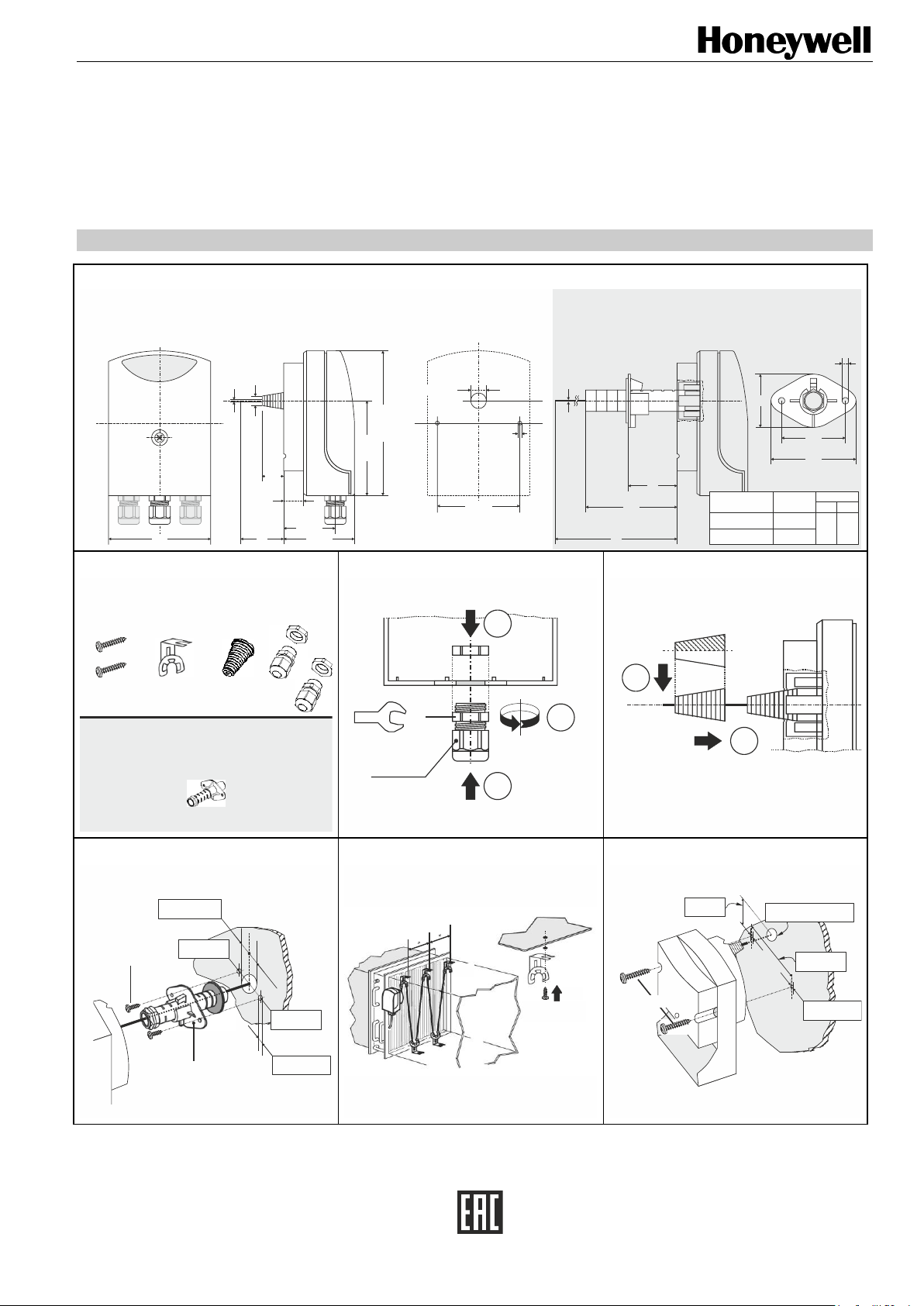
Fig. 1A: Before mounting the FTSE Electronic Frost Protection Thermostat,
remove the housing lid and fit the M16 cable gland(s). Two M16 cable
glands are included in the delivery. The housing features one preexistent hole and two additional knock-outs into which M16 cable
glands may be fitted. Use the O ring included in the delivery to
securely fasten the cable gland into place.
Direct Mounting on the Air Duct or Device Wall
Fig. 1B: Insert the rubber plug into the back of the housing.
Fig. 1E: Mount the housing.
Fig. 1F: Mounting the housing with test loop for function test.
NOTE: The temperature in the test loop must be ≥ the temperature in
the air duct.
Mounting Using a Mounting Flange
Fig. 1C: Mounting flange (R9) suitable for insulated air ducts having walls up to
70 mm thick.
Mounting the Probe Line in the Air Duct
Fig. 1D: Use the holders included in the delivery (FTSE20: 3X; FTSE60: 6X).
The capillary tube must not have any kinks; allow as large a bending
radius as possible (min. 20 mm).
TECHNICAL DATA
MEASURING RANGE: 0 … 15 °C
SETTING RANGE: 1 … 10 °C
VOLTAGE SUPPLY: 24 VAC +10 / -20% SELV, 48 … 63 Hz
VALVE CONTROL INPUT: (Y1) 0 … 10 V, input current max. 0.1 mA
VALVE CONTROL OUTPUT: (Y2) 0 … 10 V, load max. 1 mA
TRANSMITTER OUTPUT: (T) 0 … 15 °C = 0 … 10 V, load max. 1 mA
ELECTRICAL SAFETY: According to DIN EN 60730-2-9. Overvoltage
PROTECTION RATING: I, with internal isolation from SELV circuit
POWER CONSUMPTION: Max. 6.6 VA
ELECTRICAL CONNECTION: Tension spring terminals
CONDUCTOR CROSS-SECTION: Max. 2 x 1.5 mm2 or 1 x 2.5 mm2,
ELECTROMAGNETIC COMPATIBILITY: DIN EN 61326-1
INTERFERENCE EMISSION: Class B
INTERFERENCE IMMUNITY: Industrial requirements
PERMISSIBLE AMBIENT TEMP.: -15 … +55 °C (use)
FUSE PROTECTION: Max. 10 A
RELAY OUTPUT: 230 VAC, 6(2) A; 24 VDC, 0.1 … 6 A
PROTECTION TYPE: IP42 according to EN 60529
MODE OF OPERATION: According to 60730-1, type 1 B
WEIGHT: 2-meter probe line, approx. 0.34 kg; 6-meter probe
APPROVALS: CE,
category III. Pollution degree 2. Rated surge voltage
4.0 kV. Brinell test temperature 125 °C. Software
class A.
min. 1 x 0.25 mm2
-25 … +65 °C (storage)
line, approx. 0.41 kg
ELECTRICAL INSTALLATION
The choice of cable, the installation, and the electrical connection must conform
to the requirements of VDE 0100 "Regulations for the installation of power
circuits with nominal voltages below 1000 V", or to the appropriate local
regulations.
If the relay contacts (NO, COM, NC) are not operated at separated extra-low
voltage (SELV), only authorized and qualified electricians may open the device
for adjustment work or, alternatively, the relay contact must be de-energized.
Wire the installation according to its circuit diagram. If it does not have one, the
circuit diagram given in these instructions may be used as an aid.
Connection suitable for fixed cables, cable routing with strain relief, attachment
type Y, cable gland clamping range 5 to 10 mm.
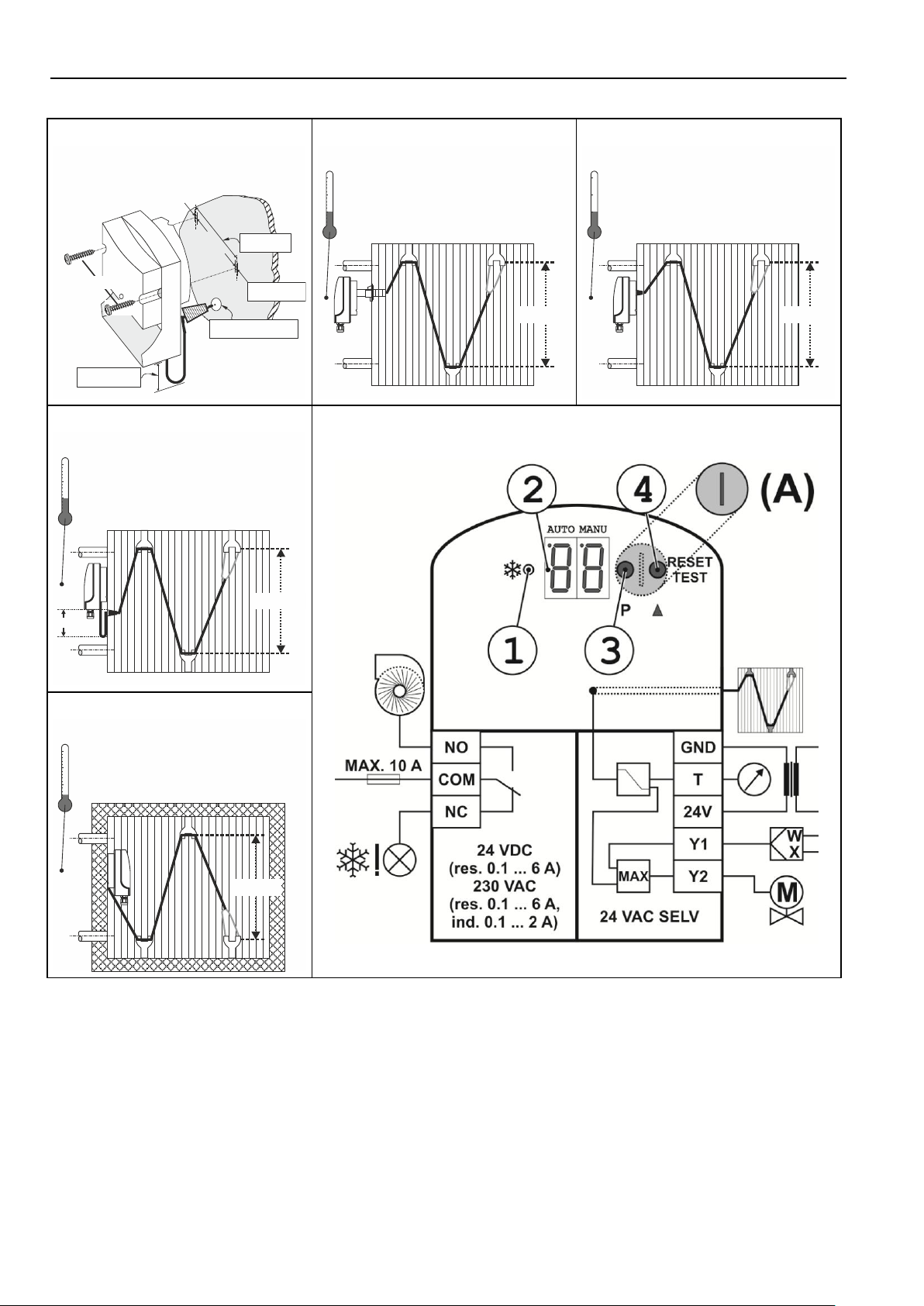
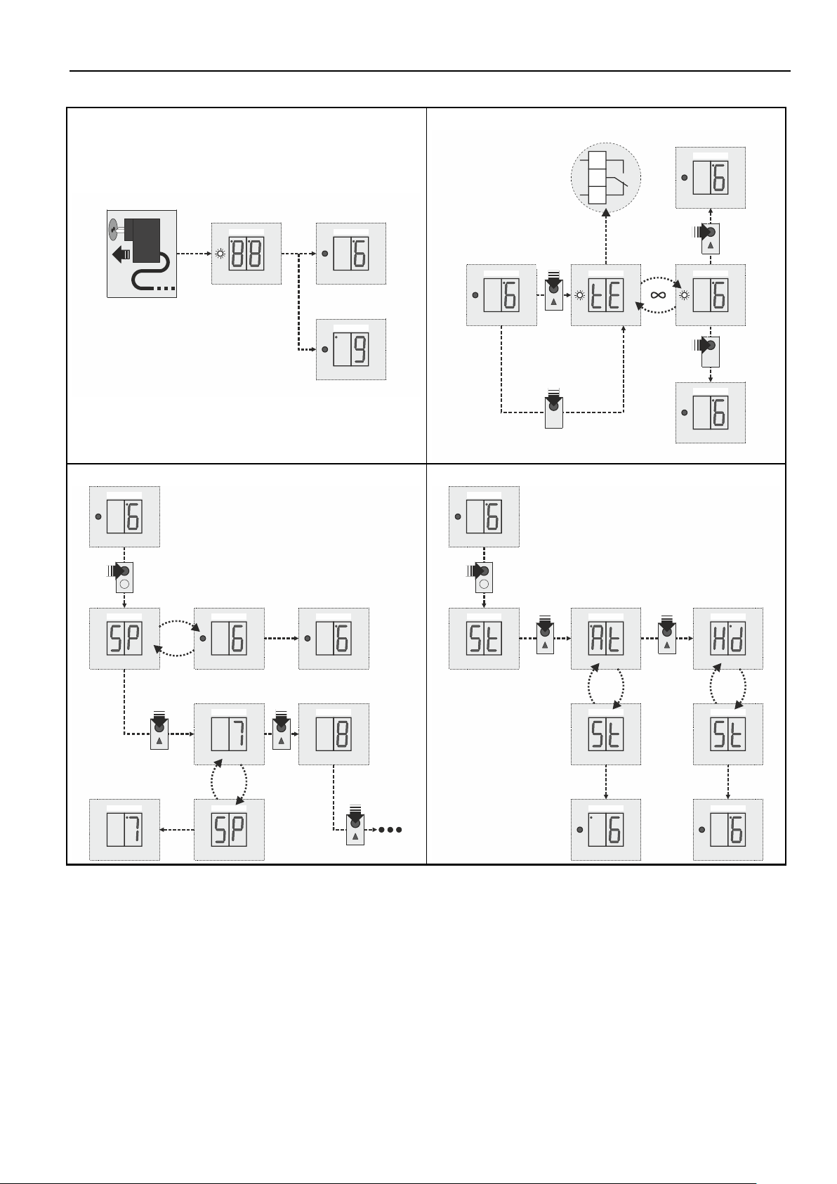
ADJUSTMENTS
Fig. 3: Adjustments can be made using the two buttons (3) and (4) accessible
after unscrewing and removing the sealing screw (A).
The switch-point (SP) is set by pressing the P (PARAMETER) key once and
then pressing the (VALUES) key until the desired value appears in the
display (2). Values are rotational; automatic transfer of values after 2 seconds.
The operating mode (St) is set by pressing the P key twice and then
pressing the key until the desired mode (At or Hd) appears in the display
(2).
At = automatic unlocking (temperature monitor)
Hd = manual unlocking (temperature limiter)
Values are rotational; automatic transfer of values after 2 seconds.
Start-Up
Check wiring according to the installation's circuit diagram.
Check whether the switch-point and operating mode are set correctly.
FUNCTION
Checking the Probe Function
Set the switch-point based on the current probe line temperature.
If required, cool the function loop or another segment of the probe line (at least
250 mm long) to below the switch-point.
The relay contact must switch, and the LED (1) must light up.
The measurement signal voltage can be measured at terminals T and GND
(see Fig. 3). Measuring range: 0 VDC to 10 VDC ≙ 0 … 15 °C.
Test Mode (tE)
The test mode (tE) is set by pressing either the P key or the key for more
than 2 seconds. The display screen then shows "tE" alternating with the
switch-point.
The output relay switches to the "frost" position and the LED (1) will light up.
The valve control signal (terminal Y1) is not affected.
The test mode is switched off again by pressing either key again for 2 seconds
or by interrupting the voltage supply.
Unlocking in "Frost" Position
In the "auto" operating mode, the frost monitor is automatically unlocked as
soon as the temperature rises by approx. 2 K above the switch-point (see Fig.
5).
In the manual operating mode, the output relay remains in the "frost" position. It
can be unlocked by pressing either the P key or the key or by interrupting
the voltage supply.
Indicating a Fault
If the frost monitor has stopped functioning due to a fault in the probe line
(fracture in the capillary tube), the device switches to the "frost" mode. The
relay also switches, and the LED (1) lights up. The display (2) flashes "- -" if the
voltage supply is correct.
5 MU1B-0589GE51 R0915
Page 6

FTSE ELECTRONIC FROST PROTECTION THERMOSTATS – MOUNTING INSTRUCTIONS
Der elektrische Anschluß darf nur von
Fachpersonal durchgeführt werden.
ALLGEMEIN
Diese Anleitung enthält Hinweise, die Sie zu Ihrer eigenen Sicherheit sowie zur
Vermeidung von Sachschäden beachten müssen. Diese Hinweise sind durch
Zeichen unterstützt und werden in dieser Anleitung wie gezeigt verwendet.
Lesen Sie diese Anleitung, bevor Sie das Gerät in Betrieb nehmen. Bewahren
Sie die Anleitung an einem für alle Benutzer jederzeit zugänglichen Platz auf.
Sollten bei der Inbetriebnahme Schwierigkeiten auftreten, bitten wir Sie, keine
Manipulationen vorzunehmen, die Ihren Gewährleistungsanspruch gefährden
können.
MONTAGEORT
Fühlerleitung in Luftrichtung nach dem ersten wassergefüllten und
frostgefährdeten Lufterwärmer installieren.
MONTAGE
Abb. 1A: Vor der Montage des FTSE Elektronischen Frostschutzthermostats
den Gehäusedeckel abnehmen und die M16-Kabelverschraubungen
einsetzen. In der Lieferung sind zwei M16-Kabelverschraubungen
enthalten. Das Gehäuse weist ein fertiges Loch sowie zwei zusätzliche Durchbrüche auf, in die die M16-Kabelverschraubungen eingesetzt werden können. Die Befestigungsschraube mit dem beigelegtem O-Ring sichern.
Direktmontage auf die Kanal- oder Gerätewand
Abb. 1B: Gummizapfen in Gehäuserückseite einsetzen.
Abb. 1E: Gehäuse montieren.
Abb. 1F: Montage mit Testschlaufe für Funktionstest.
HINWEIS: Die Temperatur an der Testschlaufe muß gleich oder höher
der Temperatur am Kanal sein.
Montage mit Montageflansch
Abb. 1C: Der Montageflansch (R9) ist für Luftkanäle mit bis zu 70 mm
Isolierung geeignet.
Fühlerleitungsmontage im Luftkanal
Abb. 1D: Verwenden Sie die in der Lieferung enthaltenen Halterungen
(FTSE20: 3X; FTSE60: 6X). Das Kapillarrohr darf nicht geknickt
werden: minimaler Biegeradius: 20 mm.
TECHNISCHE DATEN
MESSBEREICH: 0 … 15 °C
EINSTELLBEREICH: 1 … 10 °C
SPANNUNGSVERSORGUNG: 24 VAC +10 / -20% SELV, 48 … 63 Hz
EINGANG VENTILSTEUERUNG: (Y1) 0 … 10 V, Eingangsstrom max. 0.1 mA
AUSGANG VENTILSTEUERUNG: (Y2) 0 … 10 V, Belastung max. 1 mA
AUSGANG MESSUMFORMER: (T) 0 … 15 °C = 0 … 10 V, Belastung max. 1 mA
ELEKTRISCHE SICHERHEIT: nach DIN EN 60730-2-9. Überspannungskategorie
SCHUTZKLASSE: I, mit interner Trennung zu SELV-Stromkreis
LEISTUNGSAUFNAHME: max. 6.6 VA
ELEKTRISCHER ANSCHLUSS: Zugfederklemmen
LEITUNGSQUERSCHNITT: max. 2 x 1.5 mm2 oder 1 x 2.5 mm2,
ELEKTROMAGN. VERTRÄGLICHKEIT: DIN EN 61326-1
STÖRAUSSENDUNG: Klasse B
STÖRFESTIGKEIT: Industrieanforderung
ZUL. UMGEBUNGSTEMPERATUR: -15 … +55 °C (im Gebrauch)
ERFORDERLICHE ABSICHERUNG: max. 10 A
RELAISAUSGANG: 230 VAC, 6(2) A; 24 VDC, 0.1 … 6 A
SCHUTZART: IP42 nach EN 60529
WIRKUNGSWEISE: nach 60730-1, Typ 1 B
GEWICHT: 2-m Fühlerleitung, ca. 0.34 kg; 6-m Fühlerleitung,
ZULASSUNGEN: CE,
III. Verschmutzungsgrad 2.
Bemessungsstoßspannung 4.0 kV. Temperatur der
Kugeldruckprüfung 125 °C. Softwareklasse A.
min. 1 x 0.25 mm2
-25 … +65 °C (zur Lagerung)
ca. 0.41 kg
ELEKTRISCHE INSTALLATION
Bei der Wahl des Leitungsmaterials, bei der Installation und beim elektrischen
Anschluß des Gerätes sind die Vorschriften der VDE 0100 "Bestimmungen
über das Errichten von Starkstromanlagen mit Nennspannungen unter 1000 V"
bzw. die jeweiligen Landesvorschriften zu beachten.
Werden die Relaiskontakte (NO, COM, NC) nicht mit einer Kleinspannung
(SELV) betrieben, darf das Gerät für Einstellarbeiten nur vom autorisierten
Elektrofachpersonal geöffnet werden - oder der Relaiskreis muß spannungfrei
sein.
Verdrahtung nach Anschlußplan durchführen. Fehlt dieser, kann der Schaltplan
dieser Anleitung zu Hilfe genommen werden.
Anschlußverbindung geeignet für fest verlegte Leitungen, Leitungsführung mit
Zugentlastung, Anbringungsart Y, Klemmbereich Kabelverschraubung 5 bis 10
mm.
EINSTELLUNGEN
Abb. 3: Einstellungen sind über die beiden Taster (3) und (4) möglich, die
nach Öffnen der Verschlußschraube (A) zugänglich werden.
Der Schaltpunkt (SP) wird durch einmaliges Betätigen der P (PARAMETER)
Taste und anschließend durch Betätigen der (WERTE) Taste gewählt, bis
der gewünschte Wert in der Anzeige (2) erscheint. Werte umlaufend,
automatische Wertübernahme nach 2 Sekunden.
Die Betriebsart (St) wird durch zweimaliges Betätigen der P Taste und
anschließend durch Betätigen der Taste gewählt, bis die gewünschte
Betriebsart (At oder Hd) in der Anzeige (2) erscheint.
At = automatische Entriegelung (Temperaturwächter)
Hd = manuelle Entriegelung (Temperaturbegrenzer)
Werte umlaufend, automatische Wertübernahme nach 2 Sekunden.
Inbetriebnahme
Verdrahtung nach Anschlußplan überprüfen.
Kontrolle, ob Schaltpunkt und Betriebsart richtig eingestellt sind.
FUNKTION
Prüfen der Fühlerfunktion
Schaltpunkt über die aktuelle Temperatur der Fühlerleitung einstellen.
Wenn nötig: Funktionsschlaufe oder ein anderes Stück Fühlerleitung (min. 250
mm lang) unter den eingestellten Schaltpunkt abkühlen.
Der Relaiskontakt muß umschalten, die LED (1) muß aufleuchten.
Die Meßsignalspannung kann an den Klemmen T und GND (siehe
Anschlußplan) gemessen werden (Meßbereich: DC 0 bis 10 V ≙ 0 bis 15 °C).
Testbetrieb (tE)
Durch Betätigen entweder der P Taste oder der Taste länger als 2
Sekunden wird der Testmodus (tE) ausgewählt. Das Display zeigt
abwechselnd "tE" und den eingestellten Schaltpunkt.
Das Ausgangsrelais schaltet in die Frostposition und die LED (1) leuchtet auf.
Das Ventilsteuersignal (Y1) wird nicht beeinflußt.
Der Testmodus wird durch erneutes Betätigen einer beliebigen Taste länger als
2 Sekunden abgeschaltet oder durch Unterbrechung der
Versorgungsspannung.
Entriegeln in der Froststellung
In der Betriebsart "Auto" wird der Frostwächter automatisch entriegelt, sobald
die Temperatur um ca. 2 K über den Schaltpunkt ansteigt (siehe Abb. 5).
In der Betriebsart "Manu" bleibt die Froststellung erhalten. Sie ist durch
Betätigen entweder der P Taste oder der Taste oder durch Unterbrechung
der Versorgungsspannung zu entriegeln.
Anzeige eines Defekts
Ist die Funktion des Frostwächters, auf Grund eines Defektes an der Fühlerleitung (Kapillarbruch) nicht mehr gegeben, so schaltet das Gerät in den
Frostbetrieb, das Relais hat geschaltet, die LED (1) leuchtet. Das Display zeigt
blinkend "- -", bei ordnungsgemäßer Spannungsversorgung.
MU1B-0589GE51 R0915 6
Page 7

FTSE ELECTRONIC FROST PROTECTION THERMOSTATS – MOUNTING INSTRUCTIONS
Le raccordement électrique ne doit être
effectué que par du personnel qualifié.
GENERALITES
Cette notice contient des instructions dont vous devez tenir compte aussi bien
pour assurer votre propre sécurité que pour éviter des dégâts matériels. Ces
instructions sont appuyées par des pictogrammes et sont utilisées dans cette
notice comme indiqué.
Lisez cette notice avant de mettre en service l’appareil. Conservez-la dans un
endroit accessible à tout moment par l’ensemble des utilisateurs.
Si vous rencontrez des difficultés lors de la mise en service, ne procédez à
aucune manipulation qui pourrait compromettre votre droit à la garantie.
PLACE DE LA MONTAGE
Placer le câble de la sonde dans le sens de l'air après le premier réchauffeur
d'air rempli d'eau et gelé.
MONTAGE
Fig. 1A: Retirer le couvercle du boîtier avant le montage du contrôleur de gel,
puis installer les presse-étoupes M16. Les deux presse-étoupes M16
sont inclus à la livraison. Le boîtier comporte un trou pré-existant et
deux pré-découpes supplémentaires dans lesquels les presseétoupes M16 peuvent être placés. Utiliser le joint torique fourni pour
ne pas perdre la vis de fixation.
Montage direct sur la paroi du canal ou de l'appareil
Fig. 1B: Insérer le tenon en caoutchouc à l'arrière du boîtier.
Fig. 1E: Monter le boîtier.
Fig. 1F: Montage avec boucle d'essai pour test de fonctionnement.
NOTA: La température sur la boucle d'essai doit être supérieure ou
égale à la température au niveau du canal.
Montage avec bride de fixation
Fig. 1C: Bride de fixation (R9) adaptée aux gaines de ventilation avec isolation
avec épaisseur de paroi pouvant atteindre jusqu'à 70 mm.
Montage du câble de la sonde dans la gaine de ventilation
Fig. 1D: Montage avec fixation inclus à la livraison (FTSE20: 3X; FTSE60: 6X).
Le tube capillaire ne doit pas être plié; grand rayon de courbure si
possible.
CARACTERISTIQUES TECHNIQUES
ETENDUE DE MESURE: 0 … 15 °C
PLAGE DE REGLAGE: 1 … 10 °C
ALIMENTATION: 24 V CA +10 / -20% SELV, 48 … 63 Hz
ENTREE DE COMMANDE DU CLAPET: (Y1) 0 … 10 V,
SORTIE DE COMMANDE DU CLAPET: (Y2) 0 … 10 V, charge max. 1 mA
SORTIE CONVERTISSEUR DE MESURE: (T) 0 … 15 °C = 0 … 10 V,
SECURITE ELECTRIQUE: suivant DIN EN 60730-2-9. catégorie de surtension
CLASSE DE PROTECTION: I, avec isolement interne par rapport aux circuits
PUISSANCE ABSORBEE: Max. 6.6 VA
RACCORDEMENT ELECTRIQUE: Bornier avec système anti-arrachement
SECTION DE FIL: Max. 2 x 1.5 mm2 ou 1 x 2.5 mm2,
COMPATIBILITE ELECTROMAGNET.: DIN EN 61326-1
EMISSION DE PARASITES: Classe B
RESISTANCE AUX PARASITES: Normes industrielles
TEMPÉRATURES AMB. ADMISSIBLES: -15 … +55 °C (En service)
PROTECTION PAR FUSIBLES: Disjoncteur max. 10 A
SORTIE RELAIS: 230 V CA, 6(2) A; 24 V CC, 0,1 … 6 A
INDICE DE PROTECTION: IP42 suivant EN 60529
MODE D'ACTION: suivant 60730-1, type 1 B
POIDS: 2 m de câble de sonde, 0,34 kg env.,
courant d'entrée max. 0.1 mA
charge max. 1 mA
III. degré de pollution 2. surtension transitoire
assignée 4.0 kV. température de la sonde 125 °C.
classe de logiciel A.
SELV
min. 1 x 0.25 mm2
-25 … +65 °C (Pour stockage)
6 m de câble de sonde, 0,41 kg env.
INSTALLATION ELECTRIQUE
Il faut respecter la réglementation VDE 0100 en vigueur "Prescriptions à propos
des installa- tions à courant fort avec tensions nominales 1000 V" aussi bien
pour le choix du matériau des câbles que pour l’installation ou le raccordement
électrique.
Lorsque les contacts de relais (NO, COM, NC) ne fonctionnent pas avec une
basse tension (SELV), seul un personnel qualifié autorisé peut ouvrir l'appareil
pour effectuer des réglages ou le circuit de relais doit être mis hors tension.
Effectuer le câblage suivant le plan électrique de l'installation. S'il n'y en a pas,
il est possible d'utiliser le plan de cette notice.
Raccordement adapté à des câbles posés fixes, câblage avec décharge de
traction, mise en place Y, domaine de serrage presse-étoupe 5 à 10 mm.
REGLAGES
Fig. 3: Les réglages sont possibles via les deux boutons-poussoirs (3) et (4)
après ouverture du bouchon fileté (A).
Le point de commutation (SP) en appuyant une fois sur la touche P
(PARAMETRE puis en sélectionnant la touche (VALEURS) jusqu’à la valeur
souhaité dans l’affichage (2). Les valeurs sont rotationnelles : validation
automatique après 2 secondes.
Le mode de fonctionnement (St) est défini en appuyant deux fois sur la
touche P et en appuyant sur la touche jusqu’à ce que le mode souhaité
(At or Hd) apparaisse dans l’affichage (2).
At = Déverrouillage automatique (contrôleur de température)
Hd = Déverrouillage manuel (limiteur de température)
Les valeurs sont rotationnelles : validation automatique après 2 secondes.
Mise en service
Vérifier le câblage d'après le plan électrique de l'installation.
Vérifier si le point de commutation et le mode de fonctionnement sont
correctement réglés.
FONCTION
Vérifier le fonctionnement du capteur
Régler le point de commutation via la température actuelle du câble de la
sonde.
Si nécessaire refroidir la boucle de fonctionnement ou une partie du câble de la
sonde (min. 250 mm de long) sous le point de commutation réglé.
Le contact de relais doit commuter, la LED (1) doit s'allumer.
Il est possible de mesurer la tension du signal de mesure aux bornes T et GND
(voir Fig. 3). Etendue de mesure: 0 V CC à 10 V CC ≙ 0 … 15 °C.
Le mode test (tE)
Le mode test (tE) est sélectionné en appuyant sur la touche P ou plus de
2 secondes. L'écran af- fiche en alternance „tE“ et le point de commutation
réglé. L'écran af- fiche en alternance "tE" et le point de commutation réglé.
Le relais de sortie se met en position de gel et le LED (1) s’allumera. Le signal
de commande de la soupape (borne Y1) n'est pas impacté.
Le mode test est désactivé seulement après avoir réappuyé sur une touche de
son choix plus de 2 secondes ou après mise hors tension.
Déverrouillage en position gel
En mode „Auto“ le contrôleur de gel est automatiquement déverrouillé, dès que
la température augmente d'env. 2K au dessus du point de commutation (voir
Fig. 5).
En mode „Manu“ la position gel est maintenue. Elle peut être déverrouillée en
actionnant la touche P ou ou après mise hors tension.
Affichage d'un défaut
Lorsque la fonction contrôleur de gel n'est plus assurée en raison d'un défaut
au niveau du câble de la sonde (rupture de capillaire) alors l'appareil commute
en mode gel, le relais a commuté, la LED (1) s'allume. "- -" s'affiche à l'écran
en clignotant, lorsque l'alimentation est conforme.
ADMISSION: CE,
7 MU1B-0589GE51 R0915
Page 8

FTSE ELECTRONIC FROST PROTECTION THERMOSTATS –MOUNTING INSTRUCTIONS
La conexión eléctrica solo debe ser
ejecutada por personal especializado.
GENERALIDADES
Este manual contiene indicaciones que deben ser tenidas en cuenta para su
propia seguridad y evitar daños materiales. Estas indicaciones están ilustradas
con signos que se utilizan en este manual de la forma siguiente.
Por favor, lea este manual antes de poner el aparato en marcha. Conserve el
manual en un lugar accesible para todos los usuarios en cualquier momento.
En caso de surgir dificultades durante la puesta en marcha, les rogamos se
abstengan de realizar manipulaciones que puedan poner en peligro su derecho
a garantía.
EMPLAZAMIENTO DE MONTAJE
Instalar la línea de capilar en dirección del aire después del primer calentador
de aire lleno de agua y expuesto a congelación.
MONTAJE
Fig. 1A: Antes del montar el detector antihielo, quitar la tapa de la carcasa y
colocar los atornillamientos M16. Se incluyen dos atornillamientos
M16 como parte del material que se entrega. La carcasa tiene un
orificio preexistente y dos orificios ciegos adicionales en los que
pueden instalarse los atornillamientos de cable M16. Asegurar el
tornillo de sujeción contra pérdida con la junta tórica adjunta. apriete
el atornillamiento en su posición de forma segura.
Montaje directo sobre la pared del conducto o del instrumento
Fig. 1B: Colocar los tacos de goma en la parte trasera de la carcasa.
Fig. 1E: Montar la carcasa.
Fig. 1F: Montaje con bucle de comprobación para prueba de función.
Indicación: La temperatura en el bucle de comprobación debe ser
igual o mayor a la temperatura en el conducto.
Montaje con brida de montaje
Fig. 1C: Brida de montaje (R9) apropiada para conductos de aire con
aislamiento hasta 70 mm de grosor de pared.
Montaje de la línea capilar en el conducto de aire
Fig. 1D: con sujeción incluida en la entrega (FTSE20: 3X; FTSE60: 60). El
tubo del capilar no se debe doblar; radio de curvatura lo más amplio
posible.
DATOS TÉCNICOS
CAMPO DE MEDICIÓN: 0 … 15 °C
CAMPO DE AJUSTE: 1 … 10 °C
ALIMENTACIÓN DE TENSIÓN: 24 VAC +10 / -20% SELV, 48 … 63 Hz
ENTRADA, CONTROL DE VÁLVULAS: Y1 0 … 10 V, corriente de entrada max. 0.1 mA
SALIDA CONTROL DE VÁLVULAS: Y2 0 … 10 V, carga max. 1 mA
SALIDA CONV. DE MEDICIÓN: T 0 … 15 °C = 0 … 10 V, carga max. 1 mA
SEGURIDAD ELÉCTRICA: según DIN EN 60730-2-9. categoría de sobre-
CLASE DE PROTECCIÓN: I, con separación interna al circuito eléctrico SELV
CONSUMO DE POTENCIA: max. 6.6 VA
CONEXIÓN ELÉCTRICA: Bornes de muelle de tracción
SECCIÓN DE CABLE: max. 2 x 1.5 mm2 o 1 x 2.5 mm2, min. 1 x 0.25 mm2
COMP. ELECTROMAGNÉTICA: DIN EN 61326-1
EMISIÓN DE INTERFERENCIAS: Clase B
RESISTENCIA A LAS INTERFERENCIAS: Exigencia industrial
TEMP. DE ENTORNO PERMITIDAS: -15 … +55 °C (en uso)
SEGURIDAD NECESARIA: Interruptor del circuito max. 10 A
SALIDA DE RELÉ: 230 VCA, 6(2) A; 24 VCC, 0.1 … 6 A
TIPO DE PROTECCIÓN: IP42 según EN 60529
MODO DE ACCIÓN: según 60730-1, tipo 1 B
PESO: 2 m de capilar, aprox. 0,34 kg,
ADMISIÓN: CE,
tensión III, grado de contaminación 2, tensión
transitoria asignada 4,0kV, temperatura del ensayo
por presión por bolas 125° C, clase software A.
-25 … +65 °C (en almacenaje)
6 m de capilar , aprox. 0,41 kg
INSTALACIÓN ELÉCTRICA
En la elección del material conductivo, en la instalación y en la conexión
eléctrica del aparato se deben cumplir las normas de VDE 0100 "Disposiciones
sobre el montaje de instalaciones de alto voltaje con tensiones nominales
inferiores a 1000 V" resp. las normas estatales correspondientes.
Si los contactos de relee (NO, COM, NC) no se operan en baja tensión (SELV),
el instrumento solo debe ser abierto para tareas de mantenimiento por personal eléctrico especializado autorizado o el relee debe estar libre de tensión.
Ejecutar el cableado según el diagrama de conexiones de la instalación. Si no
se tuviera, se puede utilizar el diagrama de conexiones de este manual.
La conexión es adecuada para conexiones fijas, tendido de líneas con
descarga de tracción, tipo de montaje Y, campo de apriete del atornillamiento
de cables 5 a 10 mm.
AJUSTES
Fig. 3: Los ajustes son posibles a través de ambos botones (3) y (4) después
de abrir el tornillo (A).
El punto de conmutación (SP) pulsando una vez el botón P (PARÁMETRO) a
continuación selección del punto de conmutación con el botón (VALORES)
hasta que el valor deseado aparezca en la pantalla (2). Valores cíclicos,
aceptación automática de valores después de 2 segundos.
El modo de funcionamiento (St) pulsando dos veces el botón P a continuación selección del modo de funcionamiento con el botón hasta que el
modo deseado (At o Hd) aparezca en la pantalla (2).
At = Desbloqueo automático (control de temperatura)
Hd = Desbloqueo manual (limitador de temperatura)
Valores cíclicos, aceptación automática de valores después de 2 segundos.
Puesta en funcionamiento
Comprobar cableado según diagrama de conexiones de la instalación.
Control sobre el ajuste correcto del punto de conmutación y modo de
funcionamiento.
FUNCIÓN
Comprobación de la función de la sonda
Ajustar el punto de conmutación por encima de la temperatura actual de la
línea de capilar.
En caso necesario: enfriar el bucle de función u otro tramo de la línea capilar
(min. 250 mm de longitud) por debajo del punto de conmutación ajustado.
El contacto de relee debe conmutar, la LED (1) se debe encender.
La tensión de la señal de medición puede medirse en los bornes T y GND (ver
Fig. 3) (campo de medición: DC 0 a 10 V ≙ 0 a 15 °C).
Funcionamiento de prueba (tE)
Pulsando el botón P o durante más de 2 segundos, se selecciona el modo
de comprobación (tE). La pantalla muestra alternativamente "tE" y el punto de
conmutación ajustado.
El relé de salida conmuta a la posición congelante. La señal de control de
válvula (borne Y1) no se ve afectada.
El modo de comprobación se desconecta pulsando de nuevo cualquier botón
durante más de 2 segundos o interrumpiendo la tensión de alimentación.
Desbloqueo de la posición de congelación
En el modo de funcionamiento „Auto“ el detector de congelación se
desbloquea automáticamente en cuanto la temperatura sube aprox. 2K por
encima del punto de conmutación (consultar Fig. 5).
En el modo de funcionamiento „Manu“, se conserva la posición de congelación.
Èsta se desbloquea pulsando el botón P o o interrumpiendo la tensión de
alimentación.
Indicación de defecto
Si la función del detector de congelación se ve interrumpida por un defecto en
la línea capilar (rotura de capilar), el instrumento conmuta al funcionamiento de
congelación, el relee ha con- mutado, la LED (1) luce. La pantalla muestra con
parpadeo "- -", con alimentación de tensión correcta.
Manufactured for and on behalf of the Environmental and Combustion Controls Division of Honeywell Technologies Sàrl, Rolle, Z.A. La Pièce 16, Switzerland by its Authorized Representative:
FEMA Control
Honeywell GmbH
Böblinger Strasse 17
71101 Schönaich, Germany
Phone: +49 (0) 7031 637 01, Fax: +49 (0) 7031 637 740
http://www.fema.biz
MU1B-0589GE51 R0915 Subject to change without notice
 Loading...