

Honeywell FTS015 DATASHEET
4
2
Temperature transmitters
Two-phase frost protector
Two-phase frost protector Type
series FTS
with limiter contact and integrated priority selection
FTS015
Technical data
Supply voltage 24 VAC ± 20 % or
Output signal 0–10
Power consumption max. 1 W
Cable entry M16 x 1.5 for output
Degree of protection IP 65
Mounting With 2 x 4 mm screws
Ambient temperature 12 to 50°C
Switching capacity 8 A, 250 VAC
24–36 VDC
V ± 1 mA (with
falling temperature)
+
floating limiter
contact
signal 0–10 V
Plug connection to
DIN 43650 for limit
witch
value s
directly on the duct
wall. 5 capillary tube
holders type H
included
Please note: at ambient temperatures
below 10°C the unit
responds and signals
“risk of frost”
3 are
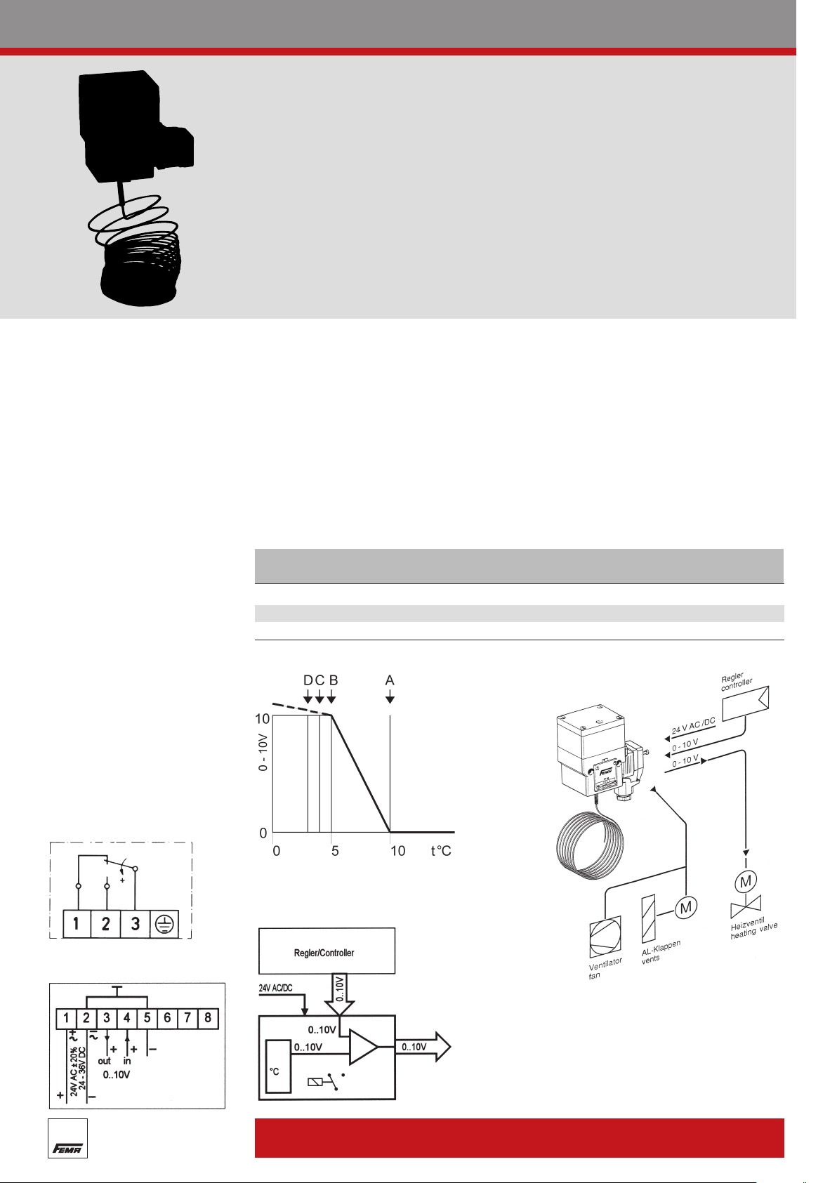
With falling temperature the frost protector generates a rising output signal from 0–10 V.
If the temperature continues to fall, a limiter
contact (single-pole changeover contact) is
actuated.
If the output signal of the controller (Y signal) is looped through the frost protector, a maximum selection of the two signals takes place. If the Y signal from the controller is greater than the output signal
of the frost protector, the controller determines the position of the heating valve (normal operation). If
the output signal of the frost protector is greater than the Y signal of the controller (risk of frost), then
ost protector determines the position of the heating valve, as long as “risk of frost” is signalled by
the fr
the sensor. When there is no longer any risk of frost, the controller automatically resumes control of
the heating valve.
nal priority selection is therefore not required. The sensor acting over the entire length is self-
Exter
monitoring, i.e. in the event of breakage or damage to the capillary tube, “risk of frost” is signalled.
If the signal of the controller is not looped through, the FTS outputs the signal of the frost protector.
Product Summary
Type Range of action Capillary tube
FTS 015 +10 to +3°C 6 m
FTSB 015 +10 to +3°C 3 m
Characteristics
Connection scheme
(plug connection)
Connection scheme
(ter
minal connection)
Output
For frost protection thermostats, see page 28
Schematic diagram
Specification
Two-phase frost protector with limiter contact and integrated
maximum selection for monitoring the surface of the air heater,
input signal: 0–10 V, output signal: 0–10 V ± 1 mA + single-pole
changeover s
Sensor Relay Comparator
s
pillary tube length 3/6 m.
Ca
witch.
Degree of protection:
IP 65
 Loading...