

Page 1
Mechanical Thermostats
1
8
Technical data
Mechanical thermostats
Principal technical data
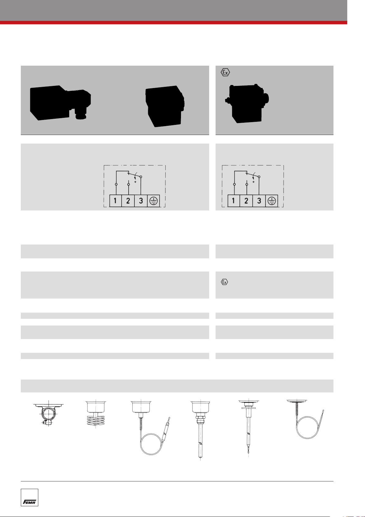
Standard version Terminal connection -version
…200 …300 …700
Switch housing
Switching function Floating change-over contact Floating changeover contact.
and connection drawing With rising pressure switching single-pole With rising pressure switching single-pole
(applies only to version from 3–1 to 3–2 from 3–1 to 3–2
with microswitch)
Switching capacity 8 A at 250 VAC 3 A at 250 VAC
(applies only to version 5 A at 250 VAC inductive 2 A at 250 VAC inductive
with microswitch) 8 A at 24 VDC 3 A at 24 VDC
Mounting position vertical or horizontal vertical
Degree of protection IP 54 (terminal connection IP 65) IP 65
(in vertical position)
Explosion protection – EEx de IIC T6
Code – II 2 G D EEx de IIC T6 IP65 T80° C
ype Examination –
EC T
Certificate Number
Electrical connection
Cable entr
Ambient temperature -15 to +70 °C -15 to +60 °C
Switching point Adjustable with spindle. Adjustable with spindle after
Switching differential Adjustable or not adjustable Not adjustable
Medium temperatur
Vibration strength No significant deviations up to 4 g.
Isolation values Overvoltage category III, contamination class 3, reference surge voltage 4000 V.
Sensor systems
y
e
Diecast aluminIum GDAISi 12 Diecast aluminIum GDAISi 12
0.3 A at 250 VDC 0.03 A at 250 VDC
min. 10 mA, 12 VDC min. 2 mA, 24 VDC
preferably vertical
PTB 02 A
Plug connection to DIN 43650/ Terminal connection
Terminal connection
PG 11 / for ter
(see Product Summary)
Max. 70
At higher accelerations the switching differential is reduced slightly.
Use over 25 g is not per
Confor
minal connection M 16 x 1.5
C
C, briefly 85
°
mity to DIN VDE 0110 (01.89) is confir
°
mitted.
M 16 x 1.5
the terminal box lid is removed.
Max. 60 °C
med.
TEX 1121
Strap-on sensor
TKM
Room sensor
TRM
Capillary tube sensor
AM
T
Rod sensor
TX + R 1
Air duct sensor
TX + R 6
Frost protection sensor
FT
Page 2
Mechanical Thermostats
Temperature monitoring
Temperature monitoring
n explosion-endangered areas
i
T
emperature switches with special equipment can also be used in
explosion risk area ≥ Zone 1 (21).
The following alternatives are possible:
1. Thermostats with pressure-proof encapsulated switching device,
degree of protection II 2 G/D EEx de IIC T6 IP65 T 80°C
The thermostat in pressure-proof encapsulation can be used directly in explosion risk areas ≥ Zone 1
(21). The maximum switching voltage, switching capacity and ambient temperature must be taken into
account and the rules for installation in the explosion risk area must be observed.
All thermostats may be equipped with explosion-proof switching devices. However, special circuits
and designs with an adjustable switching differential are not permitted.
2. Thermostats in EExi version
mostats in the standard version can be used in explosion risk areas ≥ Zone 1, if they are incor-
All ther
porated into an “intrinsically safe circuit”. Intrinsic safety is based on the principle that the control current circuit in the explosion risk area carries only a small quantity of energy which is not capable of
generating an ignitable spark.
Isolating amplifiers, e.g. type Ex 011, must be tested by the Physikalisch-Technische Bundesanstalt
(PTB) pursuant to ATEX 100 and approved for use in explosion risk areas. Isolating amplifiers must in
any event be installed outside the explosion risk area.
Thermostats which are intended for EEx-ia installations are equipped with blue terminals and cable
entries. In view of the low voltages and currents carried via the contacts of the microswitches, goldplated contacts are used in the EX-i version (additional function ZFT 513).
1
9
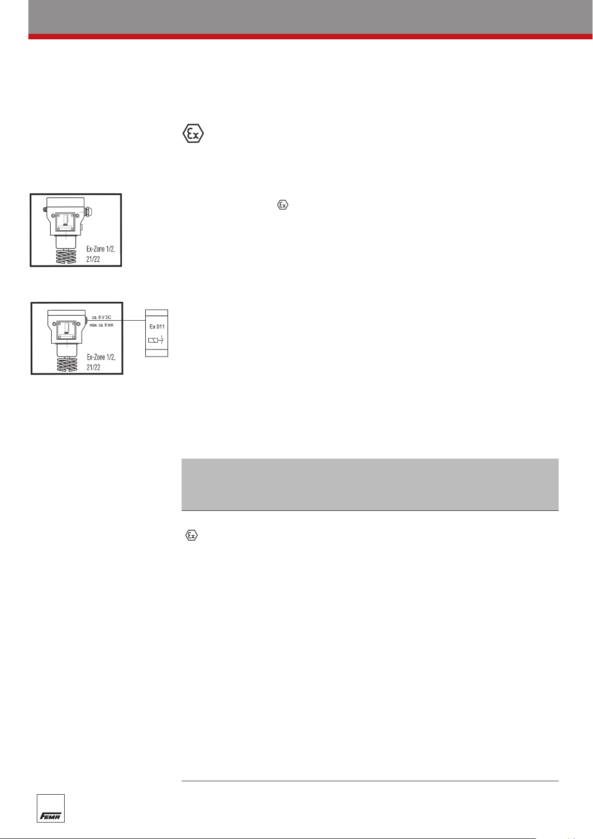
Temperature monitoring in Zone 1 (21) and 2 (22)
essure-proof encapsulated
Pr
Ex-de …
Explosion protection:
II 2 G/D EEx de IIC T6 IP 65 T80° C
ATEX approval for the
complete switching device
Thermostats with silver contact
Switching capacity:
max. 3 A, 250 V
min. 2 mA, 24 VDC
AC
Intrinsically safe
D …-513 +Ex 011
Explosion protection:
EEx-ia
ATEX approval for isolating amplifier
Ex 011
Thermostats with gold-plated
contacts, blue terminals and
blue cable entries.
Switching capacity:
Information for devices with additional function
ZF 513, ZF 574, ZF 576 to EN 50020:
i
= 10 VDC
U
i
= 20 mA
I
i
= 0 µH
L
i
= 0 pF
C
max. 100 mA, 24 VDC
min. 2 mA, 5 VDC
The thermostat can be installed
within the Ex-Zone.
The isolating amplifier must be installed
outside the Ex-Zone.
Page 3

2
8
Mechanical Thermostats
Frost protection thermostats
Frost protection thermostats
Type series FT
for air heating and conditioning systems
FT015
Technical data
p
(
plicable to Ex versions)
not a
Body Diecast aluminium GD
Sensor Cu capillary tube
Max. ambient +70°C
temperature at +60°C for Ex versions
switching device
Contact arrangement
Switching capacity 8 (5) A 250 VAC
Degree of protection IP 54 according to
Switching differential approx. 4 K, preset in
Calibration Scale value corre-
Plug connection Angled plug, 3-prong
erminal connection
T
Al Si 12 according to
DIN 1725.
Single-pole
changeover switch
DIN 40050 (with
vertical installation)
factory
sponds to the lower
witching point (with
s
falling temperature),
the upper switching
point is higher by the
amount of the switching differential
+ earth contact,
to DIN 43650.
Cable entry Pg 11.
Max. cable diameter
10 mm, cable outlet
possible in
spaced 90
Supplied with plug.
M16 x 1.5 for Ex devices
4 directions
part.
a
°
Dimensions
With FT frost protection thermostats, it is necessary to ensure that the ambient temperature at
the switching device does not fall below the
d
efined switching point. Also, parts of the
capillary tube outside the air heater must not be
laid in zones whose temperature may fall below
the defined switching point. Either situation
w
ould cause the device to cut out prematurely.
FEMA frost protection thermostats reliably monitor the temperature in hot-water-heated air heaters. If
the temperature falls below the set value, the thermostat switches off. A visual or audible “frost hazard” alarm can be switched on at the same time. A fixed stop on the setting spindle at 3°C prevents
the thermostat from being set below the freezing point due to inexpert adjustment.
If the capillar
y tube is damaged or broken, FEMA frost protection thermostats reliably switch off
towards the safe side (e.g. fan off) irrespective of the temperature at the sensor.
i
Operating method
frost protection thermostats with 3 m or 6 m capillary tube detect the temperature over the whole
FT
length of the capillary tube and are therefore able to monitor the surface of the whole air heater. If the
capillary tube becomes too cold at any point, the thermostat switches off.
Frost protection thermostats with reclosing lockout (switching unit 206) break the circuit at the
set value when the temperature falls. The adopted switching state is mechanically latched against
automatically switching on again.
The latch can only be released by pressing the unlocking button after the temperature has risen again
by approx. 8°C.
Product Summary
Type with reclosing Setting Max. temperature Version
lockout
range
at sensor
FT 015 FT 015-206 +4 to +15°C +200°C 6 m capillary tube
FTB 015 FTB 015-206 +4 to +15°C +200°C 3 m capillary tube
Two-phase frost protection control with output signal 0–10 V and limit switch.
See separate data sheet, FTS, page 42.
-version · Degr
ype
T
ee of protection II 2 G/D EEx de IIC T6 IP65 T 80°C
Setting range Max. temperature Version
at sensor
Ex-FT 015 +4 to +15°C +130°C 6 m capillary tube
Ex-FTB 015
+4 to +15
C
°
+130°C 3 m capillary tube
Specification
Frost protection thermostat type … with 3 m / 6 m capillary tube for monitoring the surface
of the air heater
. Range of adjustment 4 to 15°C with/without internal mechanical interlock.
Diecast aluminium casing with plug connection to DIN 43650.
s
Degree of protection:
IP 54/65
 Loading...