

Page 1

HONEYWELL EXCEL 5000 OPEN SYSTEM
Excel 50
CONTROLLER
INSTALLATION INSTRUCTIONS
Copyright © 2009 Honeywell Inc. • All Rights Reserved EN1B-0101GE51 R0909G
Page 2

EXCEL 50 INSTALLATION INSTRUCTIONS
Trademark Information Echelon, LON, L
LonTalk, LonUsers, LonPoint, Neuron, 3120, 3150, the Echelon logo, the L
logo, and the LonUsers logo are trademarks of Echelon Corporation registered in
the United States and other countries. LonLink, LonResponse, LonSupport, and
LonMaker are trademarks of Echelon Corporation.
ONMARK, LONWORKS, LonBuilder, NodeBuilder, LonManager,
ONMARK
EN1B-0101GE51 R0909G 2
Page 3

EXCEL 50 INSTALLATION INSTRUCTIONS
CONTENTS
Revision Overview........................................................................................................................................................................ 6
General .......................................................................................................................................................................................... 7
Safety Instructions .................................................................................................... 7
Hardware Overview .................................................................................................. 8
Version Overview...................................................................................................... 8
Dimensions............................................................................................................... 9
Mounting ..................................................................................................................................................................................... 10
With MMI ................................................................................................................ 10
Without MMI ........................................................................................................... 10
Front Door Mounting (with MMI) ............................................................................. 10
Inside Cabinet Mounting (without MMI)................................................................... 11
Inside Cabinet Mounting (with MMI)........................................................................ 12
Application Module ................................................................................................. 12
Electrical Connections............................................................................................................................................................... 13
Terminal Details...................................................................................................... 13
Cabling ................................................................................................................... 13
Cable Routing .................................................................................................... 13
Shielding ............................................................................................................ 14
Cable Lengths and Cross Sectional Areas......................................................... 14
Analog Inputs.......................................................................................................... 15
Technical Description ......................................................................................... 15
Technical Specification....................................................................................... 15
Pull-Up Resistor Handling .................................................................................. 17
Digital Inputs........................................................................................................... 19
Technical Description ......................................................................................... 19
Technical Specification....................................................................................... 19
Connection Examples ........................................................................................ 20
Analog Outputs ....................................................................................................... 20
Technical Description ......................................................................................... 20
Technical Specification....................................................................................... 20
Relay Modules.................................................................................................... 20
Digital Outputs ........................................................................................................ 21
Technical Description ......................................................................................... 21
Technical Specification....................................................................................... 21
Connection Examples ........................................................................................ 21
Power Supply.......................................................................................................... 21
CRT-Series ........................................................................................................ 22
1450 Series ........................................................................................................ 22
Standard Transformers ...................................................................................... 22
Screw Terminal Block Installation ........................................................................... 22
Adjusting the MMI Display Contrast........................................................................ 24
Front Door Mounted with MMI............................................................................ 24
DIN Rail Mounted with MMI................................................................................ 24
Communication .......................................................................................................................................................................... 25
C-Bus...................................................................................................................... 25
C-Bus Termination ............................................................................................. 25
Cable Specification............................................................................................. 25
C-Bus Extension by Using Repeaters ................................................................ 26
C-Bus Connection Procedure............................................................................. 26
LONWORKS Network Interface ................................................................................. 26
LONWORKS Bus Termination............................................................................... 27
LONWORKS Service LED Diagnostics...................................................................... 27
Controller Serial Port .............................................................................................. 28
MMI Connection ................................................................................................. 28
Cable Specifications........................................................................................... 28
EN1B-0101GE51 R0909G
3
Page 4

EXCEL 50 INSTALLATION INSTRUCTIONS
Modem or ISDN Terminal Adapter Connections .................................................29
Changing Between MMI and Modem Connection...............................................29
Remote Communications ...........................................................................................................................................................30
Modem Requirements .............................................................................................30
No Set-Up for Standard Modem Behavior ...............................................................30
Automatic Baudrate Synchronization.......................................................................30
Auto / Manual Answer Detection .............................................................................30
Resetting the Modem ..............................................................................................30
Set-Up for Special Modem Behavior .......................................................................30
Set-Up for In-House Telephone Systems ................................................................30
Set-Up for Limited Communication Speed...............................................................30
Troubleshooting.......................................................................................................30
Meter-Bus Connection (not available in N. America) ...............................................................................................................31
Meter-Bus Connection Procedure.......................................................................31
Start-Up Sequence ......................................................................................................................................................................34
Controller Setup.......................................................................................................34
B-Port..................................................................................................................35
C-Bus..................................................................................................................35
LON-Bus (i.e. LonWorks Network)......................................................................35
Meter-Bus ...........................................................................................................35
Modem Communication ......................................................................................35
Select Application ....................................................................................................36
Request Download ..................................................................................................37
Datapoint Wiring Check...........................................................................................37
EN1B-0101GE51 R0909G 4
Page 5

EXCEL 50 INSTALLATION INSTRUCTIONS
EN1B-0101GE51 R0909G
5
Page 6

EXCEL 50 INSTALLATION INSTRUCTIONS
REVISION OVERVIEW
On the following pages, changes have been made compared to the previous release of this document:
Page: Change:
39 Deletion of APPENDIX 1: Smoke Control.
EN1B-0101GE51 R0909G 6
Page 7

EXCEL 50 INSTALLATION INSTRUCTIONS
GENERAL
• When performing any work (installation, mounting,
start-up), all instructions given by the manufacturer and in
particular the safety instructions provided in these Installation Instructions are to be observed.
• The Excel 50 Controller may be installed and mounted
only by authorized and trained personnel.
• If the unit is modified in any way, except by the manu-
facturer, all warranties concerning operation and safety are
invalidated.
• Make sure that certain local standards and regulations are
observed at all times. Examples of such regulations are
VDE 0800 and VDE 0100.
• Use only accessory equipment coming from or approved
by Honeywell.
• Before the system is dismantled, disconnect the power
supply. Do this by removing the terminal block or by installing an additional 3
close to the controller; see the following caution and note.
NOTE: The Excel 50 Controller has Pollution Degree 2,
making it suitable for use in residential controls,
commercial controls, in a clean environment, or nonsafety controls for installation on or in appliances.
rd
-party switch onto the DIN rail
Safety Instructions
CAUTION
Disconnect the power supply before you start to install
the Excel 50 Controller. Do not reconnect the power
supply until you have completed installation.
IMPORTANT
To comply with CE requirements, devices with a
voltage in the range of 50 to 1000 Vac or 75 to
1500 Vdc which are not provided with a supply cord
and a plug or with other means for disconnection
from the supply having a contact separation of at
least 3 mm in all poles, must have the means for
disconnection incorporated in the fixed wiring.
NOTE: To comply with CE requirements, the device should
always be powered up using a Honeywell ETR2 or
Honeywell-approved third-party transformer.
CAUTION
Disconnect the power supply before removing or
plugging in the application module.
EN1B-0101GE51 R0909G
7
Page 8
EXCEL 50 INSTALLATION INSTRUCTIONS
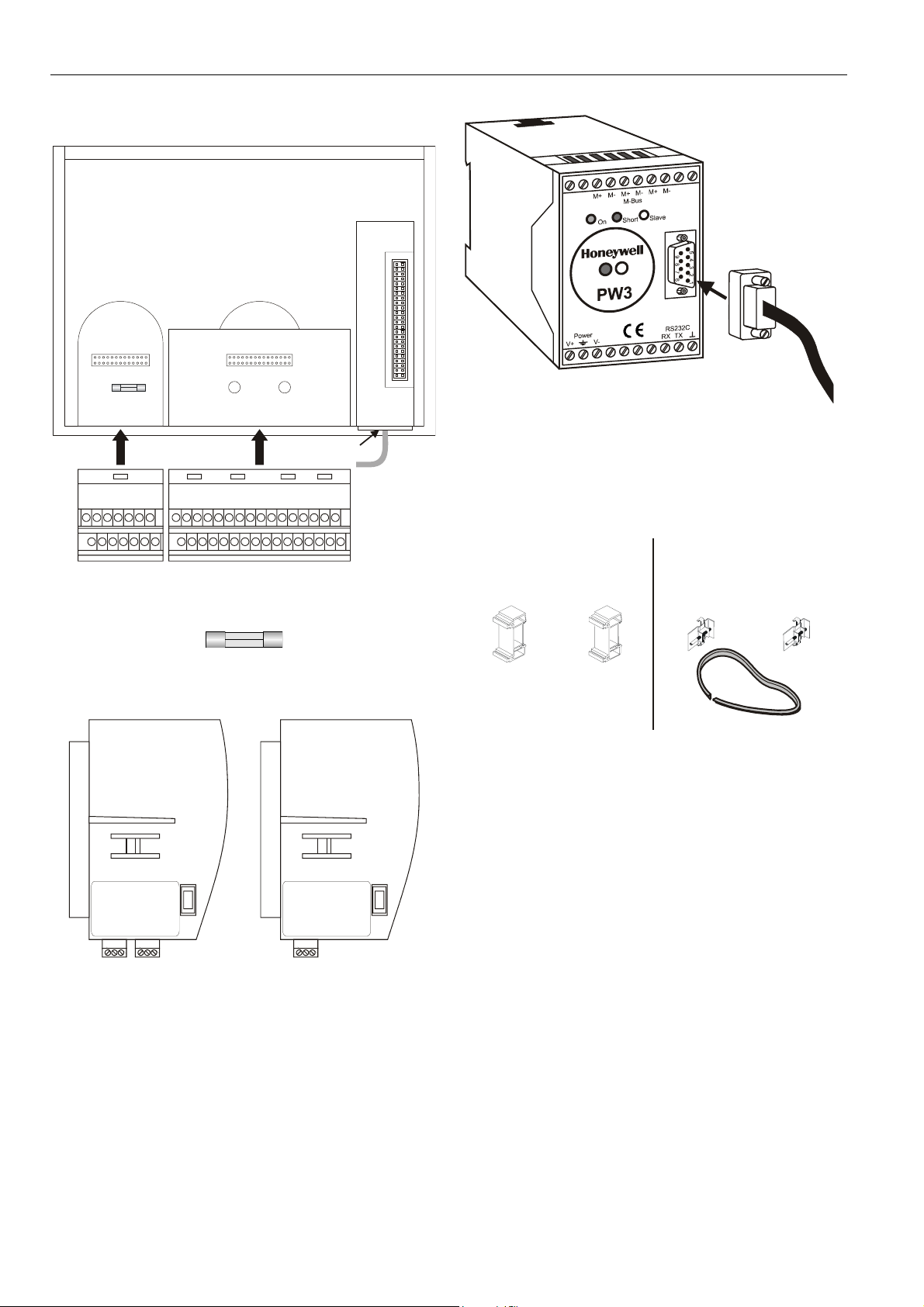
Hardware Overview
port for
application
module
port Bport A
fuse
(4 A, quick-acting)
block A block B
hardware
reset
adjustment
for LCD
serial port
Fig. 1. Excel 50 Controller housing (rear view)
Fig. 2. Fuse, 4 A quick-acting (behind Terminal Block A)
XD50-FLSXD50B-FCL
Fig. 3. Application modules (examples)
XW586
Fig. 4. Meter-Bus adapter
NOTE: The PW3 (or PW20) M-Bus adapter and XW586 M-
Bus adapter cable are optional accessories which
must be ordered separately.
XL50ACC2
(incl. in delivery)
DIN rail mounting clips
front-door mounting clamps
XL50-ACC3
(ordered separately)
sealing
Fig. 5. Mounting accessories
Version Overview
Housing:
With Man-Machine-Interface (MMI)
Without MMI
Application Modules:
See Table 22.
Mounting:
In cut-out of front door (requires ordering XL50-ACC3)
Inside cabinet, front facing DIN rail
Terminals:
Screw terminal blocks A + B (XS50, incl. in delivery)
EN1B-0101GE51 R0909G 8
Page 9
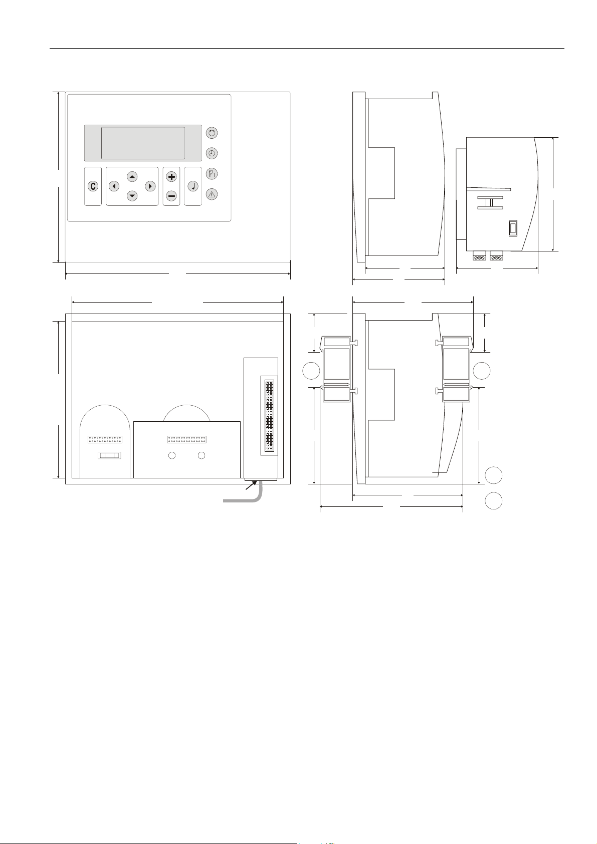
Dimensions
EXCEL 50 INSTALLATION INSTRUCTIONS
100
198
cut-out: 186
port for
application
module
70
81
106
34 34
72
1 2
cut-out: 138 150
fuse
hardware
reset
port Bport A
adjustment
for LCD
serial port
85 85
Fig. 6. Dimensions
126
97
DIN rail clip position
for models without MMI
1
DIN rail clip position
for models with MMI
2
EN1B-0101GE51 R0909G
9
Page 10

EXCEL 50 INSTALLATION INSTRUCTIONS
MOUNTING
With MMI
Controllers with an MMI can be mounted either
• in the cut-out of the front door of a cabinet (the cor-
responding mounting kit consisting of a rubber sealing ring
and front door mounting clamps is not part of the delivery
and must be ordered separately; order no.: XL50-ACC3)
or
• inside the cabinet on a DIN rail with the back facing
towards the DIN rail (the set of DIN rail mounting clips is
included in delivery; order no.: XL50ACC2.)
Without MMI
Controllers without an MMI are mounted inside the cabinet on
a DIN rail with the front facing towards the DIN rail (the set of
DIN rail mounting clips is included in delivery; order no.:
XL50ACC2.)
Table 1. Mounting versions
version mounting accessory
with MMI in cut-out of front door XL50-ACC3 (not. incl.)
with MMI on DIN rail in cabinet XL50ACC2 (incl.)
without MMI on DIN rail in cabinet XL50ACC2 (incl.)
Front Door Mounting (with MMI)
1. Choose the position of the controller in the front door.
Observe the min. and max. distances to other devices in
the front door.
2. Cut a rectangle measuring 7-21/64 in. x 5-7/16 in.
(186 mm x 138 mm) out of the front door (standard DIN
cutout).
Fig. 8. Inserting sealing ring
4. Insert the controller into the cutout in the front door.
Fig. 7. Front door cutout dimensions
3. Insert the rubber sealing ring into the gap around the
front plate of the Excel 50 Controller.
EN1B-0101GE51 R0909G 10
Fig. 9. Inserting controller in front door cutout
5. Attach Front Door Mounting clamps on both sides of the
controller and tighten the screws with a screwdriver as
shown in Fig. 10.
Page 11

EXCEL 50 INSTALLATION INSTRUCTIONS
Inside Cabinet Mounting (without MMI)
1. Break plastic tabs covering the slots on the controller for
the DIN rail mounting clips using a screwdriver.
2. Attach the DIN rail mounting clips to the housing as
shown in Fig. 11.
3. Mount the controller on the DIN rail as shown in Fig. 11.
Fig. 10. Fixing controller with front door mounting
clamps
Fig. 11. Cabinet mounting without MMI
EN1B-0101GE51 R0909G
11
Page 12

EXCEL 50 INSTALLATION INSTRUCTIONS
Inside Cabinet Mounting (with MMI)
The screw terminal blocks and the switch for the bus termination cannot be accessed after the controller with MMI is
mounted on the DIN rail.
Although the bus terminal socket can still be plugged in and
unplugged, it is easier to do the complete installation before
mounting the controller on the DIN rail:
1. Plug in the application module as shown in Fig. 12.
2. Read the complete chapter "Installation" carefully.
3. Follow the instructions in section "Screw Terminal Block
Installation Procedure".
4. Optional: Connect the C-Bus to the application module
as described in section "C-Bus Connection Procedure"
and/or connect the application module serial port to the
Meter-Bus adapter as described in section “Meter-Bus
Connection Procedure”.
5. Break plastic tabs covering the slots on the controller for
the DIN rail mounting clips using a screwdriver.
6. Attach the DIN rail mounting clips at the housing as
shown in Fig. 13.
7. Mount the controller on the DIN rail.
Application Module
CAUTION
Always insert the application module before
connecting the power supply.
CAUTION
Always disconnect the power supply before
unplugging the application module.
— Plug in the application module until it snaps into the
controller housing.
Fig. 12. Cabinet mounting with MMI
Fig. 13. Inserting application module
NOTE: If the application module has been replaced or
removed and re-inserted, please push the reset
button (behind I/O terminals) after power on.
EN1B-0101GE51 R0909G 12
Page 13

EXCEL 50 INSTALLATION INSTRUCTIONS
A
ELECTRICAL CONNECTIONS
When connecting the controller, both VDE, National Electric
Code NEC (or equivalent) and any local regulations concerning grounding and zero voltage must be observed.
Electrical work should be carried out by a qualified electrician.
The electrical connections must be made at the terminal
blocks. Maximum torque for fastening the wiring terminal
screws is 0.5 Nm (4.5 lb-in).
Direct wiring of the Excel 50 is performed using screw
terminal blocks included in the delivery. For proper
installation, follow these instructions. Read all of section
"Electrical Connections" carefully.
SCREW TERMINAL BLOCKS
Terminal Details
Block A
24 Vac24 Vac
24 Vac24 Vac
3 5 7
1
42
DO1 DO2 DO3 DO4 DO5 DO6
15 33
19
2117
16 34
AO1 AI1AO2 AI2AO3
AO4 AI4DI1
Fig. 15. Screw Terminal Blocks A and B
NOTE: The output (18...30 Vdc) of terminal 32 in screw
terminal block B is not stabilized. If you wish to
connect terminal 32 to a digital input via a potentialfree relay, see Fig. 24 on page 20.
9 11
1086
12
26
DI2
13
14
Block B
35
28 4630 32 48
31, 30 = +10 V / 5 mA REF.
32, 30 = DI-POWER
GNDGND
37 39234125 43274529 31
4020 3818 36
4424 4222
AI3
AI5
AI6DI3
47
AI8
AI7DI4
BLOCK A
BLOCK B
Fig. 14. Wiring options
The two screw terminal blocks A and B (order no.: XS50) are
attached directly to the controller housing.
Table 2. Terminal blocks
name code no. of terminals
screw terminal block
XS50 Block A 14
XS50 Block B 34
Cabling
Cable Routing
All signal (input/output, low voltage) cables are communication circuits in accordance with VDE 0100, VDE 0800 and
local regulations and should therefore be routed separately
from line voltage. All circuits are power-limited.
Table 3. Min. distances to line voltage
cable type min. distance
unshielded cable 4 in. (100 mm)
shielded cable 3/8 in. (10 mm)
IMPORTANT
Avoid joining sensor cables.
EN1B-0101GE51 R0909G
13
Page 14

EXCEL 50 INSTALLATION INSTRUCTIONS
Shielding
sensor
Fig. 16. Sensor shielding
Shielding of sensor and actuator cables with low protective
voltages is not necessary if the general guidelines on cable
routing are observed (see section "Cable Routing", page 13).
If these guidelines cannot be observed, shielded cable must
always be used. The shielded cable must be grounded as
shown in Fig. 16.
IMPORTANT
Shielding of I/O cables that are connected to
peripherals such as sensors and actuators must be
grounded at the control cabinet side, only; this is in
order to avoid ground loops.
All Honeywell actuators are RFI suppressed in accordance
with VDE 0871/B and VDE 0875/N.
Lightning Protection
Please check with your local Honeywell representative for
information on lightning protection.
NOTE: Use Honeywell surge protectors or Honeywell-
approved third-party surge protectors.
Cable Lengths and Cross Sectional Areas
Table 4. Signal types and cross-sectional areas
cross-sectional area
type of signal
Power supply
(24 Vac)
Low-current
signals*
*E.g. for 0...10 V sensors, totalizers, digital inputs, 0...10 V
signals for actuators.
≤ 300 ft
(100 m)
≤ 16 AWG
(≥ 1.5 mm
≤ 550 ft
(170 m)
≤ 14 AWG
2
)
(≥ 2.5 mm2)
≤ 20 AWG (≥ 0.5 mm
≤ 1,300 ft
(400 m)
-
2
)
IMPORTANT
The max. length of a signal cable with 24 Vac supply
is 550 ft (170 m). The max. length of a two-wire,
0...10 Vdc signal cable is 1,300 ft (400 m). The
secondary side of the transformer must not be
connected to earth ground.
max. 170 m
min. 2.5 mm
PRIMARY
VOLTAGE
TRANSFORMER
1
2
GND
24 Vac
Y (0...10 Vdc)
2
GND
24 Vac
Fig. 17. Power for Excel 50 with 24 V actuator (single
transformer)
If the distance between the controller and actuator or sensor
with 24 Vac supply is greater than 550 ft (170 m), a separate
external transformer for the actuator or sensor is necessary.
max. 400 m
2
GND
24 Vac
GND
TRANSFORMER
PRIMARY
VOLTAGE
TRANSFORMER
GND
24 Vac
min. 0.5 mm
1
2
Y (0...10 Vdc)
Fig. 18. Power for Excel 50 with 24 V actuator (separate
transformers)
IMPORTANT
We recommend installing a fuse on the secondary
side of the transformer in order to protect the devices
against miswiring.
PRIMARY
VOLTAGE
EN1B-0101GE51 R0909G 14
Page 15

EXCEL 50 INSTALLATION INSTRUCTIONS
Analog Inputs
Technical Description
The analog inputs convert data from passive sensors and
active sensors with voltage output. The analog inputs can be
used as current inputs for active sensors, but then an external
resistor parallel to the sensor is necessary. It is also possible
to feed digital signals to the analog inputs (see also section
"Sensors and Transducers" on page 18).
Technical Specification
Number: Eight analog inputs
Types of input signals:
NTC 20 kΩ
0 to +10 V (max. +11 V)
0 (4) to 20 mA (with an external resistor of 499 Ω ±0.25%
[see Fig. 19])
Each input is switched automatically via software either as
input for NTC 20 kΩ (low impedance) or voltage source
0...+10V (max. +11 V, high impedance).
NTC 20kΩ: Range = -58 … +302 °F (-50 … +150 °C)
Voltage source: Range = 0...10 V
IMPORTANT
The analog inputs are protected against short circuit
and overvoltage up to 24 Vac and 40 Vdc. If any
input is sourced with more than 40 Vdc or negative
voltage, the other inputs will be influenced. This
could result in wrong values.
4 33
3
2
SAF25
10 33
11
12
VMP
TRANSFORMER FOR
ACTIVE SENSOR
0 - 5 V
I = 1 mA
0 - 10 V
I = 1 mA
A
34
31
34
31
SENSOR
NTC 20 k
B
ACTIVE
SENSOR
0-10V
C
0(4) to
20 mA
1
2
AI1
AI2
AI3
AI4
AI5
AI6
AI7
R1
AI8
499
0.25%
32
34
36
38
40
42
44
46
48
31
33
35
37
39
41
43
45
47
10 Vdc
max. 5 mA
AGND
Analog Inputs Used as Digital Inputs (O.S. 2.03.xx or
lower)
10 Vdc
31
max. 10 mA
32
33
34
35
36
37
38
39
40
42
44
46
48
AGND
41
43
45
47
NOT CONNECTED
NORMALLY CLOSED
230 Vac/ 50 Hz
120 Vac/ 60 Hz
NORMALLY OPEN
NOT CONNECTED
NORMALLY OPEN
230 Vac/ 50 Hz
120 Vac/ 60 Hz
L
N
L
N
AI1
AI2
AI3
AI4
AI5
AI6
AI7
AI8
Fig. 20. Analog inputs used as digital inputs
For normally-open contacts, a digital signal must be switched
via the changeover contact of an additional relay.
Unconnected analog inputs have a default voltage of 8.5 V.
This is interpreted by the controller as a logical 1. This means
that, in general, no external relay is needed for normally-open
contacts.
IMPORTANT
The relay contact must be suitable for switching low
voltage. In the case of long cable distances, the
00000061
analog input signal may be sensitive to interference.
In this case, an external relay may also be used for
normally-closed contacts.
0000062a
Fig. 19. Analog inputs, sensor connections
EN1B-0101GE51 R0909G
15
Page 16
EXCEL 50 INSTALLATION INSTRUCTIONS
Analog Inputs Used as Digital Inputs (O.S. 2.04.xx or
higher)
10 Vdc
31
max. 5 mA
32
33
34
35
36
37
38
39
40
42
44
46
48
AGND
41
43
45
47
NOT CONNECTED
NORMALLY OPEN
230 Vac/ 50 Hz
120 Vac/ 60 Hz
NOT CONNECTED
NORMALLY CLOSED
230 Vac/ 50 Hz
120 Vac/ 60 Hz
L
N
POWER
10 Vac
L
N
AI1
AI2
AI3
AI4
31
31
AI6
AI7
AI8
Fig. 21. Analog inputs used as digital inputs
Unconnected inputs have a default voltage of 0 V.
Table 5. Accuracy of analog inputs with NTC sensors
0000062m
range
deviation / ± Kelvin
(without sensor tolerance)
NTC (20 kΩ)
-58...-40°F (-50...-40°C) ≤ 5.5 K
-40...-22°F (-40...-30°C) ≤ 3.0 K
-32...-4°F (-30...-20°C) ≤ 1.8 K
-4...14°F (-20...-10°C) ≤ 1.1 K
14...32°F (-10...0°C) ≤ 0.8 K
32...50°F (0...10°C) ≤ 0.6 K
50...122°F (10...50°C) ≤ 0.4 K
122...158°F (50...70°C) ≤ 0.6 K
158...194°F (70...90°C) ≤ 1.0 K
194...212°F (90...100°C) ≤ 1.5 K
212...248°F (100...120°C) ≤ 2.4 K
248...302°F (120…150°C) ≤ 5.3 K
EN1B-0101GE51 R0909G 16
Page 17

Pull-Up Resistor Handling
EXCEL 50 INSTALLATION INSTRUCTIONS
10 V
Case 1 Case 2 Case 3
24.9 k
Ω
(pull-up)
A
150 k
Ω
49.9 k
D
Ω
10 V
24.9 k
(pull-up)
150 k
Ω
A
Ω
49.9 k
D
Ω
5 V
18.2 k
(pull-up)
100 k
Ω
A
Ω
100 k
D
Ω
Fig. 22. Input circuit diagram
Table 6. Pull-up resistor handling
pull-up load-free voltage
device
voltage hardware
de-
activated
by @(8
XF521,
XF521A
XF526 fixed NO
10 V
XFL521,
XFL521A/B
Smart I/O
XFC
5 V
fixed NO YES case 2 8.89 V
optional
switch-off
YES
YES
configured
by DIP
switch
(3
config.(6 case 1
(4
NO
configured
by plug-in
NO
YES
input
activated
for DI on AI
circuit
diagram
(Fig. 22)
YES case 2 8.89 V
with NTC
or low-
impedance
input
8.89 V
YES(7 case 3 5 V
for voltage
input or
high-
impedance
input
0 V
XL20 fixed NO YES case 2 8.89 V
XL25A /
XL50A
XL100,
10 V
XL100A
XL100B
XL100C
(1
controller firmware ≥ 2.03;
(2
controller firmware ≥ 2.02;
(3
controller firmware ≥ 2.03 (local/shared mode), CARE ≥ 5.00.01 (open mode);
(4
CARE ≥ 5.00.01;
(5
controller firmware < 2.04;
(6
controller firmware < 2.04 (local/shared mode), CARE ≥ 5.01.xx (open mode);
(7
CARE ≥ 5.01.xx;
(8
Assigning "@" as first digit of input characteristic name (e.g.: "@0-10V") in CARE text editor disables the pull-up resistor.
optional
switch-off
fixed
optional
switch-off
(2
YES
YES(5 case 1 0 V
NO
YES configurable
YES(1 NO
NO
YES case 2 8.89 V
YES(5
case 1
8.89 V
0 V
EN1B-0101GE51 R0909G
17
Page 18

EXCEL 50 INSTALLATION INSTRUCTIONS
Sensors and Transducers
Table 7. Sensors suitable for use with Excel 50 (external transducer not required)
sensor type range
AF20 Outside Air Temperature Sensor -20…+30° C
VF20A Strap-On Temperature Sensor 0…+110° C
KTF20 Boiler Temperature Sensor 0…+100° C
LF20 Duct Temperature Sensor -30…+100° C
AQS51 or C7110C1001 CO2 Sensor 0...2000 ppm CO2 0…10 V = 0..2000 ppm
C7110A1005 Air Quality (Mixed Gas) Sensor 0…100% 0…10 V = 0…100%
T7560C1006 Combined Room Temp. / Humidity Sensor
or H7012B1023 Room Humidity Sensor
Table 8. Room Temperature Sensors suitable for use with Excel 50 (external transducer not required)
sensor type range
T7460A1001 Room Temperature Sensor
T7460B1009 Room Temperature Sensor
TF22 Room Temperature Sensor
T7460C1007 Room Temperature Sensor
T7460E1002 Room Temperature Sensor
T7460F1000 Room Temperature Sensor
T7460A1000 Room Temperature Sensor
Sensor
C7110D1009 Combined Room Temperature / Humidity
Sensor
T7560B1008 Combined Room Temperature / Humidity
Sensor
*supported in AH03
6…40°C NTC
20...95% relative humidity 0..10 V = 0...100%
6...40°C NTC
setpoint wheel linear input
6...40°C NTC
setpoint wheel linear input
6…40°C NTC
setpoint wheel linear input
operating knob -
6...40°C NTC
setpoint wheel linear input
occupancy button* -
6...40°C NTC
setpoint wheel linear input
occupancy button*
fan speed, 3 stages
6...40°C NTC
setpoint wheel linear input
occupancy button*
fan speed, 5 stages
6...40°C NTC
setpoint wheel linear input
occupancy button*
fan speed, 5 stages
6…40°C NTC T7460C1006 Combined Room Temperature / Humidity
20...95% r.h. 0..10 V = 0…100%
6..40°C NTC
0...2000 ppm CO2 0..10 V = 0…2000 ppm
setpoint wheel linear input
occupancy button* -
6...40°C NTC
20...95% r.h. 0...10 V = 0...100%
setpoint wheel linear input
occupancy button*
fan speed, 5 stages
characteristic in controller
(set using CARE)
NTC
characteristic in controller
(set using CARE)
-
-
-
-
EN1B-0101GE51 R0909G 18
Page 19
EXCEL 50 INSTALLATION INSTRUCTIONS
Table 9. Humidity Sensor suitable for use with Excel 50 (external transducer not required)
sensor type
H7015B1020 Duct Humidity Sensor
H7508A1042 Outside Humidity Sensor
Table 10. Flue Gas Sensors suitable for use with Excel 50 (external transducer required)
sensor type
AGF1 0...10 V = 0…400 °C
Table 11. Differential (+ Static Duct) Pressure Sensor suitable for use with Excel 50 (no external transducer required)
sensor type range
Pressure Sensor
Table 12. Differential Pipe Pressure Sensors suitable for use with Excel 50 (external transducer not required)
sensor type range
FHBN 3+ED1 0 – 2.5 bar 0...10 V = 0...250 kPa
FHBN 5 +ED1 0 – 5 bar 0...10 V = 0...500 kPa
FHBN 10 +ED1 0 – 10 bar 0...10 V = 0...1000 kPa
characteristic in controller
(set using CARE)
0...500 Pa 0..10 V = 0...500 Pa set jumper to 0...500 Pa DPT500 Differential (+ Static Duct)
0... 1000 Pa 0..10 V = 0...1000 Pa set jumper to 0...1000 Pa
Digital Inputs
Technical Description
V
10
5
2.5
0
1
0
Fig. 23. Input switching voltages
The digital input signals can be DC voltage signals. If an input
voltage is higher than 5 V, the digital signal switches to logic
"1" status. With a hysteresis of 2.5 V, the input signal must fall
below 2.5 V before the digital status switches to logic "0".
Three out of four digital inputs can be used as totalizers.
With V2.04.00 and higher firmware, the online point attribute
"Normally Open / Normally Closed" (NO/NC) defines the
relation between the physical state (open/closed) and its
logical status. See Table 13.
t
t
characteristic in controller
(set using CARE)
0..10 V = 0...100% set jumper to 0...10 V
requires LC-MV-1xPT1000.0-400°C: converts
PT1000 to 0…10 V: order from: www.rinckelectronic.de
characteristic in controller
(set using CARE)
characteristic in controller
(set using CARE)
additional remarks
additional remarks
additional remarks
additional remarks
ED1 is an integrated transducer
with 0…10 V output
Technical Specification
Number: 4 digital inputs
Type of signals: DC signal (max. 24 Vdc)
Input resistance: 10k Ω
IMPORTANT
The digital inputs are protected against short circuit
and overvoltage up to 24 Vac and 40 Vdc.
Parameter Requirements:
If the digital inputs are used for normal digital or analog
signals, the signals must meet the static and dynamic
requirements stated in Table 13 and Table 14.
If three out of four digital inputs are used as totalizers, the
signals at the totalizer inputs must fulfill the static and
dynamic requirements stated in Table 13 and Table 15 while
the signal at the fourth input must meet only the static requirements of Table 13.
Table 13. Static parameters of digital inputs
contact
position
open NO 0
closed NO 1
open NC 1
closed NC 0
NO/NC
attribute
logical status input voltage
≤ 2.5 V
≥ 5 V
≤ 2.5 V
≥ 5 V
EN1B-0101GE51 R0909G
19
Page 20
EXCEL 50 INSTALLATION INSTRUCTIONS
Table 14. Dynamic parameters of digital inputs
frequency
max. 0.4 Hz min. 1.25 s min. 1.25 s max. 50 ms
Table 15. Dynamic parameters of totalizers
frequency
max. 15 Hz min. 20 ms min. 30 ms max. 5 ms
pulse
duration
pulse
duration
pause
interval
pause
interval
bounce time
bounce time
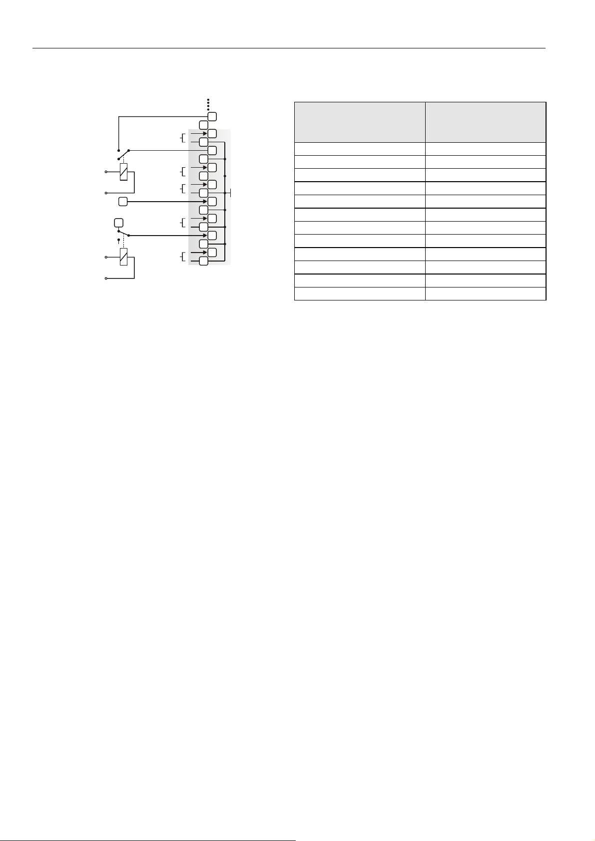
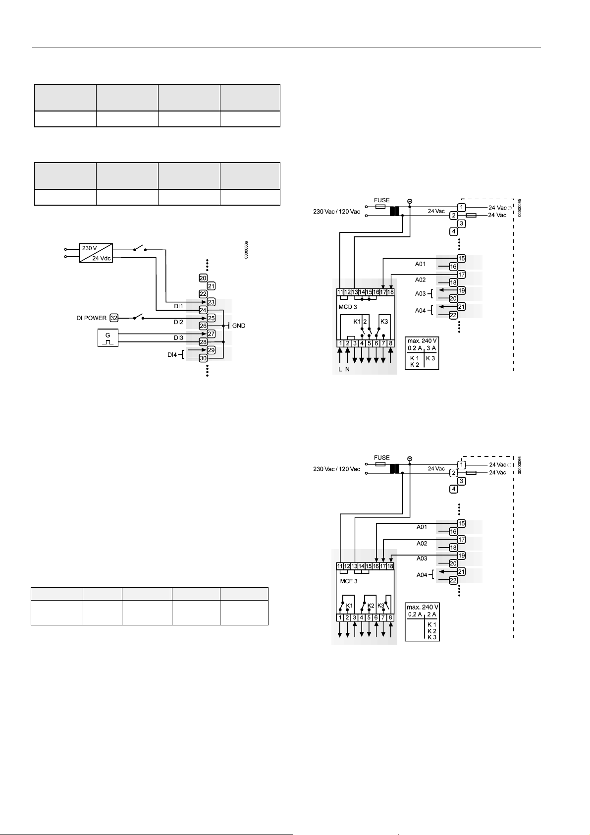
Connection Examples
IMPORTANT
The external supply of the relay modules must be
24 Vac, the same as of the supply of the controllers.
The analog outputs are protected against overvoltage
up to 24 Vac and 35 Vdc.
Supply:
Several relay modules can be connected in series via the
bridged terminal pair:
24 Vac: Terminals 11/12 of the relay
24 Vac (-): Terminals 13 to 16 of the relay
Fig. 24. Digital inputs, connection examples
Analog Outputs
Technical Description
Analog outputs can be used, for example, to operate valve or
damper actuators. The characteristic curves for these
actuators can be defined via MMI. These outputs are
programmable.
Each analog output can also be used as a digital output.
Technical Specification
Number: Four analog outputs
Analog output details:
Table 16. Technical specifications of analog outputs
voltage current resolution min. step accuracy
0...10 V,
max. 11 V
Relay Modules
The relay modules facilitate the control of peripheral devices
with high load via the analog outputs of the controller. The
connection examples (for the relay modules MCD 3 and
MCE 3) are shown here. These outputs are programmable.
max.
1 mA
8-Bit 0.043 mV
±100 mV
±1 digit
Fig. 25. Analog outputs, connection of relay MCD 3
MCD 3:
Relay terminal 17 controls the changeover contact K3.
Relay terminal 18 controls the ON contacts K1, K2.
Ground can be looped through terminals 2/3.
Fig. 26. Analog outputs, connection of relay MCE 3
MCE 3:
Relay terminal 16 controls the ON contact K3.
Relay terminal 17 controls the changeover contact K2.
Relay terminal 18 controls the changeover contact K1.
EN1B-0101GE51 R0909G 20
Page 21
EXCEL 50 INSTALLATION INSTRUCTIONS
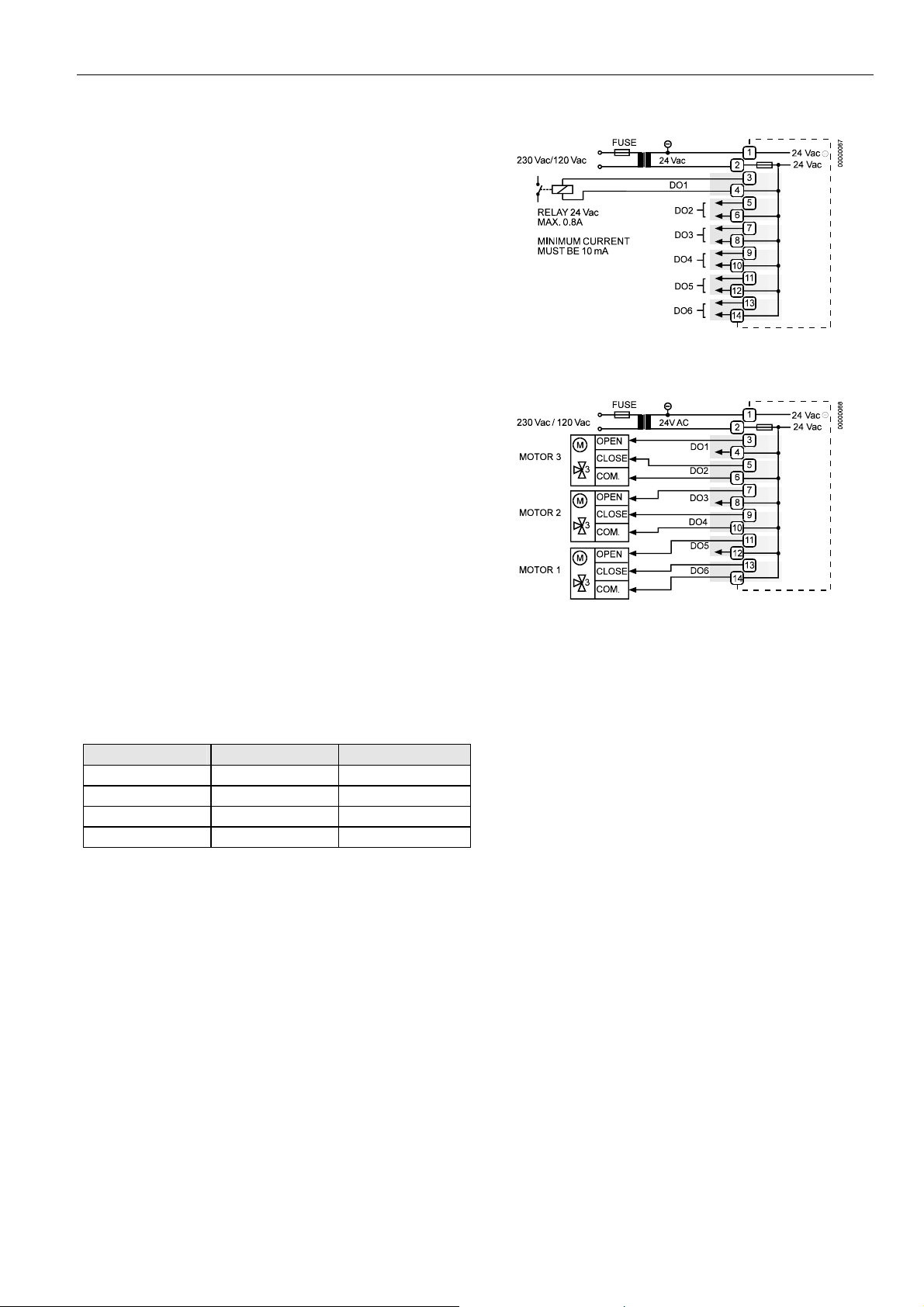
Digital Outputs
Technical Description
The digital outputs are switched by a triac that can be
connected directly to an external relay. These outputs are
programmable.
Technical Specification
Number: Six digital outputs
Output stages:
Low signal 0 V
High signal 24 Vac
Type Close, only
Load:
Per output min. 0.01 A
max. 0.8 A
Total max. 2.4 A
Cos ϕ 0.5 to 1
IMPORTANT
The digital outputs are protected against short circuit
current via internal fuse, but they are not protected
against overload. All digital outputs are protected via
only a single fuse; if any digital output is shortcircuited, the fuse will be blown and will interrupt the
main power. In that case, the controller does not
work. If the CPU is running into the WATCHDOG as
a result of a software or hardware error, all digital
outputs will be set to low signal, which means all
digital outputs are inactive.
Beginning with V2.04.00 firmware, the online point attribute
"Normally Open / Normally Closed" (NO/NC) defines the
relation between the physical state (relay ON/OFF) and its
logical status. See Table 17.
Table 17. Digital output parameters
relay ON/OFF NO/NC attribute logical status
ON NO 1
OFF NO 0
ON NC 0
OFF NC 1
Connection Examples
Fig. 27. Digital outputs, connection of relay
Fig. 28. Digital outputs, direct connection of 3-position
actuators
Power Supply
The Excel 50 Controller is powered by an external transformer.
Transformer requirements for one Excel 50 Controller:
Voltage 24 Vac ±20%
Current 3 A, if fully equipped (6 DO's x 0.4 A)
2 A, if current of DO's does not exceed 1.8 A
Power 72 VA, if fully equipped
The transformer, already installed in the cabinet, can be used
to supply several controllers, communication devices or peripherals (actuators, etc.) if the transformer provides sufficient
power.
EN1B-0101GE51 R0909G
21
Page 22
EXCEL 50 INSTALLATION INSTRUCTIONS
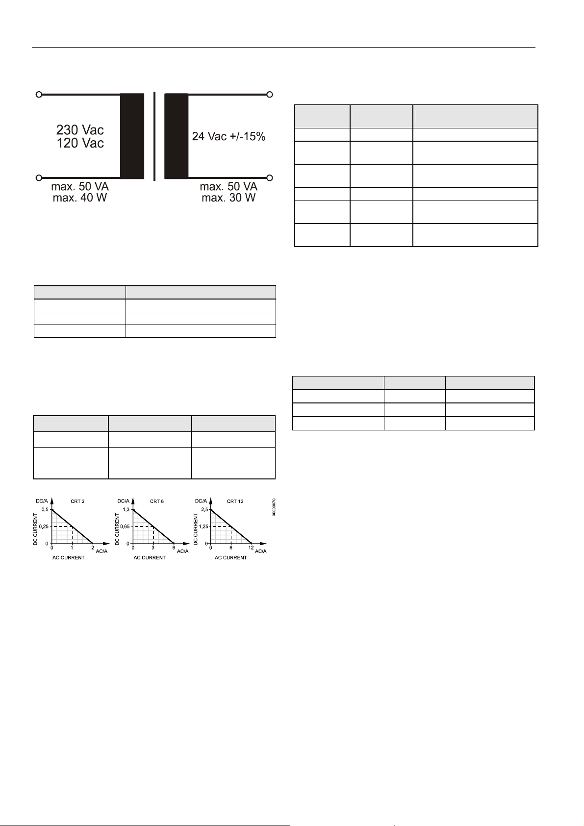
PRIMARY VOLTAGE SECONDARY VOLTAGE
Fig. 29. Transformer example
CRT-Series
Table 18. No. of controllers connected to one transformer
transformer Excel 50 controller
CRT 2 1 (1.8 A max.)
CRT 6 2
CRT 12 4
Use quick-acting backup fuse 10 A (or automatic H16 or L16)
to protect the transformer primary side. On the primary side of
the CRT 2, there is a fusible output of type M 0.315 A (T)
250 V for the purpose of fine fusing.
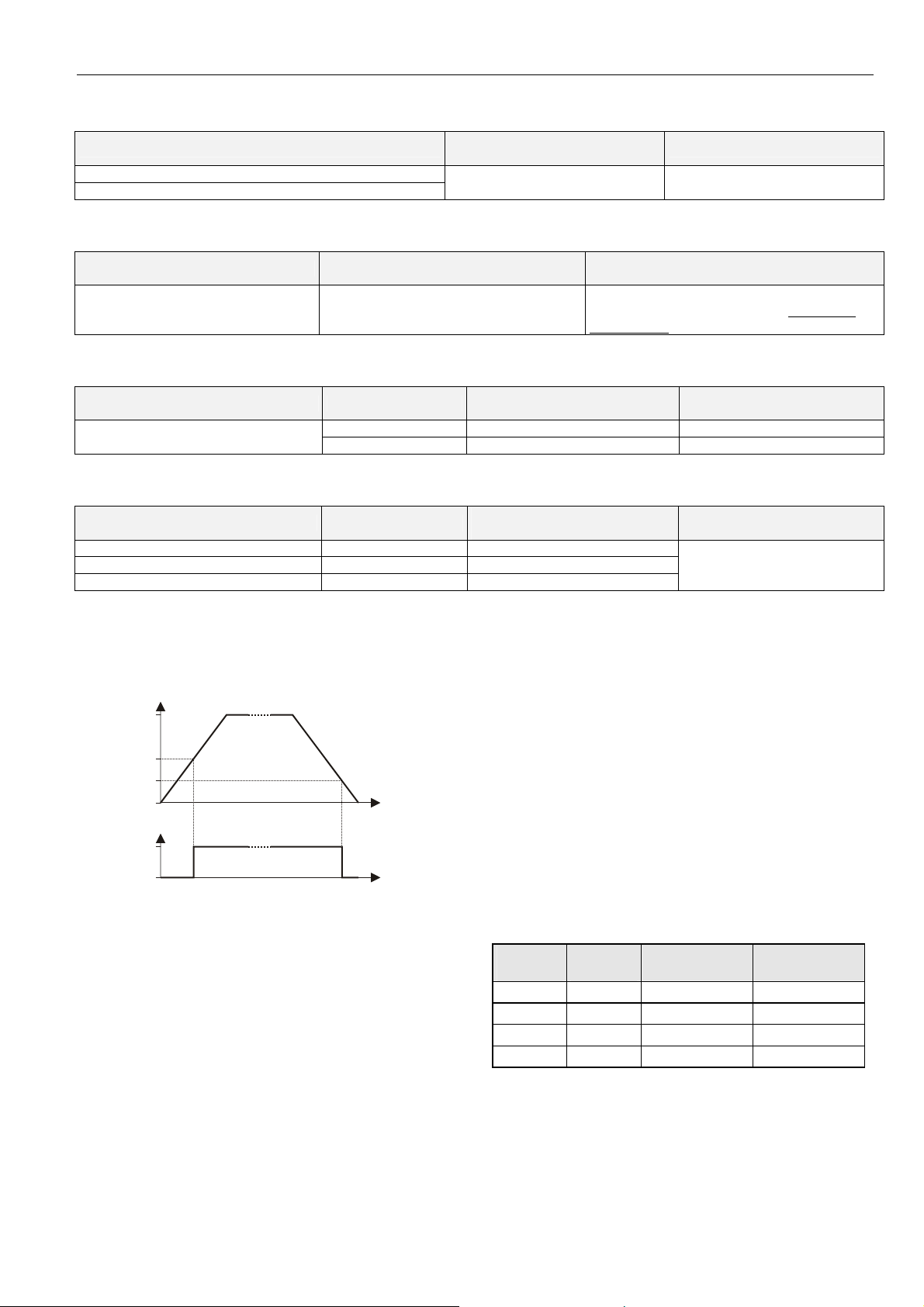
Table 19. Overview of CRT Series AC/DC current
transformer max. AC current max. DC current
CRT 2 2 A 0.5 A = 500 mA
CRT 6 6 A 1.3 A = 1300 mA
CRT 12 12 A 2.5 A = 2500 mA
Fig. 30. AC/DC current graphs
1450 Series
Table 20. 1450 Series transformers
part #
1450 7287
-001 120 Vac 24 Vac, 50 VA
-002 120 Vac
-003 120 Vac
-004 240/220 Vac 24 Vac, 50 VA
-005 240/220 Vac
-006 240/220 Vac
All transformers of the 1450 series are designed for 50/60 Hz
AC and have insulated accessory outputs. The transformers
include built-in fuses, line transient/surge protection and AC
convenience outlets and meet NEC class 2 requirements.
primary side secondary side
2 x 24 Vac, 40 VA and 100 VA
from separate transformer
24 Vac, 100 VA and 24 Vdc
600 mA
2 x 24 Vac, 40 VA and 100 VA
from separate transformer
24 Vac, 100 VA and 24 Vdc,
600 mA
Standard Transformers
Standard commercially available transformers must fulfill the
following specifications:
Table 21. Requirements for standard transformers
output voltage impedance AC current
24.5 Vac to 25.5 Vac
24.5 Vac to 25.5 Vac
24.5 Vac to 25.5 Vac
≤ 1.15 Ω
≤ 0.40 Ω
≤ 0.17 Ω
max. 2 A
max. 6 A
max. 12 A
Screw Terminal Block Installation
1. Make sure that the power supply of the cabinet is
disconnected.
2. Make sure that the power supply of the cabinet is
disconnected and that the application module is plugged
in the housing.
3. Choose the min. cross sectional areas for all cables to
and from sensors, actuators, valves, relays, etc. you
want to connect to the Excel 50 Controller from Table 4.
4. Connect sensors, transducers, etc. to the analog input
terminals.
EN1B-0101GE51 R0909G 22
Page 23
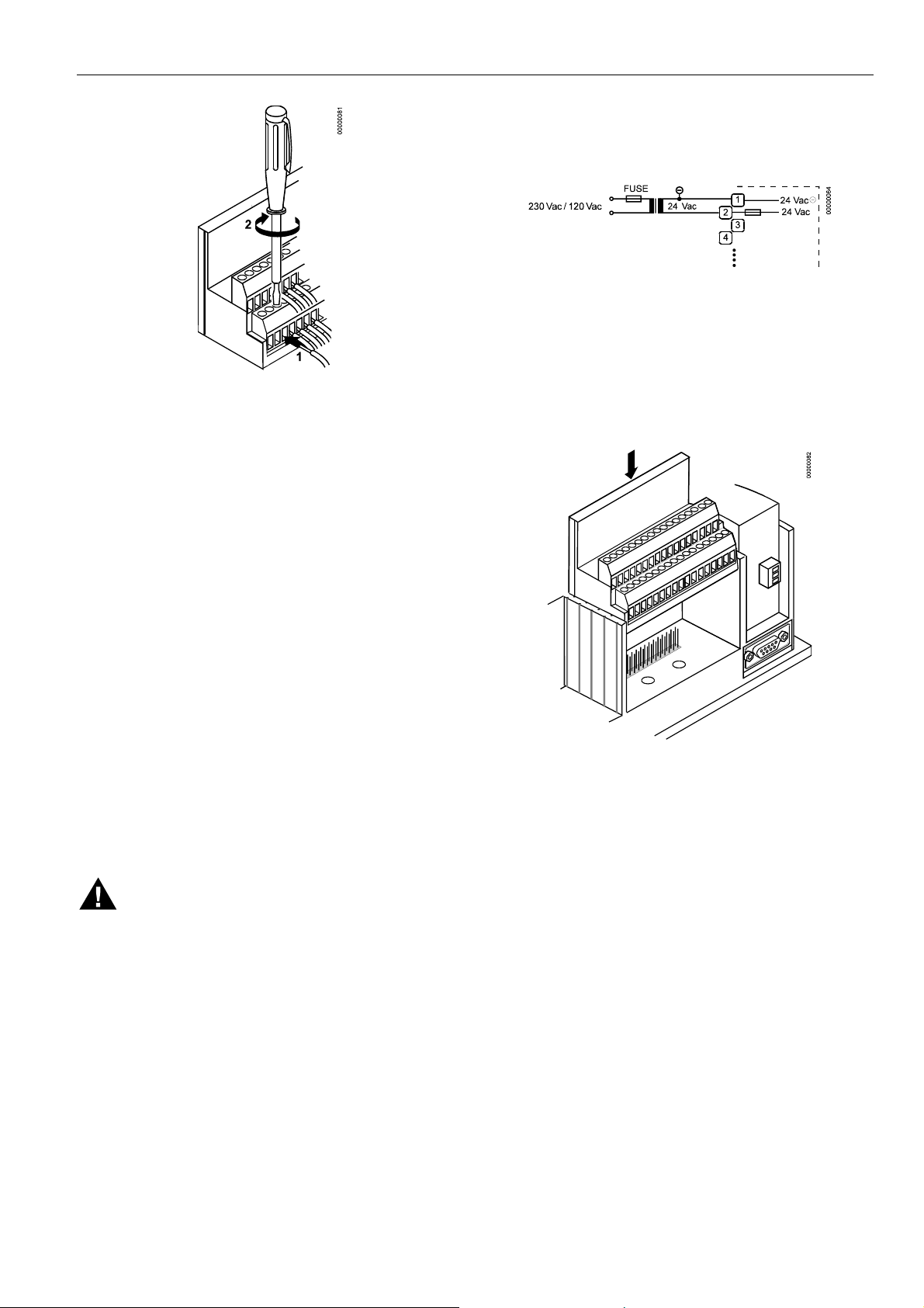
Fig. 31. Connecting a cable to a screw terminal
IMPORTANT
When installing a separate external transformer, do
not connect the cabinet ground to the controller
system ground.
5. If the distance between the controller and an actuator or
sensor with 24 Vac supply is greater than 550 ft
(170 m):
a) Choose a transformer from the transformers listed in
section "
Power Supply".
b) Connect the chosen transformer directly to the
actuator or sensor.
6. Connect sensors, transducers, etc. to the digital input
terminals.
7. Connect valves, actuators, relays, etc. to the analog
output terminals.
8. Connect relays, actuators etc. to the digital output
terminals.
9. Select one of the transformers of the CRT series or
1450 series (Table 19 or Table 20) or use a commercially available standard transformer fulfilling the
requirements in Table 21.
10. Make sure that the application module is plugged into
the controller housing.
EXCEL 50 INSTALLATION INSTRUCTIONS
11. Connect the 24 Vac (-) on the secondary side of the
transformer to terminal 1 on Screw Terminal block A.
12. Connect the 24 Vac on the secondary side of the
transformer to terminal 2 on Screw Terminal block A.
Fig. 32. Connecting the power supply
IMPORTANT
If there already are additional transformers, for
example supplying actuators or active sensors:
— Connect the 24 Vac (-) (secondary side) of the
transformers together.
13. Attach the terminal blocks to the housing as shown in
Fig. 33.
Fig. 33. Attaching of screw terminal blocks
WARNING
High Voltage
Risk of death or electrical shock.
— Do not connect line power supply directly to the
terminals.
— Insulate devices with 120 Vac / 230 Vac by a
transformer.
IMPORTANT
The transformer feeding the Excel 50 Controller must
be in the same cabinet. If field devices with DC load
are used, when selecting the transformer, the max.
DC current must be considered.
The secondary side of the transformer must not be
connected to earth ground.
EN1B-0101GE51 R0909G
23
Page 24

EXCEL 50 INSTALLATION INSTRUCTIONS
Adjusting the MMI Display Contrast
Front Door Mounted with MMI
1. Unplug the screw terminal block B to Port B while the
controller is connected to the power supply.
2. Adjust the display contrast with a slotted screwdriver or
a cross-tip screwdriver.
IMPORTANT
Turn the display contrast potentiometer gently. Using
excessive force may damage the potentiometer and
disable the display.
Fig. 34. Adjusting the display contrast
3. Attach screw terminal block B to Port B.
DIN Rail Mounted with MMI
1. Dismount the controller from the DIN rail.
2. Unplug the screw terminal block B to Port B while the
controller is connected to the power supply.
3. Adjust the display contrast with a slotted screwdriver or
a cross-tip screwdriver as shown in Fig. 34.
IMPORTANT
Turn the display contrast potentiometer gently. Using
excessive force may damage the potentiometer and
disable the display.
4. Attach screw terminal block B to Port B.
5. Mount the controller on the DIN rail again.
EN1B-0101GE51 R0909G 24
Page 25
EXCEL 50 INSTALLATION INSTRUCTIONS
COMMUNICATION
The Excel 50 Controller can communicate with the Excel
Building Supervisor (XBS/XBSi, and Enterprise Buildings
Integrator) and other EXCEL 5000 devices via the C-Bus. The
Excel 50 Controller also has the capability to communicate
with devices on a L
cation option is connection to a Meter-Bus. All communications options are dependent upon the application module,
and not all options are available on one module (see Table
22).
A modem/ISDN terminal adapter may be connected to Flash
EPROM versions with V2.01.00 software or newer to allow remote communication with the controller.
Table 22. Application module versions
module description
XD50B-F
XD50B-F-TW Stand-alone; 2 MB Flash EPROM; 256 KB RAM;
XD50B-FC
XD50B-FL
XD50B-FCL
XD50B-FL-TW
XD50B-FCL-TW
XD50-FCS Bus-wide access via C-Bus / Meter-Bus; 1 MB
XD50-FLS Bus-wide access via LONWORKS® / Meter-Bus;
NOTE: Flash EPROM allows easy upgrading of the
operating system by means of direct firmware
download via serial port or C-Bus.
IMPORTANT
Electrostatic discharge can damage the application
module. Always disconnect the power supply when
plugging in and unplugging the application module.
ONWORKS network. A further communi-
Stand-alone; 2 MB Flash EPROM; 256 KB RAM;
European and Chinese language support
Taiwanese language support
Bus-wide access via C-Bus; 2 MB Flash EPROM;
256 KB RAM; European and Chinese language
support
Bus-wide access via L
Flash EPROM; 256 KB RAM; European and
Chinese language support
Bus-wide access via C-Bus /
2 MB Flash EPROM; 256 KB RAM; European
and Chinese language support
Bus-wide access via L
Flash EPROM; 256 KB RAM; Taiwanese
language support
Bus-wide access via C-Bus /
2 MB Flash EPROM; 256 KB RAM; Taiwanese
language support
Flash EPROM; 256 KB RAM
2 MB Flash EPROM; 256 KB RAM
ONWORKS® Bus; 2 MB
LONWORKS® Bus;
ONWORKS® Bus; 2 MB
LONWORKS® Bus;
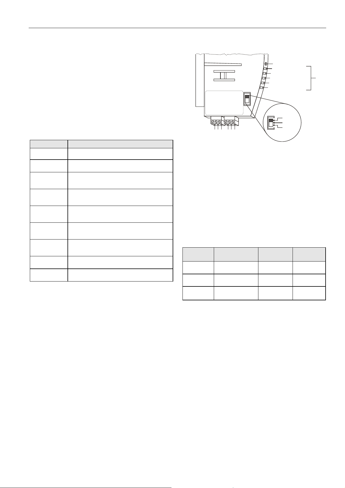
C-Bus
LonWorks service button
POWER, GREEN
LonWorks service LED, RED
C-BUS TxD, YELLOW
C-BUS RxD, YELLOW
RESERVED
XD50B-FCL
C-BUS TERMI-
NATION SWITCH
1 2 3
A1
4 5 6
C-BUSLonWorks BUS
C-
A2
C+
SHIELD
not used
TOP
MIDDLE
BOTTOM
Fig. 35. C-Bus connection and LEDs (example)
Up to 30 controllers can communicate with one another and
the Excel Building Supervisor PC (XBS) via the C-Bus.
Instead of an Excel 500/600 Controller, other C-Buscompatible components can also be connected (Excel IRC
Multicontroller; Excel EMC; Modem Device XM 100A).
C-Bus Termination
C-Bus-capable application modules are equipped with a DIP
switch (see Fig. 35) for the C-Bus to set the bus termination
appropriate for the communication speed.
Table 23. DIP switch settings for C-bus termination
DIP switch
setting
up 9.6 Kbaud -
middle 76.8 Kbaud middle of bus
down 76.8 Kbaud
communication
speed (max.)
controller
location
beginning or
end of bus
compati-
XD505A,
XL20XD
XD508,
XL20XD508
XD508,
XL20XD508
NOTE: Modules listed in "compatibility" column are used in
Excel 20/100B/500/600 Controllers.
NOTE: The controllers with the termination must be switched
ON prior to the controllers in the middle of the C-Bus.
The C-Bus may not work if the controllers with
termination are switched OFF.
Cable Specification
The max. cable length is 4,000 ft (1,200 m). There are
regional differences as to whether shielded or unshielded
cable must/can be used.
LEDs
bility
IMPORTANT
In Europe, only shielded cable is permitted while in
the US, shielded or unshielded cable can be used.
Inside the cabinet: J-Y-(ST)Y 2 x 2 x 0.8
Outside the cabinet: A-Y-(ST) 2 x 2 x 0.8
In principle, data transmitting cables should be shielded in
case of RFI.
EN1B-0101GE51 R0909G
25
Page 26

EXCEL 50 INSTALLATION INSTRUCTIONS
Table 24 summarizes cable types and gives selection
guidance. Note that baud rate and max. bus length are
related to each other.
Table 24. C-Bus cable types
cable type description recommended for
J-Y-(ST)Y
2 x 2 x 0.8
A-Y-(ST)Y
2 x 2 x 0.8
AK 3702
AK 3740A shielded
Belden 9842 twisted pair
Belden 9841 shielded US
AK 3702
AK 3740A shielded
Each end of the shield on the C-Bus should be connected to
the shield terminal of the respective device. Do not connect it
to the cabinet ground or any other ground points.
shielded,
twisted pair
shielded,
twisted pair
unshielded,
twisted pair
unshielded,
twisted pair
Europe
Inside cabinet
Europe
Outside cabinet
US
not approved for Europe
US (low-cost)
not approved for Europe
Europe
US also possible
US
not approved for Europe
US (low-cost)
not approved for Europe
C-Bus Extension by Using Repeaters
The C-Bus length can be extended by using repeaters. Each
repeater extends the bus length by 4,000 ft (1,200 m).
For the US the repeater is available either with or without
housing. In Europe, only the version with housing is allowed.
Table 25. Order no. for repeaters
description US order no. European order no.
without housing 14507324-001 -
with housing 14507324-002 XD 509
C-Bus Connection Procedure
1. Choose a suitable C-Bus cable from Table 24.
IMPORTANT
Make sure that all bus devices connected to the
same C-Bus are set to the same baud rate;
otherwise, proper communication cannot be ensured.
2. Set the DIP switch according to Table 23.
— Use repeaters to extend to the max. C-Bus length
(see section "C-Bus Extension by Using
Repeaters").
It may take up to two minutes to re-initialize the bus when
adding or removing a controller to/from the C-Bus. During this
time, communication on the C-Bus is lost.
LONWORKS Network Interface
Excel 50 Controllers may be equipped with an application
module (see Table 21) containing an FTT-10A Free Topology
Twisted Pair Transceiver which allows communication with
other device on a L
communicate at 78 Kbaud and provide transformer isolation
so that the bus wiring does not have a polarity; that is, it is not
important which of the two bus terminals are connected to
each wire of the twisted pair. See also Fig. 35.
FTT devices can be wired in daisy chain, star, loop or any
combination thereof as long as the max. wire length requirements given below are met. The recommended configuration is a daisy chain with two bus terminations. This
layout allows for max. bus length, and its simple structure
presents the least number of possible problems, particularly
when adding on to an existing bus.
NOTE: A doubly-terminated bus may have stubs of up to
10 ft (3 m) from the bus to each node.
Table 26. Doubly-terminated bus specifications
Belden 85102 2,700 m (8,900 ft)
Belden 8471 2,700 m (8,900 ft)
Level IV, 22 AWG 1,400 m (4,600 ft)
JY (St) Y 2x2x0.8 900 m (3,000 ft)
TIA568A Categ. 5 24AWG, twisted pair 900 m (3,000 ft)
NOTES:
The cable types listed above are as recommended by
Echelon. The cable recommended by Honeywell is the level
IV, 22 AWG, solid core, nonshielded cable. Belden part
numbers are 9H2201504 (plenum) and 9D220150 (nonplenum).
The FTT specification includes two components that must be
met for proper system operation. The distance from each
transceiver to all other transceivers and to the termination
must not exceed the max. node-to-node distance. If multiple
paths exists, the max. total wire length is the total amount of
wire used.
ONWORKS network. FTT-10A transceivers
cable type max. bus length
IMPORTANT
The C-Bus must be connected through the individual
controllers (open ring). Star connection is not permitted because uncontrollable line reflections could
occur.
3. Connect the cable shield to C-Bus terminal 4 (Fig. 35).
4. Connect the C+ cable to C-Bus terminal 5 (Fig. 35).
5. Connect the C- cable to C-Bus terminal 6 (Fig. 35).
6. If the max. C-Bus length for the chosen cable (Table 24)
is exceeded:
EN1B-0101GE51 R0909G 26
Page 27

Table 27. Free topology (singly-terminated) specifications
EXCEL 50 INSTALLATION INSTRUCTIONS
cable type
max. node-tonode distance
max. total wire
length
Belden 85102 1,650 ft (500 m) 1,650 ft (500 m)
Belden 8471 1,300 ft (400 m) 1,650 ft (500 m)
Level IV, 22AWG 1,300 ft (400 m) 1,650 ft (500 m)
JY (St) Y 2x2x0.8 1,050 ft (320 m) 1,650 ft (500 m)
TIA568A Category 5
24AWG, twisted pair
825 ft (250 m) 1,500 ft (450 m)
IMPORTANT
Do not use different wire types or gauges on the
same LONWORKS network segment. The step change
in line impedance characteristics would cause
unpredictable reflections on the network.
NOTE: In the event that the limit on the total wire length is
exceeded, FTT physical layer repeaters (FTT 10A)
can be added to interconnect segments and increase
the overall length by an amount equal to the original
specification for that cable type and bus type for each
repeater used. For example, adding repeaters for a
doubly-terminated bus using
JY (St) Y 2x2x0.8 cable increases the max. length
3,000 ft (900 m) for each repeater.
LONWORKS Bus Termination
One or two Termination Modules, part no. 209541B or part
no. XAL-Term, are required for a L
devices on it, depending upon the configuration.
ONWORKS Bus with FTT
Fig. 36. L
ONWORKS Service LED behavior
LONWORKS Service LED Diagnostics
The LONWORKS service LED is used to diagnose the state of
the Excel 50 controller. In general:
— The controller is applicationless if the LED illuminates
continuously*.
— The controller has an application but, if the LED is
blinking, it is not configured.
— The controller is running normally if L2 is OFF.
The L
ONWORKS service LED is located on the application
module.
Pushing the L
commissioning of the Excel 50. While commissioning, LED L2
continuously illuminates red for less than 1 minute and
afterwards return to the normal state (L2 = OFF).
A more detailed diagnosis can be carried out by observing the
duration of the ON and OFF states of the service LED in
connection with power ON / OFF. The following figure
illustrates the different service LED behaviors. These are the
most common behaviors, but others are possible since the
state of the service LED is under firmware control and can be
affected both by hardware and software anomalies.
ONWORKS service button will force a new
EN1B-0101GE51 R0909G
27
Page 28

EXCEL 50 INSTALLATION INSTRUCTIONS
Table 28 describes each of the behaviors shown in the
previous figure under different contexts. Again, this list is not
Table 28. L
behavior context likely explanation
1 Power-up of the controller Controller hardware is defective.
2 Power-up of the controller Controller hardware is defective.
3
4 Anytime
5 Anytime The controller is unconfigured.
6a
6b
6c
Power-up / reset of the
controller
First power-up, Applicationless
firmware state exported
First power-up, Unconfigured
firmware state exported
First power-up, Configured
firmware state exported
ONWORKS Service LED behavior descriptions
The controller is applicationless. May be caused by the Neuron chip firmware
when a mismatch occurs on application checksums.
Possible corrupt EEPROM. Use a newly programmed PROM, or EEBLANK and
follow bring-up procedure.
The OFF duration is approx. 1 second. Service LED should then turn ON and
stay ON, indicating an applicationless state. The controller is defective – return
to factory.
The OFF duration is 1...15 seconds depending on the application size and
system clock. Service LED should then begin flashing as in behavior 5,
indicating an unconfigured state.
The OFF duration is indefinite (1...15 seconds to load internal EEPROM; stays
OFF, indicating configured state.) The controller is configured and running
normally.
exhaustive and therefore does not provide explanations for
every possible service LED behavior.
7 Anytime The controller is configured and running normally.
Controller Serial Port
signal type controller output controller input
Signal ground
Transmit x
Receive x
Carrier detect x
Clear to send x
Data terminal ready x
5 V x
Table 29. Signals of serial port
MMI Connection
For direct communication the external operator interface
XI582 and the PC-based XL-Online can be connected to the
Fig. 37. Serial port
The serial port has a 9-pin sub-D connector and has a default
communication speed of 9.6 Kbaud.
serial port.
When the cable from XI582 or XL-Online is plugged in during
normal operation of an Excel 50 Controller with MMI, the
functionality of the Excel 50 MMI is disabled.
After unplugging the external MMI it takes up to 30 sec until
the local MMI activates again.
Cable Specifications
Ready-made cables with the shield already connected to the
computer module plug end are available for the connection of
external MMIs.
EN1B-0101GE51 R0909G 28
Page 29

EXCEL 50 INSTALLATION INSTRUCTIONS
Table 30. Cable specifications
MMI type cable length
XI582 (remote MMI) XW 582 17 ft (5 m)
XL-Online (PC-based MMI) XW 585 17ft (5 m)
For connection to the XL-Online, a standard null modem
cable may be used.
to XL50 XI582
1
6
2
7
3
8
4
9
5
SHIELD
Y
W
O
D
L
L
x
E
T
W
O
R
B
G
W
E
V
+
5
N
N
E
E
D
R
x
R
D
E
N
T
G
I
H
XW582
Fig. 38. Connecting XL50 via XW582 to XI582
to XL50 to XL-Online
1
6
2
7
3
8
4
9
5
SHIELD
D
x
R
S
R
T
D
x
T
N
G
D
XW585
Fig. 39. Connecting XL50 via XW585 to XL-Online
Modem or ISDN Terminal Adapter Connections
For remote communications, a modem or ISDN terminal
adapter can be connected directly to the serial port of all
Flash-EPROM versions of the Excel 50 Controller.
NOTE: Remote communication via modem or ISDN terminal
adapter requires firmware version 2.01.00 or higher.
port for
application
module
1
2
3
4
port Bport A
serial port
1
6
2
7
3
8
4
9
5
Fig. 40. Excel 50, modem connection (rear view)
The serial port of the Excel 50 controller accepts a standard
modem cable with a female 9-pin connector. Use the cable
that is supplied with the modem/ISDN terminal adapter. The
communication speed is 9.6 Kbaud by default but can be set
as high as 38.4 Kbaud. For more details, see section
"Remote Communication".
Changing Between MMI and Modem Connection
The XL50 will detect when an MMI or modem/ISDN terminal
adapter is connected and will adjust the communication
speed automatically according to the preset values. This
automatic detection can take up to 5 seconds.
EN1B-0101GE51 R0909G
29
Page 30

EXCEL 50 INSTALLATION INSTRUCTIONS
REMOTE COMMUNICATIONS
Firmware version number 2.01.00 or later supports the direct
connection of modems or ISDN terminal adapters for
communications to up to three remote XBS building supervisors.
NOTE: XBSi building supervisors are not supported for
remote communication.
NOTE: Communication via ISDN is applicable only for
Europe.
Modem Requirements
• Modem must support Hayes compatible command set (not
V150 or V151 = Microsoft command set)
• Modem must support alpha-numeric return codes
• Modem must follow serial baud rate of the CPU
• Modem must support auto-bauding (baud rate fall-back)
• When carrier detect (connect) is reported, the carrier must
be ON simultaneously at both modems (on CPU side and
on XBS side) ⇒ use same modem
• After a switch-on of the DTR line by the CPU or XBS, the
modem must accept a dial command after 3 seconds
• Modem must answer AT commands in less than 3
seconds
No Set-Up for Standard Modem Behavior
If no special modem behavior is required, there is no need to
set up or initialize the modem/ISDN terminal adapter. The
Excel 50 Controller will automatically detect the device (MMI
or modem) attached to the serial port, set the appropriate
communication speed, and automatically adapt to alphanumeric return codes used by the modem. This automatic
detection and adjustment can take up to 5 seconds.
NOTE: It is highly recommended to use a state-of-the-art
modem and leave it in its factory setting.
Automatic Baudrate Synchronization
The default communication speed between the Excel 50
Controller and the local modem/ISDN terminal adapter is 9.6
Kbaud.
The communication speed between the Excel 50 and XBS
modems/ISDN terminal adapters is automatically synchronized by the two devices to the highest speed that both of
the devices are capable of. This feature is called autobauding
and is provided by all state-of-the-art modems / ISDN terminal
adapters when left in their factory default settings.
The communication speed between the XBS and its modem /
ISDN terminal adapter is part of the modem set-up at the
XBS.
Resetting the Modem
For those cases where it is not clear if the modem to be used
is in its factory setting, the modem can be reset to its factory
setting by using the RESET MODEM command in the StartUp sequence or through the HW Config. part of the System
Info. sequence on the MMI. This will allow a quick and easy
modem reset without having to run the modem set-up software or the Windows™ terminal program.
The RESET MODEM command causes the following commands to be sent to the modem:
1. ATZ: Executes hardware reset on modem
2. AT&FX3&W: Resets modem to factory configuration
settings, configures the modem to not wait for the public
phone system dial tone, and writes this to nonvolatile
memory.
Set-Up for Special Modem Behavior
If special modem/ISDN terminal adapter behavior is required,
the communication device should be set up according to the
instructions provided with it. This typically involves running a
set-up program on a computer with the device connected to
the computer serial port or using the Windows™ terminal
program.
Set-Up for In-House Telephone Systems
A common case of special modem behavior is when the
modem is connected to an in-house telephone network requiring a prefix to be dialed before the destination number to
provide access to the public telephone network. There are
two important aspects of the special initialization of the
modem to consider:
1. Do not wait for the public network dial tone. Typically,
the init command ATX3 will trigger the modem to dial
without waiting for a public network dial tone. Save this
modem set-up in the modem EEPROM with the command AT&W. Check the modem handbook to verify the
correct commands. Note that these commands are
executed automatically with the RESET MODEM command in the Excel 50 Controller Start-Up Sequence.
2. Add the prefix required for accessing the public telephone network to the destination telephone number.
Depending on the in-house telephone system, a certain
prefix may have to be added to the destination number
in the XBS system configuration/site definition screen
before sending the set-up to the remote Excel 50.
Set-Up for Limited Communication Speed
The communication speed of the modem can be fixed to a
lower rate in case of data transmission errors due to telephone line limitations. See section "Start-Up Sequence".
Auto / Manual Answer Detection
The Excel 50 Controller will automatically detect whether the
modem/ISDN terminal adapter is initialized in auto-answer or
manual answer mode, and it will set the modem to the manual
answer mode (S0=0).
EN1B-0101GE51 R0909G 30
Troubleshooting
In case of any problems, the handbook of the modem or ISDN
terminal adapter must be consulted.
A “Frequently Asked Questions and Troubleshooting”
document is available via the Honeywell Technical Assistance
Center (TAC) or, for Honeywell employees, on the HIVE.
Page 31

METER-BUS CONNECTION (NOT
AVAILABLE IN N. AMERICA)
The meter bus adapter PW3 is connected with the cable
XW586 to the RJ45 plug of the XD50-FCS-HE01-xx ("xx""
depends upon the language). The cable XW586 has a length
of 1.8 m.
Table 31. Cable XW586
EXCEL 50 INSTALLATION INSTRUCTIONS
INSERT
METER-BUS
WIRES
0000106a
RJ45 Plug,
Pin Number
1 DCD 1
2 RxD 2
3 TxD 3
4 DTR 4
5 GND 5
6 DSR 6
7 RTS 7
8 CTS 8
Not used 9
Up to three meter-bus devices can communicate with
Excel 50 via the application card XD50-FCS-HE01-xx and the
connected meter bus adapter PW3.
RS232 function
9-Pin -Sub-D
Connector Pin No.
Meter-Bus Connection Procedure
1. Install PW3 Meter-Bus Adapter on DIN rail. Insert a
screwdriver into the slot in the DIN rail clamp on the
underside of the PW3 and pry downward to loosen
clamp until the unit snaps onto the rail. See Fig. 41.
XW586
INSERT POWER
SUPPLY WIRES
Fig. 42. PW3 Meter-Bus adapter connections
3. Connect PW3 Meter-Bus Adapter to Excel 50 Controller
using XW586 cable.
0000108a
Fig. 43. Connecting Excel 50 to Meter-Bus adapter
4. Connect 24 V power to the Meter-Bus Adapter
DIN RAIL
3
1
2
Fig. 41. Mounting of PW3
2. Connect Meter-Bus devices to PW3 Meter-Bus Adapter.
See Table 32 for a list of supported devices. Insert wires
into the terminals on the top of the PW3 and tighten the
screws on the front of the unit.
EN1B-0101GE51 R0909G
31
according to Fig. 1. Insert wires into the terminals on the
underside of the PW3 and tighten the screws on the
front of the unit.
CAUTION
Never connect V- of the PW3 to pin 2 of the Excel 50
Controller and V+ to pin 1. This could cause damage
to the Excel 50.
Page 32

EXCEL 50 INSTALLATION INSTRUCTIONS
Fig. 1. PW3 Meter Adapter power connections
Meter-Bus activity can by monitored using the LEDs on the
HE01 application module (see Fig. 2).
LEDs
POWER, GRN
METER BUS TxD, YEL
C-BUS TxD, YEL
C-BUS RxD, YEL
METER BUS RxD, YEL
C-BUS
TERMINATION
SWITCH
45
METER BUS
(RJ45 JACK)
6
C-BUS
C +
C -
SHIELD
00000123
Fig. 2. XD50-FCS Application Module LEDs
EN1B-0101GE51 R0909G 32
Page 33

EXCEL 50 INSTALLATION INSTRUCTIONS
Table 32. Supported M-Bus meters
manufacturer, type (H = heating, E =
energy, W = water)
energy
ABB SVM 840 (H) X -- X X X X X -- -- -- -- -- -- --
ABB RV F2 (H) X -- X X X X X -- -- -- -- -- -- --
Actaris CF50 (H) X -- X X X X X -- -- -- -- -- -- --
Actaris CF55 (H) X -- X X X X X -- -- -- -- -- -- --
Berg BLMi4611) (E) -- -- -- -- -- -- -- -- -- X X -- -- --
DZG Elektro S302) (E) X -- -- -- -- -- -- -- -- -- -- -- -- --
Hydrometer BR 440 (H) X -- X X X X X -- -- X X -- -- --
Hydrom. Energy-Int 5 (Danf. Infocal-5) (H) X -- X X X X X -- -- -- -- -- -- --
Hydrometer BR 772 Sharky-Heat (H) X X X X X X X -- -- X X X4) -- --
Hydrometer BR 773 Sharky-Heat (H) X X X -- X X -- X X -- X -- -- --
Hydrometer BR 773 Sharky-Heat, m2 (H) X X X X X X X X X X X -- -- --
Kamstrup Multical 3 (H) X -- X X X X X -- -- -- -- -- -- --
Kundo G07 (H) X -- X X X X X -- -- -- -- -- -- --
Landis & Staefa Sonogyr WSD3) (H) X -- X X X X -- -- -- -- -- -- -- --
raab karcher Sensonic (H) X -- X X X X X -- -- -- -- -- -- --
Relay PadPuls M1C (E) X -- -- -- -- -- -- -- -- -- -- -- -- --
Relay PadPuls M1C (W) -- -- X -- -- -- -- -- -- -- -- -- -- --
Relay PadPuls M4L (E) X -- -- -- -- -- -- -- -- X X -- -- --
Relay PadPuls M4L (W) -- -- X -- -- -- -- -- -- X -- -- -- --
Schlumberger5) CF50 (H) X -- X X X X X -- -- -- -- -- -- --
Schlumberger5) CF50 (H), ref. day mode -- -- -- -- -- -- -- -- -- -- -- -- -- --
Schlumberger5) Integral-MK MaXX (H) X -- X -- X X X -- -- -- X -- -- --
Sensus Metering Systems PolluCom E (H) X -- X X X X X -- -- -- -- -- -- --
Siemens/Pollustat 2WR4 (H) X -- X X X X X -- -- -- -- -- -- --
Siemens/P. 2WR4 (H), fast-read mode X -- X X X X -- -- -- -- X -- -- --
Sontex Supercal 539 (H) X -- X X X X -- -- -- -- -- -- -- --
Sontex Supercal 539 Plus (H) X -- X X X X -- X X -- X -- X X
Sontex Supercal 539 Heat/Cooling (H) X X X X X X -- -- -- -- X X -- --
Sontex Supercal 539 Heat/Cooling Plus (H) X X X X X X -- X -- -- X X X --
Spanner Pollux6) PolluTherm (H) X -- X X X X X -- -- -- X -- -- --
techem delta-tech Kompakt (H) X -- X -- X X -- -- -- -- -- -- -- --
techem delta-tech Split (H) X -- X -- X X -- -- -- -- X -- -- --
Viterra Sensonic II / T25 (H) X -- X X X X X -- -- -- X -- -- --
Wehrle1) (W) -- -- X -- -- -- -- -- -- -- -- -- -- --
Zenner multidata S11) (H) X -- X X X X X -- -- -- -- -- -- -All devices support baudrates of 300 and 2400, except 1) baudrate of 2400, only; 2) baudrates of 300, 2400, and 9600; 3) baudrate of 300, only. 4) Tarif Energy1 can be used for
cooling energy. The counter must be configured for cooling energy; 5) Schlumberger is owned by Actaris; 6) Spanner Pollux is owned by Sensus Metering Systems.
values temperatures auxiliary inputs reference day
cooling
volume power flow
energy
T
FORW
∆T 1 2 date energy
T
RET
cooling
energy
aux1 aux2
Table 33. Unsupported M-Bus meters
manufacturer device type meter category
Pollustat B501 heat
Schlumberger Cvble M-bus Zähler heat
ABB Deltameter electric
EN1B-0101GE51 R0909G
33
Page 34

EXCEL 50 INSTALLATION INSTRUCTIONS
START-UP SEQUENCE
After powering up the controller or after a RESET the initial
screen of the Start-Up sequence appears. A RESET can be
achieved by pressing the 'DOWN' and '–' keys simultaneously.
NOTE: The screens of the Start-Up sequence are always
displayed in English as they are a part of the
operating system.
NOTE: In the case of XL50A controllers, if the firmware
present in the application module is less than
2.07.00, then the screen of XL50A controllers with
MMI will show all lines fully activated, and the screen
of XL50A-CY will be blank. The latest firmware can
be downloaded using XL-Online or XL-Touch to
continue with further operations.
NOTE: The sequence shown is for embedded applications.
The Start-Up sequence for standard and custom
CARE applications is similar but does not include
entry of configuration codes.
Honeywell
XL 50
V 2.04.00
!NEXT
This is the first screen of the Start-Up sequence. It shows the
version of the company name, the controller name and the
firmware version. Confirm with ENTER.
Date:!13.06.1998
Time:!17:35
Ctr No:!1
!NEXT
Select:
— the 'Date' field to enter the current date.
— the 'Time' field to enter the current time.
— the 'Ctr. No' field to enter the controller number.
Confirm with ENTER.
If 'Date' is selected:
Set the date using the '+' or '–' keys. Use the arrow keys to
move from field to field. Confirm with ENTER. Select BACK.
Confirm with ENTER to return to the previous screen.
NOTE: The date must be entered in the following format:
DD. MM. YYYY; for example, the 23
must be entered as 23. 07. 1997. Press the CANCEL
key to abort the operation or to cancel an incorrect
entry before ENTER has been pressed. The value
previously displayed will be restored.
If 'Time' is selected:
Set the time using the '+' or '–' keys. Use the arrow keys to
move from field to field. Confirm with ENTER. Use the
CANCEL key to return to the previous screen.
NOTE: The time must be entered in the following format:
HH:MM in 24 hour clock format; for example: 9:30
a.m. must be 09:30 and 9:30 p.m. must be 21:30.
rd
of July 1997
Press the CANCEL key to abort the operation or to
cancel an incorrect entry before ENTER has been
pressed. The value previously displayed will be
restored.
If 'Ctr. No.' is selected:
Set the controller number using the '+' or '–' keys. Confirm
with ENTER.
IMPORTANT
If no controller number is set or if the number shown
is not reconfirmed, the controller will not go online on
the C-Bus after start-up.
Move the cursor to the 'NEXT' field with the ARROW keys.
Confirm with ENTER.
Modem Part:
<active/inactive>
Appl. Mem. Size
128 KB . !NEXT
This screen provides information about whether modem communication is enabled and about application memory size.
Enabling modem communication and changing the value for
application memory are done in a later screen. NEXT is highlighted. Confirm with ENTER.
!Contr. Setup
!Select Applic.
!Requ. Download
!DP Wiring Check
Select:
— 'Contr. Setup’ to configure the controller-specific
hardware interfaces.
— 'Select Applic.' to choose the application manually.
— 'Requ. Download' to download an application via XL-
Online or the C-Bus.
— 'DP Wiring Check’ to set up the test mode with default
user addresses.
Confirm with ENTER.
Controller Setup
If 'Contr. Setup' has been selected, the following screen will
appear:
HW-Interf. Cfg.
!B-Port ↑
C-Bus 1
LON-Bus ↓
34
EN1B-0101GE51 R0909G
Page 35

EXCEL 50 INSTALLATION INSTRUCTIONS
The contents of this listbox will depend upon the exact hardware configuration of the controller. The listed interfaces to be
configured will be from among the following:
• B-Port
• C-Bus.
• LON-Bus
• Meter Bus
• Modem
NOTE: In order to support use of the XL-Online User
Interface, the C-Bus configuration option may appear
even on controllers that do not have an application
module containing a C-Bus connection.
B-Port
Select ‘B-Port” and confirm with ENTER. The following screen
appears:
B-Port Config.
Baudrate: !9600
!BACK
Move the cursor with the arrow keys to the field to set baud
rate for the B-Port. Use the '+' and '–' keys to edit the fields.
Confirm with ENTER.
NOTE: Live CARE is now capable of autodetecting the con-
troller baud rate setting, then switching it temporarily
to 38.4 Kbaud. When Live CARE is disconnected,
the controller will switch back to the previous baud
rate setting automatically within 15 seconds.
Move the cursor to the 'BACK' field with the arrow keys.
Confirm with ENTER.
C-Bus
Select ‘C-Bus” and confirm with ENTER. The following screen
appears:
C-Bus Config.
Baudrate: !76800
Contr.No: !
!BACK
NOTE: If you set the bus ID to a non-zero value, the C-bus
baudrate will be immediately disabled (i.e. it is then
no longer editable). See also section "
LON-Bus (i.e. LonWorks Network)" below.
If 'Baudrate' is selected:
Move the cursor with the arrow keys to the field to set baud
rate for the C-Bus. Use the '+' and '–' keys to edit the fields.
Confirm with ENTER.
If 'Contr. No.' is selected:
Set the controller number using the '+' or '–' keys. Confirm
with ENTER.
IMPORTANT
If no controller number is set or if the number shown
is not reconfirmed, the controller will not go online on
the C-Bus after start-up.
Move the cursor to the 'BACK' field with the arrow keys.
Confirm with ENTER.
LON-Bus (i.e. LonWorks Network)
Select ‘LON-Bus” and confirm with ENTER. The following
screen appears:
LON-Bus Config.
Contr. Neuron ID
<neuron ID number>
Bus ID !BACK
IMPORTANT
The bus ID is a non-unique number (i.e. different
Excel 500 controllers can have the same bus ID in
common) between 0 and 99 (inclusive) which the
user can edit after a reset during the controller's
start-up sequence or by changing the configuration
property nciXL500BusSetup. The factory default is
"0", which enables C-Bus and Standard L
communication. Assigning a bus ID other than "0" will
enable L
Management functionality and disable C-Bus
communication.
This screen displays the unique identification number for the
Neuron chip in the controller.
Move the cursor to the 'BACK' field with the arrow keys.
Confirm with ENTER.
ONWORKS communication with Building
ONWORKS
Meter-Bus
Select ‘M-Bus” and confirm with ENTER. The following screen
appears:
M-Bus Config.
Baudrate: !9600
!BACK
Move the cursor with the arrow keys to the field to set baud
rate for the Meter Bus. Use the '+' and '–' keys to edit the
fields. Confirm with ENTER.
Move the cursor to the 'BACK' field with the arrow keys.
Confirm with ENTER.
Modem Communication
Select ‘Modem’ and confirm with ENTER. The following
screen appears:
EN1B-0101GE51 R0909G
35
Page 36

EXCEL 50 INSTALLATION INSTRUCTIONS
Enable/Disable
Modem Part:
<ENABLE/DISABLE>
!NEXT
This screen allows the user to enable modem communication.
If modem communication is enabled, ‘DISABLE’ will appear,
while ‘ENABLE’ will appear if it is currently disabled. To
change the current setting, move the cursor to the
enable/disable field, and select it by pressing ENTER.
Change the setting with the ‘+’ or ‘-‘ keys. Confirm with
ENTER.
If modem communication has been enabled, the following two
screens appear, otherwise the sequence returns to the
ENABLE/DISABLE screen.
Modem Config.
Baudrate: 9600
GSM PIN ********
Reset Modm !NEXT
NOTE: GSM communication is not supported.
This screen appears only if modem communication is
enabled. Select:
— ‘Baudrate.’ to set the baud rate for the modem/ISDN
terminal adapter.
— 'Reset Modem' to return modem to factory settings,
erasing any custom modem initialization. See section
"Remote Communications" for more information.
Move the cursor with the arrow keys to the appropriate fields.
Use the '+' and '–' keys to edit the fields.
Or select Reset Modem to send a reset command to the
modem (if one is not yet attached to the controller, the
controller will send a reset when one is detected).
IMPORTANT
Resetting the modem will restore the factory defaults
and erase any custom initialization.
Confirm with ENTER. Move the cursor to the 'NEXT' field with
the arrow keys. Confirm with ENTER.
Appl. Mem. Size
128 KB RESTART
Rem. Trend Buf.
104 Entries!BACK
This screen is used to increase the size of the adjustable remote trend buffer by reducing the application memory size.
The number of entries (trend samples) that can be stored in
the buffer for Remote Building Central A is determined by a
calculation by the controller based upon the Application
Memory Size entered in this screen (remote trend buffer =
(128 Kbytes minus the Application Memory Size) * 1024 bytes
/ 47 bytes). The default for the Application Memory Size is
128; the min. Application Memory Size is 38 Kbytes. The
default number of Remote Trend Buffer Entries is 104.
If a new value for Appl. Mem. Size has not been entered, the
cursor is at NEXT. Confirm with ENTER and continue to the
next screen.
To increase the size of the buffer, use the arrow keys to
select the digits for ‘Appl. Mem. Size’ and use the ‘+’ and '–'
keys to enter a new value. Then select RESTART and confirm with ENTER. The controller will reset again, and the
‘Start-Up’ sequence starts again from the beginning.
IMPORTANT
If the application being downloaded exceeds the
Maximum Application Size entered in this screen, an
error message will occur and the download will not
be executed.
When this screen appears again, the cursor is at NEXT. The
new application memory size and the new number of trend
samples calculated by the controller are shown. Confirm with
ENTER and continue to the next screen.
Select Application
!Contr. Setup
!Select Applic.
!Requ. Download
!DP Wiring Check
If 'Select Applic.' is then selected, the following screen will
appear listing applications and their burn dates:
Select Applic.
!AH01 ↑
<applic.> <date.> 1
<applic.> <date.> ↓
Select the application using the ARROW keys. Confirm with
ENTER.
Honeywell
XL 50 V 2.03.00
AH01 V 1.00
!NEXT
The initialization screen of the chosen application will appear.
It presents information about the versions of the controller
and the application. Confirm with ENTER. If the Excel 50
controller is connected to a C-Bus, the following screen will
appear:
Append Busnumber
to User Addr. ?
!YES
!NEXT
Move the cursor to the 'YES' field. Confirm with ENTER.
EN1B-0101GE51 R0909G 36
Page 37

EXCEL 50 INSTALLATION INSTRUCTIONS
IMPORTANT
If more than one Excel 50 Controller having the same
application program is connected to the C-Bus, the
user addresses must have the bus numbers
appended to them.
Move the cursor to the 'NEXT' field using the ARROW keys.
Confirm with ENTER.
!CONFIG
C1!-1 C2!-1
C3!-1 C4!-1
C5!-1 C6!-1
The codes of the configurable application can be changed In
this screen. The application codes can be generated with the
'LIZARD-Excel 50 Application Selector'. This screen does not
appear with standard and custom CARE applications.
NOTE: Not all applications have six configuration code
numbers. Applications with eight configuration codes
have two on a second screen as shown below.
First screen:
C1!-1 C2!-1
C3!-1 C4!-1
C5!-1 C6!-1
!NEXT
Second screen:
!CONFIG
C7!-1 C8!-1
NOTE If the 'LIZARD-Excel 50 Application Selector' is not
available, please contact your local Honeywell branch
for support.
Select the appropriate code and change its value using the '+'
and '–' keys.
Move the cursor to the 'CONFIG' field. Confirm with ENTER.
If the codes entered in the screen are allowed, the default
screen of normal operation will show up:
<1. time program>Init
MON 13.06. 10:27
TO: 20:30 20°C
!TODAY !NEXT
If one or more codes entered are not allowed, the initialization
screen will show up again. Change the screens by selecting
NEXT and confirming with ENTER until you have reached the
configuration screen again. Codes which are not allowed have
the value '-1' instead of the previously entered code. Change
the codes until all codes are correct.
You will now come to the default screen of normal operation:
<1. time program>Init
MON 13.06. 10:27
TO: 20:30 20°C
!TODAY !NEXT
Request Download
!Contr. Setup
!Select Applic.
!Requ. Download
!DP Wiring Check
If 'Requ. Download’ has been selected from the screen shown
above, the following screen appears.
Please execute
Download
Follow the instructions for a download given in the XL-Online
User Guide or Lizard User Guide (if downloading via B-Port)
or the User Guide for the Building Central (if by C-Bus).
NOTE: After download of an application, the controller
checks the user ID via its checksum and will not start
the application if it is invalid. An alarm “Invalid User
ID” will be issued.
Datapoint Wiring Check
!Contr. Setup
!Select Applic.
!Requ. Download
!DP Wiring Check
If 'DP Wiring Check’ has been selected from the screen
shown above, default user addresses are generated following
the following pattern:
• AI0101: Analog input, board 1, input 1
• AO0201: Analog output, board 2, output 1
• DI0301: Digital input, board 3, input 1
• DO0401: Digital output, board 4, output 1
NOTE: The board numbers shown above are internal
references and are not relevant to the user. In Excel
50 Controllers the numbers are fixed for the I/O type,
i.e. analog inputs are always AI01, digital inputs are
always DI03, etc.
After generating the default addresses, the following screen
appears:
!Default Points
!Alarm History
EN1B-0101GE51 R0909G
37
Page 38

EXCEL 50 INSTALLATION INSTRUCTIONS
Select
— 'Default Points' to display I/O points for checking values
and manually setting outputs for testing.
— 'Alarm History' to display current alarms. This feature
allows the system to be checked out by a single person
opening and closing inputs and then later reading the
alarm buffer to see if they were detected by the con-
troller.
Confirm with ENTER.
If ‘Default Points’ has been selected, the following screen will
be displayed showing all default user addresses and their
current values.
!<user addr.> <val>↑
!<user addr.> <val>1
!<user addr.> <val>
!<user addr.> <val>↓
To manually set outputs, move the cursor to select the output
point from the list box using the arrow keys. Confirm with
ENTER.
In the case of analog points, the following screen is displayed.
<user addr.>
STATE/VALUE:
!0.00%
Press ENTER to select the value. Change the value using the
'+' or '–' keys. Confirm with ENTER. In the case of digital
points, the following screen is displayed.
<user addr.>
STATE/VALUE:
!0 %
Press ENTER to select the value. Change the value/state
using the '+' or '–' keys. Confirm with ENTER.
Press CANCEL to return to the previous screen (list of user
addresses).
If ‘Alarm History’ has been selected, the following screen will
be displayed showing all points in alarm as well as any
system alarms (max. 100 entries):
!<user addr.> ↑
!<user addr.> 1
!<user addr.>
!<user addr.> ↓
NOTE: Alarms are generated for changes of state/value on
inputs, which allows shorting and opening the inputs
at the switches and/or sensors and then checking the
alarm buffer to verify the wiring.
To view an alarm, move the cursor to select the default user
address from the list box using the arrow keys. Confirm with
ENTER. The following screen will appear:
<date.> <time>
<user addr.>
<value>
<alarm text>
Press CANCEL to return to the previous screen.
IMPORTANT
Reset the controller after using the test options to
clear the alarm buffer.
EN1B-0101GE51 R0909G 38
Page 39

EXCEL 50 INSTALLATION INSTRUCTIONS
EN1B-0101GE51 R0909G
39
Page 40

EXCEL 50 INSTALLATION INSTRUCTIONS
Manufactured for and on behalf of the Environmental and Combustion Controls Division of Honeywell Technologies Sàrl, Rolle, Z.A. La Pièce 16, Switzerland by its Authorized Representative:
Automation and Control Solutions
Honeywell GmbH
Böblinger Strasse 17
71101 Schönaich / Germany
Phone: (49) 7031 63701
Fax: (49) 7031 637493
http://ecc.emea.honeywell.com
Subject to change without notice. Printed in Germany
EN1B-0101GE51 R0909G / 95-7568-13
 Loading...