

Page 1
HONEYWELL EXCEL 5000 OPEN SYSTEM
FEATURES
Various state-of-the-art communication options: Open
Unique features in open L
Reduced engineering and start-up costs: Huge variety
Easy and flexible installation: Screw terminals; mounting
Operating options: Integrated operator interface, XI582
GENERAL
The Excel 50 controller has built-in communication capability,
allowing it to be integrated into a Honeywell EXCEL 5000®
System or into an open L
with Excel 10 controllers as room/zone controllers or with 3
party products. It can also serve as a stand-alone controller.
Typical areas of application include heating systems, district
heating systems, and air conditioning plants for restaurants,
shops, offices, and small branch government buildings.
The Excel 50 supports standard LonMark™ Network Variables according to the LonMark™ Interoperability Guidelines
V.3.0. It can serve 22 integrated I/Os and supports peer-topeer communication; thus, in the case of larger-scale applications, several different controllers can be linked and
accessed. The system firmware is stored in Flash EPROM
located in the application module (a separate module plugged
into the controller housing.) Flash EPROM allows easy
upgrading of the operating system via download.
The Excel 50 is a freely programmable controller engineered
using Honeywell’s CARE programming tool. For L
interoperability, a maximum of 46 LonMark™ NVs are
available.
ONWORKS® network communicating
ONWORKS®
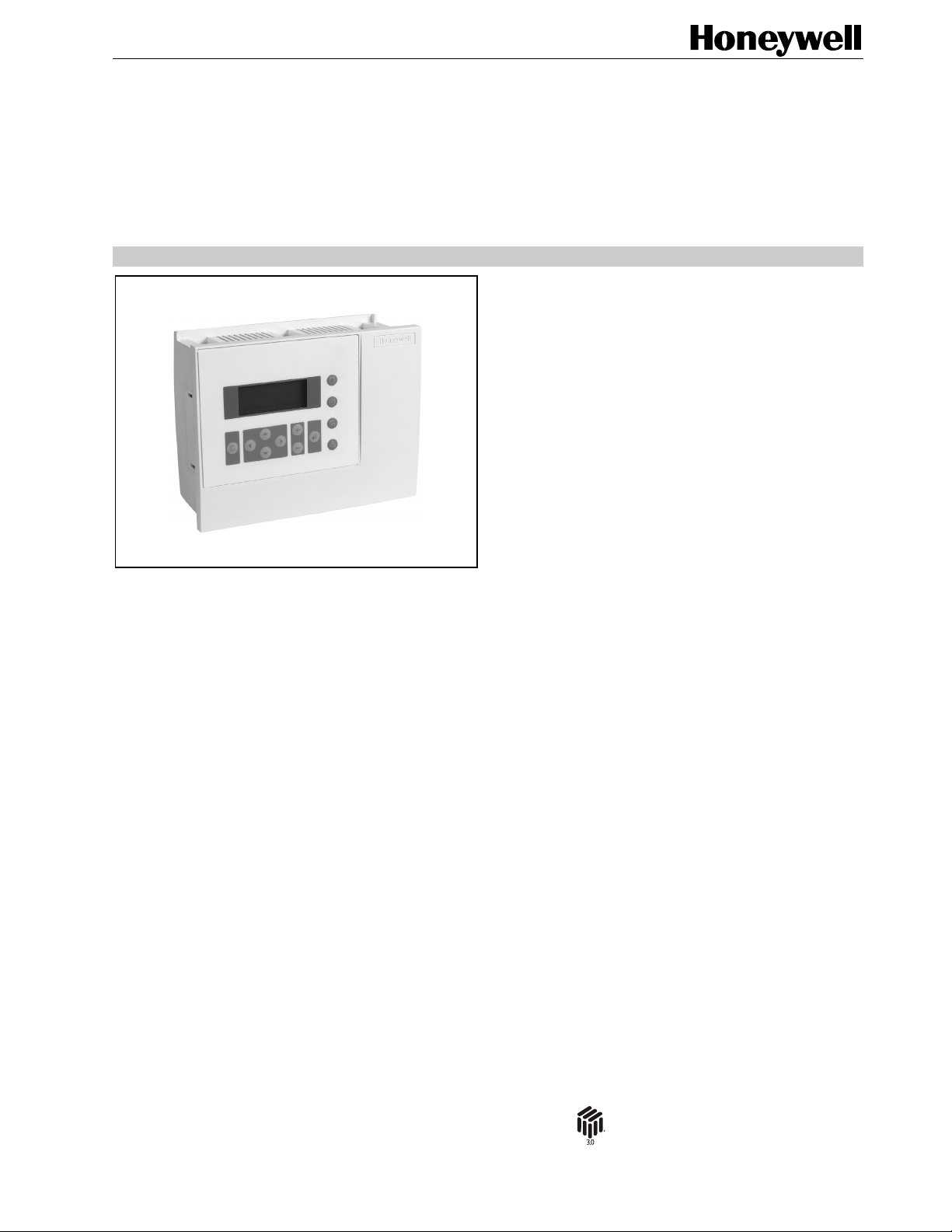
DESCRIPTION
The Excel 50 controller is available in two housing versions,
one with and one without a Man-Machine-Interface (MMI.)
The MMI version allows buswide access to other controllers.
The XI582 operator interface or the PC-based XL-Online
rd
operator and service software can be used in conjunction with
either version. The housing can be mounted inside a cabinet
on a DIN-rail or in a cabinet front door.
The Excel 50 has eight analog inputs, four analog outputs,
four digital inputs (three of which can be used as totalizers,)
and six digital outputs. The digital outputs allow the direct
drive of 3-position actuators (up to the max. load.) The controller can be wired either with screw terminal blocks directly
at the housing.) Pre-wiring is possible in both cases, and a
controller can be replaced without rewiring.
The application modules – all with Flash EPROM – are
available in five bus-wide access versions and one standalone version. They feature a variety of bus interfaces (see
Table 1.) Large RAMs provide for increased trending
capability.
All changeable parts or switches are accessible without
opening the housing. Communication capabilities and
memory are easily upgraded by replacing application
modules.
Excel 50
CONTROLLER
SPECIFICATION DATA
L
ONWORKS® bus, Meter-bus, or C-bus communication
Booster® reduces the number of required NVs and thus
also the number of required controllers; NV bindings can
be restored after controller reset (and thus need not be
redone after exchanging controllers); 46 NVs supported for
L
ONWORKS® integration
of pre-tested and fully documented applications
inside cabinet (DIN rail) or in cabinet front door
Remote Interface, XI882 Remote Touch-Panel Interface,
and XL-Online PC-based interface
ONWORKS® networks: NV-
® U.S. Registered Trademark
Copyright © 2015 Honeywell Inc. • All Rights Reserved EN0B-0088GE51 R0215
Page 2
EXCEL 50 CONTROLLER – SPECIFICATION DATA
SPECIFICATIONS
Versions
Housing
XL50A-MMI and XL50A-CY (with Man-Machine Interface);
XL50A (without MMI.)
Versions with MMI
Both the XL50A-MMI and the XL50A-CY feature a keypad
(with eight function keys and four fast-access keys) and an
LCD display.
The LCD display of the XL50A-MMI has four lines, 16
characters per line, adjustable contrast, and backlight.
The LCD display of the XL50A-CY features 128 X 64 dot
graphics, adjustable contrast, and backlight.
Application Modules
The Excel 50 controller can be upgraded by direct firmware
download via serial port or C-Bus. Contact your local
Honeywell affiliate for more information on the available
firmware and applications.
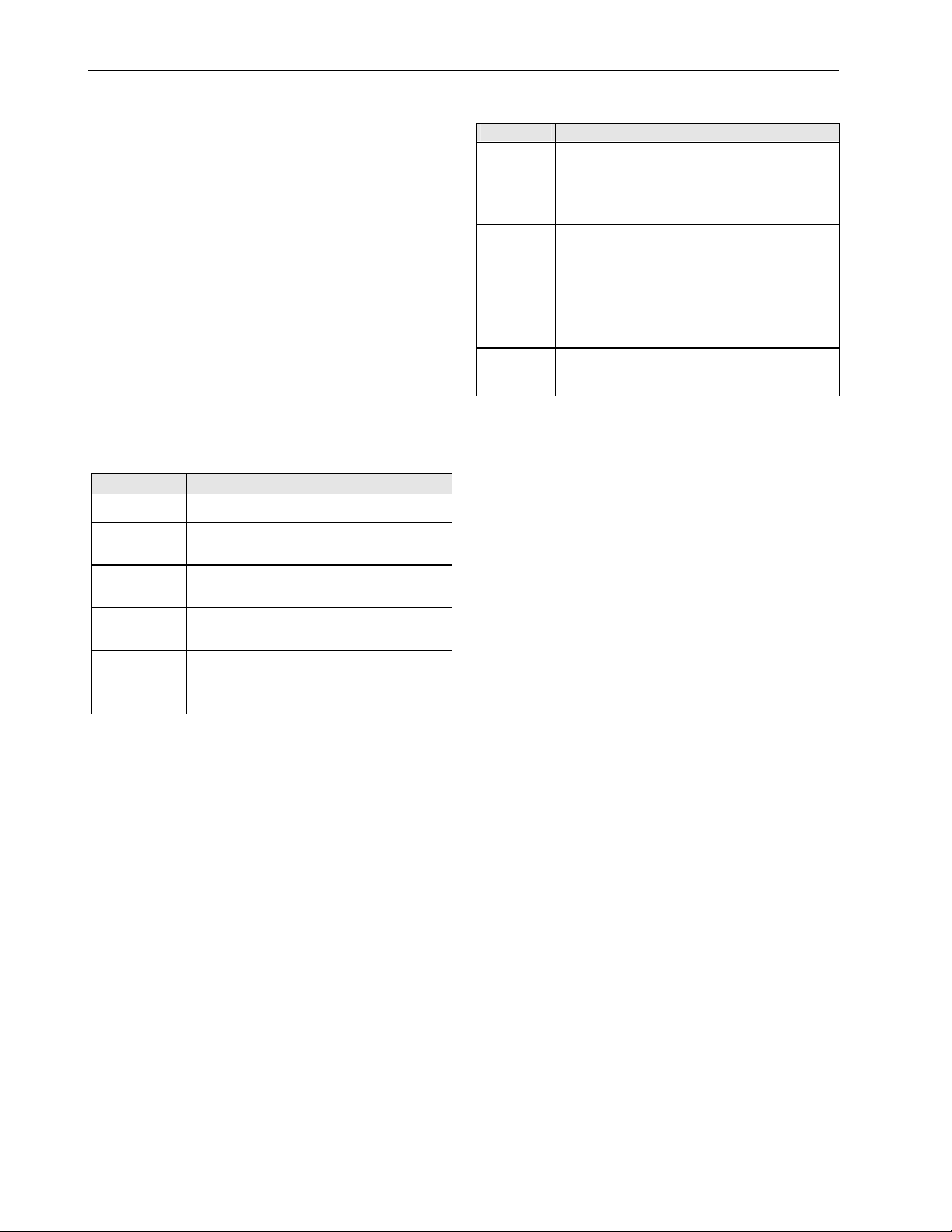
Table 1. Module versions
module description
XD50C-F
XD50C-FC
XD50C-FL
XD50C-FCL
XD50-FCS Bus-wide access via C-Bus / Meter-Bus; 1 MB
XD50-FLS Bus-wide access via LONWORKS® / Meter-Bus;
Mounting Options
Front door mounted with sealing ring.
Cabinet mounted on DIN-rail (rail clips shipped with device.)
I/O Terminal Connection
Screw terminal blocks directly attached to housing.
Power Supply
Voltage
24 Vac, ±20 %, 50/60 Hz from external transformer.
Current
3 A (2 A if digital output current 1.5 A.) In case of power
failure, the super gold capacitor saves RAM content and realtime clock for 72 hours (thus, no battery disposal necessary.)
Power Consumption
Max. 10 VA without load at digital outputs.
Stand-alone; 2 MB Flash EPROM; 256 KB RAM;
European and Chinese language support
Bus-wide access via C-Bus; 2 MB Flash EPROM;
256 KB RAM; European and Chinese language
support
Bus-wide access via L
Flash EPROM; 256 KB RAM; European and
Chinese language support
Bus-wide access via C-Bus /
2 MB Flash EPROM; 256 KB RAM; European
and Chinese language support
Flash EPROM; 256 KB RAM
2 MB Flash EPROM; 256 KB RAM
ONWORKS® Bus; 2 MB
LONWORKS® Bus;
Input/Output Specifications
type characteristics
eight analog
inputs
(universal)
four digital
inputs
four analog
outputs
(universal)
six digital
outputs
Voltage: 0...10 V (software-controlled switches
Current: 0...20 mA (via external 499 resistor)
Resolution: 10-bit
Sensor: NTC 20k, -58...+302 °F (-50...150 °C)
Voltage: max. 24 Vdc ( 2.5 V = logical status of
Voltage: 0...10 V, max. 11 V, ±1 mA
Resolution: 8-bit
Relay: via MCE3 or MCD3
Voltage: 24 Vac per triac
Current: max. 0.8 A, 2.4 A for all six triacs
for high impedance)
0, 5 V = logical status of 1,) 0...0.4 Hz
(0...15 Hz for three of four inputs when
used as totalizer, 4
parameter requirements)
together
th
input only for static
All inputs and outputs protected against overvoltage up to
24 Vac and 35 Vdc. Digital outputs protected against short
circuits via a changeable fuse (built-in fuse, 5 x 20 mm, 4 A
quick-blow.)
Bus and Port Connections
C-Bus Connection
Optional; located on application module. Up to 76.8 Kbaud,
switch provided for selectable termination.
ONWORKS® Bus Connection
L
Optional; located on application module. 78 Kbaud, FTT-10A
Free Topology Transceiver, using LonTalk® protocol.
Controller Serial Port Connection
9-pin Sub-D connector, RS 232, 9.6 Kbaud for XI582, XLOnline.
Meter-Bus Connection
Optional; located on application module. RS232 serial link
with RJ45 connector (PW3 Meter-Bus adapter also required.)
I/O Connectors
I/O Connector A: 26-pin port, digital outputs and power.
I/O Connector B: 34-pin port, analog and digital inputs, analog
outputs.
EN0B-0088GE51 R0215 2
Page 3

EXCEL 50 CONTROLLER – SPECIFICATION DATA
Environmental Ratings
Operating temperature: 0...50 °C (+32…+122°F)
Storage temperature: -20...+70 °C (-4…+158°F)
Relative humidity: 5...93% non-condensing
Purpose: for home (residential, commer-
cial, and light-industrial) environments
Construction: for incorporate mounting in
cabinets
RFI, EMI according to CE regulations
Pollution degree: Class II
Action: Type 1
Software: Class A
Impulse voltage: 500 V
Protection Standards
IP54 (when front-door mounted with MMI in a cabinet
conforming to IP54 and use of ACC3 mounting clamps and
sealing ring.)
IP20 (when wall-mounted: both with and without MMI.)
UL94-0: Flame-retardant class of housing material.
Certifications
CE
UL 916 and cUL
Meets FCC Part 15, Subpart J for Class A equipment.
Application Module
Firmware
The firmware is downloadable via the PC-based XL-Online
operator and service software or C-Bus.
Housing
Plug-in plastic module, wired with screws.
Application Module LEDs and Ports
LonWorks service button
POWER, GREEN
LonWorks service LED, RED
XD50-FLS
1 2 3
A1
A2
not used
LonWorks BUS
M-BUS TxD, YELLOW
M-BUS RxD, YELLOW
RESERVED
METER BUS
(RJ45 JACK)
LEDs
XD50C-FCL
1 2 3
A1
LonWorks BUS
Fig. 1. Application modules (examples)
4 5 6
C-
A2
C+
SHIELD
not used
LonWorks service button
POWER, GREEN
LonWorks service LED, RED
C-BUS TxD, YELLOW
C-BUS RxD, YELLOW
RESERVED
C-BUS TERMI-
NATION SWITCH
C-BUS
TOP
MIDDLE
BOTTOM
Terminal Blocks
fuse
(4 A, quick-acting)
block A block B
Fig. 2. Removable screw terminal blocks
Block A
24 Vac24 Vac
24 Vac24 Vac
5
1
3
7 9 11 13
42
{
DO1 DO2 DO3 DO4 DO5 DO6
15 33
19
LEDs
16 34
{{{{{{{{{{{{{{{
AO1 AI1AO2 AI2AO3 AI3AO4 AI4DI1
1086
{
{
2117
Fig. 3. Terminal assignment of screw terminal blocks
port for
application
module
port Bport A
hardware
adjustment
reset
for LCD
serial port
12
14
{
{
{
Block B
26 4424 4222 4020 3818 36
28 4630 32 48
DI2 AI6DI3 AI7DI4 AI8
+10 V / 5 mA REF. DI-POWER
{
AGNDGND
37 39234125 43274529 31 4735
AI5
{
3 EN0B-0088GE51 R0215
Page 4

EXCEL 50 CONTROLLER – SPECIFICATION DATA
Dimensions
100
198
cut-out: 186
port for
application
module
70
81
106
34 34
72
1 2
cut-out: 138 150
fuse
hardware
reset
port Bport A
adjustment
for LCD
serial port
85 85
97
126
DIN rail clip position
for models without MMI
1
DIN rail clip position
for models with MMI
2
Manufactured for and on behalf of the Environmental and Combustion Controls Division of Honeywell Technologies Sàrl, Rolle, Z.A. La Pièce 16, Switzerland by its Authorized Representative:
Automation and Control Solutions
Honeywell GmbH
Böblinger Strasse 17
71101 Schönaich, Germany
Phone +49 (0) 7031 637 01
Fax +49 (0) 7031 637 740
http://ecc.emea.honeywell.com
EN0B-0088GE51 R0215 Subject to change without notice
 Loading...