

Page 1
Solid Core and Split Core 4-20 mA
WARNING
CAUTION
CAUTION
Output Current Sensors
CTS-20; CTP-20
INSTALLATION INSTRUCTIONS
SAFETY
For CTS-20 Series current sensors, ensure
that all power sources are disconnected and
locked out before installation as severe injury
or death may result from electrical shock due
to contact with high voltage wires.
This product is not intended to be used for life
or safety applications.
This product is not intended for use in any
hazardous or classified locations.
INSTALLATION
Make sure that all installations are in compliance with all
national and local electrical codes. Only qualified
individuals that are familiar with codes, standards, and
proper safety procedures for high-voltage installations
should attempt installation. The current sensor is a 2wire, 4 to 20 mA Loop Powered device that requires a
regulated +12 to 30 Vdc external power source.
IMPORTANT
The current switch should be used on insulated
conductors only!
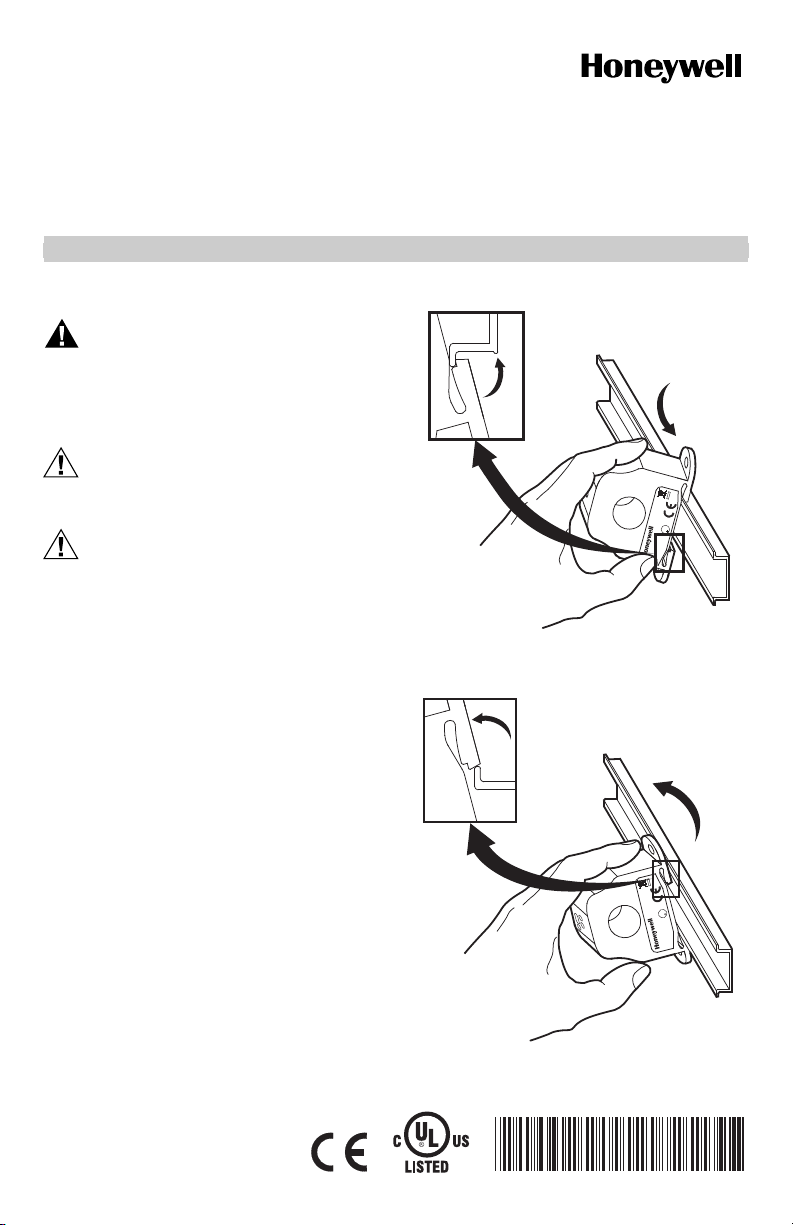
The current sensors may be mounted in any position
using the two (2) #8 x 3/4 in (19 mm) Tek screws and the
mounting holes in the base or snapped directly on to the
1-3/8 in. (35 mm) DIN rail (See Figures 3 and 4). Leave a
minimum distance of 1 in. (25 mm) between the current
sensor and any other magnetic devices such as
contactors and transformers.
3X
Fig. 1. Sensor placed on DIN rail
3X
S
U
L
R
U
C
M25289
S
U
L
R
U
C
IND.CONT.EQ.
3JHX
M25290
Fig. 2. Sensor removed from DIN rail
62-0245—01
Page 2
SOLID CORE AND SPLIT CORE 4-20 MA OUTPUT CURRENT SENSORS
WARNING
CAUTION
Latch Operation (Split Core Models)
Pressing down on the two (2) side tabs and swinging the
The secondary of the 5A Current Transformer
(C.T.) must be shorted together before the
power may be turned on from the device.
For applications in which the normal operating current is
greater than 200 or 250 Amps, depending on the model,
or for conductor diameters larger than 0.75 in. (19 mm) in
diameter, an external 5 Amp Current Transformer (C.T.)
must be used in conjunction with a CTS20-005 or CTS20005VFD as shown in Fig. 5.
INSULATED CONDUCTOR
600:5 RATIO 5A C.T.
WIRE NUT
cover open, opens the split core current switch as shown
in Fig. 6. Lifting up the latch with a flat-tip screwdriver as
shown in Fig. 7 can also open the unit. Press down firmly
on the cover to close the current switch. An audible “click”
will be heard as the tab slides over the tongue on the
base.
Mating surfaces of the magnetic core are
exposed when the sensor is open. Silicone
grease, present on the cores to prevent rust,
can capture grit and dirt if care is not
exercised. Operation can be impaired if
anything prevents good contact between pole
pieces. Visually check the mating parts of the
core before closing the current sensor.
EXAMPLE: FOR CURRENTS UP TO 600 AMPS, USE A 600:5 RATIO C.T.
AS SHOWN.
Fig. 3. Current transformer
US
L
R
U
C
Fig. 4. Opening sensor by hand
US
L
R
U
C
M25299
Fig. 5. Opening with a screwdriver
M25295A
S
U
L
R
U
C
Wiring
Honeywell recommends the use of 16 to 22 AWG (1.3 to
2
) shielded cable, copper wire only for all current
0.3 mm
sensor applications. A maximum wire length of less than
98.4 feet (30 meters) should be used between the current
sensors and the Building Management System or
controller.
NOTE: When using a shielded cable, be sure to connect
only (1) end of the shield to ground at the
controller. Connecting both ends of the shield to
ground may cause a ground loop.
When removing the shield from the sensor end, make
sure to properly trim the shield so as to prevent any
chance of shorting. The current sensor terminals are
polarity sensitive and represent a linear and proportional
4 to 20 mA output signal. The current sensors are
available in either an Average or True RMS output
version. The recommended torque to be used on the
terminal block connections is 5.93 in-lbs (0.67 Nm). The
M25298
62-0245—01 2
Page 3

SOLID CORE AND SPLIT CORE 4-20 MA OUTPUT CURRENT SENSORS
aperture (hole) size of the current sensor is
3/4 in. (19 mm) and will accept a maximum cable
diameter of 350 MCM (17.3 mm).
+
+12-30 VDC
–
DC POWER SUPPLY
–
+
+ 4-20 MA SIGNAL INPUT
COMMON
GND (SHIELD)
BUILDING AUTOMATION
SYSTEM
M23934
Fig. 6. Wiring example
OPERATING SPECIFICATIONS
Max Sensing Current Voltage: 600 Vac
Table 1. Specifications by Product Number
Product Number
Core
Type Output Range Jumper
CTS-20-005-AVG-001 Solid 4-20 mA Average 0-5 Amps Fixed None 100 Amps 125 Amps
CTS-20-050-AVG-001 Solid 4-20 mA Average 0-10 Amps
CTS-20-250-AVG-001 Solid 4-20 mA Average 0-100 Amps
b
CTS-20-005-VFD-001
CTS-20-050-VFD-001
CTS-20-250-VFD-001
Solid 4-20 mA True RMS 0-5 Amps Fixed None 60 Amps 100 Amps
b
Solid 4-20 mA True RMS 0-10 Amps
b
Solid 4-20 mA True RMS 0-100 Amps
0-20 Amps
0-50 Amps
0-200 Amps
0-250 Amps
0-20 Amps
0-50 Amps
0-200 Amps
0-250 Amps
Low
Middle
High
Low
Middle
High
Low
Middle
High
Low
Middle
High
CTP-20-005-AVG-001 Split 4-20 mA Average 0-5 Amps Fixed None 100 Amps 125 Amps
CTP-20-050-AVG-001 Split 4-20 mA Average 0-10 Amps
CTP-20-200-AVG-001 Split 4-20 mA Average 0-100 Amps
b
CTP-20-005-VFD-001
CTP-20-050-VFD-001
CTP-20-200-VFD-001
a
All current sensors are shipped from the factory with the jumper set in the high range.
b
All VFD models have True RMS outputs and should be used with Variable Frequency Drives. Not CE compliant at
this time.
Split 4-20 mA True RMS 0-5 Amps Fixed None 60 Amps 100 Amps
b
Split 4-20 mA True RMS 0-10 Amps
b
Split 4-20 mA True RMS 0-100 Amps
0-20 Amps
0-50 Amps
0-150 Amps
0-200 Amps
0-20 Amps
0-50 Amps
0-150 Amps
0-200 Amps
Low
Middle
High
Low
Middle
High
Low
Middle
High
Low
Middle
High
Max. Current
a
Continuous
100 Amps
150 Amps
200 Amps
200 Amps
360 Amps
400 Amps
60 Amps
100 Amps
160 Amps
160 Amps
320 Amps
400 Amps
100 Amps
150 Amps
200 Amps
135 Amps
180 Amps
250 Amps
60 Amps
100 Amps
160 Amps
135 Amps
180 Amps
250 Amps
Max. Current
for 6 secs.
125 Amps
225 Amps
300 Amps
250 Amps
450 Amps
500 Amps
80 Amps
200 Amps
300 Amps
200 Amps
400 Amps
500 Amps
125 Amps
225 Amps
300 Amps
200 Amps
300 Amps
400 Amps
80 Amps
200 Amps
300 Amps
200 Amps
300 Amps
400 Amps
3 62-0245—01
Page 4

SOLID CORE AND SPLIT CORE 4-20 MA OUTPUT CURRENT SENSORS
TROUBLESHOOTING
Problem Solution
No reading • Confirm that you have +12 to 30 Vdc in series with the current sensor output terminals
Erratic readings • Verify that the wires are terminated properly.
Inaccurate readings • If you suspect that the current sensor is not reading within the accuracy specifications,
and the analog input of the control panel.
• Check the polarity of the circuit.
• Verify that the terminals are screwed down, wires are firmly in place.
• Disconnect the input to the control panel and then insert a current meter (mA range) in
series with the current sensor output to verify that the circuit is working properly.
• Check that the +12 to 30 Vdc input is clean. In areas of high RF interference, shielded
cable may be necessary to stabilize signal.
please contact the factory for assistance.
CURRENT CONVERSION FORMULA
To convert the current sensor output signal to a current
reading.
Current reading = mA output/20 mA x Amp Span.
For example:
For a reading of 4 mA with a 0-250 Amp span:
Current reading = (4 mA/20 mA) x 250 A = 0 Amp.
(0/16) X 250 = 0
NOTE: 4 mA = 0 Amps
20 mA = 250 Amps
Automation and Control Solutions
Honeywell International Inc. Honeywell Limited-Honeywell Limitée
1985 Douglas Drive North 35 Dynamic Drive
Golden Valley, MN 55422 Toronto, Ontario M1V 4Z9
customer.honeywell.com
® U.S. Registered Trademark
© 2007 Honeywell International Inc.
62-0245—01 C.H. Rev. 06-07
 Loading...