

Page 1
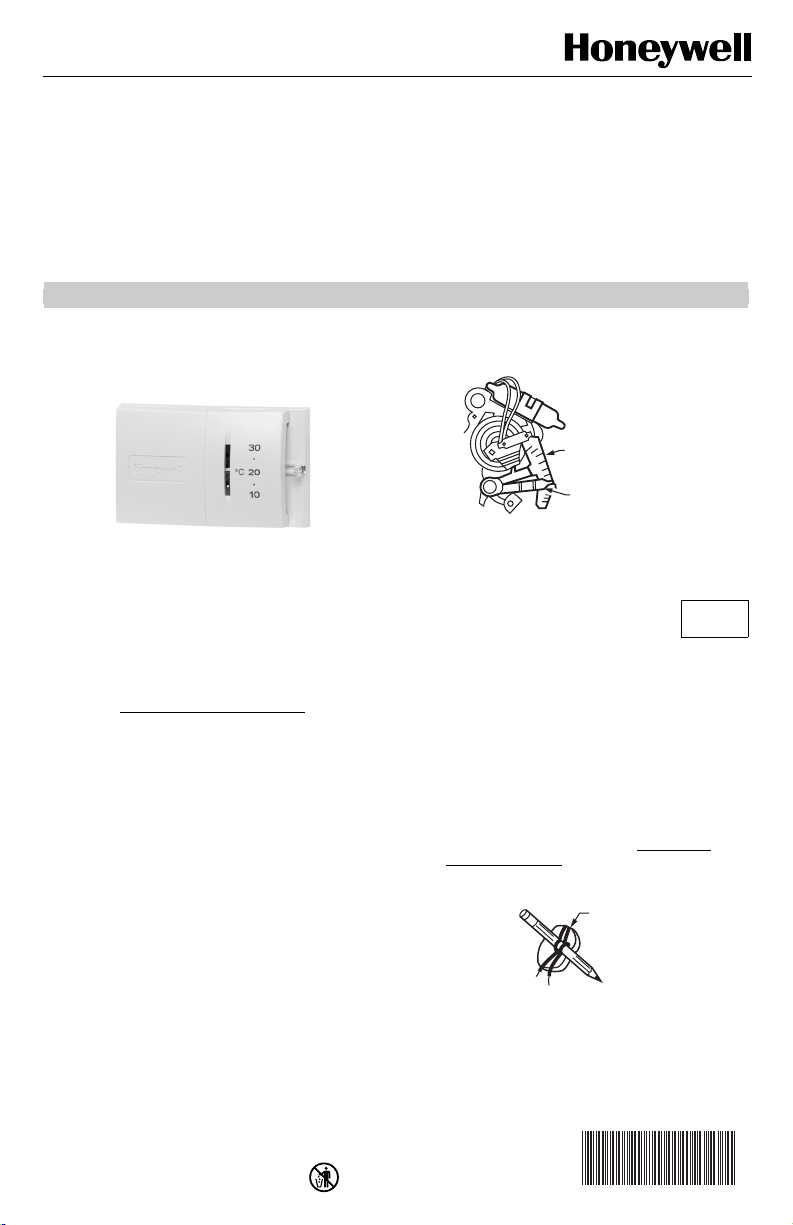
CT54 Thermostat
WIRES
H
5
INSTALLATION INSTRUCTIONS
STEP 1. PREPARE FOR
INSTALLATION
The CT54 Thermostat controls 2-wire, 15 Vac to 30 Vac,
gas, oil or electric heating-only systems.
The CT54 Thermostat is not suitable for:
• cooling systems
• heating-cooling systems
• 3-wire electric heating systems
If you are unsure which thermostat model is right for your
system, visit www.honeywell.com/yourhome
Honeywell Customer Care at 1-800-468-1502.
1. Check that the following components are included:
• Thermostat
• Two one-inch screws
• Installation Instructions
2. Required tools:
• Slotted screwdriver
• Drill
• Drill bit (1/16 in.)
• Needle nose pliers
• Level
• Pencil
or call
3. Locate the heat anticipator scale and the heat
anticipator lever on the old thermostat (see Fig. 1).
OLD THERMOSTAT HEAT
ANTICIPATOR SCALE
HEAT ANTICIPATOR LEVER
TYPICAL LOCATION OF HEAT
ANTICIPATOR SCA
Fig. 1. Heat anticipator on old thermostat (example).
4. Record the number that the heat
anticipator lever points to on the heat
anticipator scale.
NOTE: If you cannot find the heat anticipator setting on
your thermostat, you can use a standard setting
for your type of system when you reach Step 5.
Set Heat Anticipator On New Thermostat.
5. Remove the screw or screws that hold the thermo-
stat to the wall and pull the thermostat away from
the wall.
6. Remove the two wires from the old thermostat and
wrap them around a pencil to keep them from falling back into the wall (see Fig. 2). If there are more
than two wires connected to your old thermostat,
do not remove the wires. Visit www.honeywell.com/yourhome or call 1-800-468-1502 for further assistance with the installation.
LE
AND
THROUG
WALL
OPENING
LEVE
R
M21192
STEP 2. REMOVE OLD
THERMOSTAT
1. Turn power off to the system at the furnace or at
the fuse/circuit breaker panel.
2. If the cover does not easily pull off, remove any
screws that may fasten the cover to the thermostat.
® U.S. Registered Trademark
Copyright © 2003 Honeywell International Inc. • • All Rights Reserved
M1964
Fig. 2. Pull wires through wall opening.
69-1696EF
Page 2
CT54 THERMOSTAT
6
7
F
I
7
T
)
G
MERCURY NOTICE
If this thermostat is replacing a control that
contains mercury in a sealed tube, do not place
the old thermostat in the trash. Contact your local
waste management authority for instructions
regarding recycling and proper disposal of this
control or of an old control containing mercury in
a sealed tube.
STEP 3. CONNECT WIRES TO NEW
THERMOSTAT
IMPORTANT
All wiring must comply with local building codes
and ordinances. If you are unsure about household wiring procedures, please call your local
heating/cooling contractor.
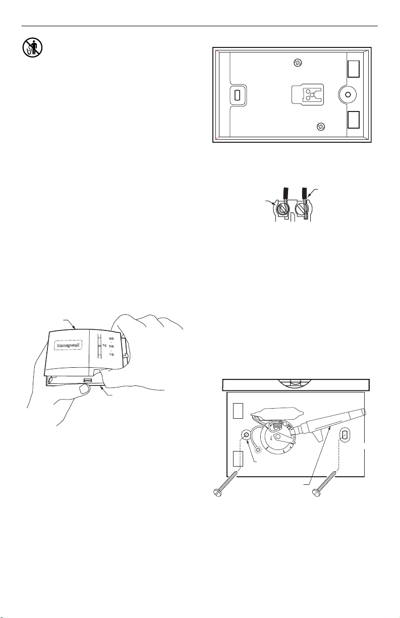
1. Remove the cover on the new thermostat. To
remove the cover, insert your thumb into the indentation on the bottom and pull the cover away from
the thermostat (see Fig. 3).
2. Loosen the R and W terminal screws on the back
of the new thermostat (see Fig. 4).
3. Remove the two wires from the pencil and attach
one wire to the R terminal and the other wire to the
W terminal (see Fig. 4 and 5).
4. Plug the hole in the wall with insulation to prevent a
warm or cool draft from affecting the operation of
the thermostat.
COVER
R
W
M1964
Fig. 4. R and W terminals on new thermostat.
OR WRAPAROUND
NSERTION STRIP
/16 IN. (11 MM)
FOR STRAIGH
INSERTION
STRIP
5/16 IN. (8 MM
M19648
Fig. 5. Wraparound and straight wiring connections.
STEP 4. MOUNT NEW
THERMOSTAT TO WALL
Position the thermostat on the wall. Place a level
1.
on top of the thermostat and use a pencil to mark
the two mounting holes on the wall (see Fig. 6).
2. Move the thermostat to the side and drill the
mounting holes in the wall using a 1/16 in. drill bit
at the locations you marked.
3. Position the thermostat over the drilled holes and
loosely insert the mounting screws into the drilled
holes. Check the leveling of the thermostat and
tighten the mounting screws. Do not over tighten.
LEVEL
BOTTOM OF
THERMOSTAT
Fig. 3. Remove cover on new thermostat.
69-1696EF 2
M1964
DATE CODE
MODEL NO.
.18
.9
.2
.7
.5
L
.4
R
O
E
N
G
.25
.3
MOUNTING
HOLE
NOTE: MOVE TEMPERA TURE
LEVER IF IT BLOCKS
MOUNTING HOLE
MOUNTIN
HOLE
M19649
Fig. 6. Mount new thermostat to wall.
Page 3
CT54 THERMOSTAT
M19650
H
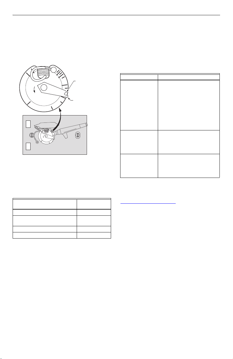
STEP 5. SET HEAT ANTICIPATOR
ON NEW THERMOSTAT
1. Set the heat anticipator lever to the number that
you recorded in Step 2. Remove Old Thermostat,
sub-step 4 (see Fig. 7).
HEAT ANTICIPATOR
.18
.2
L
.25
DATE CODE
MODEL NO.
Fig. 7. Heat anticipator on new thermostat.
2. If you could not find a heat anticipator setting on
your old thermostat, use the setting listed in
Table 1 for your type of heating system.
Table 1. Heat Anticipator Setting.
Heating System
Hot Water .8
High Efficiency Warm Air (90% or
better)
Gas or Oil Warm Air .4
Electric .3
.9
.7
.5
.4
R
O
E
N
G
.3
.18
.9
.2
.7
.5
L
.4
R
O
E
N
G
.25
.3
THIS POINT
SHOULD ALIGN WIT
HEAT ANTICIPATOR
SETTING
PLACE FINGER
HERE TO MOVE
LEVER
Heat Anticipator
Setting (Amps)
.8
STEP 6. OPERATING NEW
THERMOSTAT
1. Adjust the temperature setting lever to your desired
setting. If it is too warm, lower the temperature setting. If it is too cool, raise the temperature setting.
IF YOU HAVE A PROBLEM
If. . . Then. . .
Heating system
does not come on.
Heating system runs
too long to maintain
a comfortable
temperature.
Heating system
needs to run longer
to maintain a
comfortable
temperature.
Customer Assistance
Please read and follow the provided instructions for this
thermostat. For additional information, go to
www.honeywell.com/your home
Customer Care at 1-800-468-1502.
Before calling, please have the following information
available:
• Thermostat model number and date code (refer to Fig.
6 for the location of the model number and date code).
• Type of heating system (for example: gas or oil; warm
air, hot water).
• Make sure the temperature
setting is above the room
temperature.
• Make sure the circuit breaker
is not tripped and reset it if
necessary.
• Make sure the power switch at
the equipment is in the On
position.
• Wait 5 minutes for the system
to respond.
• Verify the thermostat is level.
• Adjust heat anticipator lever
clockwise one scale mark (see
Fig. 7). Do not adjust heat
anticipator below .3 Amps.
• Verify the thermostat is level.
• Adjust heat anticipator lever
counterclockwise, in the
direction of the arrow, one
scale mark (see Fig. 7).
or call Honeywell
Place the cover on the thermostat and turn the
3.
power back on. If the heating system runs too long
to maintain a comfortable temperature, adjust heat
anticipator lever clockwise one scale mark (see Fig.
7). Do not adjust heat ancitipator below .3 Amps. If
the heating system needs to run longer to maintain
a comfortable temperature, adjust heat anticipator
lever counterclockwise, in the direction of the arrow,
one scale mark (see Fig. 7).
3 69-1696EF
Page 4

Automation and Control Solutions
Honeywell International Inc. Honeywell Limited-Honeywell Limitée
1985 Douglas Drive North 35 Dynamic Drive
Golden Valley, MN 55422 Scarborough, Ontario
M1V 4Z9
69-1696EF J.S. 9-03 www.honeywell.com/yourhome
Printed in U.S.A. on recycled
paper containing at least 10%
post-consumer paper fibers.
Page 5

Thermostat CT54
NOTICE D'INSTALLATION
ÉTAPE 1. AVANT L’INSTALLATION
Le thermostat CT54 sert à commander des systèmes de
chauffage seulement, bifilaires, de 15 à 30 V c.a., au gaz,
au mazout ou à l’électricité.
Le thermostat CT54 ne convient pas à ce qui suit :
• systèmes de refroidissement
• systèmes de chauffage-refroidissement
• systèmes de chauffage électrique à trois fils
Si vous ne savez pas avec certitude quel thermostat
convient à votre système, consultez le site
www.honeywell.com/yourhome ou composez le numéro
sans frais des services à la clientèle de Honeywell :
1-800-468-1502.
1. S’assurer que les articles suivants sont inclus :
• Thermostat
• Deux vis de 2,54 cm (1 po).
• Directives d’installation
2. Outils requis :
• Tournevis pour écrou à fente
• Perceuse
• Mèche de perceuse (1/16 po)
• Pinces à long bec
• Niveau
• Crayon
ÉTAPE 2. RETRAIT DE L’ANCIEN
THERMOSTAT
1. Couper l’alimentation du système à l’appareil de
chauffage ou au tableau de fusibles/disjoncteurs.
2. Si le couvercle est difficile à enlever, retirer toute
vis qui retiendrait le couvercle au thermostat.
3. Repérer l’échelle de la résistance anticipatrice de
chaleur et le doigt de réglage de la résistance
anticipatrice de chaleur de l’ancien thermostat (voir
la Fig. 1).
ÉCHELLE DE LA RÉSISTANCE ANTICIPATRICE
DE CHALEUR DE L'ANCIEN THERMOSTAT
DOIGT DE RÉGLAGE DE LA RÉSISTANCE
EMPLACEMENT TYPE DE L'ÉCHELLE DE LA RÉSISTANCE
ANTICIPATRICE DE CHALEUR
Fig. 1. Résistance anticipatrice de l’ancien
4. Inscrire le chiffre vers lequel pointe le
doigt de réglage de la résistance
anticipatrice de chaleur.
REMARQUE : S’il est impossible de repérer le réglage
5. Retirer la ou les vis qui retiennent le thermostat au
mur et retirer le thermostat en tirant vers soi.
6. Retirer les deux fils de l’ancien thermostat et les
enrouler autour d’un crayon pour les empêcher de
glisser dans le mur (voir la Fig. 2). S’il y a plus de
deux fils raccordés à l’ancien thermostat, ne pas
enlever les fils. Consulter le site www.honeywell.com/yourhome ou composer le 1-800-4681502 pour obtenir de l’aide sur l’installation.
thermostat (exemple).
de la résistance anticipatrice de l’ancien
thermostat, régler la résistance du nouveau thermostat à celle qui correspond au
type de système de chauffage à l’étape 5.
Réglage de la résistance anticipatrice
de chaleur du nouveau thermostat.
MF21192
® Marque de commerce déposée aux É.-U.
Copyright © 2003 Honeywell International Inc. • Tous droits réservés •
69-1696EF
Page 6

THERMOSTAT CT54
FILS À TRAVERS
6
7
NIVEAU
9
L'OUVERTURE
DANS LE MUR
MF19645
Fig. 2. Faire passer les fils par l’ouverture dans le
mur.
R
AVIS DE RECYCLAGE
Si le nouveau thermostat remplace un ancien
régulateur contenant un contact à mercure, ne
pas mettre l’ancien régulateur aux poubelles.
Communiquer plutôt avec le service local de
cueillette des déchets pour obtenir de
l’information sur le recyclage ou sur la bonne
façon de disposer d’un ancien régulateur
contenant un contact à mercure.
ÉTAPE 3. RACCORDEMENT DES
FILS AU NOUVEAU THERMOSTAT
IMPORTANT
Tout le câblage doit être conforme au code du
bâtiment et aux règlements locaux. Si vous
n’êtes pas certain de la marche à suivre,
veuillez communiquer avec un entrepreneur
local en chauffage-refroidissement.
1. Retirer le couvercle du nouveau thermostat. Pour
retirer le couvercle, insérer le pouce sous le renfoncement au bas de l’appareil et éloigner le couvercle du thermostat en tirant (voir la Fig. 3).
2. Dévisser les vis des bornes R et W au dos du nouveau thermostat (voir la Fig. 4).
3. Enlever le crayon qui servait à retenir les fils, et
fixer un fil à la borne R et l’autre à la borne W (voir
les figures 4 et 5).
4. Obstruer l’ouverture dans le mur à l’aide d’isolant
pour éviter qu’un courant d’air chaud ou froid ne
nuise au fonctionnement du thermostat.
COUVERCLE
W
M1964
Fig. 4. Bornes et R et W du nouveau thermostat.
POUR CONNEXION
ENROULÉE
7/16 PO (11 MM)
POUR CONNEXION
DROITE
5/16 PO (8 MM)
MF19648
Fig. 5. Connexion droite et connexion enroulé.
ÉTAPE 4. INSTALLATION DU
NOUVEAU THERMOSTAT AU MUR
1. Placer le thermostat sur le mur. Placer un niveau
sur le dessus du thermostat et utiliser un crayon
pour marquer l’emplacement de deux ouvertures
de fixation (voir la Fig. 6).
2. Mettre le thermostat de côté et percer dans le mur
aux endroits marqués au crayon deux ouvertures
de fixation à l’aide d’une mèche de 1/16 po.
3. Placer le thermostat par-dessus les deux ouvertures ainsi pratiquées et insérer les vis de fixation
dans les ouvertures, sans les serrer. Vérifier si le
thermostat est de niveau, puis resserrer les vis de
fixation. Ne pas trop serrer.
BAS DU THERMOSTAT
MF1964
Fig. 3. Retirer le couvercle du nouveau thermostat.
69-1696EF 2
DE MODÈLE
o
CODE DE DATE
N
.18
.9
.2
.7
.5
L
.4
R
O
E
N
G
.25
.3
OUVERTURE
DE FIXATION
REMARQUE : DÉPLACER LE
DOIGT DE RÉGLAGE DE LA
RÉSISTANCE S'IL BLOQUE
L'OUVERTURE DE FIXATION
OUVERTURE
DE FIXATION
MF1964
Fig. 6. Installation du nouveau thermostat au mur.
Page 7

THERMOSTAT CT54
R
RÉSISTANCE ANTICIPATRICE DE CHALEUR
ÉTAPE 5. RÉGLAGE DE LA
RÉSISTANCE ANTICIPATRICE DE
CHALEUR DU NOUVEAU
THERMOSTAT
1. Régler le doigt de réglage de la résistance anticipatrice de chaleur au chiffre pris en note l’étape 2.
Retirer l’ancien thermostat, sous-étape 4 (voir la
Fig. 7).
.18
.2
CODE DE DATE
Fig. 7. Résistance anticipatrice de chaleur du
2. Si vous n’avez pas été en mesure de trouver le
réglage de la résistance anticipatrice de l’ancien
thermostat, consultez le tableau 1 en fonction du
type de votre système de chauffage.
Tableau 1. Réglage de la résistance anticipatrice de
Systèmes de chauffage
Eau chaude .8
Système à air chaud à haut
rendement (90 % ou plus)
Gaz ou mazout Air chaud .4
Électrique .3
3. Remettre le couvercle du thermostat et rétablir l’alimentation électrique. Si le système de chauffage
fonctionne trop longtemps pour que la température
ambiante soit confortable, ajuster la résistance
anticipatrice de chaleur dans le sens horaire d’une
marque sur l’échelle (voir la Fig. 7). Ne pas régler
la résistance à moins de 0,3 A. Si le système de
chauffage doit fonctionner plus longtemps pour
que la température ambiante soit agréable, régler
la résistance anticipatrice de chaleur dans le sens
antihoraire, dans le sens de la flèche, d’une
marque sur l’échelle (voir la Fig. 7).
.9
L
R
O
E
N
G
.25
.3
DE MODÈLE
o
N
.18
.9
.2
.7
.5
L
.4
R
O
E
N
G
.25
.3
nouveau thermostat.
.7
CE POINT DOIT ÊTRE VIS-À-VIS
LE RÉGLAGE DE LA
RÉSISTANCE ANTICIPATRICE
.5
DE CHALEUR
.4
PLACER LE DOIGT ICI POUR DÉPLACE
LE DOIGT DE RÉGLAGE DE LA
RÉSISTANCE ANTICIPATRICE DE
CHALEUR
chaleur.
Réglage de la résistance
anticipatrice de chaleur
.8
MF19650
(A)
ÉTAPE 6. FONCTIONNEMENT DU
NOUVEAU THERMOSTAT
1. Ajuster le doigt de réglage de la température au
point de consigne désiré. S’il fait trop chaud, abaisser le réglage. S’il fait trop froid, augmenter le
réglage.
EN CAS DE PROBLÈME
Si. . . Alors. . .
Le système de
chauffage ou de
refroidissement ne
se met pas en
marche.
.Le système de
chauffage
fonctionne trop
longtemps pour que
la température soit
agréable.
Le système de
chauffage doit
fonctionner plus
longtemps pour que
la température soit
agréable.
Services à la clientèle
Veuillez lire les directives fournies avec le thermostat.
Pour obtenir d’autres renseignements, consultez le site
www.honeywell.com/yourhome ou composer le numéro
d’assistance sans frais de Honeywell : 1-800-468-1502.
Avant de composer, assurez-vous d’avoir en main
l’information suivante :
• Numéro de modèle du thermostat et code de date
(voir la Fig. 6 pour savoir où trouver le numéro de
modèle et le code de date).
• Type de système de chauffage (p. ex. gaz ou mazout;
air chaud, eau chaude).
• S’assurer que le point de
consigne est plus élevé que la
température ambiante.
• S’assurer que le coupe-circuit
n’est pas déclenché et le
remettre en position de marche
au besoin.
• S’assurer que l’interrupteur du
système est à la position de
marche (ON).
• Attendre 5 minutes pour laisser
au système le temps de réagir.
• Vérifier si le thermostat est de
niveau.
• Ajuster le doigt de réglage de
la résistance dans le sens
horaire d’une marque sur
l’échelle (voir la Fig. 7). Ne pas
régler la résistance à moins de
0,3 A.
• Vérifier si le thermostat est de
niveau.
• Régler la résistance
anticipatrice de chaleur dans le
sens antihoraire, dans le sens
de la flèche, d’une marque sur
l’échelle (voir la Fig. 7).
3 69-1696EF
Page 8

r
Solutions de régulation et d'automatisation
Honeywell International Inc. Honeywell Limited-Honeywell Limitée
1985 Douglas Drive North 35, Dynamic Drive
Golden Valley, MN 55422 Scarborough (Ontario)
M1V 4Z9
69-1696EF J.S. 9-03 www.honeywell.com
Imprimé aux États-Unis sur du papie
recyclé contenant au moins 10 %
de fibres post-consommation.
 Loading...