

Page 1
Honeywell
CT50a7ct51A,
CT52A, CT53A
Thermostats
INSTALLATiON iNSTBUCTIONS
CT50A is for most gas and oil
heating systems.
CT51A is for most gas and oil heating or
electric cooling systems.
CT52A is tor most electric
heating systems.
CT53A is for millivoltage heating systems.
Do-it-yourself models
Proper installation of your
Honeywell thermostat will
occur if you follow instructions
□
STEP-BY-STEP. It is recom
mended that as you read,
understand and complete each
step, you check 0 'f ofi with
pencil or pen.
CT50A
YOUR
HONEYWELL
THERMOSTAT
Your new Honeywell CT50A
Heating Thermostat will replace
most 15 to 30 V, 2-wire heating
system thermostats. The CT50A
is suitable only for gas or oil
heating systems (NOT for
heating/cooling, heat pump, or
electric heating systems).
Your new Honeywell CT51A
Heating/Cooling Thermostat will
replace most 15 to 30 V, 4-wire,
heating/cooling system
Check thermostat
suitability tor your home's
system by reviewing YOUR
□
HONEYWELL THERMOSTAT
section, above.
thermostats. The CT51A is
suitable only for gas or oil
heating/cooling or electric
cooling systems (NOT for heat
pump or electric heating
systems).
Your new Honeywell CT52A
Heating Thermostat will replace
most 15 to 30 V, 4-wire electric
heating system thermostats
(NOT for cooling, heating/
cooling, heat pump, gas or oil
systems).
Your new Honeywell CT53A
Heating Thermostat is suitable
tor 250, 500 or 750 mV heating
systems only.
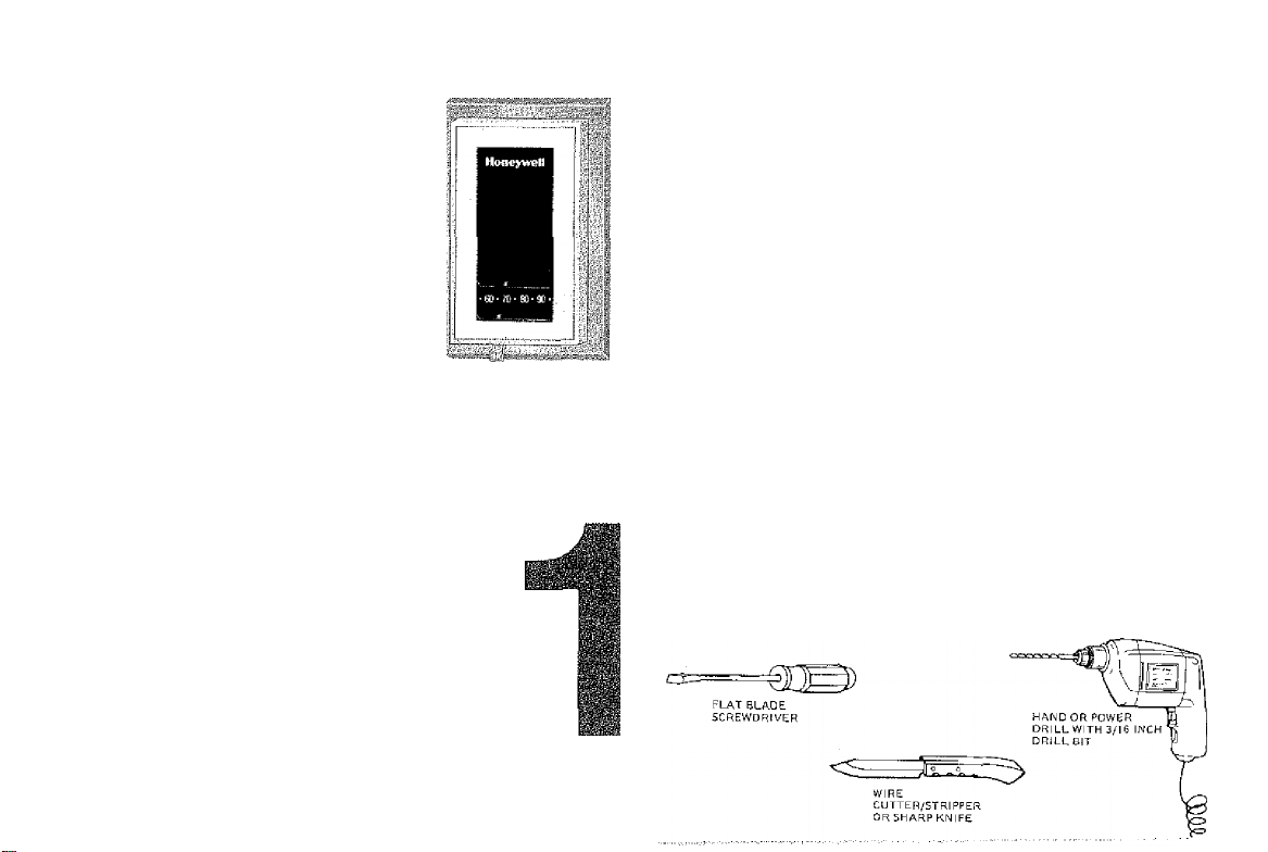
Assemble tools required,
□
as shown below.
PREPARATION
Page 2
CONTENTS
PREPARATION
THERMOSTAT FEATURES
REMOVING OLD THERMOSTAT
WIRE AND MOUNT NEW THERMOSTAT
CHECK OUT THE THERMOSTAT
THERMOSTAT SETTING
TROUBLESHOOTING
RECALIBRATE THERMOMETER
STEP
LIMITED ONE-YEAR WARRANTY
Hareywcii warrantE iiiis nrodiicl to tw Iroo ii&m dcFec!* in woikmarsiilj) at maiemi:
!«&m the dale of purchsge by Ihe consumer. II. at any lime diring ihe waicaiiiy pejitjg
rapAji or replace it |at Hpreyweii's gplion) williln a leasonable period of time.
II Ihe proauct Ic cisrociive,
a, leiLirn ii, with a bill dI sete, receipt, or olliDr dalird prool o< oirrchese, to tno dE
1
2
3
4
5
6
7
8
b. pacitjgp It oaiciuiiy, aioric with a bill ol sale, iece>pt, or other daiod pfooi g
naif It, poAiage prepaid, to Ihe lollowlng address:
HoneywelJ Inc.
Rolurnod Goods
894i Tenth AvonoQ North
Ti.is
lenty doss not cover removal or rolnstairaiiori tdgta. This warranty shall not apply II It Is shown oy Honeywell that ihe dafoci or
maifunciipr was oausad By damegewhich occarrod while the product wes In the possassiem ala consumer,
Honeywell's sole respocslblllly shell he to repair or replace the prpduot withir Iho larms listed above. HONEYWELL SHALL NOT BE LIABLE
Fon ANY LOSS Qf=l PAMAGE OF ANY KIND. IHCLuOinG ANY irvClDENTAL OR CONSEQUENTIAL DAMAGES RESULTING, ClHECTLV OR
INDIFteCTLV, From any breach of any warranty, express Oh IMPLIED. Qfl ANY OTHER FAILURE OF THIS PRODUCT. Sonic stales rtg
not Bilow the QXCluSian or llmitfttion or conaoquernicl damages, so this ilmlmtlpri may not apply to you.
THIS WARRANTY IS THE ONLY EXPRESS WARRANTY HONEYWELL MAKES ON THIS PRODUCT THE- DUHATiON QF ANY IMPLIED
WARRANTIES, INCLUDING THE WARRANTIES OF ME-HCHANTABILITY AND FITNESS FOR A PARTICULAR PURPOSE, IS HFBESY LIMIT50 TO
The one year OURATiON of this warranty, Soms Eiaies do not allow lirriiiations on how long an Implied warranty lasts, S6 ihe above
Jimitation may not apply ig you.
This warranty giuej ygu specific legel lights, and you may have otiiar rights which vary from giaie to stole.
If you have any quOsLons Dpagerning this warranty, please write ai-r Consumer Allalis uapariiTiant, Hcneyweli irg., tiiBS Douglas Drive Nonh,
Golden Valley, MN 55422-13D6 oi tail toliect Eit 6t2/W2-3300.
S.M.
9-85«
Ulnnaepolrs, tAN 55427-d37S
Printed in U.S.A.
ider normal use and seArlce, for a period oi ano ¡i) year
e product IS delobtlve or maflunciions, нопвулеП aha"
er pr contiBctor frotii which ybu purchased It, or
viroheae, and a short descfjpliDn ol the rrelljnciioa, an:
Form Number 69-0265
®Horisyv/Gll Inc, 1035
Make certain that your
burner/air conditioner
(where applicable) are working,
□
especially if they have been
inoperative for any length of
time. If either does not work,
contact your local heating/air
conditioning dealer. Do NOT
operate the air conditioning
system if outdoor temperature is
below 50 F [IOC],
Carefully unpack your
□
new thermostat
THERMOSTAT
FEATURES
Top
Mounting Hole
(thermostat to
wait or outlet
box)
Adjustable Heat
Anticipator
Setting Lever
(CT50A, CT51A,
CT52A only)
Mounting
Clips {for cover)
Fan Switch
fCT5l A only)
System Switch
(CT51A only)
Page 3

I i
SPIRIT LEVEL OR PLUMB BOB AMD LINE
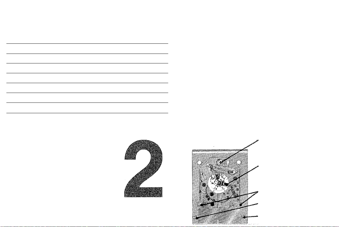
REMOVING OLD
THERMOSTAT
(See illustration under step
4 to help you recognize the
heat anticipator.) Make a note
Begin by turning off
power to the
heating/cooling system at
□
the main fuse panel. Most
residential systems have a
separate switch box or
circuit breaker for
disconnecting power to the
furnace.
Remove cover of old
thermostat—cover
normally snaps off when
□
pulled firmly from the
bottom. If it resists, check
for a screw that locks the
cover on.
For CT50A, CT51A,
or CT52A installation,
before removing the old
□
thermostat from the wall,
ook at it carefully to locate
the heat anticipator
adjustment mechanism.
(See last illustration under
step 4 to help you
recognize the heat
anticipator.) Make a note
here I I of that
anticipator setting for future
reference. The heat
anticipator pointer, if
adjustable, will be set at
one of a series of numbers
representing the (electrical)
current rating of the primary
control in your furnace. The
number will be one of the
following: .2, .4, .8, etc., or
0.2, 0.4, 0.8, etc. If no heat
anticipator/indication is
showing, do not be
concerned; move on to the
next step-
Loosen screws
holding thermostat
base to subbase or wall,
□
and lift away.
Disconnect wires
from old thermostat
□
^■1
or subbase, if your
thermostat has more than 2
wires, as you disconnect
each wire, tape the end and
label it with the letter of the
terminal designation to
make reconnection to new
thermostat easier. Take
care that these wires do not
fall back into the wall
opening.
Retain the old
thermostat for
reference purposes until
□
your new thermostat is
functioning smoothly.
Page 4

WIRE AND
MOUNT
THERMOSTAT
For CT5QA'.
Connect each wire from the wall
to either terminal on the back of the
□
thermostat. Tighten the screws.
For CT51A, CT52A;
Connect wires from the wail to
matching terminals on back of thermo
□
stat. Tighten the screws.
For GT53A:
Connect vi/ires to R and W for
7S0 mV systems. Connect to R and Y
□
for 250 or 500 mV systems. Tighten the
screws.
Push excess wire back into wait
and plug hole with nonilammable
insulation to prevent drafts from affecting
□
thermostat operation.
Place a bubble level or plumb line against the ther
mostat to find the level position. Start a screw in
the center of the bottom mounting hole. Move the temper
□
ature setting lever if necessary to uncover the niounting
hole.
Page 5

CT53
jncfi
3^1
WIRE AND MOUNT THERMOSTAT (continued)
Recheck for level position
ing, and firmly tighten both
mounting screws.
□
If installing CT50A, CT51 A,
or CT52A, make sure you
have the current (anticipator
□
setting) for your system. This is
the number you wrote in the box
in step 3. If you were unable to
find the current draw for step 3,
this information can be found
printed on the primary control at
the furnace. The primary control
is usually a gas valve, zone valve,
or a relay or burner control box
with the thermostat wires con
nected to it.
OIL BURNER CONTROL
CHECKOUT
THE
THERMOSTAT
On the CT51A, the system
switch controls as follows:
HEAT—heating system only
□
operates.
. OFF—heating and cooling sys
tems are disconnected.
COOL—cooling system only
operates.
The fan switch controls as
follows:
AUTO—fan operates when
heating or cooling system,
operates.
ON—fan operates continu
ously.
NOTE: In the following instruction,
disregard heating or cooling
directions if not applicable to
your system.
Turn on power to the
heating/cooling system.
□
Observe system operation
for at least one cycle on
both heating and cooling. To
□
observe:
Place the system switch
at HEAT position and fan
switch at AUTO. More the temper
□
ature setting lever 10 F [5.6 C]
above room temperature. The
heating equipment should turn
on, A short warm-up period may
be required before the system
fan turns on.
Place system switch at
COOL position and move
temperature setting lever 10 F
□
[5.6 C[ below room temperature.
The cooling equiprnent should
turn on and the system fan should
turn on,
NOTE: Some systems have a time
delay that can prevent opera
tion up to 30 seconds.
Turn the fan switch to ON.
The system fan should turn
on, and operate continuously.
□
The system blower should con
tinue to operate at any system
switch or thermostat setting.
(See ill
4 to hf
heat a|
On the CT50A, CT51A, or
CT52A, set heat anticipator
indicator at rating printed on
□
primary control.
Press the thermostat cover
firmly onto the mounting
THERMOSTAT
SETTING
On CT51A, place the sys
tem and fan switches at
the desired settings for operation.
□
On all models, move the
temperature setting lever
to the desired temperature com
□
fort level.
Page 6

TROUBLESHOOTING
Your Honeywell Miermostat requires little or no attention. Most problems can generally be traced to tbe following:
NOTE: [f your system is heating-only or cooling-only, disregard sections not applicable to your system.
SYMPTOM
No heat
Furnace turns on
and off.
Major swings in
temperature is too long. cover and move the heat
(greater than 2 F
[1.1C] when outside temperature mark. Wait several hours
stable).
PROBLEM
System switch at OFF or
COOL Position.
Blown fuse or tripped Replace fuse or reset
circuit breaker.
Furnace power switch is Switch to ON.
on OFF.
No pilot flame.
Improper connections to
thermostat.
Defective thermostat. Exchange the thermostat No cooling.
(Here’s how you tell: Turn (see Warranty).
power to furnace OFF.
Then remove the thermostat from the wall. Disconnect wire from W
terminal. Turn power to
lurnace ON. Touch W
wire to R terminal. The
thermostat is defective if
the burner comes on.)
Other.
Burner-on period Is too
short.
Burner-on period
CORRECTIVE ACTION SYMPTOM
circuit breaker.
Relight pilot flame per
furnace manufacturer’s
instructions.
With Power to furnace
OFF, tighten all mounting
and terminal screws. Repair broken wires.
Contact service technician
for assistance.
Ftemove the thermostat
cover and move the heat
anticipator lever COUNTERCLOCKWISE V_>
one scale mark. Wait at
least several hours to stabilize.
Remove the thermostat
anticipator lever CLOCKWISE
_____
for the system to stabilize.
Move switch to HEAT Thermostat setting
J one scale
position. and thermometer
reading disagree.
PROBLEM
Thermostat is not level.
Thermostat affected by Contact service technician
drafts or radiant heat. to change 'ihe location. The
Thermostat is out of call- Contact a qualified service
bration.
Thermometer is out of Recalibrate, See step 8.
calibration.
System switch in in OFF Move switch to COOL
or HEAT position. position.
Blown fuse or tripped
circuit breaker.
Condenser switch (located outdoors) is turned tion.
OFF.
Improper connections to
thermostat.
Detective thermostat. Exchange the thermostat.
(Here’s how you tell: Turn See Warranty.
power to cooling system
OFF. Then remove the
thermostat from wall.
Disconnect wire from Y
terminal. Turn power to
cooling system ON.
Touch Y wire to terminal
R. The therrmostat is defective if the compressor
starts. Some systems
have a time delay, so
allow at least 2-3
minutes.)
Other.
CORRECTIVE ACTION
Recheck the thermostat
position on wall. Use a
bubble level to make sure
it's level. See step 4.
thermostat should be about
5 ft [1.5 m] above the floor
and on an inside wall.
technician to recalibrate
the thermostat.
Replace fuse or reset
circuit breaker.
Move switch to ON post-
With pOvV6r to furosc©
OFF, tighten all mounting
and terminal screws. Repair broken wires.
Contact service techniclan for assistance.
RECALIBRATE THERMOMETER
If the thermostat set point and the
thermometer reading do not agree, the
thermometer may need recalibration.
Follow the procedure below.
Remove thermostat cover.
Set the cover on a table near an
accurate thermometer.
After allowing 5 or 10 minutes for
stabilization, compare the read-
!ngs.
If the readings are the same,
replace cover and put the system
into operation.
□
If the readings are different, insert
a hex-head wrench in the ther
mometer shaft and turn it until the
□
thermometers have the same reading.
Replace cover and put the system
nto operation.
□
 Loading...