

Page 1
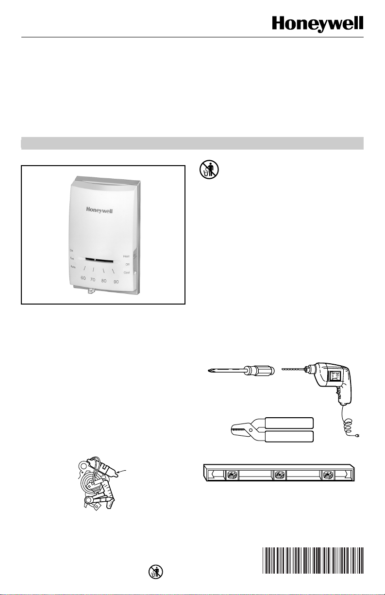
Heating/Cooling Thermostat
Y
T
S
Heating/Cooling
15 to 30 Vac Thermostat
Congratulations on the purchase of your new thermostat!
CT41A
INSTALLATION INSTRUCTIONS
MERCURY NOTICE
If this control is replacing a control that contains
mercury in a sealed tube, do not place your old
control in the trash. Dispose of it properly.
Contact your local waste management authority
for instructions regarding recycling and the
proper disposal of an old control.
1 PREPARE FOR INSTALLATION
If you are unsure about wiring procedures, please call a
qualified service technician for assistance.
❑ To correctly install your new thermostat, follow these
step-by-step instructions. It is recommended that, as
you read, understand, and complete each step, you
place a check mark in each box provided.
❑ See Your New CT41A Thermostat section above to
determine the thermostat suitability for compatibility
with your home system. If not, return it to the retailer.
Acquire the required installation tools and supplies, as
needed. See Fig. 1.
YOUR NEW CT41A THERMOSTAT
Your new CT41A Thermostat replaces most 15 to 30V,
4-wire, heating/cooling system thermostats. The CT41A
is suitable for gas or oil heat or electric air conditioning
systems.
Direct questions about this thermostat to our Web site at
www.honeywell.com/yourhome or call the customer
information line at 1-800-468-1502.
MERCUR
SWITCH
YPICAL LOCATION OF A MERCURY
WITCH IN A THERMOSTAT
® U.S. Registered Trademark
Copyright © 2003 Honeywell International Inc • • All Rights
M10614
SCREWDRIVER
WIRE CUTTER/STRIPPER IF NEEDED TO STRIP WIRES
LEVEL, IF NEEDED TO LEVEL
THERMOSTAT FOR APPEARANCE
Fig. 1. Required installation tools/supplies.
HAND OR POWER
DRILL WITH 3/16 INCH
DRILL BIT, IF NEEDED TO
DRILL HOLES IN WALL
69-0788-2
M20551
Page 2
CT41A HEATING/COOLING THERMOSTAT
H
2 REMOVE OLD THERMOSTAT
❑ Test to be sure your heating and air conditioning
systems (where applicable) are working correctly. If
not, contact your local heating/air conditioning dealer.
To avoid compressor damage, do not operate the
cooling system when outdoor temperature is below
50°F (10°C).
CAUTION
Equipment Damage Hazard.
Handling wires during installation can
damage equipment.
Disconnect power at furnace or main breaker/
fuse box before beginning installation.
❑ Carefully unpack your new thermostat and save the
package of screws, the instructions and the receipt.
❑ Remove the cover from the old thermostat. If it does
not snap off when pulled firmly from the bottom, check
for a screw that locks on the cover.
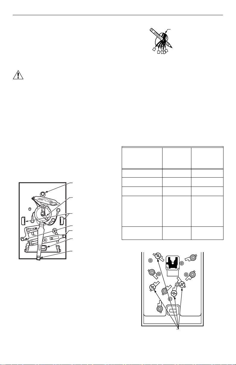
❑ Before removing the old thermostat from the wall, look
at it carefully to locate the heat anticipator adjustment
mechanism, see Fig. 2. Make a note here ________
of the anticipator setting for future reference. The heat
anticipator pointer, if adjustable, is set at one of a
series of numbers representing the (electrical) current
rating of the primary control of your system (in
amperes). The numbers range from 0.18 to 1.0. If no
heat anticipator/indication is showing, do not be
concerned; move on to the next step.
TOP MOUNTING HOLE
(THERMOSTAT TO WALL
OR OUTLET BOX)
ADJUSTABLE HEAT
ANTICIPATOR
.18
.9
.2
.7
.5
.25
3
Fig. 2. Locating heat anticipator adjustment
❑ Loosen screws holding thermostat to subbase,
wallplate or wall and lift away.
❑ Disconnect wires from old thermostat or subbase. As
you disconnect each wire, tape the end and label it
with the letter of the terminal designation. If there are
only two wires, they do not require labeling. Wrap
wires around a pencil to keep them from falling back
into the wall as shown in Fig. 3.
mechanism.
SETTING LEVER
MOUNTING CLIPS
(FOR COVER)
FAN SWITCH
SYSTEM SWITCH
BOTTOM
MOUNTING HOLE
TEMPERATURE
SETTING LEVER
M3782A
WIRES THROUG
WALL OPENING
M5136
Fig. 3. Wrapping wires around pencil.
❑ Keep the old thermostat for reference until your new
thermostat is functioning smoothly.
3 WIRE AND MOUNT THERMOSTAT
❑ Connect wires from the wall to the matching terminals
on the back of the thermostat. See Fig. 4. Tighten the
screws.
NOTE: If terminal designations on old thermostat do not
match those on new thermostat, see Table 1.
Table 1. Terminal Functions.
New
Old Thermostat
Terminal Marking Function
G or F Fan G
Y or C or M or Y
W or H or W
1
Cooling Y
1
Heating W
RC, V, VC or B Power Your 5-wire
RH, M, VR, 4, A or RPower R
W
Y
Thermostat
system cannot
use this
thermostat;
use a CT87B
instead.
R
G
Ter mina l
Marking
69-0788-2 2
TERMINAL SCREWS
Fig. 4. Connect wires from wall to thermostat
matching terminals.
M8067A
Page 3
❑ Push excess wire back into wall and plug hole with
M3774
T
F
F
4
R
nonflammable insulation to prevent drafts from
affecting thermostat operation.
❑ Remove thermostat cover by pulling outward on right
edge of cover until it snaps free of the thermostat
base.
❑ Fasten thermostat to wall or vertical outlet box with a
screw through the top mounting hole. See Fig. 2 for
hole location.
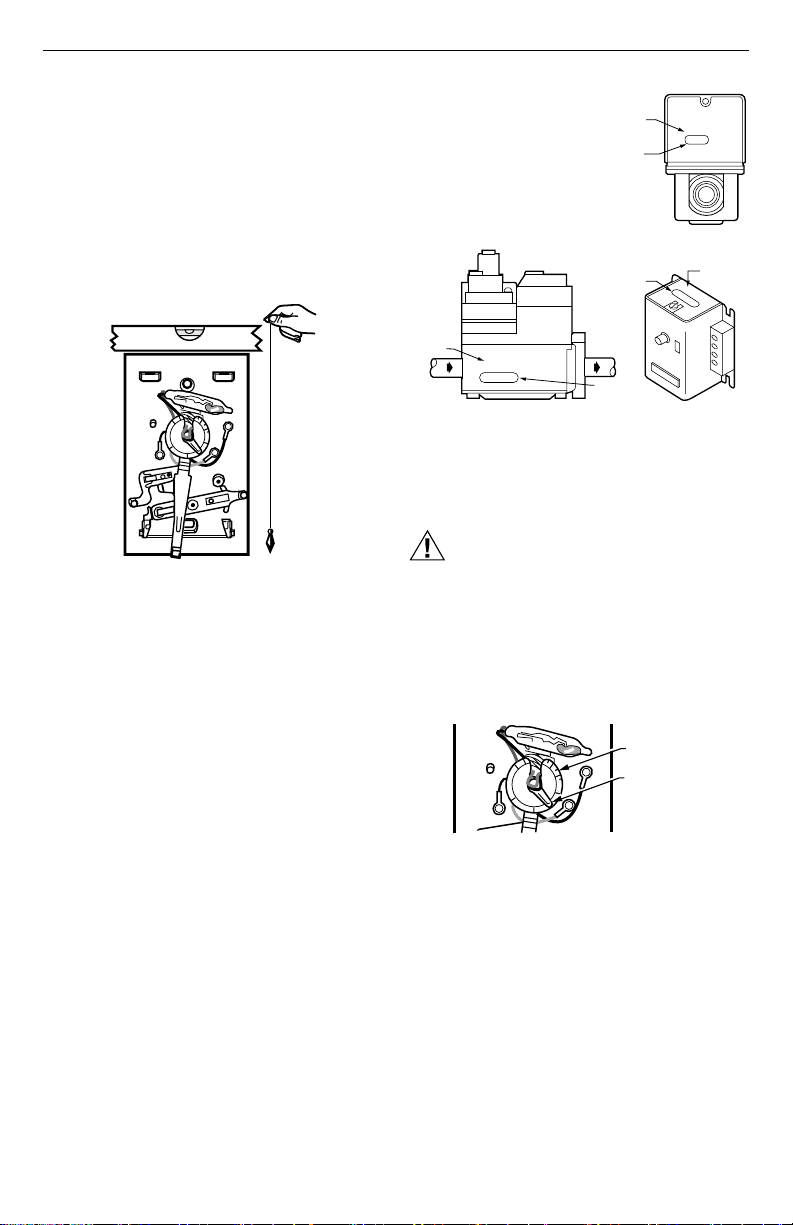
❑ Place a bubble level or plumb line against the
thermostat to find the level position. See Fig. 5. Start a
screw in the center of the bottom mounting hole.
(Move the temperature setting lever, if necessary, to
uncover the mounting hole.)
BUBBLE LEVEL
.18
.9
.2
.7
.5
.25
3
PLUMB
LINE
PLUMB
BOB OR
WEIGH
Fig. 5. Level thermostat.
❑ Recheck for level positioning and firmly tighten both
mounting screws.
❑ Be sure you have the current draw anticipator setting
for your system. This is the number you wrote in the
box in step 2 Remove Old Thermostat section. If you
could not find the current draw for step 2, look on your
primary control at the furnace. See Fig. 6. (The
primary control is usually a gas valve, zone valve, or a
relay or burner control box with the thermostat wires
connected to it. For electric heat, add the fan relay
current, usually 0.2A to 0.4A.)
CT41A HEATING/COOLING THERMOSTAT
SHOWS
VOLTAGE
8406
RATING
SHOWS
ANTICIPATOR
SETTING
SHOWS
CURRENT
DRAW
SHOWS
VOLTAGE
RATING
ROM MAIN
UEL SUPPLY
24 Vac 50/60 Hz
0.4 AMP
TYPICAL GAS VALVE
Fig. 6. Locate your system current draw anticipator
❑ Set the heat anticipator indicator at the rating printed
on the primary control. See Fig. 7.
setting.
TO
BURNER
SHOWS
ANTICIPATOR
SETTING
V8043E 1004 4
24V 50/60CY
@ 60CY
.32 AMP
ZONE VALVE
OIL BURNER CONTROL
0.2 AMP
30 VAC
SHOWS
VOLTAGE
RATING
M6116B
T
T
F
F
CAUTION
Heat Anticipator Hazard.
Setting heat anticipator too low can cause
anticipator burnout.
Set heat anticipator at recommended rating to
avoid shorting out your valve or control and
prevent burnout of your heat anticipator.
.18
.9
.2
.7
.5
.25
3
SCALEPLATE
ADJUSTABLE
HEAT
ANTICIPATOR
SETTING LEVE
M378
Fig. 7. Set heat anticipator indicator to match your
❑ Press thermostat cover firmly onto the mounting clips.
See Fig. 2.
3 69-0788-2
primary control rating.
Page 4

CT41A HEATING/COOLING THERMOSTAT
4 CHECK OUT THERMOSTAT
The System switch controls as follows:
Heat: heating system only operates.
Off: heating and air conditioning systems are discon-
nected.
Cool: air conditioning system only operates.
The Fan switch controls as follows:
Auto: fan operates when heating or air conditioning
system operates.
On: fan operates continuously.
NOTE: In the following instructions, disregard heating
or air conditioning directions if not applicable to
your system.
CAUTION
Compressor Damage Hazard.
Operating at too low of an outdoor
temperature can cause compressor damage.
Do not operate cooling if outdoor temperature is
below 50°F (10°C).
Allow compressor to remain off for five minutes
before restarting.
Refer to manufacturer’s recommendations.
❑ Turn on power to the heating/air conditioning system.
❑ Observe system operation for at least one cycle on
both heating and air conditioning. To observe:
❑ Place the System switch at the Heat position and the
Fan switch at the Auto position. Move the temperature
setting lever 10°F (6°C) below room temperature. The
heating equipment should turn on. A short warmup
period may be required before system fan turns on.
NOTE: Some systems have a time delay that can pre-
vent operation up to five minutes.
❑ Turn the Fan switch to On. The system fan should turn
on and operate continuously. The system blower
should continue to operate at any System switch or
thermostat setting.
5 THERMOSTAT
❑ Place the System and Fan switches at the desired
settings for operation.
6 TROUBLESHOOTING (TABLE 2)
Your Honeywell thermostat requires little or no attention.
Most problems can be resolved according to Table 2.
NOTE: If your system is heating-only or air
conditioning-only, disregard sections not
applicable to your system.
69-0788-2 4
Page 5

CT41A HEATING/COOLING THERMOSTAT
Table 2. Recommended Corrective Action for Your System.
Symptom Problem Corrective Action
No heat System switch is at Off of Cool position. Move System switch to Heat position.
Blown fuse or tripped circuit breaker. Replace fuse or reset circuit breaker.
Furnace power switch is at Off. Turn furnace power switch to On.
Furnace turns on and
off.
Major swings in
temperature greater
than 2°F (1°C) when
outside temperature is
stable.
Thermostat setting and
thermometer reading
disagree.
No pilot flame. Relight pilot flame according to furnace
Incorrect connections to thermostat. With power to furnace at Off, tighten all
Other. Contact a qualified service technician for
Burner On period is too short. Remove the thermostat cover and move the
Burner On period is too long. Remove the thermostat cover and move the
Thermostat is not level. Recheck the thermostat position on the wall.
Thermostat is affected by drafts or radiant
heat.
manufacturer instructions.
mounting and terminal screws. Repair frayed or
broken wires.
assistance.
heat anticipator lever counterclockwise (left)
one scale mark. Replace the cover and wait
several hours for the system to stabilize.
heat anticipator lever clockwise (right) one
scale mark. Replace the cover and wait several
hours for the system to stabilize.
Use bubble level to make sure it is level. See
step 3 and Fig. 5.
Contact a qualified service technician to change
the location.
Thermometer is out-of-calibration. Recalibrate. See step 7.
No air conditioning. System switch is in Off or Heat position. Move switch to Cool position.
Blown fuse or tripped circuit breaker. Replace fuse or reset circuit breaker.
Compressor switch (located outdoors) is
turned off.
Incorrect connections to thermostat. With power to system off, tighten all mounting
Move switch to On position.
and terminal screws. Repair broken wires.
Other. Contact service technician for assistance.
5 69-0788-2
Page 6

CT41A HEATING/COOLING THERMOSTAT
M
R
7 RECALIBRATE THERMOMETER
If the thermostat setpoint and the thermometer reading
do not agree, the thermometer may need recalibration.
Follow this procedure:
❑ Remove thermostat cover.
❑ Set the cover on a table near an accurate
thermometer.
❑ After allowing five or ten minutes for stabilization,
compare the readings.
❑ If the readings are the same, replace the cover and
put the system into operation.
❑ If the readings are different, insert a hex head wrench
into the thermostat shaft and turn it until the
thermometers have the same reading. See Fig. 8.
❑ Replace cover and put the system into operation.
BACKSIDE
OF COVER
THERMOMETE
SHAFT
HEX HEAD
8068
WRENCH
Fig. 8. Adjusting thermometer calibration.
69-0788-2 6
Page 7

CT41A HEATING/COOLING THERMOSTAT
Limited One-Year Warranty
Honeywell warrants this product, excluding battery, to be free from defects in the workmanship or materials, under normal use and service, for a period of
one (1) year from the date of purchase by the consumer. If, at any time during the warranty period, the product is defective or malfunctions, Honeywell shall
repair or replace it (at Honeywel l’s option) within a reasonable period of time.
If the product is defective,
(i) return it, with a bill of sale or other dated proof of purchase, to the retailer from which you purchased it, or
(ii) package it carefully, along with proof of purchase (including date of purchase) and a short description of the malfunction, and mail it, postage prepaid,
to the following address:
Honeywell Return Goods Canada: Honeywell Limited/Honeywell Limitée
Dock 4, MN10-3860 Product Services ON15
1885 Douglas Dr N 35 Dynamic Dr
Golden Valley, MN 55422 Scarborough, Ontario M1V 4Z9
This warranty does not cover removal or reinstallation costs. This warranty shall not apply if it is shown by Honeywell that the defect or malfunction was
caused by damage which occurred while the product was in the possession of a consumer.
Honeywell’s sole responsibility sh all be to repair or replace the produ ct within the terms stated above. H ONEYWELL SHALL NOT BE LIABLE FOR ANY
LOSS OR DAMAGE OF ANY KIND, INCLUDING ANY INCIDENTAL OR CONSEQUENTIAL DAMAGES RESULTING, DIRECTLY OR INDIRECTLY,
FROM ANY BREACH OF ANY WARRANTY, EXPRESS OR IMPLIED, OR ANY OTHER FAILURE OF THIS PRODUCT. Some states do not allow the
exclusion or limitation of incidental or consequential damages, so this limitation may not apply to you.
THIS WARRANTY IS THE ONLY EXPRESS WARRANTY HONEYWELL MAKES ON THIS PRODUCT. THE DURATION OF ANY IMPLIED
WARRANTIES, INCLUDING THE WARRANTIES OF MERCHANTABILITY AND FITNESS FOR A PARTICULAR PURPOSE, IS HEREBY LIMITED TO
THE ONE YEAR DURATION OF THIS WARRANTY. Some states do not allow limitations on how long an implied warranty lasts, so the above limitation
may not apply to you.
This warranty gives you specific legal rights, and you may have other rights which vary from state to state.
If you have any questions concerning this warranty, please write Honeywell Customer Relations, 1985 Douglas Dr N, MN10-1461, Golden Valley, MN
55422. In Canada, write Retail Products ON15, Honeywell Limited/Honeywell Limitée, 35 Dynamic Dr, Scarborough, Ontario M1V 4Z9.
7 69-0788-2
Page 8

CT41A HEATING/COOLING THERMOSTAT
Automation and Control Solutions
Honeywell International Inc. Honeywell L imited-Honeywell Limitée
1985 Douglas Drive North 35 Dynamic Drive
Golden Valley, MN 55422 Scarborough, Ontario
69-0788—2 G.H. Rev. 10-03 www.honeywell.com/yourhome
M1V 4Z9
Printed in U.S.A. on recycled
paper containing at least 10%
post-consumer paper fibers.
 Loading...