

Page 1
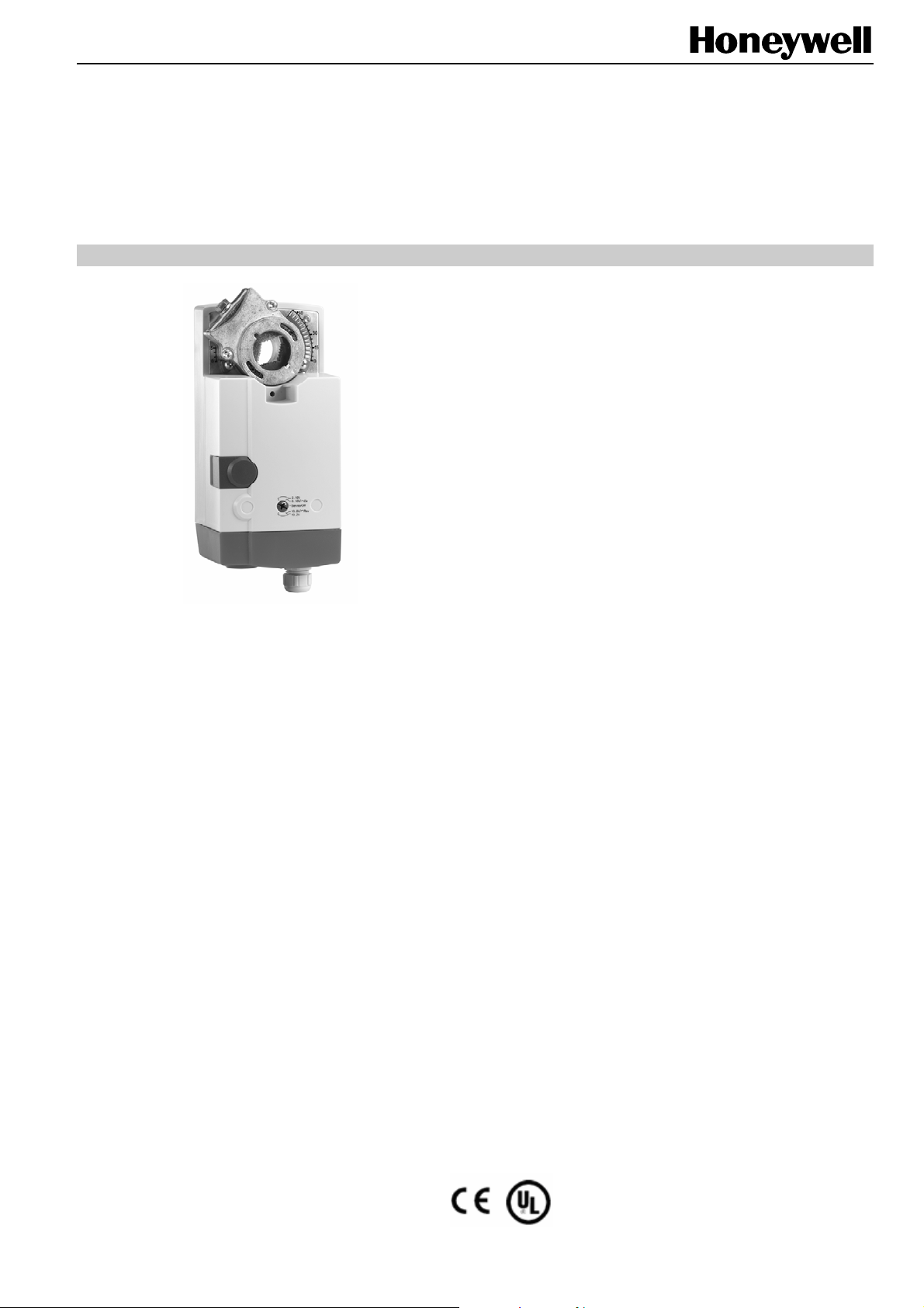
CN20, CN34 SERIES
NON-SPRING RETURN DIRECT-COUPLED DAMPER ACTUATORS
FOR MODULATING AND FLOATING / 2-POSITION CONTROL
PRODUCT DATA
SPECIFICATIONS
Supply voltage 24 Vac/dc ±15%, 50/60 Hz;
Nominal voltage 24 Vac/dc, 50/60 Hz;
All values stated hereinafter apply to operation under
nominal voltage conditions.
Power consumption
CN7220A2007 6 VA / 3 W
CN7234A2008 6 VA / 3 W
Ambient limits
Ambient operating limits -20...+60 °C (-5...+140 °F)
Ambient storage limits -40...+80 °C (-40...+175 °F)
Relative humidity 5...95%, non-condensing
Safety
Protection standard IP54 as per EN 60529
Protection class II as per EN 60730-1
Overvoltage category II
GENERAL
These direct-coupled damper actuators provide modulating
control for:
• air dampers,
• VAV units,
• air handling units,
• ventilation flaps,
• louvers, and
• reliable control for air damper applications with up to
2
4.6 m
/ 50 sq.ft. (20 Nm / 177 lb-in) or 7.8 m2 / 85 sq. ft.
(34 Nm / 300 lb-in) (seal-less dampers; air frictiondependent).
FEATURES
• Self-centering shaft adapter
• Access cover to facilitate connectivity
• Service/off for safe & easy servicing
• Rotation direction selectable by switch
• Declutch for manual adjustment
• Mechanical end limits
• Field-installable auxiliary switches
• Mountable in any orientation (no IP54 if upside down)
• Mechanical position indicator
• CE and UL certified
Lifetime
Full strokes 60000
Repositions 1.5 million
Mounting
Round damper shaft 10...27 mm (3/8...1-1/16")
Square damper shaft 10...18 mm (3/8...11/16");
45° steps
Shaft length min. 22 mm (7/8")
Control signal 0(2)...10 Vdc
0(4)...20 mA
Input impedance >100 kΩ [0...10 V]
500 Ω [0...20 mA]
Feedback signal
Limits ± 1 mA at 0...10 V
End switches (when included)
Rating 5 A (resistive) / 3 A (inductive)
Triggering points 5° / 85°
Torque rating
CN7220A2007 20 Nm (177 lb-in)
CN7234A2008 34 Nm (300 lb-in)
Runtime 95 sec (60 Hz) / 110 sec (50 Hz
or DC supply)
Rotation stroke 95° ± 3°
Dimensions see "Dimensions" on page 8
Weight (without cables) 1.35 kg (3 lbs.)
Noise rating 40 dB(A) max. at 1 m
Certification CE & UL
® U.S. Registered Trademark EN0B-0341CH33 R0803A
Copyright © 2008 Honeywell Inc. • All rights reserved
Page 2
CN20, CN34 SERIES DAMPER ACTUATOR FOR MODULATING AND FLOATING CONTROL
MODELS
Model # Description
CN7220A2007
CN7234A2008
20Nm,24Vac/Vdc, Modulating and floating/2-position control, Non-Spring return, Voltage Feedback
Signal and without aux. Switch
34Nm,24Vac/Vdc, Modulating and floating/2-position control, Non-Spring return, Voltage Feedback
Signal and without aux. Switch
PRODUCT IDENTIFICATION SYSTEM
C – Direct Coupled Actuator
N – Fail Safe Function (Non-Spring Return)
61 – 24V Floating/2-position Control
72 – 24V Modulating and Floating/2-position Control
46 – 230V Floating/2-position Control
20 – 20 Nm (177 lb-in)
34 – 34 Nm (300 lb-in)
A – Standard Model
1 – No Feedback
2 – Voltage Feedback Signal
0 – No Internal Auxiliary Switches
2 – Two Internal Auxiliary Switches
XX – System Controlled Numbers
C N 72 20 A 2 0 XX
Fig.1. Product Identification System
OPERATION / FUNCTIONS
1
2
3
4
5
6
7 8
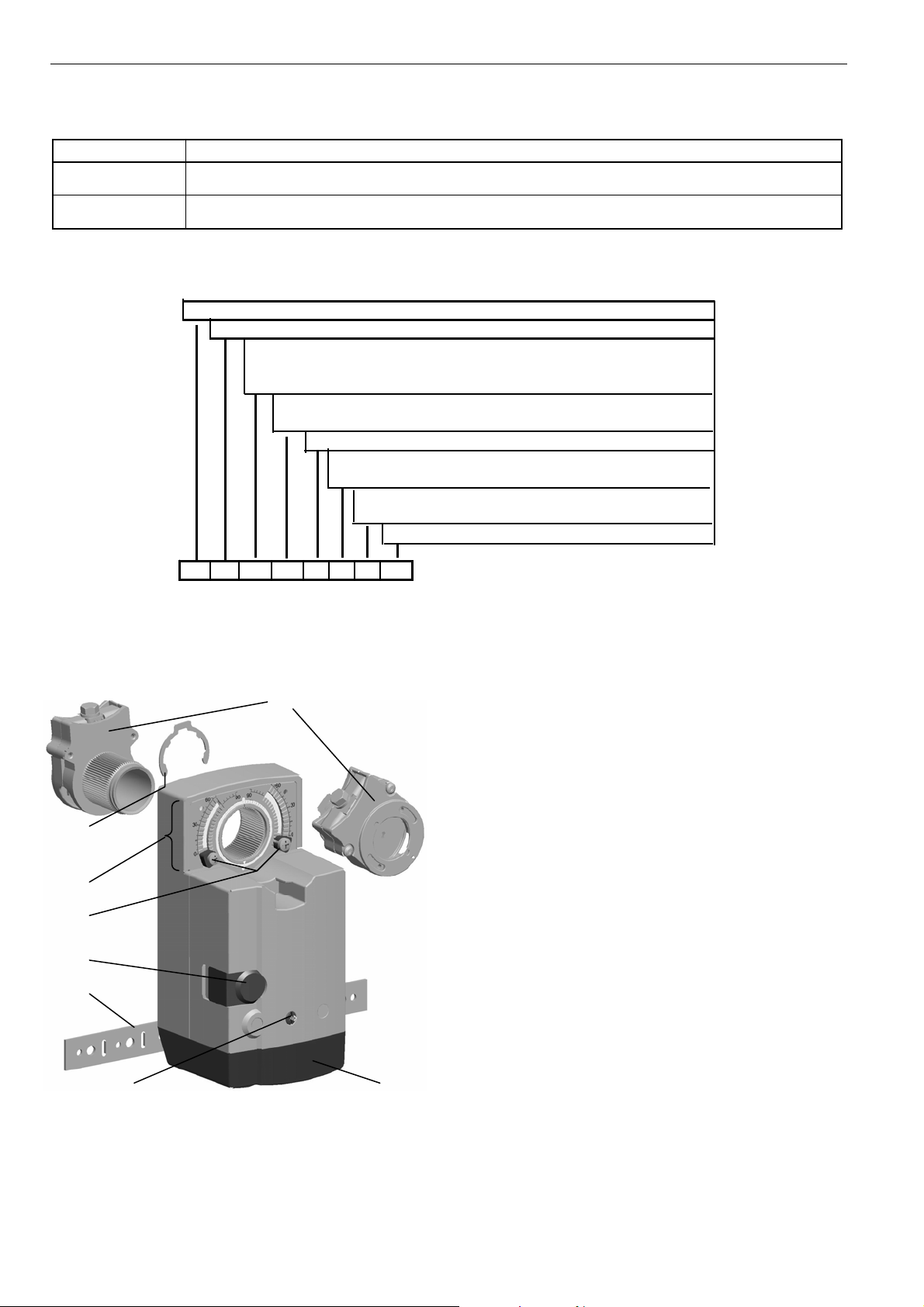
Fig. 2. Setting units and control elements
Legend for Fig.2:
1 Self-centering shaft adapter
2 Retainer clip
3 Rotational angle scales (0...90° / 90...0°)
4 Mechanical end limits
5 Declutch button
6 Anti-rotation bracket
7 Function Selection Switch
8 Access cover
Contents of Package
The delivery package includes the actuator itself, parts 1
through 8 (see Fig.2), the anti-rotation bracket screws, and
installation instruction.
RUN MODES
The function selection switch (see Fig 3) is used to place the
actuator into any one of five different modes:
• 2-10V, modulating control; floating/2-position control, cw
run
• 0-10V/Dir, modulating control; floating/2-position control,
cw run
• Service/Off, actuator stop running
• 10-0V/Rev, modulating control; floating/2-position control,
ccw run
EN0B-0341CH33 R0803A 2
Page 3

CN20, CN34 SERIES DAMPER ACTUATOR FOR MODULATING AND FLOATING CONTROL
• 10-2V, modulating control; floating/2-position control, ccw
run
Fig.3. Function selection switch
Power-Off Behavior
If power is removed, the actuator retains its position.
Service/Off
If the function selection switch is set to the "Service/Off"
position, all rotary movement is cancelled, and all control
signals are ignored, thus allowing the actuator to be safely
manually operated.
Floating/2-Position Run Mode
If the function selection switch has been set to one of the four
positions (2-10V, 0-10V/Dir, 10-0V/Rev, 10-2V) – and the
actuator is wired as Floating/2-position mode (see A2 and A3)
– then as soon as operating power is applied, the actuator will
run clockwise or counterclockwise.
Table 1. Shaft adapter behavior in the floating mode
Control signal at Function selection switch settings
Terminal 3 Terminal 4 2...10V 0...10V /Dir Service / Off 10...0V /Rev 10...2 V
open open stops stops stops stops stops
open 24 Vac/dc CCW CCW stops CW CW
24 Vac/dc open CW CW stops CCW CCW
Table 2. Shaft adapter behavior in the 2-position mode
Control signal at Function selection switch settings
Terminal 3 Terminal 4 2...10V 0...10V /Dir Service / Off 10...0V /Rev 10...2 V
24 Vac/dc open CW CW stops CCW CCW
24 Vac/dc 24 Vac/dc CCW CCW stops CW CW
Table 3. Shaft adapter behavior in the modulating mode
Control signal at Function selection switch settings
Terminal 3 Terminal 4 2...10V 0...10V /Dir Service / Off 0...10V /Rev 10...2 V
Open
< min. control signal plus 0.24V
between min. control signal plus 0.24V
and max. control signal minus 0.24V
> max. control signal minus 0.24V
open -- -- stop -- --
24 Vac/dc
open -- -- stop -- --
24 Vac/dc
open proportional proportional stop proportional proportional
24 Vac/dc
open -- -- stop -- --
24 Vac/dc
Modulating Run Mode
If the function selection switch has been set to one of the four
positions (2-10V, 0-10V/Dir, 10-0V/Rev, 10-2V) – and the
actuator is wired as modulating mode (see A1) – as soon as
operating power is applied, the actuator will run according to
the control signals applied. If terminal 5 is also wired, the
actuator will output the voltage feedback signal(0/2-10V)
proportional to actuator’s actual position. Alternatively, if
terminal 4 is wired and powered on, actuator will override the
control signal and immediately come to a position of 0% of
max. stroke.
Table 1 describes the actuator behavior (stops, rotates CCW,
or rotates CW) for the floating mode in relation to the control
signals applied to terminals 3 and 4 and to the function
selection switch setting.
Table 2 describes the actuator behavior (stops, rotates CCW,
or rotates CW) for the 2-position mode in relation to the
control signals applied to terminals 3 and 4 and to the function
selection switch setting.
Table 3 describes the actuator behavior (stops, rotates CCW,
rotates CW, runs in proportional position, or runs to 0% of
max. stroke) for the modulating mode in relation to the control
signals applied to terminals 3 and 4 and to the function
selection switch setting.
0% (most
left)
0% (most
left)
0% (most
left)
0% (most
left)
0% (most
left)
0% (most
left)
0% (most
left)
0% (most
left)
stop
stop
stop
stop
0%(most
right)
0%(most
right)
0%(most
right)
0%(most
right)
0% (most
right)
0% (most
right)
0% (most
right)
0% (most
right)
3 EN0B-0341CH33 R0803A
Page 4

CN20, CN34 SERIES DAMPER ACTUATOR FOR MODULATING AND FLOATING CONTROL
Adaption will be carried out only when:
100
50
0
final position of shaft adapter (% of max. stroke)
upper dead band (9.76 to 10.0 V)
range of proportional
actuator movement
(0.24 to 9.76 V)
lower dead band (0 to 0.24 V)
00.24
control signal (V)
5.0 10.09.76
Fig.4. Final actuator position in dependence upon control
signal (example selection setting of 0...10 V)
• Modulating models only, such as CN7220A2007,
CN7234A2008, etc,
• actuator is wired in modulating mode (see Fig. A1)
• the control signal’s value rises up into the upper dead
band (i.e to more than the max. control signal minus
0.14V) or drops down into the lower dead band (i.e to less
than the min. control signal plus 0.14V), and if the shaft
adapter can remain at the respective (upper or lower)
mechanical end limit at least 3 seconds, the actuator will
recognize the new position automatically, and autoadaption is happened (see Fig. 4).
Sleep Mode
When actuator reaches end stop or any obstacles blocking its
running, it will fall into sleep mode automatically. Actuator will
periodically start up and try to resume running, which will save
energy significantly through whole service life.
Overriding
100
50
An override is a condition in which a 24 V signal is applied to
terminal 4 of an actuator in the modulating mode, thus
causing the actuator to ignore the control signal at terminal 3,
whereupon it will instead move to a position of 0% of its
maximum stroke. It would be the most left side [0/2~10V
mode] or most right side [10~0/2 V mode] (see Table 3).
Feedback
If correspondingly wired (see A1), the actuator provides, via
terminal 5, a feedback signal(0/2~10V) proportional to the
actual position of the actuator (see Fig. 5).
0
current position of shaft adapter (% of max. stroke)
0
5
feedback signal (V)
10
Fig.5. Feedback signal in dependence upon current
position of actuator (example selection switch setting o f
0...10 V)
Dip Switches
The actuator is equipped with two dip switches (only switch 1
selectable) accessible after removing the access cover (see
Fig. 7).
Adaption
Adaption is a function in which the actuator re-maps its feedback signal and control signal in accordance with repositioned
mechanical end limits (see Fig.6) and thus recognizes their
new positions.
100
(before)
n
o
i
t
p
a
d
a
r
ion
t
ap
ad
e
r
o
control signal (volts)
new position of UPPER
mechanical end limit
new position of LOWER
mechanical end limit
100
(after)
final position of
e
t
f
a
actuator (% of max.)
0
(after)
ef
b
0
(before)
0 10.0
Fig.6. Adaption (selection switch set to "0...10 V")
EN0B-0341CH33 R0803A 4
95
final position of actuator (degrees)
0
1 2
O
N
1 2
O
N
1: (U) VOLTAGE CONTROL
2: RESERVED
Fig.7. Dip switches (view with PCB at bottom)
1 2
O
N
1: (mA) CURRENT
2: RESERVED
Page 5

CN20, CN34 SERIES DAMPER ACTUATOR FOR MODULATING AND FLOATING CONTROL
8580
590092.551015
Voltage/Current Control Signal Selection Dip Switch
In its default shipping position, the voltage/current control
signal dip switch (see Fig. 7) is set to OFF (= voltage control).
as shown in Fig. 7. Setting it to ON results in current control
4…20mA.
Position Indication
The hub adapter indicates the rotation angle position by
means of the rotational angle scales (0...90° / 90...0°).
Fig.8. Position indication
Manual Adjustment
IMPORTANT
In order to prevent equipment damage, you must
remove power set the rotation direction switch to the
"Service/Off before manual adjustment.
After removing power or setting the rotation direction switch to
the "Service/Off" position, the gear train can be disengaged
using the declutch button, permitting the actuator shaft to be
manually rotated to any position. The feedback signal will
then follow the new position.
Limitation of Rotation Stroke
Two mechanical end limits (adjustable in 5° increments) are
provided to limit the angle of rotation as desired (see Fig.9).
actuator scale: clockwise
5 10 15 92.50 90-2 . 5 858075
CCW internal
end switch
end switch scale
5 10 150 90858075
actuator scale: counterclockwise
75-2.
Fig. 10. Internal end switches
CW internal
end switch
INSTALLATION
These actuators are designed for single-point mounting.
IMPORTANT
In order to prevent equipment damage, you must
remove power or set the rotation direction switch to the
"Service/Off" position before manual operation.
Mounting Instructions
All information and steps are included in the installation
instructions supplied with the actuator.
Mounting Position
The actuators can be mounted in any desired orientation (no
IP54 if mounted upside down; see Fig.11). Choose an
orientation permitting easy access to the actuator's cables
and controls.
IP54 IP54IP54 IP54
Fig. 11. Mounting for IP54
Mounting Bracket and Screws
Fig.9. Mechanical end limits
The mechanical end limits must be securely fastened in place.
It is important that they properly mesh with the rotational
angle scales when the screws are tightened.
Internal End Switches
NOTE: Applicable to models with internal switches only.
The internal end switches are set to change from "common"
to "normally open" at angles of 5° and 85°, respectively, from
the totally counterclockwise position.
5 EN0B-0341CH33 R0803A
If the actuator is to be mounted directly on a damper shaft,
use the mounting bracket and screws included in the delivery
package.
Self-Centering Shaft Adapter
The self-centering shaft adapter can be used for shafts
having various diameters (10...27 mm [3/8...1-1/16"]) and
shapes (square or round).
In the case of short shafts, the shaft adapter may be reversed
and mounted on the duct side.
Page 6

CN20, CN34 SERIES DAMPER ACTUATOR FOR MODULATING AND FLOATING CONTROL
Stroke Limitation with Mechanical End Limits
The mechanical end limits enable the stroke to be limited
from 0...90° in increments of 5°.
Wiring
Connecting to the Power Supply
In order to comply with protection class II, the power source of
24 V actuators must be reliably separated from the network
power supply circuits as per DIN VDE 0106, part 101.
Access cover
To facilitate wiring the actuator to the controller, the access
cover can be detached from the actuator.
IMPORTANT
Remove power before detaching the access cover.
Once the access cover has been removed, please
take care to avoid damaging any of the parts now
accessible.
Fig. 12. Access cover(models with internal switches)
Depending upon the model, the access cover may have one
or two terminal strips, including a layout with a description for
each of the terminals.
(models with internal switches)
OPTIONAL ACCESSORIES
The following optional accessories can be ordered separately.
Auxiliary Switch Kit
Order no.: SW2
S3
A
B
A
B
The auxiliary switches are field-installable parts providing two
SPDT freely-adjustable switches.
S6
S1
45
S2
0
90
C
S4
D
S5
90
0
C
D
SPARE PARTS
Spare Parts Kit
Order no.: A7209.2071
The spare parts kit contains the following items:
• Anti-rotation bracket and screws
• Access cover screw
• Plastic protective cap for protection standard IP54
• Mechanical end limit screw and retainer
Anti-Rotation Bracket Kit
Order no.: A7209.2073
The anti-rotation bracket kit can be ordered separately.
Fig. 13. Actuator with access cover removed
EN0B-0341CH33 R0803A 6
Contains:
• 10 anti-rotation brackets
• 20 screws
Page 7

Wiring Diagrams
A1 CN7220A2007, CN7234A2008 MODULATING A2 CN7220A2007, CN7234A2008 FLOATING
CN20, CN34 SERIES DAMPER ACTUATOR FOR MODULATING AND FLOATING CONTROL
A3 CN7220A2007, CN7234A2008 2-POS A4 END SWITCHS (Models with switch only)
NOTE: Internal end switches S1 and S4 must be connected to the same power source.
Below 2 tables summarize the information presented in the preceding wiring diagrams.
Terminal
1 24 V ~/+ (power) unused unused
2 common ┴/─ common ┴/─ common ┴/─
3 0[2]...10 V (control) 24 V ~/+ (control signal) 24 V ~/+ (control signal)
4 24 V ~/+ (override) 24 V ~/+ (control signal) 24 V ~/+ (control signal)
5 0[2]...10 V (feedback) unused unused
NOTE: All cables connected to these terminals must be equipped with spark suppression.
Connecting cable Terminal Description
End switches
(Models with internal
switches only)
Modulating Floating 2-position
CCW (left) 5°
CW (right) 85°
Function selection switch
S1 common
S2 normally closed
S3 normally open
S4 common
S5 normally closed
S6 normally open
7 EN0B-0341CH33 R0803A
Page 8

CN20, CN34 SERIES DAMPER ACTUATOR FOR MODULATING AND FLOATING CONTROL
DIMENSIONS
Manufactured for and on behalf of the Environmental and Combustion Controls Division of Honeywell Technologies Sàrl, Ecublens, Route du Bois 37, Switzerland by its Authorized Representative:
Automation and Control Solutions
Honeywell International Inc. Honeywell (Tianjin) Limited
1985 Douglas Drive North 66, BaiHe Road, TEDA
Golden Valley, MN 55422 Tianjin, 300457,P.R.C.
EN0B-0341CH33 R0803A
 Loading...