

Page 1
INTRODUCTION
Congratulations on your selection of a Honda trimmer/brush cutter!
We are certain you will be pleased with your purchase of one of the
finest trimmer/brush cutters on the market.
We want to help you get the best results from your new trimmer/brush
cutter and to operate it safely. This manual contains the information
on how to do that; please read it carefully.
We suggest you read the DISTRIBUTOR’S LIMITED WARRANTY
(page 30) and the EMISSION CONTROL SYSTEM WARRANTY
(page 31) to fully understand its coverage and your responsibilities of
ownership.
When your trimmer/brush cutter needs scheduled maintenance, keep
in mind that your Honda servicing dealer is specially trained in
servicing Honda trimmers/brush cutters. Your Honda servicing dealer
is dedicated to your satisfaction, and will be pleased to answer your
questions and concerns.
Keep this owner’s manual handy, so you can refer to it at any time.
This owner’s manual is considered a permanent part of the trimmer
and should remain with the trimmer if resold.
The information and specifications included in this publication were in
effect at the time of approval for printing. Honda Power Equipment
Mfg. Inc. reserves the right, however, to discontinue or change
specifications or design at any time without notice and without
incurring any obligation whatever. No part of this publication may be
reproduced without written permission.
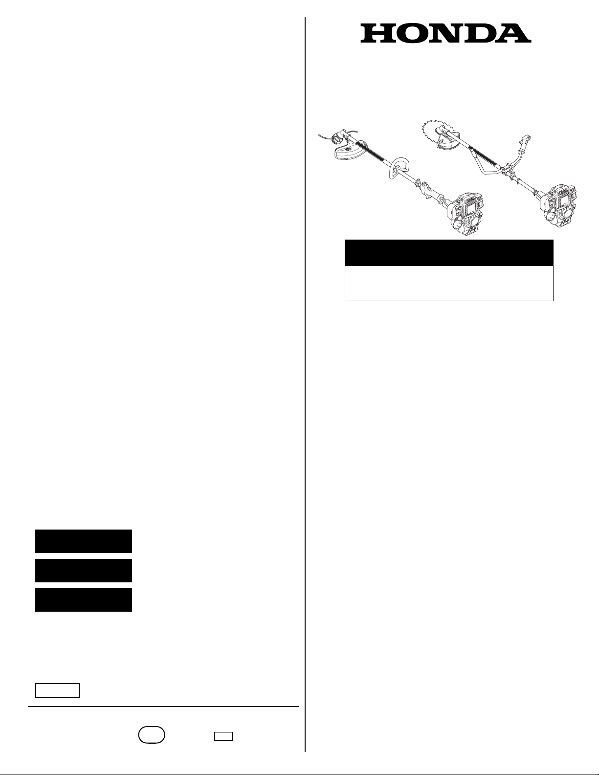
OWNER’S MANUAL
HHT25S • HHT35S
Trimmer/Brush Cutter
WARNING:
The engine exhaust from this product contains
chemicals known to the State of California to cause
cancer, birth defects or other reproductive harm.
CONTENTS
SAFETY MESSAGES
Your safety and the safety of others are very important. We have
provided important safety messages in this manual and on the
trimmer/brush cutter. This information alerts you to potential hazards
that could hurt you or others. Please read these messages carefully.
Of course, it is not practical or possible to warn you about all the
hazards associated with operating or maintaining a trimmer/brush
cutter. You must use your own good judgment.
You will find important safety information in a variety of forms:
• Safety Labels – on the trimmer/brush cutter.
• Instructions – how to use this trimmer/brush cutter correctly and
safely.
• Safety Messages – preceded by a safety alert symbol and one
of three signal words: DANGER, WARNING, or CAUTION. These
signal words mean:
DANGER
WARNING
CAUTION
Each message tells you what the hazard is, what can happen, and
what you can do to avoid or reduce injury.
• Damage Prevention Messages – You will also see other
important messages that are preceded by the word NOTICE. This
word means:
NOTICE
© 2004-2008 American Honda Motor Co., Inc.—All Rights Reserved
31VL3D11
00X31-VL3-D110
Your trimmer or other property can be
damaged if you don’t follow instructions.
You WILL be KILLED or SERIOUSLY
HURT if you don't follow instructions.
You CAN be KILLED or SERIOUSLY
HURT if you don't follow instructions.
You CAN be HURT if you don't follow
instructions.
EM5
POM31VL3D11
IPC
xxxx.2008.02
PRINTED IN U.S.A.
INTRODUCTION...............................1
SAFETY MESSAGES........................1
TRIMMER SAFETY...........................2
IMPORTANT SAFETY
INFORMATION.............................2
ATTACHMENTS &
MODIFICATIONS .........................2
IMPORTANT MESSAGE TO
EMPLOYERS ...............................2
SAFETY LABEL LOCATIONS......3
RECOMMENDED CUTTING
ATTACHMENTS................................3
CUTTING-LINE HEADS AND
SHIELDS ......................................3
BLADES AND SHIELDS...............4
ASSEMBLY .......................................5
IMPORTANCE OF PROPER
ASSEMBLY ..................................5
IMPORTANT SAFETY
PRECAUTIONS............................5
UNPACKING ................................5
LOOSE PARTS ............................6
U-TYPE HANDLEBAR..................6
SAW BLADE.................................7
ENGINE OIL.................................8
BEFORE USING YOUR
TRIMMER..................................8
CONTROLS AND EQUIPMENT........9
COMPONENT CONTROLS AND
LOCATIONS.................................9
CONTROLS..................................9
EQUIPMENT ..............................10
BEFORE OPERATION....................11
ARE YOU READY TO OPERATE
THE TRIMMER?.........................11
IS YOUR WORKING AREA
READY? .....................................11
IS YOUR TRIMMER READY TO
GO?............................................11
ARE YOUR SHOULDER HARNESS
AND TRIMMER CORRECTLY
ADJUSTED?...............................12
OPERATION ...................................12
SAFE OPERATING
PRECAUTIONS........................12
STARTING THE ENGINE...........13
STOPPING THE ENGINE.......... 13
TRIMMER/HARNESS QUICK
DISCONNECTION......................14
TRIMMER OPERATION.............14
SAFE OPERATING PRACTICES15
OPERATING TIPS .....................15
SERVICING YOUR TRIMMER........16
THE IMPORTANCE OF
MAINTENANCE..........................16
MAINTENANCE SAFETY...........16
MAINTENANCE SCHEDULE.....17
ENGINE......................................17
CUTTING ATTACHMENTS........19
FUEL SYSTEM...........................24
COOLING FIN INSPECTION .....24
STORAGE.......................................25
TRANSPORTING............................26
TAKING CARE OF UNEXPECTED
PROBLEMS.....................................26
TECHNICAL INFORMATION..........27
EMISSION CONTROL SYSTEM27
SPECIFICATIONS......................28
CONSUMER INFORMATION .........29
DISTRIBUTOR'S LIMITED
WARRANTY............................... 30
ACCESSORIES, REPLACEMENT
PARTS, AND APPAREL
WARRANTY............................... 30
EMISSION CONTROL SYSTEM
WARRANTY............................... 31
QUICK REFERENCE
INFORMATION...........................32
1
Page 2

TRIMMER SAFETY
IMPORTANT SAFETY INFORMATION
The Honda HHT25S and HHT35S trimmer/brush cutters are designed
to cut grass, weeds, brush, and/or wood if equipped with an
appropriate cutting attachment. Other uses can result in injury to the
operator or damage to the trimmer and other property.
These Honda trimmers are intended for use by gardening
professionals. Never allow children to operate the trimmer.
Most accidents can be prevented if you follow all instructions in this
manual and on the trimmer. The most common hazards are
discussed below, along with the best way to protect yourself and
others.
Keep the Trimmer Properly Maintained
• The cutting attachment should be examined for looseness, cracks,
broken parts, or excessive wear. Tighten or replace as needed
before operating the trimmer.
• Do not operate the trimmer without a debris shield properly
installed. Make sure you have the right shield installed for your
cutting attachment.
For more information, see page 4.
ATTACHMENTS & MODIFICATIONS
Modifying your trimmer/brush cutter, or installing non-Honda
attachments, can make your trimmer unsafe. Before you make any
modifications or install any attachments, be sure to read the following
information.
Always Wear Eye Protection and Protective Clothing
• The most frequent injuries associated with string trimmers are eye
injuries caused by thrown debris. Always wear safety glasses or
goggles that meet the ANSI Z87.1 rating whenever you use the
trimmer.
• The operator must wear hearing protectors when using this
trimmer. Hearing protectors will protect the operator's ears from
noise damage.
• Wearing protective clothing also reduces the risk and severity of
injury from thrown debris or contact with the cutting attachment.
Wear the trimmer harness, gloves, a long-sleeved shirt, long pants,
and sturdy boots with nonslip soles.
See page 11 for more information.
Keep Away From Cutting Lines and Blades
• A spinning cutting blade can cut through your clothes and skin just
as easily as it cuts through grass and dirt. Keep all parts of your
body away from a spinning cutting attachment.
• Even after the engine has stopped, the cutting attachment will spin
for several seconds. Do not touch it until it has stopped spinning, or
you may get cut.
Turn the Engine Off When Not Trimming
If you stop trimming or cutting for any reason, even to clean off the
cutting attachment, always shut off the engine.
Keep People Away From Your Working Area
To prevent injury to others, keep people at least 50 feet (15 meters)
away from the working area during operation.
Always Wear the Harness When Trimming
The harness keeps the trimmer away from your body, lowering your
chances of being cut by the trimmer’s blade or cutting line.
Read This Manual Before Using the Trimmer
Read the manual before operating the trimmer. Understand how to
use all the controls and obey all warnings.
Attachments
Your Honda trimmer servicing dealer has cutting attachments, debris
shields, barrier kits, and shoulder harnesses that have been designed
and approved for your trimmer and are covered by warranty.
Non-Honda attachments are usually designed for universal
applications. Although aftermarket attachments may fit on your
trimmer, they may not meet factory specifications and could make
your trimmer unsafe.
Modifications
Do not remove the debris shield or modify your trimmer in any way
that would alter its design or operation. This could make your trimmer
unsafe.
IMPORTANT MESSAGE TO EMPLOYERS
As an employer, you have special responsibilities to the people who
work for you.
Before you ask anyone to operate this trimmer/brush cutter, you need
to determine whether the operator is old enough, large enough, and
strong enough to safely handle and control the trimmer/brush cutter.
If you decide he/she is, make sure the employee(s) read and
understand all instructions and warnings in this manual and on the
labels before operating the trimmer/brush cutter.
Allow adequate time for hands-on training by a qualified instructor,
and personally supervise practice sessions, until you feel sure the
employee is ready to operate the trimmer/brush cutter.
Also be sure employees wear proper clothing, eye and hearing
protection, and any other gear that may be required by local
ordinances or your insurance company.
Remember, too, that you are responsible for keeping the
trimmer/brush cutter properly maintained and in safe operating
condition.
Your commitment to safety on the job can help prevent accidents and
result in longer and more productive years of service.
Clear the Working Area First
Objects thrown by the trimmer can cause serious injury. Before
operating the trimmer, carefully inspect the area and remove any
broken glass, pieces of wire, and other loose objects.
2
Page 3
SAFETY LABEL LOCATIONS
The labels shown here contain important safety information. Please
read them carefully. These labels are considered permanent parts of
your trimmer/brush cutter. If a label comes off or becomes hard to
read, contact an authorized Honda servicing dealer for a replacement.
TYPE EQUIPPED WITH
LOOP HANDLE
RECOMMENDED CUTTING ATTACHMENTS
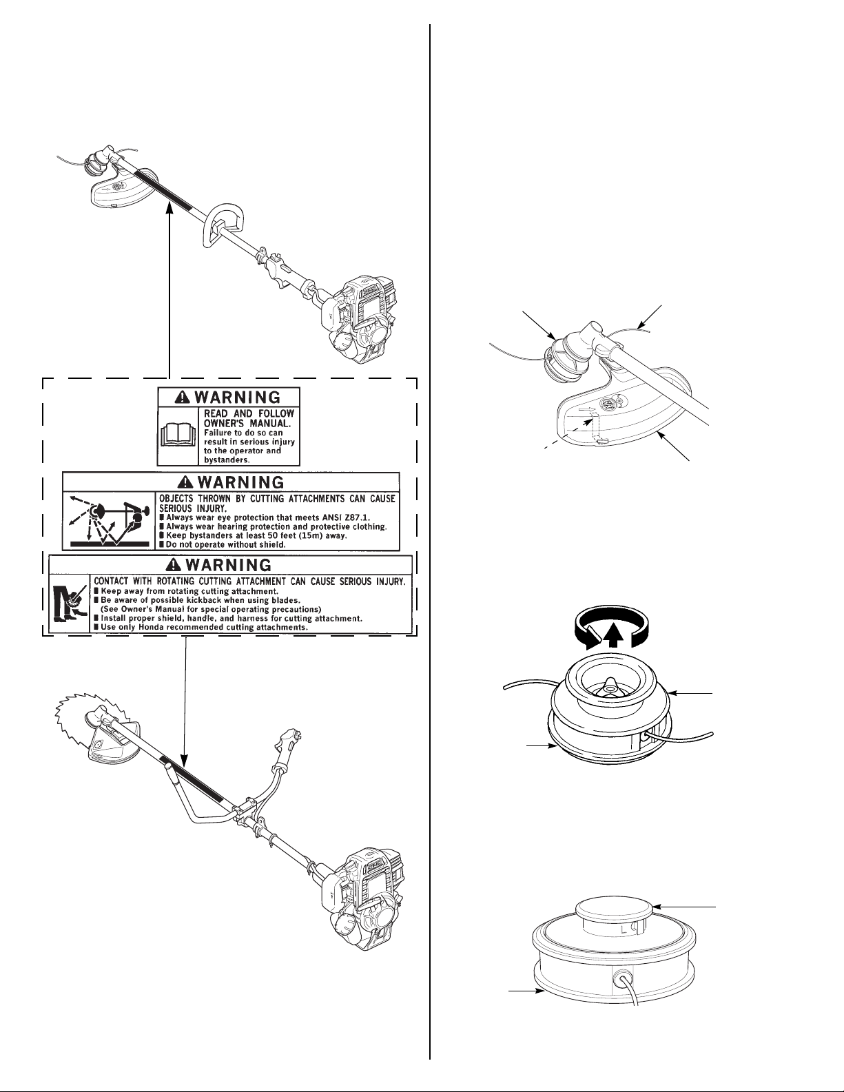
CUTTING-LINE HEADS AND SHIELDS
A cutting-line head containing nylon monofilament line and a debris
shield with a cutoff knife is standard equipment. The shield’s cutoff
knife automatically removes any excess line that is released from the
cutting head.
The U-type handlebar trimmers are supplied with two different debris
shields. Use the debris shield with the cutoff knife when the
cutting-line head is installed.
Nylon monofilament line is suitable for cutting grass and ordinary
weeds, but not brush and woody growth.
CUTTING-LINE HEAD
CUTOFF KNIFE
(inside the debris shield)
NYLON MONOFILAMENT LINE
DEBRIS SHIELD
Manual-Feed Cutting-Line Head
Line is released from the cutting head by manually pulling and turning
the spool with the trimmer engine stopped.
To release more line,
pull the spool and turn
it counterclockwise.
SPOOL
TYPE EQUIPPED WITH
U-TYPE HANDLEBAR
HOUSING
Semi-Matic (bump-feed) Cutting-Line Head
Line is released from the cutting head by bumping the spool on hard
ground while the head is spinning. Do not tap the cutting-line head on
pavement or concrete.
SPOOL
HOUSING
3
Page 4
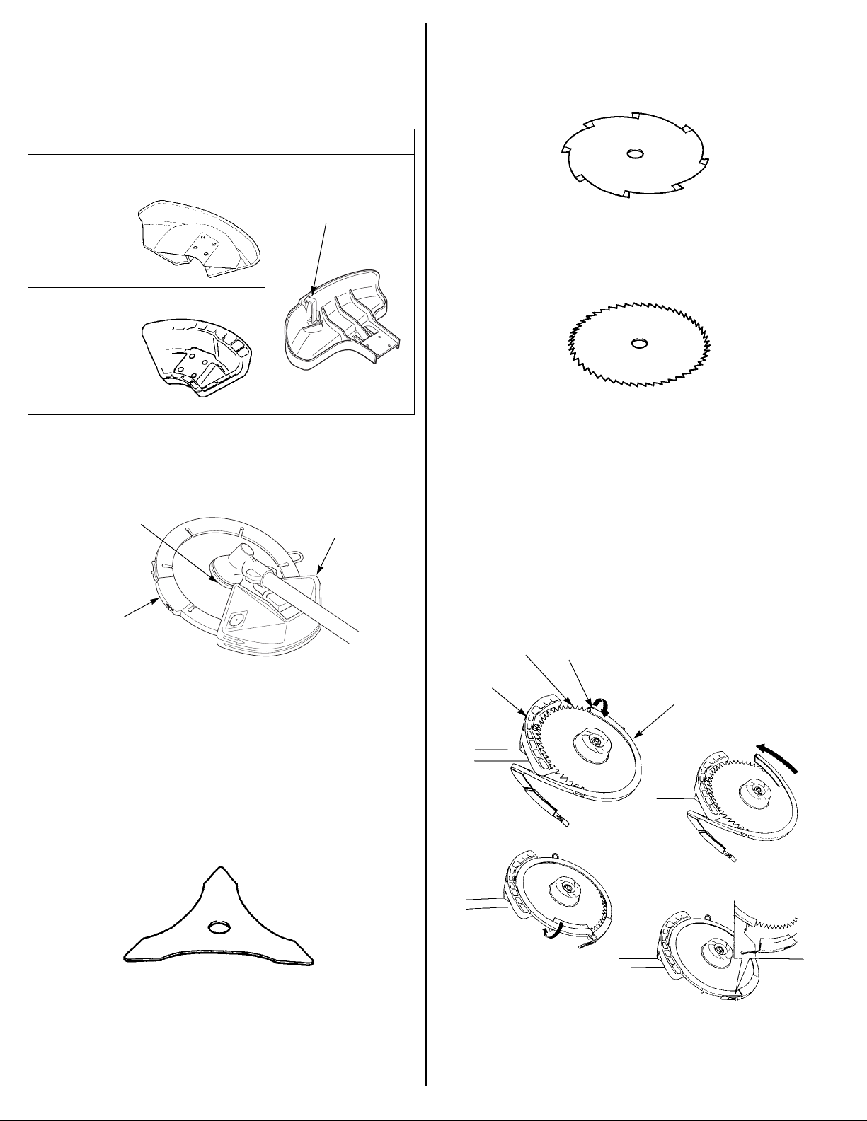
BLADES AND SHIELDS
A variety of blades are available from your Honda trimmer servicing
dealer. Always use a debris shield designed for use with a blade when
attaching a blade to your trimmer. The blade type debris shield does
not have a cutoff knife.
DEBRIS SHIELDS
BLADE CUTTING-LINE
Weed/Brush Blades
These metal blades have chisel-shaped teeth that are used for cutting
through field grass, thick weeds, and light brush. They are not
designed for sawing woody material. The teeth must be sharp for
good results.
GRASS/WEED
BLADE, WEED/
BRUSH BLADE
(optional part)
BRUSH/WOOD
BLADE
CUTOFF KNIFE
Honda U-type handlebar trimmers are supplied with a blade cover
surrounding the edge of the blade. For safety, and to protect the
blade, the cover should be installed whenever the trimmer is not in
use.
BLADE
BLADE
COVER
DEBRIS
SHIELD
If installing a metal blade on a Honda trimmer equipped with a loop
handle, also install the optional barrier kit that includes a full shoulder
harness, a barrier bar, and a debris shield for metal blades. Follow the
safety information and installation instructions that come with the kit.
Brush/Wood Blades
These metal saw-tooth blades are used for sawing through saplings,
shrubs and woody brush. The teeth must be sharp for good results.
Brush/wood blades will also cut grass and weeds, but they are not
efficient for that purpose.
Brush/Wood Blade Cover Installation and Removal
1. Install the blade cover over the blade so half the blade is covered.
To prevent the post end from interfering with the debris shield, pull
the post end away from the blade and set it on top of the blade as
shown.
Turn the blade cover slowly until the post end clears the debris
shield.
2. Reposition the post end over the blade.
3. With the blade cover fully seated on the blade, latch the tab over
the post.
Remove the blade cover in the reverse order of installation.
BLADE
DEBRIS
SHIELD
POST END
BLADE COVER
Grass/Weed Blades
Grass/weed blades, which may be plastic or metal, are used as an
alternative to nylon monofilament line for cutting grass and ordinary
weeds.
However, blades should never be used for edging against solid
surfaces.
4
Page 5
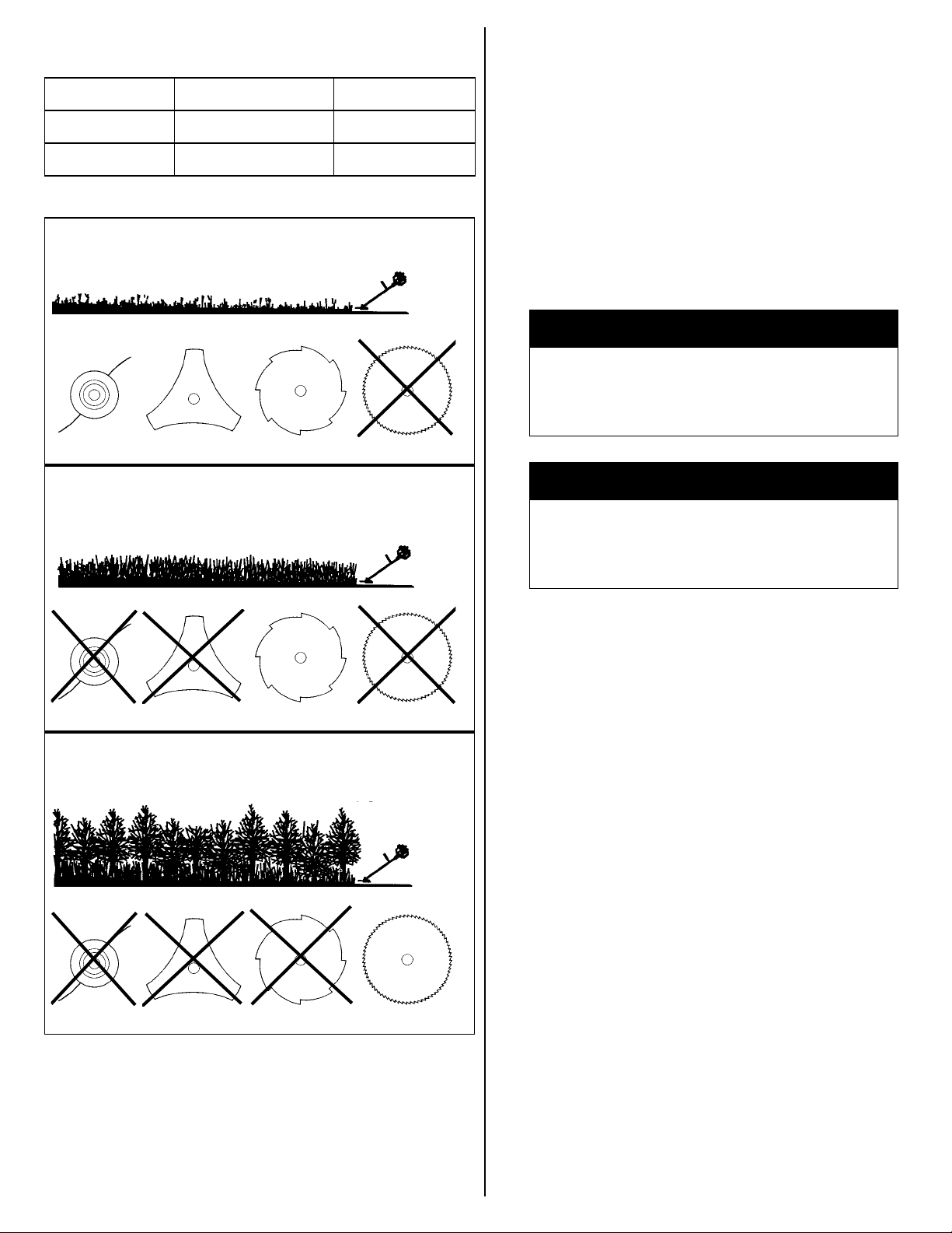
CUTTING ATTACHMENT APPLICATIONS
ASSEMBLY
Type Line Size Blade Diameter
HHT25S 0.095 in 9 in
HHT35S 0.095 or 0.105 in 9 or 10 in
ATTACHMENTS FOR TRIMMING GRASS AND LIGHT WEEDS
ATTACHMENTS FOR CUTTING THICK WEEDS AND LIGHT
BRUSH
After assembly and before operation, review the SAFE OPERATING
PRECAUTIONS on page 12.
IMPORTANCE OF PROPER ASSEMBLY
Proper assembly is essential to operator safety and the reliability of
the machine. Any error or oversight made by the person assembling
and servicing a machine can result in faulty operation, damage to the
machine, or injury to the operator.
Some of the most important safety precautions are given below.
However, we cannot warn you of every conceivable hazard that can
arise in performing this assembly. Only you can decide whether or not
you should perform a given task.
WARNING
Improper assembly can cause an unsafe condition that
can lead to serious injury or death.
Follow the procedures and precautions in the assembly
instructions carefully.
WARNING
Failure to properly follow instructions and precautions
can cause you to be seriously hurt or killed.
Follow the procedures and precautions in this manual
carefully.
ATTACHMENTS FOR CUTTING WOODY BRUSH, SHRUBS,
SAPLINGS
Your Honda trimmer servicing dealer has cutting attachments that
have been designed and approved for your trimmer and are covered
by warranty. Non-Honda attachments are usually designed for
universal applications. Although aftermarket attachments may fit on
your trimmer, they may not meet factory specifications and could
make your trimmer unsafe.
IMPORTANT SAFETY PRECAUTIONS
• Make sure you have a clear understanding of all basic shop safety
practices and that you are wearing appropriate clothing and safety
equipment.
• Read the instructions before you begin and be sure you have the
tools and skills required to perform the tasks safely.
• Make sure the engine is off before you begin any maintenance or
repairs. This will help eliminate several potential hazards:
T Carbon monoxide poisoning from engine exhaust. Be sure
there is adequate ventilation whenever you run the engine.
T Burns from hot parts. Let the engine and exhaust system
cool before touching.
T Injury from moving parts. Do not run the engine unless the
instruction tells you to do so. Even then, keep your hands,
fingers, and clothing away from moving parts. Do not run the
engine when any protective guard or shield is removed.
• To reduce the possibility of a fire or explosion, be careful when
working around gasoline or batteries. Use only a nonflammable
solvent, not gasoline, to clean parts. Keep all cigarettes, sparks,
and flames away from all fuel-related parts.
UNPACKING
Carefully remove the trimmer and loose parts from the carton and
compare the loose parts with the inventory list on page 6.
Tools Required (U-type handlebar only):
A 4 mm hex wrench, 8 and 17 mm sockets, 0 to 25 ft-lb torque
wrench.
5
Page 6
LOOSE PARTS
U-TYPE HANDLEBAR
Check all loose parts against the following list. Contact your
authorized Honda servicing dealer if any of the loose parts shown are
not included with your trimmer.
Ref.
No
Description All
Loop
handle
U-type
handlebar
Qty.
1 Owner’s Manual • 1
2 Goggles • 1
3 Oil bottle • 1
Single-strap shoulder
4
harness
• 1
5 Full shoulder harness • 1
Debris shield, for
6
30 ~ 80 tooth saw
• 1
blades only
7 Cover • 1
Left-hand thread lock
8
9
nut, 10 mm
Saw blade,
50 tooth/10 in
• 1
• 1
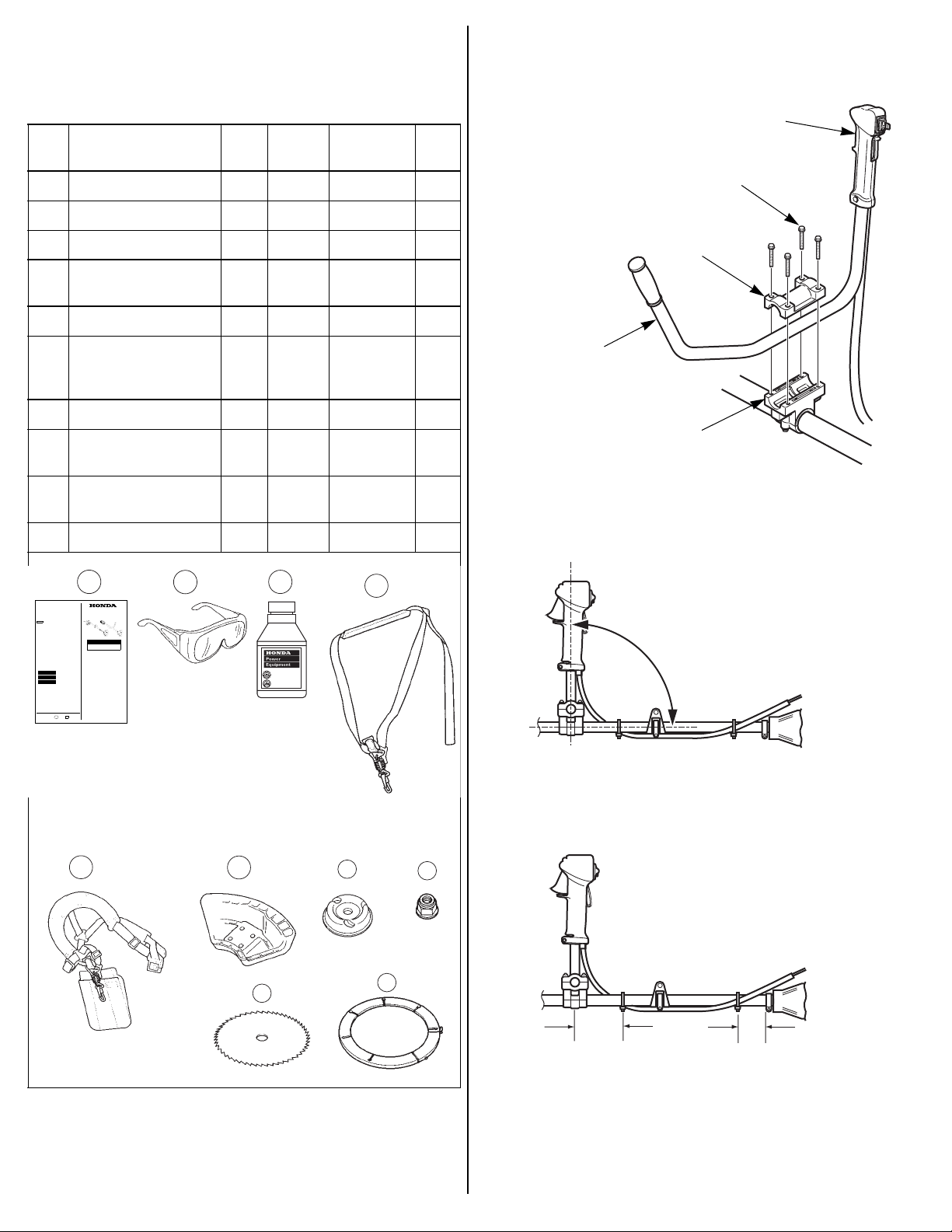
Installation
1. Remove the four 5 x 28 mm bolt/washers and handlebar holder A.
THROTTLE TRIGGER
5 x 28 mm
BOLT/WASHER (4)
HANDLEBAR
HOLDER A
U-SHAPED
HANDLEBAR
HANDLEBAR
HOLDER B
2. Set the U-shaped handle into handlebar holder B with the throttle
trigger facing to the right.
10 Blade cover • 1
INTRODUCTION
Congratulations on your selection of a Honda trimmer/brush cutter!
We are certain you will be pleased with your purchase of one of the
finest trimmer/brush cutters on the market.
We want to help you get the best results from your new trimmer/brush
cutter and to operate it safely. This manual contains the information
on how to do that; please read it carefully.
As you read this manual, you will find information preceded by a
symbol. That information is intended to help you avoid
NOTICE
damage to your trimmer/brush cutter, other property, or the
environment.
We suggest you read the Distributor’s Limited Warranty (page30) and
theEmission Control System Warranty (page31) to fully understand
its coverage and your responsibilities of ownership.
When your trimmer/brush cutter needs scheduled maintenance, keep
in mind that your Honda servicing dealer is specially trained in
servicing Honda trimmers/brush cutters. Your Honda servicing dealer
is dedicated to your satisfaction, and will be pleased to answer your
questions and concerns.
SAFETY MESSAGES
Your safety and the safety of others are very important. We have
provided important safety messages in this manual and on the
trimmer/brush cutter. This information alerts you to potential hazards
that could hurt you or others. Please read these messages carefully.
Of course, it is not practical or possible to warn you about all the
hazards associated with operating or maintaining a trimmer/brush
cutter. You must use your own good judgment.
You will find important safety information in a variety of forms:
• Safety Labels – on the trimmer/brush cutter.
• Safety Messages – preceded by a safety alert symbol and one
of three signal words: DANGER, WARNING, or CAUTION. These
signal words mean:
You WILL be KILLED or SERIOUSLY
DANGER
HURT if you don't follow instructions.
You CAN be KILLED or SERIOUSLY
WARNING
HURT if you don't follow instructions.
You CAN be HURT if you don't follow
CAUTION
instructions.
• Safety Headings—such as IMPORTANT SAFETY
INFORMATION.
• Safety Section—such as TRIMMER SAFETY.
• Instructions – how to use this trimmer/brush cutter correctly and
safely.
This entire book is filled with important safety information—please
read it carefully.
© 2004-2006 American Honda Motor Co., Inc.—All Rights Reserved
31VL3D10
IPC
EM5
00X31-VL3-D100
CONTENTS
TRIMMER SAFETY........................................................................................................2
RECOMMENDED CUTTING ATTACHMENTS..............................................................3
ASSEMBLY.....................................................................................................................5
CONTROLS AND EQUIPMENT.....................................................................................9
BEFORE OPERATION.................................................................................................11
OPERATION.................................................................................................................12
SERVICING YOUR TRIMMER.....................................................................................16
STORAGE.....................................................................................................................25
TRANSPORTING..........................................................................................................26
TAKING CARE OF UNEXPECTED PROBLEMS.........................................................26
TECHNICAL INFORMATION........................................................................................27
CONSUMER INFORMATION.......................................................................................29
POM53509-C
XXXX.2006.12
PRINTED IN U.S.A.
1
OWNER’S MANUAL
HHT25S • HHT35S
Trimmer/Brush Cutter
WARNING:
The engine exhaust from this product contains
chemicals known to the State of California to cause
cancer, birth defects or other reproductive harm.
IMPORTANT SAFETY INFORMATION..................................................................2
ATTACHMENTS & MODIFICATIONS.....................................................................2
IMPORTANT MESSAGE TO EMPLOYERS...........................................................2
SAFETY LABEL LOCATIONS.................................................................................3
CUTTING-LINE HEADS AND SHIELDS.................................................................3
BLADES AND SHIELDS..........................................................................................4
CUTTING ATTACHMENT APPLICATIONS............................................................5
IMPORTANT SAFETY PRECAUTIONS..................................................................5
UNPACKING...........................................................................................................5
LOOSE PARTS.......................................................................................................6
U-TYPE HANDLEBAR.............................................................................................6
SAW BLADE............................................................................................................7
ENGINE OIL............................................................................................................8
SAFE OPERATING PRECAUTIONS....................................................................12
STOPPING THE ENGINE.....................................................................................13
TRIMMER/HARNESS QUICK DISCONNECTION................................................14
TRIMMER OPERATION........................................................................................14
SAFE OPERATING PRACTICES..........................................................................15
OPERATING TIPS.................................................................................................15
MAINTENANCE SAFETY......................................................................................16
MAINTENANCE SCHEDULE................................................................................17
ENGINE.................................................................................................................17
CUTTING ATTACHMENTS...................................................................................18
FUEL SYSTEM......................................................................................................24
EMISSION CONTROL SYSTEM...........................................................................27
SPECIFICATIONS.................................................................................................28
DISTRIBUTOR'S LIMITED WARRANTY..............................................................30
ACCESSORIES, REPLACEMENT PARTS, AND APPAREL WARRANTY..........30
EMISSION CONTROL SYSTEM WARRANTY.....................................................31
2
1
3
10W-30
Genuine Honda Oil
Specially formulated and
blended for Honda engines.
Meets or exceeds American
Petroleum Institute SJ
standards.
100 cc / 3.4 oz
4
U-Type Handlebar Only
5
6
9
7
8
10
3. Adjust the handlebar position as shown.
90°
4. Tighten the four 5 x 28 mm bolt/washers.
TORQUE: 3.6 ft-lb (5 N·m)
5. Make sure the tie straps are positioned as shown.
3.9 in (100 mm) 2.4 in (60 mm)
6. Operate the throttle trigger and make sure the throttle operates
smoothly.
6
Page 7
SAW BLADE
The U-type handlebar models are shipped with a manual nylon
cutting-line head installed on the trimmer. If the saw blade is needed,
move the ignition switch to the STOP (O) position and disconnect the
spark plug cap from the spark plug. Wear protective gloves when
working around the cutting-line head and saw blade.
2. Install the brush/wood blade debris shield.
Tighten the bolt/washers:
TORQUE: 2.5 ft-lb (3.4 N·m)
5 x 28 mm
BOLT/WASHER (4)
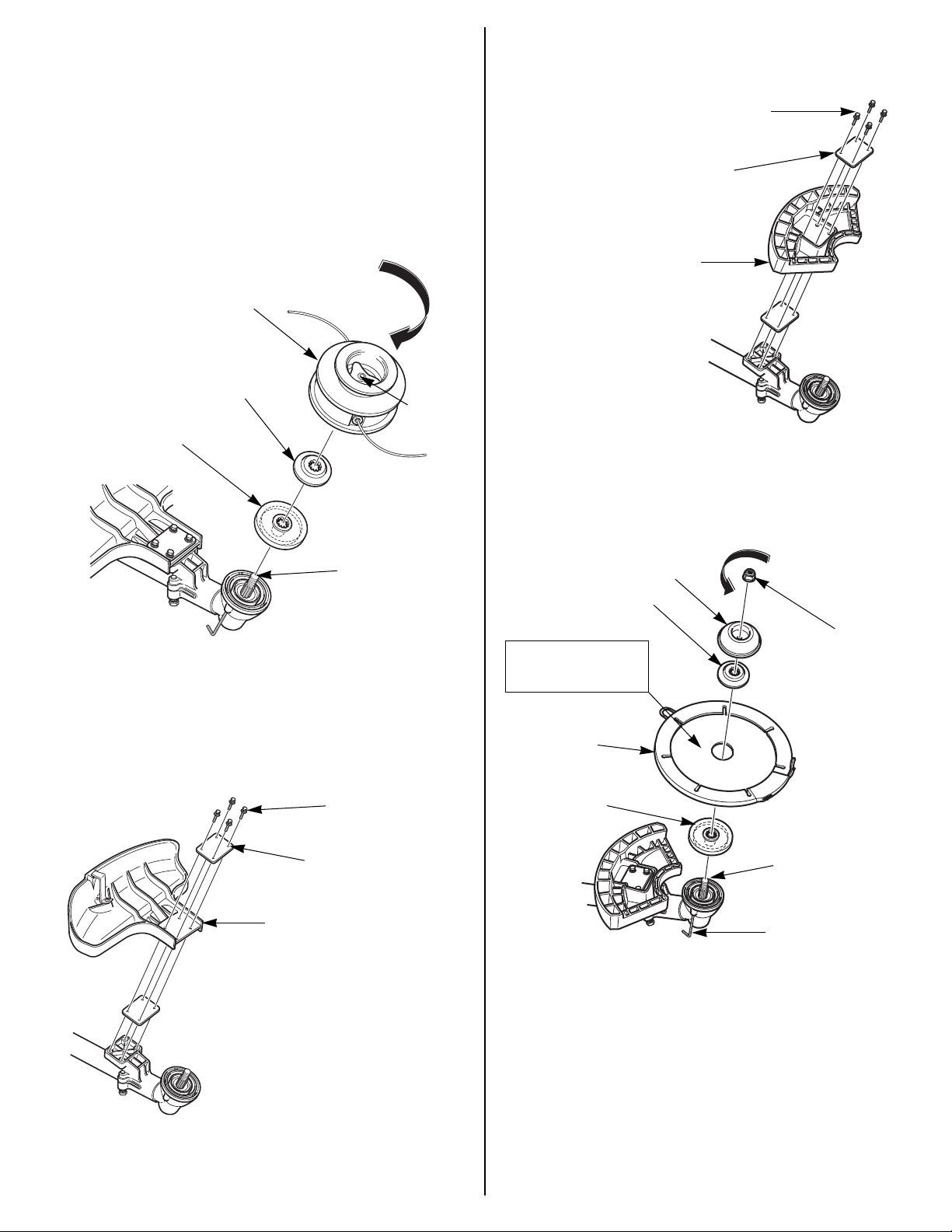
Cutting-Line Head Removal
1. Align the gear case hole with the groove in cover plate/spacer A.
Insert a 4 mm hex wrench or equivalent into the gear case hole to
prevent the left-hand threaded output shaft from turning.
CUTTING-LINE HEAD
ASSEMBLY
SPACER B
COVER PLATE/
SPACER A
OUTPUT SHAFT
(left-hand thread)
2. Hold the wrench and rotate the cutting-line head in the direction of
the arrow and remove the cutting-line head assembly.
KNOB
(Do Not
Remove)
[3/32" (2.3 mm) thick]
BRUSH/WOOD BLADE
DEBRIS SHIELD
SPACER (2)
Saw Blade Installation
1. Insert a 4 mm hex wrench or equivalent into the gear case hole to
prevent the output shaft from turning.
2. Install cover plate/spacer A onto the output shaft as shown.
TIGHTEN
COVER
SPACER B
BLADE
Install with the white
markings facing the
debris shield.
10 mm LOCK NUT
(left-hand thread)
Remove the cutting-line head as an assembly. Do not remove the
knob. Refer to page 20 for a cutting-line head assembly drawing.
Debris Shield Removal/Installation
1. Remove the cutting-line debris shield.
5 x 28 mm
BOLT/WASHER (4)
SPACER (2)
[3/32" (2.3 mm) thick]
CUTTING-LINE
DEBRIS SHIELD
(with cutoff knife)
BLADE
COVER
COVER PLATE/
SPACER A
OUTPUT SHAFT
(left-hand thread)
4 mm HEX TOOL
3. With the blade cover installed on the blade, install the blade by
aligning the center of the blade with the shoulder on cover plate/
spacer A.
4. Install spacer B, the cover, and the 10 mm lock nut as shown.
Be sure to install the blade with the cutting edges of the saw teeth
in the direction of rotation; the side with the white markings must
face the debris shield.
The output shaft has left-hand threads. Tighten the 10 mm lock nut
counterclockwise.
TORQUE: 14 ft-lb (20 N•m)
5. Remove the 4 mm hex wrench or equivalent from the gear case.
7
Page 8
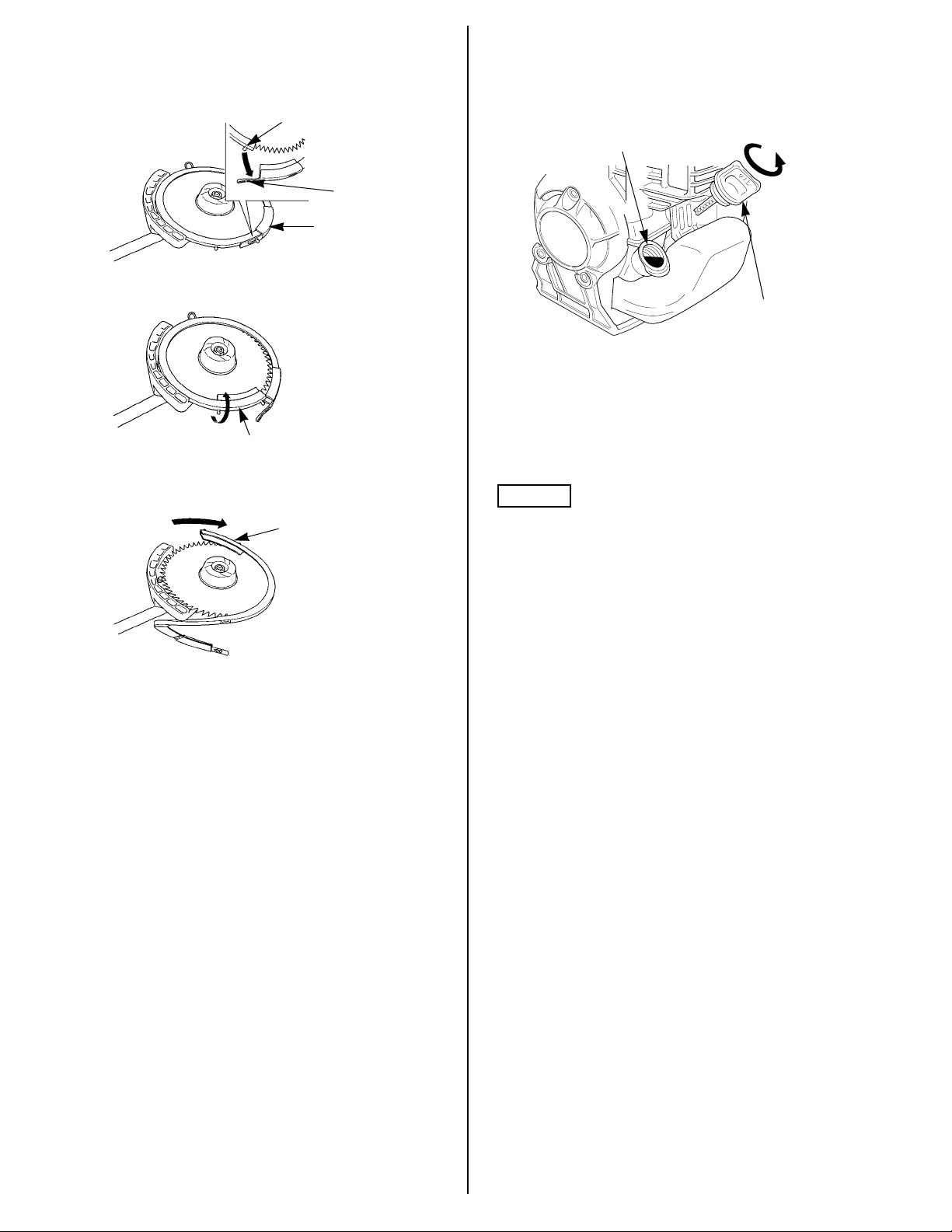
Blade Cover Removal
1. Turn the blade cover slowly until the cover latch is clear of the
debris shield.
Unfasten the latch by lifting the tab off the post.
POST
TAB
BLADE COVER
2. Pull the post end away from the blade and set it on top of the blade
as shown.
POST END
3. Turn the blade cover slowly until the post end is clear of the debris
shield, then remove the blade cover from the blade.
POST END
ENGINE OIL
The trimmer is shipped WITHOUT OIL in the engine.
1. Place the trimmer on a level surface then remove the oil filler
cap/dipstick.
OIL FILLER OPENING
OIL FILLER CAP/DIPSTICK
2. Slowly add the recommended oil (included in the box) to the
bottom edge of the oil filler opening. Do not overfill, as the engine
oil tank capacity is small.
3. If the supplied oil is not used, add enough SAE 10W-30 API
service category SJ or later oil. Add oil until the oil level is to the
bottom edge of the oil filler opening.
NOTICE
Running the engine with too little or too much oil can cause engine
damage.
4. Screw in the oil filler cap/dipstick securely.
Blade Cover Installation
1. Install the blade cover over the blade so half of the blade is
covered.
To prevent the post end from interfering with the debris shield, pull
the post end away from the blade and set it on top of the blade as
shown above.
2. Turn the blade cover slowly until the post end clears the debris
shield.
3. Reposition the post end over the blade.
4. With the blade cover fully seated on the blade, latch the tab over
the post.
FUEL
See page 24.
BEFORE USING YOUR TRIMMER
On blade equipped models, always remove the blade cover before
starting the engine. If the cover is not removed, the blade cover may
fly off at high speed during test operation. Reinstall the blade cover
when the trimmer is not being used.
Before using the trimmer, all trimmer operators must read the
following sections.
• TRIMMER SAFETY (page 2)
• CONTROLS & EQUIPMENT (page 9)
• BEFORE OPERATION (page 11)
• OPERATION (page 12)
• MAINTENANCE SCHEDULE (page 17)
8
Page 9
CONTROLS AND EQUIPMENT
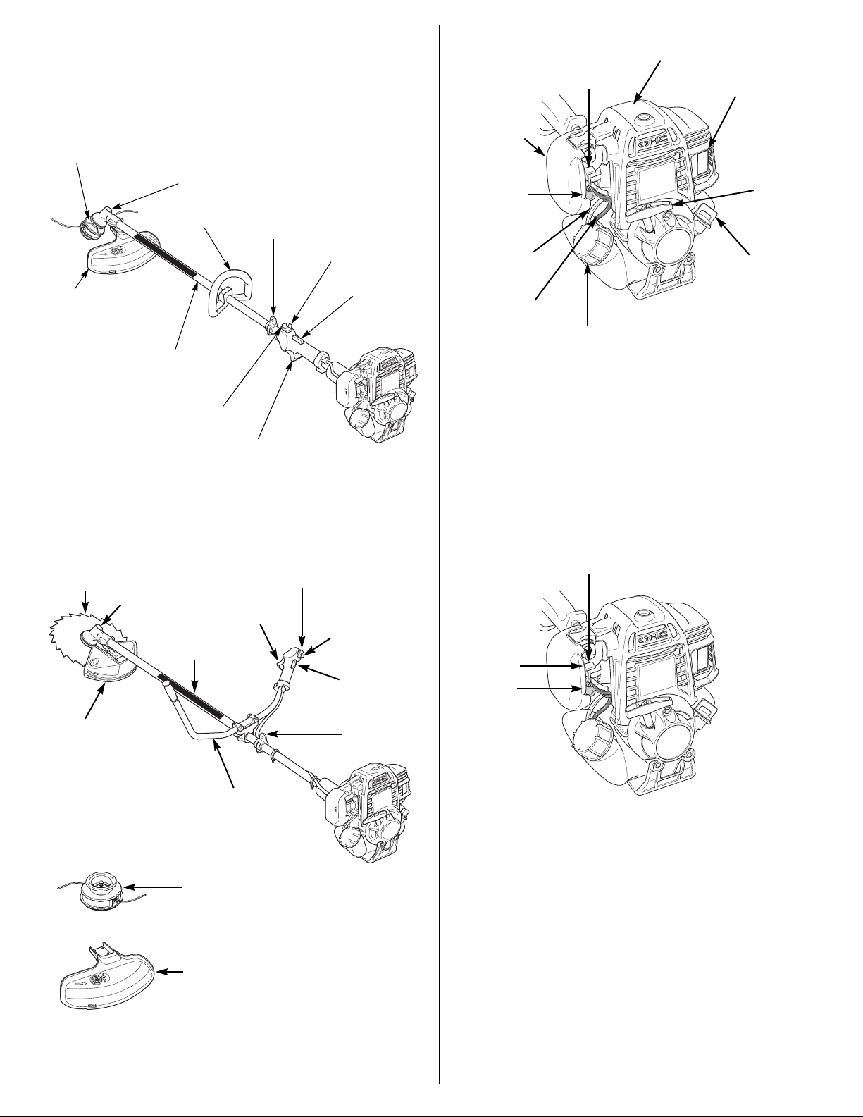
COMPONENT CONTROLS AND LOCATIONS
Loop Type Handle
CUTTING-LINE HEAD
GEAR CASE
LOOP HANDLE
DEBRIS SHIELD
WITH CUTOFF KNIFE
DRIVE CABLE
FRAME PIPE
IGNITION SWITCH
HARNESS HANGER
THROTTLE SET BUTTON
OPERATOR
PRESENCE
LEVER
Engine
CHOKE LEVER
AIR
CLEANER
COVER
PRIMING
BULB
FUEL RETURN
TUBE (CLEAR)
FUEL SUPPLY
TUBE (BLACK)
FUEL TANK CAP
SPARK PLUG
SPARK
ARRESTER
STARTER
GRIP
OIL FILLER CAP
CONTROLS
The location and operation of the controls are similar on both the
HHT25S and HHT35S models.
THROTTLE
TRIGGER
U-Type Handlebar
This type is supplied with a cutting-line head, a saw blade, and two
debris shields.
SAW BLADE
GEAR CASE
DEBRIS SHIELD
FOR BRUSH/
WOOD BLADE
THROTTLE
TRIGGER
DRIVE CABLE
FRAME PIPE
U-TYPE
HANDLEBAR
IGNITION SWITCH
THROTTLE
SET BUTTON
OPERATOR
PRESENCE
LEVER
HARNESS
HANGER
Choke Lever
The choke lever opens and closes the choke valve.
The CLOSED position enriches the fuel mixture for starting a cold
engine.
The OPEN position provides the correct fuel mixture for operation
after starting, and for restarting a warm engine.
CHOKE LEVER
CLOSED
OPEN
CUTTING-LINE HEAD
DEBRIS SHIELD WITH
CUTTING KNIFE
9
Page 10
Ignition Switch
The ignition switch controls the ignition system.
The ignition switch must be in the ON (I) position for the engine to
start and run.
Moving the ignition switch to the STOP (O) position stops the engine.
Priming Bulb
Pressing the priming bulb pumps fuel from the fuel tank to the
carburetor. This procedure is necessary for starting the engine.
To ensure fuel has reached the carburetor, press the priming bulb
repeatedly until fuel can be seen in the clear plastic fuel return tube.
U-type Handle:
STOP
(O)
ON (I)
IGNITION
SWITCH
OPERATOR PRESENCE LEVER
STOP (O)
IGNITION
SWITCH
Loop Handle:
ON (I)
OPERATOR
PRESENCE
LEVER
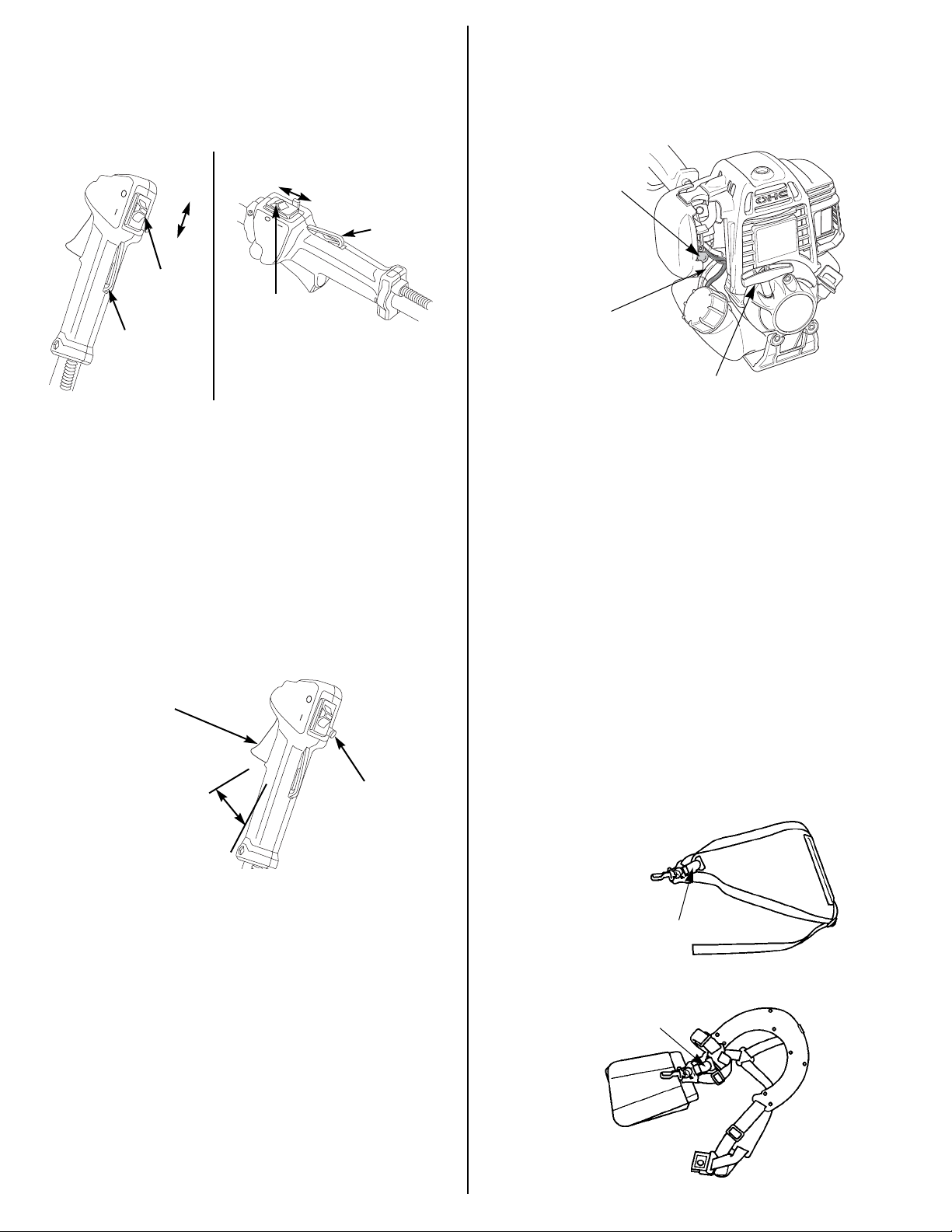
Operator Presence Lever
The operator presence lever blocks the throttle trigger. This safety
feature prevents unintentional throttle operation if the trimmer is
bumped while the operator’s hand is not on the control handle.
When the operator presses the presence lever by gripping the control
handle, the trigger moves freely.
Throttle Trigger
The throttle trigger controls engine speed.
Pulling the throttle trigger toward the control handle grip increases
engine speed. The trimmer will have the greatest cutting force at
maximum engine speed.
Releasing the throttle trigger reduces engine speed. At idle, the
cutting attachment should coast to a stop.
THROTTLE TRIGGER
(cutting attachment stops)
IDLE
THROTTLE SET BUTTON
PRIMING
BULB
FUEL RETURN TUBE
(clear plastic tube)
RECOIL STARTER GRIP
Recoil Starter Grip
Pulling the starter grip operates the recoil starter to turn the engine for
starting.
EQUIPMENT
The Honda HHT25S and HHT35S trimmer/brush cutters are supplied
with a shoulder harness and safety glasses. Refer to page 11 for a
description of other equipment and protective clothing you will need.
Shoulder Harness
A full shoulder harness must be worn by the operator of these Honda
trimmers/brush cutters when equipped with a blade and debris shield.
If the trimmer is equipped with a cutting-line head and shield with
cutoff knife, the operator may wear a single-strap harness.
A suitable shoulder harness is supplied with each new Honda
HHT25S and HHT35S trimmer/brush cutter. Replacement shoulder
harnesses may be purchased through any authorized Honda
trimmer/brush cutter servicing dealer.
Before operation, adjust your shoulder harness as described on
page 12.
SINGLE-STRAP SHOULDER HARNESS (Loop type handle)
(cutting attachment rotates)
FAST
Throttle Set Button
The throttle set button is used to hold the throttle trigger at the fast idle
position for starting. Do not allow the cutting line or blade to contact
any obstruction when starting the engine with the throttle set button
engaged.
To engage the throttle set button, press the operator presence lever
by gripping the control handle, pull the throttle trigger, then press and
hold the throttle set button while releasing the throttle trigger.
To disengage the throttle set button, simply pull the throttle trigger.
The throttle set button automatically disengages when the throttle
trigger is pulled.
Do not use the throttle set button while operating the trimmer. The
trimmer will not return to idle, and the cutting-line head or blade will
continue to spin until the throttle set button is disengaged and the
throttle trigger is released.
10
QUICK-RELEASE LATCH
FULL SHOULDER HARNESS (U-type handlebar)
QUICK-RELEASE LATCH
Page 11

Quick-Release Latch
The shoulder harnesses supplied with these trimmers are equipped
with a quick-release latch.
Pull the latch tab upward to detach the trimmer from the harness.
Insert the latch tongue in the slot of the quick-release latch to reattach
the trimmer to the harness.
LATCH TAB
Eye, Face, and Head Protection
Always wear safety glasses or goggles that comply with ANSI
standard Z87.1 to protect your eyes from thrown objects. Prescription
glasses may be worn under the safety glasses or goggles.
A helmet with a face shield is recommended for further protection.
However, safety glasses or goggles should always be worn under the
face shield. Do not rely on a face shield alone to protect your eyes.
Wearing a dust mask will help to reduce the amount of pollen and dust
inhaled.
Hearing Protection
Hearing protectors will help to protect your ears from noise.
Earmuff-style hearing protectors can also protect your ears from
thrown objects.
Hand and Body Protection
Wear gloves, a long-sleeved shirt, and long pants made of heavy
material. Clothing should fit closely but allow freedom of movement,
and should have no strings, straps, etc. that could catch on brush or
the trimmer. Keep clothing fastened.
QUICK-RELEASE LATCH
Safety Glasses
Safety glasses or goggles that comply with ANSI (American National
Standards Institute) standard Z87.1 must be worn by the operator of
any Honda trimmer/brush cutter. The safety glasses supplied with
each new Honda HHT25S and HHT35S trimmer/brush cutter comply
with this ANSI standard.
SAFETY GLASSES (ANSI Z87.1)
BEFORE OPERATION
ARE YOU READY TO OPERATE THE TRIMMER?
Your safety is your responsibility. A little time spent in preparation will
significantly reduce your risk of injury.
Knowledge
Read and understand this manual. Know what the controls do and
how to operate them.
Familiarize yourself with the trimmer and its operation before you
begin to use it. Know what to do in case of emergencies.
Physical and Mental Readiness
You must be alert and in good physical condition to operate the
trimmer. Do not operate the trimmer if you are tired, ill, or under the
influence of alcohol, medication, or any substance that might impair
your vision, dexterity, or judgment.
If you have any physical problem that may be aggravated by
strenuous work, consult your physician before operating the trimmer.
Foot Protection
Wear sturdy work boots with good toe protection and nonslip soles.
IS YOUR WORKING AREA READY?
Objects thrown by the trimmer can cause serious injury. Before
operating the trimmer, carefully inspect the area and remove all
objects that could be thrown by, or entangled in, the cutting
attachment, such as rocks, broken glass, nails, wire, or string.
Clear the area of children, bystanders, and pets. Keep all children,
bystanders, and pets at least 50 feet (15 meters) away from where the
trimmer is being operated.
Even outside a 50-foot (15-meter) radius of the trimmer, there may be
a risk of injury from thrown objects, so bystanders should be
encouraged to wear eye protection.
If anyone approaches you while you are operating the trimmer,
release the throttle trigger and stop the engine.
IS YOUR TRIMMER READY TO GO?
For your safety, and to maximize the service life of your equipment, it
is very important to take a few moments before you operate the
trimmer to check its condition. Be sure to take care of any problem
you find, or have your servicing dealer correct it, before you operate
the trimmer.
WARNING
Improperly maintaining this trimmer, or
failing to correct a problem before operation,
could cause a malfunction in which you
could be seriously injured.
Always perform a pre-operation inspection
before each operation, and correct any
problem.
Protective Clothing
Wearing protective clothing will reduce your risk of injury. Do not wear
loose clothing, jewelry, short pants, sandals, or go barefoot. Secure
hair so it is above shoulder level.
Safety Inspection
• Look around the engine for signs of oil or gasoline leaks. Wipe up
any spills before starting the engine.
• Replace any damaged parts.
• Check that all fasteners are in place and secure. Tighten as
necessary.
11
Page 12

Cutting Attachment Inspection
• Look for signs of damage to the cutting attachment (see page 19
and page 22). Replace any cutting attachment and parts that are
worn out, bent, cracked, chipped, or damaged in any way.
• If using a metal blade, be sure it is sharp. A dull blade is more likely
to snag and thrust.
• If using a metal blade on a trimmer equipped with a loop handle, be
sure the barrier bar (optional part) is installed beneath the loop
handle.
• Make sure the cutting attachment is properly installed and securely
fastened (see page 22 and page 23).
• Check that the debris shield is the correct shield for the cutting
attachment (see page 23), and that it is securely installed and in
good condition.
Maintenance Inspection
• Check the oil level (see page 17). Running the engine with a low oil
level can cause engine damage.
• Check the air filter (see page 18). A dirty air filter will restrict air flow
to the carburetor, reducing engine and trimmer performance.
• Check throttle cable free play (see page 18). The cable must be
correctly adjusted and operate smoothly for good throttle control.
• Check the fuel level (see page 24). Starting with a full tank will help
to eliminate or reduce operating interruptions for refueling.
ARE YOUR SHOULDER HARNESS AND TRIMMER CORRECTLY ADJUSTED?
Adjusting the Harness
Adjust the harness so the quick-release latch is at your right hip, as
shown.
QUICK-RELEASE
LATCH
Balancing the Trimmer on the Shoulder Harness
Hang the trimmer on the harness hook, and see how it balances.
Adjust the shoulder harness, the harness hanger on the frame pipe,
and the loop handle or U-type handlebar, so the handle or handlebars
are in a comfortable operating position, and the trimmer hangs with its
cutting attachment a few inches above the ground (see page 14).
A few inches above the
ground
GROUND
OPERATION
SAFE OPERATING PRECAUTIONS
Before operating the trimmer for the first time, please review the
IMPORTANT SAFETY INFORMATION section on page 2 and
BEFORE OPERATION section starting on page 8.
Even if you have operated other trimmers, take time to become
familiar with the operation of this trimmer’s controls and handling.
For your safety, avoid starting or operating the engine in an enclosed
area, such as a garage. Your engine's exhaust contains poisonous
carbon monoxide gas which can collect rapidly in an enclosed area
and cause illness or death.
If the trimmer starts to shake or vibrate, stop the engine immediately.
After the cutting head has completely stopped, inspect it to determine
the cause of the vibration. Sudden vibration is a sign of a hazardous
problem, such as a loose or damaged blade. Do not operate the
trimmer until the problem is corrected.
Prolonged exposure to vibration may cause vibration syndrome
(Raynaud's disease). Symptoms include loss of skin color in the
hands and numbness or a painful tingling sensation in the fingers,
hands, and arms. Regular users of any power equipment may feel the
numbness or pain spontaneously, at any time, not just after using the
equipment. If any of these symptoms occur, see a physician
immediately.
FULL SHOULDER
HARNESS
12
SINGLE-STRAP
SHOULDER HARNESS
Page 13

STARTING THE ENGINE
1. To start a cold engine, move the choke lever to the CLOSED
position.
To restart a warm engine, leave the choke lever in the OPEN
position.
CHOKE LEVER
CLOSED
OPEN
6. With your left hand, hold the frame pipe just ahead of the engine.
With your right hand, pull the starter grip lightly until you feel
resistance, then pull briskly. Return the starter grip gently.
7. If the choke lever was moved to the CLOSED position to start the
engine, gradually move it to the OPEN position as the engine
warms up.
Allow the engine to warm up for a few minutes after a cold start.
When the engine is warm enough to idle well, pull and release the
throttle trigger to disengage the throttle set button.
8. With the engine idling, hook the trimmer to your shoulder harness.
Be careful to avoid contact with the cutting-line head or blade while
handling the trimmer with the engine running.
PRIMING
BULB
FUEL RETURN
TUBE
(clear plastic
tube)
2. To start a cold engine, or after refueling an engine that has run out
of fuel, press the priming bulb repeatedly until fuel can be seen in
the clear plastic fuel return tube.
To restart a warm engine, it is not necessary to press the priming
bulb.
3. Set the throttle trigger in the starting position, using the throttle set
button.
To set the throttle trigger for starting, press the operator presence
lever by gripping the control handle, pull the throttle trigger, then
press and hold the throttle set button while releasing the throttle
trigger.
IGNITION SWITCH
ON (I)
THROTTLE
TRIGGER
THROTTLE
SET BUTTON
OPERATOR
PRESENCE
LEVER
4. Move the ignition switch to the ON (I) position.
5. Set the trimmer on the ground, resting on the debris shield and the
fuel tank guard. Do not allow the cutting-line or blade to contact
any obstruction.
Always rest the trimmer on the ground for starting, rather than
holding it in the operating position. This prevents the end of the
trimmer from swinging into something as you start the engine.
QUICK-RELEASE
LATCH
HOOK
The cutting-line head or blade should not rotate with the engine
idling. If there is rotation at idle, adjust the idle speed correctly
before using the trimmer. For idle adjustment, consult your
authorized Honda servicing dealer.
STOPPING THE ENGINE
THROTTLE
TRIGGER
1. Release the throttle trigger.
2. Move the ignition switch to the STOP (O) position.
Wait for the cutting line head or blade to stop before allowing the
end of the trimmer to contact anything.
STOP (O)
IGNITION
SWITCH
WARNING
The blade will continue to spin briefly after
the engine has stopped or the throttle trigger
is released.
A coasting blade can cause injury.
Maintain proper control of the trimmer until
the blade has completely stopped rotating.
13
Page 14

TRIMMER/HARNESS QUICK DISCONNECTION
To quickly detach the trimmer from the harness, pull the quick-release
latch tab upward.
LATCH TAB
QUICK-RELEASE
LATCH
Throttle Operation
Pull the throttle trigger toward the grip to increase engine speed and
start the cutting attachment rotation.
The trimmer has the greatest cutting force at maximum engine speed.
Release the throttle trigger to reduce engine speed. At idle, the cutting
attachment should coast to a stop.
THROTTLE
TRIGGER
Insert the latch tongue in the slot of the quick-release latch to reattach
the trimmer to the harness.
TRIMMER OPERATION
Operating Position
Hold the trimmer firmly with both hands, with your fingers and thumbs
encircling the handles as shown. This will help you to keep the
trimmer under control at all times.
• Keep firm footing and balance.
• Do not overreach.
• Keep the cutting attachment below waist level.
• Keep all parts of your body away from the rotating cutting
attachment and hot surfaces.
(cutting attachment stops)
IDLE
FAST
(cutting attachment rotates)
Using a Nylon Cutting-Line Head
As the ends of the line wear away, more line must be released from
the cutting-line head. Your trimmer is factory-equipped with either a
manual-feed or a semi-matic (bump feed) cutting-line head, which
have different procedures for releasing line.
The debris shield is equipped with a cutoff knife that automatically
removes any excess line that is released.
Manual-Feed Cutting-Line Head
Line must be released with the cutting-line head stopped.
1. Stop the engine, and wait for the cutting-line head to coast to a
complete stop.
2. Hold the housing, pull the spool out about a quarter of an inch, then
turn the spool counterclockwise until it snaps into the housing
again.
The spool will snap into the housing every sixth of a turn, which
releases 1 to 1-1/2 inches of line.
To release more line,
pull spool and turn
counterclockwise.
14
HOUSING
SPOOL
Semi-Matic (bump-feed) Cutting-Line Head
Line must be released with the cutting-line head spinning rapidly.
With the engine running at full speed, tap the cutting-line head on
hard, bare ground. Do not tap the cutting-line head on pavement or
concrete.
Each tap releases about 2 inches of line.
SPOOL
HOUSING
Page 15

Using Blades
Refer to the chart on page 5 for appropriate blade applications.
If using a blade on a Honda trimmer equipped with a loop handle, also
install the optional Honda conversion kit that includes a full shoulder
harness, a barrier bar, and a debris shield for blades. Follow the
installation instructions and safety information that come with the kit.
Metal blades supplied with U-type handlebar models are supplied with
a cover surrounding the edge of the blade. For your safety, and to
protect the blade, the cover should be installed whenever the trimmer
is not in use.
Be sure to remove the blade cover before starting the engine.
Otherwise, the blade cover may fly off at high speed.
If the trimmer starts to vibrate after the blade strikes an object, stop
the engine immediately and check the blade for damage. A damaged
blade may break, and pieces of broken blade can become dangerous
projectiles. Replace the blade if it is broken, cracked, bent, or
damaged in any way.
SAFE OPERATING PRACTICES
Be very careful when operating the trimmer over uneven or rough
ground, and when the ground is wet and slippery. Watch out for
hidden obstacles that could cause you to stumble. Operate the
trimmer only under conditions with good visibility. Do not operate the
trimmer where you cannot see what it is cutting.
WARNING
Rotating cutting lines can cause serious abrasions and cuts,
and blades can cut deeply.
• Keep away from the cutting lines or blade whenever the
engine is running.
• Always stop the engine, and be sure the cutting line head
or blade has stopped turning, before inspecting or
handling the cutting lines or blade.
Thrown Debris
The trimmer will throw debris in the direction of blade movement at
the point of contact.
The cutting line head or blade rotates counterclockwise, as viewed
from the operator’s position. Tilting the cutting line head to the right
will throw debris away from you, and tilting to the left will throw debris
toward you.
DEBRIS
Blade Thrust (Kickback)
Blade thrust (kickback) is the sudden, forceful, and uncontrolled
movement of a blade-equipped trimmer that may occur if the blade
binds while cutting or strikes a solid object.
Blade thrust (kickback) throws the trimmer in the direction opposite
blade rotation at the point of contact, and the jolt received by the
operator can result in further loss of control.
BLADE
THRUST
To reduce the risk of loosing control, use metal blades on trimmers
equipped with a U-type handlebar, or install the barrier bar (optional
part) on trimmers equipped with a loop handle.
Replace or resharpen dull blades. Dull blades are more likely to bind
in the cut and cause blade thrust.
Watch out for hidden obstacles such as rocks, stumps, roots, etc., that
could cause the blade to kick back if struck. Blade thrust is more likely
to occur in areas where it is difficult to see what is being cut.
Understand the reaction forces of the blade. When using a brush
blade to saw through heavy brush and small saplings, saw with the
side of the brush blade that is moving toward you and tends to pull the
trimmer away from you.
Blades on Honda HHT25S and HHT35S trimmers rotate
counterclockwise, as viewed from the operator’s position. Therefore,
the left side of the blade is moving toward you. With these trimmers,
sawing with the left side of a brush blade will give you better control
and less risk of kickback, though it will throw the sawdust toward you.
Cut from the side of saplings that will cause them to fall away from the
trimmer. This will help prevent the blade from binding in the cut and
kicking back.
Accelerate the engine to maximum speed before starting the cut, and
saw through with uniform pressure.
OPERATING TIPS
Cut with the right
side to throw debris
away from you.
If the cutting line head or blade is held parallel to the ground, debris
will scatter in all directions and there will be greater friction, which will
wear out the cutting line or blade sooner.
When operating the trimmer near a hard surface such as a wall, work
from an angle where debris that strikes the hard surface will ricochet
away from you.
Gravel, loose stones, etc. can be picked up by the nylon cutting lines
or blade and thrown many feet with enough force to cause serious
personal injury and/or property damage. Before crossing graveled
areas, release the throttle trigger to stop the cutting line head or
blade.
Scything
Swing the trimmer in a level arc by rotating your body with a smooth,
easy motion, rather then moving the trimmer with your arms. Do not
chop at tough weeds and brush; let the cutting line or blade work
through tough growths gradually.
To direct thrown debris away from you, tilt the cutting attachment to
the right side, scythe from left to right, then return without cutting.
15
Page 16

Trimming and Edging
Use nylon line for cutting against a hard surface. Work from an angle
where debris that strikes the hard surface will ricochet away from you.
Avoid contact with wires, wire fences, metal rods, etc. Overlapping a
wire will cause the nylon line to wrap around the wire and break off.
SERVICING YOUR TRIMMER
THE IMPORTANCE OF MAINTENANCE
Good maintenance is essential for safe, economical, and trouble-free
operation. It will also help reduce air pollution.
DEBRIS
TRIMMING
Brush Clearing
Clearing brush with a brush blade may require both scything and
sawing.
Scything with the right side of the blade will direct thrown debris away
from you.
Be especially careful to direct debris away from you if recutting an
area to shorten stumps. Short lengths of shrub and sapling stumps
may tear off and be thrown at high speed.
Sawing heavy brush and saplings with the left side of the blade will
reduce the risk of kickback.
Accelerate the engine to maximum speed before starting the cut, and
saw through with uniform pressure.
If shrubs or saplings bind the blade, stop the engine, and while
supporting the weight of the trimmer, push the shrub or sapling away
to free the blade. Do not use the blade as a lever.
WARNING
Improperly maintaining this trimmer, or failure to correct a
problem before operation, can cause a malfunction in
which you can be seriously hurt or killed.
Always follow the inspection and maintenance
recommendations and schedules in this owner's manual.
To help you properly care for your trimmer, the following pages
include a maintenance schedule, routine inspection procedures, and
simple maintenance procedures using basic hand tools. Other service
tasks that are more difficult, or require special tools, are best handled
by professionals and are normally performed by a Honda technician
or other qualified mechanic.
The maintenance schedule applies to normal operating conditions. If
you operate your trimmer under severe conditions, such as sustained
high-load or high-temperature operation, or use it in unusually wet or
dusty conditions, consult your authorized Honda servicing dealer for
recommendations applicable to your individual needs and use.
Remember that your authorized Honda servicing dealer knows your
trimmer best and is fully equipped to maintain and repair it.
To ensure the best quality and reliability, use only new, Honda
Genuine parts or their equivalents for repair and replacement.
Maintenance, replacement, or repair of the emission control
devices and systems may be performed by any engine repair
establishment or individual, using parts that are “certified” to
EPA standards.
MAINTENANCE SAFETY
Some of the most important safety precautions follow. However, we
cannot warn you of every conceivable hazard that can arise in
performing maintenance. Only you can decide whether or not you
should perform a given task.
SAWING
Operation on Slopes
Start on the low side of a slope, and work upward. This will reduce
your risk of slipping and falling, and it will give you a cutting angle that
will better enable you to direct debris away from you.
Do not let the cutting line or blade dig into the slope, because that can
cause stones and dirt to be thrown at you.
Do not raise the cutting attachment above waist level during
operation, because that would increase the risk of thrown objects
striking your face.
Avoid steep slopes that would require holding the cutting attachment
above waist level. Avoid slippery slopes that might cause you to lose
your balance.
16
WARNING
Failure to properly follow maintenance instructions and
precautions can cause you to be seriously hurt or killed.
Always follow the procedures and precautions in the
owner's manual.
Safety Precautions
• Make sure the engine is off before you begin any maintenance or
repairs. This will eliminate several potential hazards:
— Carbon monoxide poisoning from engine exhaust.
Be sure there is adequate ventilation whenever you operate the
engine.
— Burns from hot parts.
Let the engine and exhaust system cool before touching.
— Injury from moving parts.
Do not run the engine unless instructed to do so.
• Read the instructions before you begin, and make sure you have
the tools and skills required.
Page 17

• To reduce the possibility of fire or explosion, be careful when
working around gasoline. Use only a nonflammable solvent, not
gasoline, to clean parts. Keep cigarettes, sparks, and flames away
from all fuel-related parts.
MAINTENANCE SCHEDULE
ENGINE
Engine Oil Level Check
Check the engine oil level before each use, or every 10 hours if
operated continuously. Rest the trimmer on a level surface, with the
engine stopped and in an upright position.
Interval
1
Item
Before each use Check the engine oil (page 17)
Check the air cleaner (page 18)
Check the throttle cable (page 18)
Check the cutting attachment
Check the debris shield
Check/tighten nuts, bolts, and fasteners
Check the shoulder harness quick release
First month or
Change the engine oil (page 17)
10 hours
Every 3 months or
Clean the air filter element (page 18)
25 hours
Every 6 months or
50 hours
Change the engine oil (page 17)
Clean the air filter element (page 18)
Check/lubricate the drive cable
Lubricate the gear case
3
Check the clutch shoes and drum
Check the engine cooling fins
Every year or 100
hours
Perform the 50-hour service items plus:
Check/adjust the idle speed
3
Check/adjust the valve clearance
Check/adjust the spark plug
Check the spark arrester
Check the fuel filter
Clean the fuel tank
OIL FILLER
CAP/DIPSTICK
FILLER OPENING
1. Remove the filler cap/dipstick and wipe it clean.
2
2. Insert and remove the dipstick without screwing it into the filler
opening. Check the oil level shown on the dipstick.
2
2
3
3
3. If the oil level is low, fill to the edge of the oil filler hole with the
recommended oil (see page 18). To avoid overfilling or underfilling,
be sure the engine is in a level position, as shown.
NOTICE
Running the engine with too little or too much oil can cause engine
damage.
4. Screw in the oil filler cap/dipstick securely.
3
Engine Oil Change
Drain the used oil while the engine is warm. Warm oil drains quickly
and completely.
Every 2 years or
300 hours
Every 2 years Check the fuel tubes and replace if necessary
Perform the 100-hour service items plus:
Replace the spark plug (page 18)
Clean the combustion chamber
3
Check the oil tube and replace if necessary
3
3
1. Log the hours of operation to determine the proper maintenance
interval.
2. Service more frequently when used in dusty areas.
3. These items should be serviced by an authorized Honda servicing
dealer unless you have the proper tools and are mechanically
proficient. Refer to the Honda shop manual for service procedures.
Failure to follow this maintenance schedule could result in
non-warrantable failures.
FILLER
OPENING
1. Place a suitable container below the engine to catch the used oil,
then remove the filler cap/dipstick and drain the used oil through
the filler opening. Allow the used oil to drain completely.
Please dispose of used motor oil in a manner that is compatible
with the environment. We suggest you take used oil in a sealed
container to your local recycling center or service station for
reclamation. Do not throw it in the trash or pour it on the ground or
down a drain.
2. With the engine in an upright position, fill to the edge of the oil filler
hole with the recommended oil.
3. Screw in the filler cap/dipstick securely.
17
Page 18

Engine Oil Recommendations
Oil is a major factor affecting performance and service life. Use
4-stroke automotive detergent oil.
SAE 10W-30 is recommended for all temperatures within the
recommended operating range for these trimmers. The recommended
operating range extends from 23° ~ 104°F (-5° ~ 40°C).
The SAE oil viscosity and service classification are on the API label
on the oil container. Honda recommends that you use API SERVICE
category SJ or later.
Air Filter Check
Squeeze the air cleaner latch tabs, and remove the air cleaner cover.
Check the filter to be sure it is clean and in good condition.
If the filter is dirty, clean it as described under Air Filter Cleaning.
Replace the filter if it is damaged. Reinstall the filter and air cleaner
cover.
NOTICE
Operating the engine without an air filter, or with a damaged air filter,
will allow dirt to enter the engine, causing rapid engine wear. This type
of damage is not covered by the DISTRIBUTOR'S LIMITED
WARRANTY.
Throttle Cable Inspection
Verify the throttle trigger operates smoothly and the throttle cable is
undamaged. If there is visible damage, or if the throttle trigger does
not operate smoothly, have your authorized Honda servicing dealer
replace the throttle cable.
Check the free play at the end of the throttle cable.
Free play: 1/16 ~ 1/8 in (1.0 ~ 3.0 mm)
If adjustment is needed, use the following cable adjustment
procedure.
CABLE END
FREE PLAY
1/16 ~ 1/8 in
(1.0 ~ 3.0 mm)
Air Filter Cleaning
A dirty air filter will restrict air flow to the carburetor, reducing engine
performance. If you operate the engine in very dusty areas, clean the
air filter more often than specified in the MAINTENANCE
SCHEDULE.
1. Clean the air filter in warm soapy water, rinse, and allow to dry
thoroughly. Or clean in nonflammable solvent and allow to dry.
2. Dip the air filter in clean engine oil, then squeeze out all excess oil.
The engine will smoke when started if too much oil is left in the
filter.
3. Wipe dirt from the air cleaner base and cover using a moist rag. Be
careful to prevent dirt from entering the carburetor.
FILTER
AIR CLEANER
COVER
LOCK NUT
ADJUSTING
NUT
Throttle Cable Adjustment
1. Loosen the lock nut with a 10 mm wrench, and turn the adjusting
nut as required.
• Turn the adjusting nut left for more free play.
• Turn the adjusting nut right for less free play.
2. Tighten the lock nut and recheck cable free play.
Spark Plug Service
Recommended spark plug: CMR5HSB (NGK)
NOTICE
Incorrect spark plugs can cause engine damage.
1. Remove the 5 x 12 mm hex bolt and top cover.
5/32 in (4 mm)
HEX WRENCH
(commercially available)
5 x 12 mm
HEX BOLT
18
LATCH
TAB
RETAINING TABS
SPARK PLUG
SPARK PLUG
CAP
TOP
COVER
2. Disconnect the spark plug cap, and remove any dirt from around
the spark plug area.
3. Remove the spark plug with a 5/8-inch spark plug wrench.
Page 19

4. Inspect the spark plug. Replace it if the electrodes are worn, or if
the insulator is cracked or chipped.
2. Remove the two 4 x 6 mm self-tapping screws from the spark
arrester, and remove the spark arrester from the muffler.
5. Measure the spark plug electrode gap with a suitable gauge. The
gap should be
0.024 ~ 0.028 in (0.60 ~ 0.70 mm). Correct the gap, if necessary,
by carefully bending the side electrode.
SIDE ELECTRODE
SEALING
WASHER
GAP
0.024 ~ 0.028 in
(0.60 ~ 0.70 mm)
6. Install the spark plug carefully, by hand, to avoid cross-threading.
7. After the spark plug seats, tighten with a
5/8-inch spark plug wrench to compress
the washer.
If reinstalling the used spark plug, tighten
1/8 ~ 1/4 turn after the spark plug seats.
If installing a new spark plug, tighten 1/2 turn after the spark plug
seats.
SPARK
ARRESTER
4 x 6 mm
SELF-TAPPING
SCREWS
MUFFLER
3. Use a brush to remove carbon deposits from the spark arrester
screen. Be careful to avoid damaging the screen.
The spark arrester must be free of breaks and holes. Replace the
spark arrester if it is damaged.
SPARK ARRESTER SCREEN
NOTICE
A loose spark plug can overheat and damage the engine.
Overtightening the spark plug can damage the threads in the
cylinder head.
8. Attach the spark plug cap.
9. Install the top cover and 5 x 12 mm hex bolt and tighten securely.
Spark Arrester Service
The spark arrester must be serviced every 100 hours to keep it
functioning as designed.
If the engine has been running, the muffler will be very hot. Allow the
muffler to cool before servicing the spark arrester.
1. Remove the 5 x 12 mm hex bolt and top cover.
5/32 in (4 mm) HEX WRENCH
(commercially available)
5 x 12 mm
HEX BOLT
TOP COVER
MUFFLER
4. Install the spark arrester, top cover, and 5 x 12 mm hex bolt and
tighten securely.
CUTTING ATTACHMENTS
There are several cutting attachments for your trimmer. Use the
following section to inspect, remove, service and install a standard
(factory-installed) cutting attachment.
Always move the engine switch to the STOP (O) position and
disconnect the spark plug cap before performing any inspection,
adjustment, or maintenance on the trimmer.
Cutting-Line Heads
All Honda trimmers come with either a manual or semi-matic cutting
head. Read this section to learn how to inspect, install new line, and
remove and install a cutting head from the trimmer.
Inspection
Make sure the nylon line is only sticking out of the metal eyelets on
the head. If any of the line has come off the spool, follow the Installing
Replacement Nylon Line instructions in this section to disassemble
the spool and replace the line.
Examine the entire head area, including the debris shield, and clear or
clean it free from dirt, debris, loose string, wire, or any other foreign
materials.
For the manual feed head, make sure the three-sided knob is
correctly tightened (page 21). For the semi-matic head, verify the
spool is locked in place (page 22). For both head styles, check for any
cracks in the plastic and replace any damaged parts.
19
Page 20

Installing Replacement Nylon Line
First, determine which cutting-line head style is on your trimmer. A
manual-feed trimmer head has a three-sided knob on the bottom of
the head, while the semi-matic head has a spring-loaded round button
on the bottom of the head.
Do not use any kind of metal, wire, or wire rope line on the trimmer.
Use only Honda Genuine replacement nylon trimmer line or
equivalent.
Honda trimmers come standard with low noise line. Using non-Honda
line may result in increased noise levels.
For original, factory-installed Honda cutting-line heads, use only nylon
monofilament line in the line sizes shown below.
HHT25S 0.095 in
HHT35S 0.095 or 0.105 in
See page 30 for replacement parts information.
Manual Cutting-Line Head
1. Clean any mud, dirt, debris, etc. from the area around the trimmer
head; otherwise, it will be more difficult to service.
2. Rotate the left-hand threaded knob in the direction of the arrow and
remove the knob.
Remove the spring and spool from the housing then remove any
remaining old line from the spool.
4. Wind both lines tightly and evenly from side-to-side ignoring the
ridge. Feed the line while turning the spool in the direction of the
arrow. Do not allow the lines to get twisted.
It is important to prevent the two lines from getting twisted over
each other. Position a finger between the lines as you turn the
spool to prevent the lines from twisting.
5. When you have about 6 inches (150 mm) of line remaining, press
the lines into the two notches on the bottom of the spool. This will
hold the lines on the spool for reassembly.
HOUSING
SHAFT
SPOOL
SPRING
KNOB
(left-hand thread)
3. Measure approximately 20 feet (6 meters) of line, then thread one
end through the hole in the ridge on the spool. Pull the line until the
two line lengths are equal.
NYLON
LINE
NOTCHES
6. Feed both line ends through the metal eyelets in the housing.
Be careful not to let the line slip under the spool. When the spool
reaches the bottom of the housing, the lines should snap out of the
spool notches.
If you are not sure the lines have snapped out of the notches,
gently pull the spool away from the housing about an 1/8 inch to
inspect the lines. If necessary , gently pull each line until you hear it
snap out of the notch. Trim the lines so they are equal length.
METAL
EYELET (2)
20
SPOOL
Page 21

7. Install the spring and knob. Rotate the knob in the direction of the
arrow and hand tighten securely.
6. Measure approximately 20 feet (6 meters) of new line, then thread
one end through the hole in the ridge on the spool.
Pull the line until the two lengths are equal.
SPOOL
NYLON LINE
Semi-Matic (Bump-Feed) Cutting-Line Head
1. Clean any mud, dirt, debris, etc., from around the trimmer head
area; otherwise, it will be more difficult to service.
2. Locate the half-round locking hole on the spool.
SPOOL
HALF-ROUND
LOCKING HOLE
3. It may be necessary to lightly rotate the spool in the direction of the
arrow about an 1/8 turn until the spool stops.
7. Wind both lines tightly and evenly from side to side ignoring the
ridge. Feed the line while turning the spool in the direction of the
arrow. Do not allow the line to get twisted.
It is important to prevent the two lines from getting twisting over
each other. Position a finger between the lines as you turn the
spool to prevent the lines from twisting.
8. When you have about 6 inches (150 mm) of line remaining, press
the lines into the two notches on the bottom of the spool. This will
hold the lines on the spool for reassembly.
4. Hold the housing securely, then continue to rotate the spool in the
direction of the arrow an additional 1/4 inch or the width of the
channel to unlock the spool from the housing.
CHANNEL
HOUSING
5. Lift the spool out of the housing and remove any remaining line
from the spool.
NOTCHES
9. It may be necessary to push down and rotate the outer drive until
the round lugs align with the metal eyelets.
Feed both line ends through the metal eyelets in the housing.
Align the channels in the spool with the round lugs on the outer
drive. With the channels and notches aligned with the metal
eyelets, slide the spool into the housing with a continuous snap-in
motion. Be careful not to let the line slip under the spool. When the
spool reaches the bottom of the housing, the lines should snap out
of the spool notches.
21
Page 22

If you are not sure if the lines have snapped out of the notches,
gently pull the spool away from the housing about an 1/8 inch to
inspect the lines. If necessary , gently pull each line until your hear it
snap out of the notch.
OUTER
DRIVE
CHANNEL (2)
ROUND LUG (2)
METAL
EYELET (2)
4. Remove spacer B and cover plate/spacer A from the output shaft.
Note the order and orientation of each part as you remove them.
CUTTING-LINE HEAD
SPACER B
COVER PLATE/
SPACER A
10.Hold the housing and rotate the spool in the direction of the arrow
to lock the round lug into the half-round locking hole. Trim the lines
so they are equal length.
HALF-ROUND
LOCKING HOLE
Removal and Installation
This section shows you how to remove and install either style trimmer
head from your trimmer.
1. Insert the tip of a 4 mm hex wrench, or equivalent, fully into the
gear case hole.
2. Turn the trimmer cutting-line head until you feel the tool drop into
the hole in the cover plate/spacer A. Verify the trimmer head does
not turn.
3. All output shafts use left-hand threads. Make sure the tool remains
in the hole, then grasp the trimmer head and turn in the direction of
the arrow to remove.
REMOVAL
DIRECTION
OUTPUT SHAFT
(left-hand thread)
5. Installation is the reverse of removal. Always clean debris, dirt,
loose line, etc. from the trimmer head and output shaft area before
installation. Tighten the trimmer head securely.
Blade
Blade Inspection
Always wear gloves when working around the blade. Before each
use, check the blade for wear and damage, and check the tightness of
the blade lock nut. Examine the entire head area, including the debris
shield, and clear or clean it free from dirt, debris, loose string, wire, or
any other foreign materials.
WARNING
A worn, damaged or cracked blade can break, and pieces
of the damaged blade can become dangerous projectiles.
A dull blade is more likely to snag and thrust (kickback).
Inspect the blade regularly , and do not operate the trimmer
with a dull, worn, or damaged blade.
22
GEAR CASE
4 mm HEX WRENCH
(commercially available)
TRIMMER
HEAD
NORMAL WORN
BENT CRACKED
A dull blade can be sharpened, but a blade that is worn out, bent,
cracked, chipped, or otherwise damaged must be replaced.
When a blade needs sharping or replacement, take the trimmer to a
Honda trimmer servicing dealer. Or, if you have a torque wrench, you
can remove and install a blade yourself.
Page 23

Blade Removal and Installation
For loop handle models, a special optional Barrier Kit must be
installed before a blade can be used. Refer to the instructions
provided with each kit on how to install a blade on loop handle
models.
Always wear gloves and install the blade cover on the blade when
working around the blade.
A torque wrench is required to install the blade. If you do not have a
torque wrench, have a Honda trimmer servicing dealer tighten the
blade lock nut for you before using the trimmer.
If the blade lock nut is tightened too much, the output shaft can break.
If the blade lock nut is not tightened enough, the blade could come off.
In either case, it would be possible for the blade to fly off while you are
operating the trimmer.
The blade lock nut is specially designed for this application. When
replacing the lock nut, use only a Honda Genuine replacement lock
nut.
BLADE SHARPENING: To avoid weakening the blade or causing
imbalance or poor cutting, the blade should be sharpened by trained
staff at a Honda trimmer servicing dealer.
BLADE REPLACEMENT: Your Honda trimmer servicing dealer has
cutting attachments that have been designed and approved for your
trimmer and are covered by a warranty. Non-Honda attachments are
usually designed for universal applications. Although aftermarket
attachments may fit on your trimmer, they may not meet factory
specifications and could make your trimmer unsafe.
1. Install the protective plastic cover that came with the blade.
2. Insert a commercially available 4 mm hex tool or equivalent fully
into the gear case hole.
Changing the Debris Shield
Refer to the applicable illustration for removing and installing the
debris shields. Tighten the spacer bolts/washers to the specified
torque.
TORQUE: 2.5 ft-lb (3.4 N·m)
5 x 28 mm
BOLT/WASHER (4)
SPACER (2)
[3/32" (2.30 mm)
thick]
CUTTING-LINE
DEBRIS SHIELD
(with cutoff knife)
5 x 28 mm
BOLT/WASHER (4)
TIGHTEN
COVER
SPACER B
COVER PLATE/
SPACER A
BLADE
COVER
OUTPUT SHAFT
(left-hand thread)
4 mm HEX
TOOL
LOOSEN
10 mm LOCK NUT
(left-hand thread)
BLADE
3. Turn the blade until you feel the tool drop into the hole in cover
plate/spacer A. Verify the blade does not turn. The output shaft and
blade lock nut have a left-hand thread. Make sure the tool remains
in the hole, then loosen the blade nut as shown. Pay attention to
the order and orientation of the parts as they are removed.
SPACER (2)
[3/32" (2.3 mm) thick]
BLADE DEBRIS
SHIELD
4. Installation is the reverse of removal. Make sure you install the
blade with the cutting edges in the direction of rotation. Be sure to
align the hole in the blade with the shoulder on cover plate/spacer
A. Tighten the blade nut to the specified torque.
TORQUE: 14 ft-lb (20 N·m)
23
Page 24

FUEL SYSTEM
Refueling
This engine is certified to operate on unleaded gasoline with a pump
octane rating of 86 or higher.
You may use regular unleaded gasoline containing no more than 10%
ethanol (E10) or 5% methanol by volume. In addition, methanol must
contain cosolvents and corrosion inhibitors. Use of fuels with content
of ethanol or methanol greater than shown above may cause starting
and/or performance problems. It may also damage metal, rubber, and
plastic parts of the fuel system. Engine damage or performance
problems that result from using a fuel with percentages of ethanol or
methanol greater than shown above are not covered by warranty.
If your equipment will be used on an infrequent or intermittent basis,
please refer to the fuel section of the STORAGE chapter (page 25) for
additional information regarding fuel deterioration.
WARNING
Gasoline is highly flammable and explosive.
Fuel Filter and Fuel Tank Cleaning
1. Remove the fuel tank cap and empty the fuel tank into an approved
gasoline container. Use a funnel to avoid spilling gasoline.
2. Pull the fuel filter out through the fuel filler neck by hooking the
black fuel supply tube with a piece of wire, such as a partly
straightened paper clip.
You can be burned or seriously injured when handling fuel.
• Stop the engine and keep heat, sparks, and flame away.
• Handle fuel only outdoors.
• Wipe up spills immediately.
Check the fuel level by looking through the translucent fuel tank. If the
fuel level is low, refuel in a well-ventilated area with the engine
stopped. If the engine has been running, allow it to cool first.
Never use stale or contaminated gasoline or an oil/gasoline mixture.
Avoid getting dirt or water in the fuel tank.
To refuel, rest the trimmer on the ground with the fuel tank cap facing
up, as shown. Remove the fuel tank cap and fill the tank with gasoline
to the bottom of the filler neck. Refuel carefully to avoid spilling fuel.
Do not overfill. There should be no fuel in the filler neck. After
refueling, tighten the fuel tank cap securely.
FUEL
TANK CAP
FUEL
TANK
MAXIMUM
FUEL
LEVEL
FUEL SUPPL Y
TUBE (black)
FUEL
FILTER
3. Inspect the fuel filter. If the fuel filter is dirty, remove it and wash it
with nonflammable solvent. Be careful to avoid damaging the filter.
4. Replace the filter if it is damaged or excessively dirty.
5. Rinse sediment from the fuel tank with nonflammable solvent.
6. Insert the fuel filter in the fuel tank and install the fuel tank cap.
COOLING FIN INSPECTION
1. Remove the 5 x 12 mm hex bolt and top cover. Inspect the engine
cooling fins and clean out any dirt and debris.
ENGINE COOLING FINS
Never refuel the engine inside a building where gasoline fumes may
reach flames or sparks. Keep gasoline away from appliance pilot
lights, barbecues, electric appliances, power tools, etc.
Spilled fuel is not only a fire hazard, it causes environmental damage.
Wipe up spills immediately.
Move at least 10 feet (3 meters) away from the fueling source and site
before starting the engine.
NOTICE
Fuel can damage paint and plastic. Be careful not to spill fuel when
filling your fuel tank. Damage caused by spilled fuel is not covered
under warranty.
24
2. Install the top cover and 5 x 12 mm hex bolt, and then tighten
securely.
Page 25

STORAGE
STORAGE PREPARATION
Proper storage preparation is essential to keep your trimmer trouble
free and looking good. The following steps will help to keep rust and
corrosion from impairing your trimmer's function and appearance, and
will make the engine easier to start when you use the trimmer again.
Cleaning
Wash the trimmer, including the area around the trimmer head.
Wash the engine by hand and be careful to prevent water from
entering the air cleaner.
NOTICE
Using a garden hose or pressure washing equipment can force water
into the air cleaner. Water in the air cleaner will soak the filter and can
enter the carburetor or engine, causing damage.
Water on a hot engine can cause damage. If the engine has been
running, allow it to cool for at least 1/2 hour before washing.
If using a garden hose or pressure washing equipment to clean the
trimmer, be careful to avoid getting water into controls and cable, or
anywhere near the engine air cleaner or muffler opening.
Before washing the trimmer head area, disconnect the spark plug cap
from the spark plug.
After washing the trimmer, wipe dry all accessible surfaces.
Start the engine outdoors and let it run until it reaches normal
operating temperature to evaporate any water remaining on the
engine.
Stop the engine and allow it to cool.
After the trimmer is clean and dry, coat areas that may rust with a light
film of oil. Lubricate the control cable cores with a silicone spray
lubricant.
Fuel
NOTICE
Depending on the region where you operate your equipment, fuel
formulations may deteriorate and oxidize rapidly. Fuel deterioration
and oxidation can occur in as little as 30 days and may cause damage
to the carburetor and/or fuel system. Please check with your servicing
dealer for local storage recommendations.
Gasoline will oxidize and deteriorate in storage. Old gasoline will
cause hard starting, and it leaves gum deposits that clog the fuel
system. If the gasoline in your trimmer deteriorates during storage,
you may need to have the carburetor and other fuel system
components serviced or replaced.
The length of time that gasoline can be left in your fuel tank and
carburetor without causing functional problems will vary with such
factors as gasoline blend, your storage temperatures, and whether
the fuel tank is partially or completely filled. The air in a partially filled
fuel tank promotes fuel deterioration. Very warm storage
temperatures accelerate fuel deterioration. Fuel deterioration
problems may occur within a few months, or even less if the gasoline
was not fresh when you filled the fuel tank.
The DISTRIBUTORS LIMITED WARRANTY does not cover fuel
system damage or engine performance problems resulting from
neglected storage preparation.
You can extend fuel storage life by adding a gasoline stabilizer that is
formulated for that purpose, or you can avoid fuel deterioration
problems by draining the fuel tank and carburetor.
Adding Fuel Stabilizer to Extend Fuel Storage Life
When adding a fuel stabilizer, fill the fuel tank with fresh gasoline. If
only partially filled, air in the tank will promote fuel deterioration during
storage. If you keep a container of gasoline for refueling, be sure that
it contains only fresh gasoline.
Add fuel stabilizer following the manufacturer's instructions.
After adding a fuel stabilizer, run the engine outdoors for 10 minutes
to be sure that treated gasoline has replaced the untreated gasoline in
the carburetor.
Draining the Fuel Tank and Carburetor
Disconnect the spark plug cap. Make sure the ignition switch is in the
STOP (O) position.
Drain the fuel from the fuel tank into a suitable container. Press the
primer bulb a few times to draw any remaining fuel out of the
carburetor, then drain this fuel from the tank.
Engine Oil
Change the engine oil (see page 17).
Carburetor & Air Cleaner
Clean the air filter (see page 18) and move the choke lever to the
CLOSED position.
Blade
If a blade is installed, put the blade cover on the blade.
Engine Cylinder
Remove the spark plug (see page 18). Pour a 1/4 tablespoon
(1 ~ 3 cc) of clean engine oil into the cylinder. Pull the starter rope
several times to distribute the oil in the cylinder. Reinstall the spark
plug. Pull the starter rope slowly until resistance is felt, then return the
starter grip gently. This closes the valves so moisture cannot enter.
STORAGE PRECAUTIONS
If your trimmer will be stored with gasoline in the fuel tank and
carburetor, it is important to reduce the hazard of gasoline vapor
ignition. Select a well-ventilated storage area away from any
appliance that operates with a flame, such as a furnace, water heater,
or clothes dryer. Also avoid any area with a spark-producing electric
motor, or where power tools are operated.
If possible, avoid storage areas with high humidity, because that
promotes rust and corrosion.
With the engine and exhaust system cool, cover the trimmer to keep
out dust. A hot engine and exhaust system can ignite or melt some
materials. Do not use sheet plastic as a dust cover. A non-porous
cover will trap moisture, promoting rust and corrosion.
REMOVAL FROM STORAGE
Check your trimmer as described in the BEFORE OPERATION
section of this manual.
If the fuel was drained during storage preparation, fill the tank with
fresh gasoline. If you keep a container of gasoline for refueling, be
sure that it contains only fresh gasoline. Gasoline oxidizes and
deteriorates over time, causing hard starting.
If the cylinder was coated with oil during storage preparation, the
engine will smoke briefly at startup. This is normal.
25
Page 26

TRANSPORTING
BEFORE LOADING
If the engine has been running, allow it to cool for at least 15 minutes
before loading the trimmer on the transport vehicle. A hot engine and
exhaust system can burn you and can ignite some materials.
Always turn the ignition switch to the STOP (O) position. Make sure
the fuel cap is securely tightened.
LOADING
The trimmer may be secured by suitable clamps, hangers or straps.
Secure the trimmer by at least two points along the frame pipe. Avoid
securing the trimmer by the engine, cutting head/gear case or handle
area. The trimmer should be secured in a horizontal position, with the
engine upright as shown.
Don't hang the trimmer by the gear case or cutting head, or they may
be damaged.
Low Power or Engine Speed Won’t Increase
Possible Cause Correction
Air filter is dirty or clogged. Clean or replace the air filter.
Fuel filter is dirty or clogged. Replace the fuel filter.
Throttle cable is out of
adjustment, broken, or bent.
Spark arrester screen
clogged.
Grass is wrapped around the
output shaft and/or cutting
attachment.
Adjust the cable or replace it if
necessary.
Clean the screen.
Move the ignition switch to the
STOP (O) position and disconnect
the spark plug cap from the spark
plug. Remove grass from the
output shaft and cutting attachment
area.
Blade or Cutting Line Head Won’t Stop Turning When the
Throttle is at the Slow Position
Possible Cause Correction
TAKING CARE OF UNEXPECTED PROBLEMS
Engine Will Not Start
Possible Cause Correction
Ignition switch is in the STOP
(O) position.
Choke is not in the CLOSED
position (cold engine).
Turn the ignition switch ON (I).
Move the choke to the CLOSED
position.
Fault in the throttle control or
cable; throttle cable out of
adjustment or bent.
Idle speed is too fast. Adjust the idle speed.
Broken or worn clutch
springs, or faulty clutch
system.
Check the throttle control parts;
adjust or replace the cable if
necessary.
Replace the clutch springs or
replace or repair other clutch
system parts.
Blade or Cutting Line Head Won’t Turn
Possible Cause Correction
Worn or broken clutch,
broken drive cable, worn or
broken gear case parts.
Replace or repair faulty
components as needed.
Excessive Vibration
Possible Cause Correction
Loose cutting-line head or
blade nut.
Cutting-line is not wound
properly or has unequal line
lengths.
Damaged blade. Replace the blade.
Tighten the cutting-line head or
blade nut securely.
Rewind the cutting-line and cut to
equal lengths.
Out of fuel. Add fuel and press the priming bulb
to fill the carburetor.
Bad fuel, trimmer stored
without treating or draining
gasoline, refueled with bad
gasoline.
Spark plug is faulty, fouled,
or has incorrect gap.
Fuel filter clogged, carburetor
malfunction, ignition
malfunction, valves stuck,
etc.
26
Drain the fuel tank and carburetor,
refuel with fresh gasoline.
Gap or replace the spark plug.
Replace or repair faulty
components as needed.
Page 27

TECHNICAL INFORMATION
This section contains important information about serial number
locations, high altitude operation, and emission control systems.
Serial Number Locations
There are two serial numbers, one for the trimmer and one for the
engine. Record these numbers in the space provided. You will need to
have these numbers available when ordering parts or making
technical or warranty inquiries (page 29).
Engine serial number: _____________________________
Frame serial number: ______________________________
Date of purchase: _________________________________
ENGINE
SERIAL
NUMBER
FRAME SERIAL NUMBER
EMISSION CONTROL SYSTEM
Source of Emissions
The combustion process produces carbon monoxide, oxides of
nitrogen, and hydrocarbons. Control of hydrocarbons and oxides of
nitrogen is very important because, under certain conditions, they
react to form photochemical smog when subjected to sunlight. Carbon
monoxide does not react in the same way, but it is toxic.
Honda utilizes appropriate air/fuel ratios and other emission control
systems to reduce the emissions of carbon monoxide, oxides of
nitrogen, and hydrocarbons. Additionally, Honda fuel systems utilize
components and control technologies to reduce evaporative
emissions.
The U.S., California Clean Air Act and Environment
Canada
EPA, California and Canadian regulations require all manufacturers to
furnish written instructions describing the operation and maintenance
of emission control systems.
The following instructions and procedures must be followed in order to
keep the emissions from your Honda engine within the emission
standards.
Tampering and Altering
Tampering with or altering the emission control system may increase
emissions beyond the legal limit. Among those acts that constitute
tampering are:
• Removal or alteration of any part of the intake, fuel, or exhaust
systems.
• Altering or defeating the speed-adjusting mechanism to cause the
engine to operate outside its design parameters.
Carburetor Modifications for High Altitude Operation
At high altitude, the standard carburetor air-fuel mixture will be too
rich. Performance will decrease, and fuel consumption will increase. A
very rich mixture will also foul the spark plug and cause hard starting.
Operation at an altitude that differs from that at which this engine was
certified, for extended periods of time, may increase emissions.
High altitude performance can be improved by specific modifications
to the carburetor. If you always operate your trimmer at altitudes
above 5,000 feet (1,500 meters), have your servicing dealer perform
this carburetor modification. This engine, when operated at high
altitude with the carburetor modifications for high altitude use, will
meet each emission standard throughout its useful life.
Even with carburetor modification, engine horsepower will decrease
about 3.5% for each 1,000-foot (300-meter) increase in altitude. The
effect of altitude on horsepower will be greater than this if no
carburetor modification is made.
NOTICE
When the carburetor has been modified for high altitude operation,
the air-fuel mixture will be too lean for low altitude use. Operation at
altitudes below 5,000 feet (1,500 meters) with a modified carburetor
may cause the engine to overheat and result in serious engine
damage. For use at low altitudes, have your servicing dealer return
the carburetor to original factory specifications.
Problems That May Affect Emissions
If you are aware of any of the following symptoms, have your engine
inspected and repaired by your servicing dealer.
• Hard starting or stalling after starting
• Rough idle
• Misfiring or backfiring under load
• Afterburning (backfiring)
• Black exhaust smoke or high fuel consumption
Replacement Parts
The emission control systems on your new Honda engine were
designed, built, and certified to conform with EPA, California and
Canadian emission regulations. We recommend the use of Honda
Genuine parts whenever you have maintenance done. These
original-design replacement parts are manufactured to the same
standards as the original parts, so you can be confident of their
performance. The use of replacement parts that are not of the original
design and quality may impair the effectiveness of your emission
control system.
A manufacturer of an aftermarket part assumes the responsibility that
the part will not adversely affect emissions performance. The
manufacturer or rebuilder of the part must certify that use of the part
will not result in a failure of the engine to comply with emission
regulations.
Maintenance
Follow the MAINTENANCE SCHEDULE on page 17. Remember this
schedule is based on the assumption that your machine will be used
for its designed purpose. Sustained high-load or high-temperature
operation, or use in unusually wet or dusty conditions, will require
more frequent service.
27
Page 28

Air Index
An Air Index Information hang tag/label is applied to engines certified
to an emission durability time period in accordance with the
requirements of the California Air Resources Board.
The bar graph is intended to provide you, our customer, the ability to
compare the emissions performance of available engines. The lower
the Air Index, the less pollution.
The durability description is intended to provide you with information
relating the engine’s emission durability period. The descriptive term
indicates the useful life period for the engine’s emission control
system. See your EMISSION CONTROL SYSTEM WARRANTY
(page 31) for additional information.
Descriptive Term Applicable to Emission
Durability Period
Moderate
Intermediate
Extended
50 hours (0 ~ 80 cc)
125 hours (greater than 80 cc)
125 hours (0 ~ 80 cc)
250 hours (greater than 80 cc)
300 hours (0 ~ 80 cc)
500 hours (greater than 80 cc)
1000 hours (225 cc and greater)
DIMENSIONS
Handle Installed HHT25S HHT35S
Length Loop Manual feed
head
Semi-matic
feed head
U-type
Width Loop 12.8 in
U-type 23.6 in
Height Loop 9.6 in
U-type 15.9 in
With saw
blade
installed
73.4 in
(1865 mm)
73.4 in
(1865 mm)
74.4 in
(1890 mm)
(325 mm)
(600 mm)
(245 mm)
(405 mm)
73.8 in
(1875 mm)
73.8 in
(1875 mm)
75.0 in
(1905 mm)
12.8 in
(325 mm)
23.6 in
(600 mm)
10.2 in
(260 mm)
15.9 in
(405 mm)
SPECIFICATIONS
FEATURES
HHT25SLTAT HHT35SLTAT HHT35SUKAT
Loop
handle
U-type
handlebar
Manual
feed head
Semi-matic
feed head
Saw blade optional * optional * •
* Requires optional Barrier Kit
••
optional optional •
••optional
Dry
weight
TUNEUP
•
Spark plug gap
Va lve clearance
(cold)
ENGINE
Model GX25 GX35
Engine type 4-stroke, overhead-cam, single-cylinder
Displacement 1.5 cu in (25.0 cc) 2.2 cu in (35.8 cc)
Bore & stroke 1.4 x 1.0 in
Ignition system Transistorized magneto
Spark plug NGK: CMR5HSB
Starting system Recoil
Fuel Unleaded gasoline (86 octane or higher)
Fuel tank capacity 0.15 US gal,
Oil capacity 2.7 fl oz (80 cc) 3.4 fl oz (100 cc)
Carburetor type Diaphragm type (overflow return)
Air cleaner Single element, semi-dry
Idle speed 3,100 ± 200 rpm
Loop 12.1 lb
(5.5 kg)
U-type n/a 15.4 lb.
ITEM SPECIFICATION MAINTENANCE
0.024 ~ 0.028 in
(0.60 ~ 0.70 mm)
Intake: 0.08 ± 0.02 mm
Exhaust: 0.11 ± 0.02 mm
(35 x 26 mm)
19.6 fl.oz. (0.58 )
with fuel pump
Refer to page 18.
See your
authorized Honda
servicing dealer.
21.3 fl oz (0.63)
14.8 lb
(6.7 kg)
(7.0 kg)
1.5 x 1.2 in
(39 x 30 mm)
0.17 US gal,
28
Page 29

FRAME
Model GX25 GX35
Ignition switch Slide type
Throttle control Two-motion trigger style
Frame
pipe
Drive
type
Drive
bushing
Gear
case
Clutch Size 2.18 in (55.2 mm) 3.09 in (78.4 mm)
OD 1.0 in (25.4 mm)
Thickness 0.059 in (1.5 mm)
Material Flexible steel cable
OD 0.25 in (6.3 mm)
Engagement 0.20 in (5 mm)
square drive both ends
Material Nylon
Length 57.5 in (1460 mm)
Ratio 1.24 : 1
(input : output shaft)
Type Ball bearings, helical cut gears,
no shims required
Engagement 4,200 ± 200 rpm
Drive Square female
Type Centrifugal
CONSUMER INFORMATION
Dealer Locator Information
To find an Authorized Honda Servicing Dealer anywhere in the United
States:
Call (800) 426-7701
or visit our website:
www.hondapowerequipment.com/dea.htm
Customer Service Information
Honda Power Equipment dealership personnel are trained
professionals. They should be able to answer any question you may
have. If you encounter a problem that your dealer does not solve to
your satisfaction, please discuss it with the dealership's management.
The Service Manager or General Manager can help. Almost all
problems are solved in this way.
If you are dissatisfied with the decision made by the dealership's
management, contact the Honda Power Equipment Customer
Relations Office. You can write:
American Honda Motor Co., Inc.
Power Equipment Division
Customer Relations Office
4900 Marconi Drive
Alpharetta, GA 30005-8847
Or telephone: (770) 497-6400 M-F, 8:30 a.m. - 8:00 p.m. ET
When you write or call, please give us this information:
• Model and serial numbers (page 27)
• Name of the dealer who sold the trimmer to you
• Name and address of the dealer who services your trimmer
• Date of purchase
• Your name, address, and telephone number
• A detailed description of the problem
Honda Publications
These publications will give you additional information for maintaining
and repairing your trimmer.
Shop Manual
This manual covers complete maintenance and overhaul procedures.
It is intended to be used by a skilled technician. Available through
your Honda dealer or through Helm Inc. at (888) 292-5395 or visit:
www.hondapowerequipment.com/own.htm.
Parts Catalog
This manual provides complete, illustrated parts lists, and is available
through your Honda dealer.
29
Page 30

Replacement Parts, Optional Equipment, and Service Items
Contact an authorized Honda servicing dealer to purchase any of
these (or other) Honda Genuine items.
Replacement Parts
Item Part Number Notes
Air cleaner element 17211-Z0H-000
17211-Z0Z-000
HHT25
HHT35
Spark plug 31915-Z0H-003 NGK: CMR5HSB
Cutting-line 72512-095-0855Q 0.095" spool
3 lb (855 ft)
72512-095-0285Q 0.095" doughnut
1 lb (285 ft)
Optional Equipment
Item Part Number Notes
Fast funnel 08C25-FST-000 Disposable and
spill free 3-pack
No-Spill
®
gas can
06176-1405 2.5 gallon
spill-control type
(CARB)
Barrier kit 06631-VH8-740 Use with saw
blade
Service Items
Item Part Number Notes
SAE 10W-30 engine oil 08207-10W30 Honda Genuine
recommended oil
1 qt.
To Obtain Warranty Service:
You must take the Honda Power Equipment product, accessory, replacement
part, apparel, or the power equipment on which the accessory or replacement
part is installed, and proof of purchase, at your expense, to any Honda Power
Equipment dealer in the United States, Puerto Rico, or the U.S. Virgin Islands
who is authorized to sell that product, during the dealer’s normal business
hours. If you are unable to obtain warranty service, or are dissatisfied with the
warranty service you receive, take the following steps: First, contact the owner
of the dealership involved; normally this will resolve the problem. However, if
you should require further assistance, write or call the Power Equipment
Customer Relations Department of American Honda Motor Co., Inc.
American Honda Motor Co., Inc.
Power Equipment Customer Relations Dept.
4900 Marconi Drive
Alpharetta, GA 30005-8847
Telephone: (770) 497-6400
Exclusions:
This warranty does not extend to parts affected or damaged by accident and/or
collision, normal wear, fuel contamination or deterioration, use in an
application for which the product was not designed, or any other misuse,
neglect, incorporation or use of unsuitable attachments or parts, unauthorized
alteration, or any causes other than defects in material or workmanship of the
product.
Any product that has ever been declared a total loss or sold for salvage by a
financial institution or insurer.
Disclaimer of Consequential Damage and Limitation of Implied
Warranties:
American Honda disclaims any responsibility for loss of time or use of the
product, transportation, commercial loss, or any other incidental or
consequential damage. Any implied warranties are limited to the duration of
this written limited warranty. Some states do not allow limitations on how long
an implied warranty lasts and/or do not allow the exclusion or limitation of
incidental or consequential damages, so the above exclusions and limitations
may not apply to you.
This warranty gives you specific legal rights, and you may also have other
rights, which vary from state to state.
Fuel stabilizer 08732-0001 For long term
storage 8 oz.
DISTRIBUTOR'S LIMITED WARRANTY
This warranty is limited to the following Honda Power Equipment products
when distributed by American Honda Motor Co., Inc., Power Equipment
Division, 4900 Marconi Drive, Alpharetta, Georgia 30005-8847.
PRODUCTS COVERED
BY THIS WARRANTY
HHT25, HHT35
(limited lifetime warranty on
HHT drive cable)*
* Limited lifetime drive cable warranty is valid for the original purchaser only.
To Qualify For This Warranty:
The product must be purchased in the United States, Puerto Rico, or the U.S.
Virgin Islands from American Honda or a dealer authorized by American
Honda to sell those products. This warranty applies to the first retail purchaser
and each subsequent owner during the applicable warranty time period.
What American Honda Will Repair or Replace Under Warranty:
American Honda will repair or replace, at its option, any part that is proven to
be defective in material or workmanship under normal use during the
applicable warranty time period. Warranty repairs and replacements will be
made without charge for parts or labor. Anything replaced under warranty
becomes the property of American Honda Motor Company, Inc. All parts
replaced under warranty will be considered as part of the original product and
any warranty on those parts will expire coincident with the original product
warranty.
30
LENGTH OF WARRANTY
(from date of original retail purchase)
Noncommercial/
Nonrental
24 months 12 months/3 months
Commercial/
Rental
ACCESSORIES, REPLACEMENT PARTS, AND APPAREL WARRANTY
This warranty is limited to Honda Power Equipment parts, accessories, and
apparel when distributed by American Honda Motor Co., Inc., 4900 Marconi
Drive, Alpharetta, Georgia 30005-8847.
PRODUCTS COVERED
BY THIS
WARRANTY
Accessories 12 months 3 months
Replacement Parts 6 months 3 months
Apparel 6 months 3 months
To Qualify for this Warranty:
1. The accessories, replacement parts, or apparel must be purchased from
American Honda or a dealer, distributor, or distributor’s dealer authorized
by American Honda to sell those products in the United States, Puerto
Rico, and the U.S. Virgin Islands. Parts and accessories must be
purchased for installation on original Honda equipment or engines to be
eligible for warranty coverage.
2. You must be the first retail purchaser. This warranty is not transferable to
subsequent owners.
LENGTH OF WARRANTY
(from date of original retail purchase)
Noncommercial/
Nonrental
Commercial/
Rental
Page 31

What American Honda Will Repair or Replace Under Warranty:
American Honda will repair or replace, at its option, any power equipment
accessories, replacement parts, or apparel that are proven to be defective in
material or workmanship under normal use during the applicable warranty time
period. Anything replaced under warranty becomes the property of American
Honda Motor Company, Inc. All parts replaced under warranty will be
considered as part of the original product and any warranty on those parts will
expire coincident with the original product warranty.
Accessories and replacement parts installed by a dealer who is authorized by
American Honda to sell them will be repaired or replaced under warranty
without charge for parts or labor. If installed by anyone else, accessories and
replacement parts will be repaired or replaced under warranty without charge
for parts, but any labor charges will be the responsibility of the purchaser.
Apparel will be repaired or replaced under warranty without any charge.
To Obtain Warranty Service:
You must take the Honda Power Equipment accessory, replacement part,
apparel, or the power equipment on which the accessory or replacement part
is installed, and proof of purchase, at your expense, to any Honda Power
Equipment dealer in the United States, Puerto Rico, or the U.S. Virgin Islands
who is authorized to service that product, during the dealer's normal business
hours. If you are unable to obtain warranty service, or are dissatisfied with the
warranty service you receive, take the following steps: First, contact the owner
of the dealership involved; normally this will resolve the problem. However, if
you should require further assistance, write or call the Power Equipment
Customer Relations Department of American Honda Motor Co., Inc. Refer to
page 29 for contact information.
Exclusions:
This warranty does not extend to accessories, parts, or apparel affected or
damaged by accident and/or collision, normal wear, use in an application for
which the product was not designed, or any other misuse, neglect,
incorporation or use of unsuitable attachments or parts, unauthorized
alteration, improper installation, or any causes other than defects in material or
workmanship of the product. Installing Parts and Accessories on non-Honda
products or engines voids this warranty.
Disclaimer of Consequential Damage and Limitation of Implied
Warranties:
American Honda disclaims any responsibility for loss of time or use of the
product, or the power equipment on which the product is installed,
transportation, commercial loss, or any other incidental or consequential
damage. Any implied warranties are limited to the duration of this written
warranty. Some st ates do not allow limitations on how long an implied warranty
lasts and/or do not allow the exclusion or limitation of incidental or
consequential damages, so the above exclusions and limitations may not
apply to you. This warranty gives you specific legal rights, and you may also
have other rights, which vary from state to state.
EMISSION CONTROL SYSTEM WARRANTY
Your new Honda Power Equipment engine complies with the U.S. EPA,
Environment Canada, and State of California emission regulations (models
certified for sale in California only). American Honda Motor Co., Inc. provides
the emission warranty coverage for engines in the United States and its
territories. Honda Canada Inc. provides the emission warranty for engines in
the 13 provinces and territories of Canada. In the remainder of this Emission
Control System Warranty, American Honda Motor Company, Inc. and Honda
Canada Inc. will be referred to as Honda.
Your Warranty Rights and Obligations:
California
The California Air Resources Board and Honda are pleased to explain the
emission control system warranty on your Honda Power Equipment engine. In
California, new utility and lawn and garden equipment engines must be
designed, built, and equipped to meet the State's stringent anti-smog
standards.
Other States, U.S. Territories and Canada
In other areas of the United States and in Canada, your engine must be
designed, built, and equipped to meet the U.S. EPA and Environment Canada
emission standards for spark-ignited engines at or below 19 kilowatts.
Products can be identified by “Not for sale in California” decal.
All of the United States and Canada
Honda must warrant the emission control system on your power equipment
engine for the period of time listed below provided there has been no abuse,
neglect, or improper maintenance of your power equipment engine. Where a
warrantable condition exists, Honda will repair your power equipment engine at
no cost to you including diagnosis, parts, and labor.
Your emission control system may include such parts as the carburetor or fuel
injection system, the ignition system, and catalytic converter. Also included
may be hoses, connectors, and other emission-related assemblies. Products
can be identified by “Not for sale in California” decal.
Manufacturer's Warranty Coverage:
The 1995 and later power equipment engines are warranted for two years or
the length of the Honda Distributor’s Limited Warranty, whichever is longer. If
any emission-related part on your engine is defective, the part will be repaired
or replaced by Honda.
Owner's Warranty Responsibility:
As the power equipment engine owner, you are responsible for the
performance of the required maintenance listed in your owner's manual.
Honda recommends that you retain all receipts covering maintenance on your
power equipment engine, but Honda cannot deny warranty coverage solely for
the lack of receipts or for your failure to ensure the performance of all
scheduled maintenance.
As the power equipment engine owner, you should, however, be aware that
Honda may deny you warranty coverage if your power equipment engine or a
part has failed due to abuse, neglect, improper maintenance, or unapproved
modifications.
You are responsible for presenting your power equipment engine to a Honda
Power Equipment dealer as soon as a problem exists. The warranty repairs
should be completed in a reasonable amount of time, not to exceed 30 days.
If you have any questions regarding your warranty rights and responsibilities,
you should write or call the Honda office in your region.
American Honda Motor Co., Inc.
Power Equipment Customer Relations
4900 Marconi Drive
Alpharetta, Georgia 30005-8847
Telephone: (770) 497-6400
or
Honda Canada Inc.
Power Equipment Customer Relations
715 Milner Avenue
Toronto, ON M1B 2K8
Telephone: (888) 946-6329
Warranty Coverage:
Honda power equipment engines manufactured after January 1, 1995, and
sold in the State of California, and U.S. EPA certified engines manufactured on
or after September 1, 1996, and sold in all of the United States, and Canadian
certified engines manufactured on or after January 1, 2005, are covered by
this warranty for a period of two years from the date of delivery to the original
retail purchaser. This warranty is transferable to each subsequent purchaser
for the duration of the warranty period.
Warranty repairs will be made without charge for diagnosis, parts, or labor. All
defective parts replaced under this warranty become the property of Honda.
Warranted parts are listed under Emission Control System Warranty Parts on
page 32. Normal maintenance items, such as spark plugs and filters, that are
on the warranted parts list are warranted up to their required replacement
interval only.
Honda will also replace other engine components damaged by a failure of any
warranted part during the warranty period.
Only Honda approved replacement parts may be used in the performance of
any warranty repairs and must be provided without charge to the owner. The
use of replacement parts not equivalent to the original parts may impair the
effectiveness of your engine emission control system. If such a replacement
part is used in the repair or maintenance of your engine, and an authorized
Honda dealer determines it is defective or causes a failure of a warranted part,
your claim for repair of your engine may be denied. If the part in question is not
related to the reason your engine requires repair, your claim will not be denied.
31
Page 32

To Obtain Warranty Service:
Y ou must t ake your Honda Power Equipment engine or the product on which it
is installed, along with your warranty registration card or other proof of original
purchase date, at your expense, to any Honda Power Equipment dealer who is
authorized by Honda to sell and service that Honda product during his normal
business hours. Claims for repair or adjustment found to be caused solely by
defects in material or workmanship will not be denied because the engine was
not properly maintained and used.
If you are unable to obtain warranty service or are dissatisfied with the
warranty service you received, contact the owner of the dealership involved.
Normally this should resolve your problem. However, if you require further
assistance, write or call the Power Equipment Customer Relations Department
of American Honda Motor Co., Inc. Refer to page 29 for contact information.
Exclusions:
Failures other than those resulting from defects in material or workmanship are
not covered by this warranty. This warranty does not extend to emission
control systems or parts which are affected or damaged by owner abuse,
neglect, improper maintenance, misuse, misfueling, improper storage,
accident and/or collision, the incorporation of, or any use of, any add-on or
modified parts, unsuitable attachments, or the unauthorized alteration of any
part.
This warranty does not cover replacement of expendable maintenance items
made in connection with required maintenance services after the item's first
scheduled replacement as listed in the maintenance section of the product
owner's manual, such as: spark plugs and filters.
Disclaimer of Consequential Damage and Limitation of Implied
Warranties:
American Honda Motor Co., Inc. and Honda Canada Inc. disclaim any
responsibility for incidental or consequential damages such as loss of time or
the use of the power equipment, or any commercial loss due to the failure of
the equipment; and any implied warranties are limited to the duration of this
written warranty. This warranty is applicable only where the California, U.S.
EPA, or Environment Canada Emission Control System Warranty regulation is
in effect.
QUICK REFERENCE INFORMATION
Unleaded gasoline with a pump
Fuel Type
Engine oil Type
Spark plug Type NGK: CMR5HSB
Before each
use
Maintenance
First 10
hours
Subsequent
octane rating of 86 or higher
(page 24)
SAE 10W-30, API SJ or later
(page 18)
Check engine oil (page 17)
Check air filter (page 18)
Check throttle cable (page 18)
Check cutting attachment
(page 19 and page 22)
Check debris shield (page 19)
Check nuts, bolts, fasteners
Check shoulder harness, quick
release (page 14)
Change engine oil (page 17)
Refer to the Maintenance
Schedule (page 17)
Emission Control System Warranty Parts:
SYSTEMS COVERED
BY THIS WARRANTY
Fuel Metering Carburetor assembly, (includes starting enrichment
Evaporative Fuel tank, Fuel cap, Fuel hoses, Vapor hoses,
Exhaust Catalyst, Exhaust manifold
Air Induction Air filter housing, Air filter element *
Ignition Flywheel magneto, Ignition pulse generator,
Crankcase Emission
Control
Miscellaneous Parts Tubing, fittings, seals, gaskets, and clamps
* Covered up to the first required replacement only. See the Maintenance
Schedule on page 17.
Note: This list applies to parts supplied by Honda and does not cover parts
supplied by the equipment manufacturer. Please see the original
equipment manufacturer’s emissions warranty for non-Honda parts.
system), Engine temperature sensor, Engine
control module, Fuel regulator, Intake manifold
Carbon canister, Canister mounting brackets, Fuel
strainer, Fuel cock, Fuel pump, Fuel hose joint,
Crankshaft position sensor, Power coil, Ignition coil
assembly, Ignition control module, Spark plug cap,
PARTS DESCRIPTION
Canister purge hose joint
Spark plug *
Crankcase breather tube, Oil filler cap
associated with these listed systems
32
Printed on
Recycled Paper
 Loading...