

Honda GXV530 Owner's Manual
INTRODUCTION
Thank you for purchasing a Honda engine. We want to help you to
get the best results from your new engine and to operate it safely.
This manual contains information on how todo that; please read it
carefully before operating the engine. If a problem should arise, or
if you have any questions about your engine, consult an
authorized Honda servicing dealer.
All information in this publication is based on the latest product
information available at the time of printing. Honda Motor Co., Ltd.
reserves the right to make changes at any time without notice and
without incurring any obligation. No part of this publication may
be reproduced without written permission.
This manual should be considered a permanent part of the engine
and should remain with the engine if resold.
Review the instructions provided with the equipment powered by
this engine for any additional information regarding engine
startup, shutdown, operation, adjustments or any special
maintenance instructions.
United States, Puerto Rico, and U.S. Virgin Islands:
We suggest you read the warranty policy to fully understand its
coverage and your responsibilities of ownership.The warranty
policy is a separate document that should have been given to you
by your dealer.
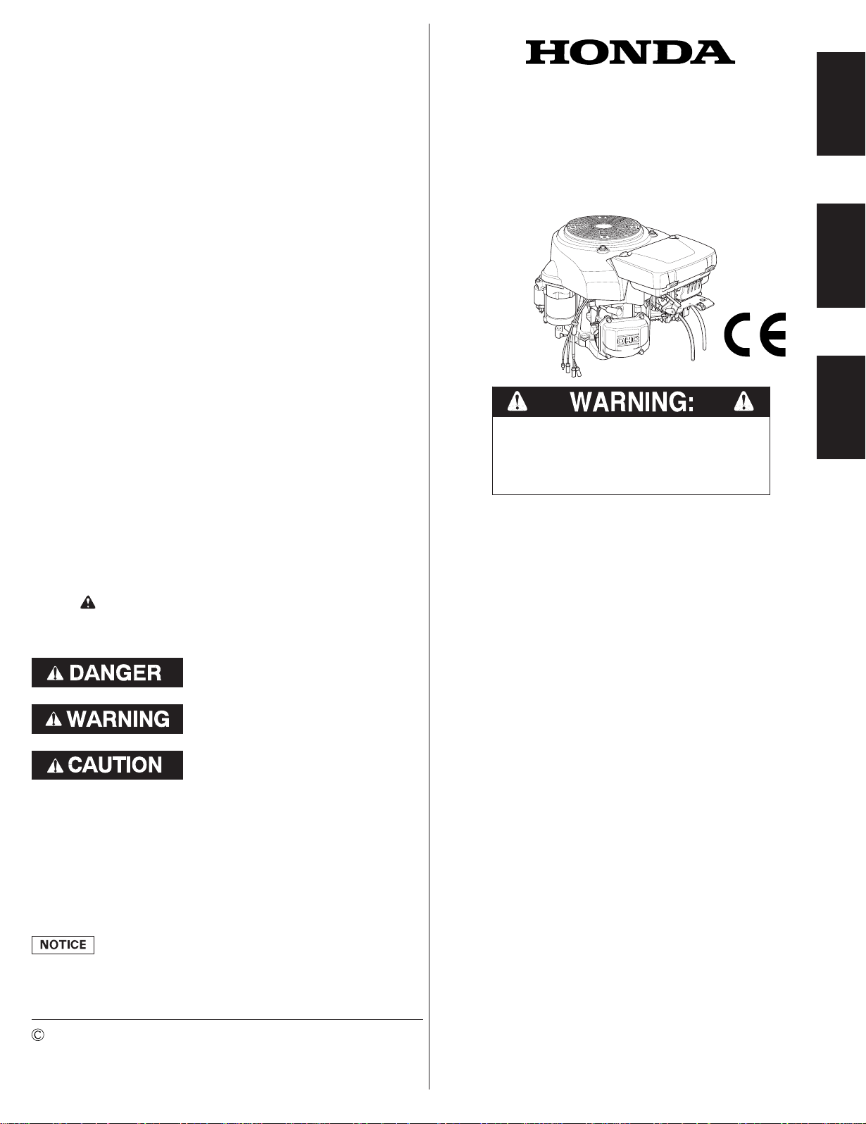
SAFETY MESSAGES
OWNER’S MANUAL
MANUEL DE L’UTILISATEUR
MANUAL DEL PROPIETARIO
GCV520 · GCV530 · GXV520 · GXV530
The engine exhaust from this product
contains chemicals known to the State of
California to cause cancer, birth defects
or other reproductive harm.
ENGLISHFRANÇAISESPAÑOL
Your safety and the safety of others are very important. We have
provided important safety messages in this manual and on the
engine.Please read these messages carefully.
A safety message alerts you to potentialhazards that could hurt
you or others.Each safety message is preceded by a safety alert
symbol and one of three words, DANGER, WARNING, or
CAUTION.
These signal words mean:
You WILL be KILLED or SERIOUSLY
HURT if you don’t follow instructions.
You CAN be KILLED or SERIOUSLY
HURT if you don’t follow instructions.
You CAN be HURT if you don’t follow
instructions.
Each message tells you what the hazard is, what can happen, and
what you can do to avoid or reduce injury.
DAMAGE PREVENTION MESSAGES
You will also see other important messages that are preceded by
the word NOTICE.
This word means:
Your engine or other property can be damaged if you
don’t follow instructions.
The purpose of these messages is to help prevent damage to your
engine, other property, or the environment.
2005 Honda Motor Co., Ltd. All Rights Reserved
GCV520R·GCV530R·GXV530R GCV520U·GCV530U·GXV520U·GXV530U
37Z5Z603
00X37-Z5Z-6030
−
CONTENTS
.......................INTRODUCTION .1
COMPONENT& CONTROL
................................LOCATION .2
................................FEATURES .3
BEFORE OPERATION
....................................CHECKS .3
..............................OPERATION .4
SAFE OPERATING
THE IMPORTANCE OF
MAINTENANCE
............................SCHEDULE .6
...........................REFUELING .7
...........................ENGINE OIL .7
.........................Oil Change .8
.............................OIL FILTER .8
........................AIR CLEANER .9
..........................Inspection .9
............................Cleaning .9
ENGLISH
................SAFETYMESSAGES .1
..........SAFETYINFORMATION .2
.....SAFETYLABEL LOCATION .2
.....................PRECAUTIONS .4
......STARTINGTHE ENGINE .4
......STOPPINGTHE ENGINE .5
.....SETTINGENGINE SPEED .5
.....SERVICING YOUR ENGINE .6
....................MAINTENANCE .6
......MAINTENANCE SAFETY .6
.......SAFETYPRECAUTIONS .6
............RecommendedOil .7
..................Oil Level Check .7
.......................FUEL FILTER .10
.............COOLING SYSTEM .10
......................SPARK PLUG .10
.............SPARK ARRESTER .11
HELPFUL TIPS &
......................SUGGESTIONS .11
...STORING YOUR ENGINE .11
................TRANSPORTING .12
TAKING CARE OF
....UNEXPECTED PROBLEMS .13
TECHNICAL& CONSUMER
.......................INFORMATION .13
.....Serial Number Location .13
Battery Connections for
....................Electric Starter .14
.....Remote Control Linkage .14
Carburetor Modifications for
.....High AltitudeOperation .15
Emission Control System
.........................Information .15
..............................Air Index .16
.....................Specifications .16
........Tuneup Specifications .17
Quick Reference
.........................Information .17
................Wiring Diagrams .17
.CONSUMER INFORMATION .19
DISTRIBUTOR/DEALER
.LOCATOR INFORMATION .19
CUSTOMER SERVICE
...................INFORMATION .19
1
Understand the operation of all controls and learn how to stop
the engine quickly in case of emergency. Make sure the operator
receives adequate instruction before operating the equipment.
Do not allow children to operate the engine. Keep children and
pets away from the area of operation.
Your engine’s exhaust contains poisonous carbon monoxide.
Do not run the engine without adequate ventilation, and never
run the engine indoors.
The engine and exhaust become very hot during operation.
Keep the engineat least 1 meter (3 feet) away from buildings
and other equipment during operation. Keep flammable
materials away, and do not place anything on the engine while it
is running.
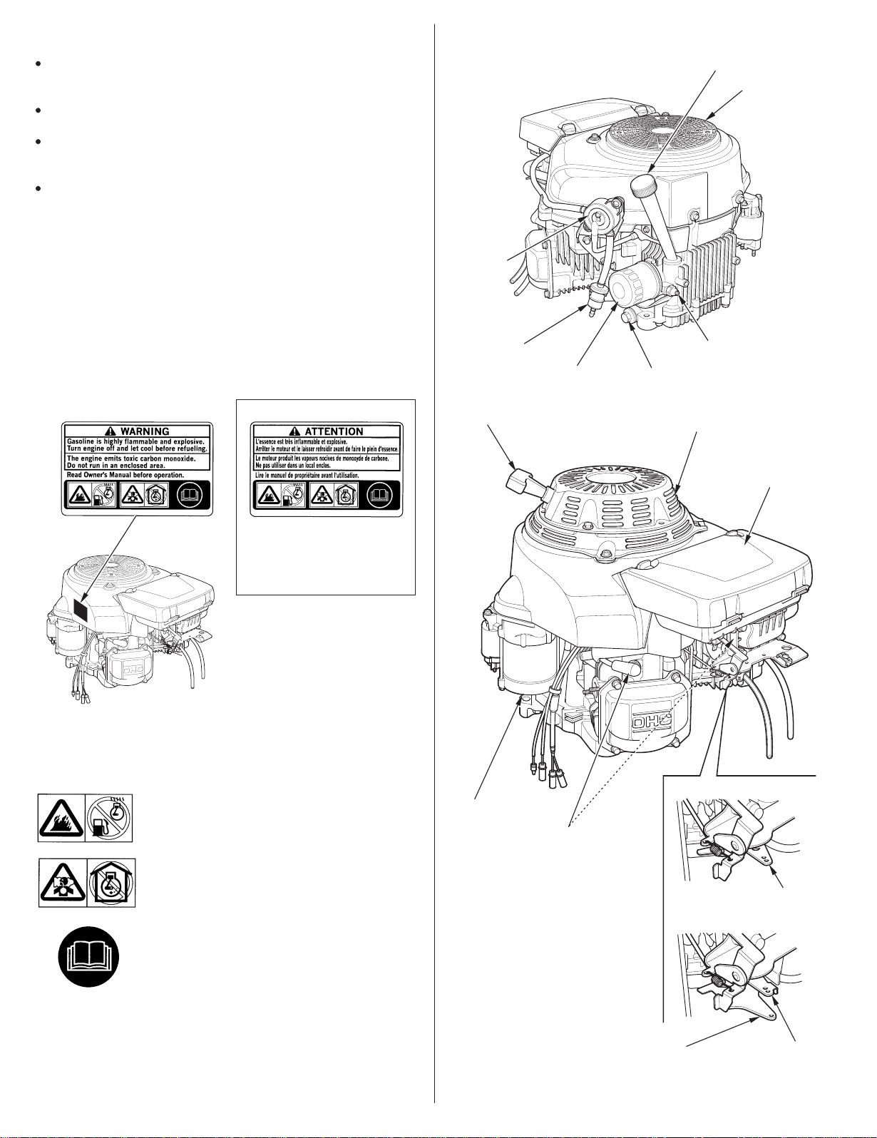
SAFETY LABEL LOCATION
COMPONENT & CONTROL LOCATIONSAFETY INFORMATION
FUEL PUMP
OIL FILLER CAP/
DIPSTICK
SCREEN GRID
This label warns you of potential hazards that can cause serious
injury. Read it carefully.
If the label comes off or becomes hard to read, contact your Honda
dealer for replacement.
For Canada:
French label is packaged
with the engine.
FUEL FILTER
(applicable types)
STARTER GRIP
(applicable types)
OIL FILTER
OIL DRAIN BOLT
RECOIL STARTER
(applicable types)
OIL PRESSURE SWITCH
(applicable types)
AIR CLEANER
Single Lever Type:
Gasoline is highly flammable and explosive.
Turn engine off and let cool before refueling.
ELECTRIC STARTER
SPARK PLUGS
The engine emits toxic poisonous carbon
monoxide gas. Do not run in an enclosed area.
Dual Lever Type:
CONTROL
LEVER
Read Owner’s Manual before operation.
CHOKE
LEVER
2
ENGLISH
THROTTLE
LEVER
BEFORE OPERATION CHECKSFEATURES
Fuel-cut Solenoid
The engine is equipped with a fuel-cut solenoid that allows fuel to
flow to the carburetor main jet when the engine switch is in the ON
or START position and stops the flow of fuel to the main jet when
the engine switch is in the OFF position.
The engine must be connected to the battery to energize the fuelcut solenoid, allowing the engine to run. If the battery is
disconnected, fuel flow to the carburetor main jet will stop.
Oil Pressure Switch (applicable types):
The engine is equipped with an oil pressure switch to prevent
damage from lack of lubrication or overheating.
If the oil pressure alarm lamp comes on, check the engineoil level
and add the correct engine oil if necessary (see page ).
To restart the engine, turn the engine switch to the OFF position.
Next, start according to the starting procedure.
If the oil pressure alarm lamp continuesto light even through the
engineoil level is correct, stop operatingthe engine and see an
authorized Honda servicing dealers.
7
IS YOUR ENGINE READY TO GO?
For your safety, and to maximize the service life of your
equipment, it is very important to take a few moments before you
operate the engine to check its condition. Be sure to take care of
any problem you find, or have your servicing dealer correct it,
before you operate the engine.
Improperly maintaining this engine, or failure to
correct a problem before operation, can cause a
malfunction in which you can be seriously hurt or
killed.
Always perform a pre-operation inspection before
each operation, and correct any problem.
Before beginning your pre-operation checks, be sure the engine is
level and the engine switch is in the OFF position.
Always check the following items before you start the engine:
Check the General Condition of the Engine
1.
Look around and underneath the engine for signs of oil or
gasolineleaks.
2.
Remove any excessive dirt or debris, especially around the
muffler and recoil starter.
Remove any objects or debris that may block the cooling air
3.
intake at the recoil starter/fan cover. Running the engine with a
blocked air intake can cause engine damage.
Look for signs of damage.
4.
Check that all shields and covers are in place, and all nuts, bolts,
5.
and screws are tightened.
Check the Engine
1.
Check the fuel level. Starting with a full tank will help to
eliminate or reduce operating interruptions for refueling.
2.
Check the engine oil level (see page ). Running the engine
with a low oil level can cause engine damage.
Check the air filter element (see page ). A dirty air filter
3.
element will restrict air flow to the carburetor, reducing engine
performance.
Check the Equipment Powered by This Engine
Review the instructions provided with the equipment powered
by this engine for any precautions and procedures that should
be followed before engine startup.
7
9
ENGLISH
3
OPERATION
SAFE OPERATING PRECAUTIONS
Before operating the engine for the first time, please review the
SAFETYINFORMATION
OPERATIONCHECKS
section on page and the
on page .
3
For your safety, do not operate the engine in an enclosed area
such as a garage. Your engine’s exhaust contains poisonous
carbon monoxide gas that can collect rapidly in an enclosed area
and cause illness or death.
Exhaust contains poisonous carbon monoxide gas
that can build up to dangerouslevels in closed areas.
Breathing carbon monoxide can cause
unconsciousness or death.
2
BEFORE
DUAL LEVER TYPE:
To start a cold engine, move the choke lever to the CLOSED
position and move the throttle lever away from the MIN.
position, about 1/3 of the way toward the MAX. position.
CHOKE LEVER
MMAAXX..
CCLLOOSSEEDD
MMIINN..
THROTTLE LEVER
OOPPEENN
Some engine applications use a remote-mounted control rather
than the engine-mounted lever shown here. Refer to the
instructions provided by the equipment manufacturer.
Never run the engine in a closed, or even partly
closed area where people may be present.
Review the instructions provided with the equipment powered by
this engine for any safety precautions that should be observed
with engine startup, shutdown or operation.
STARTING THE ENGINE
If the fuel tank is equipped with a valve, be sure the fuel valve is
1.
in the OPEN or ON position before attempting to start the engine.
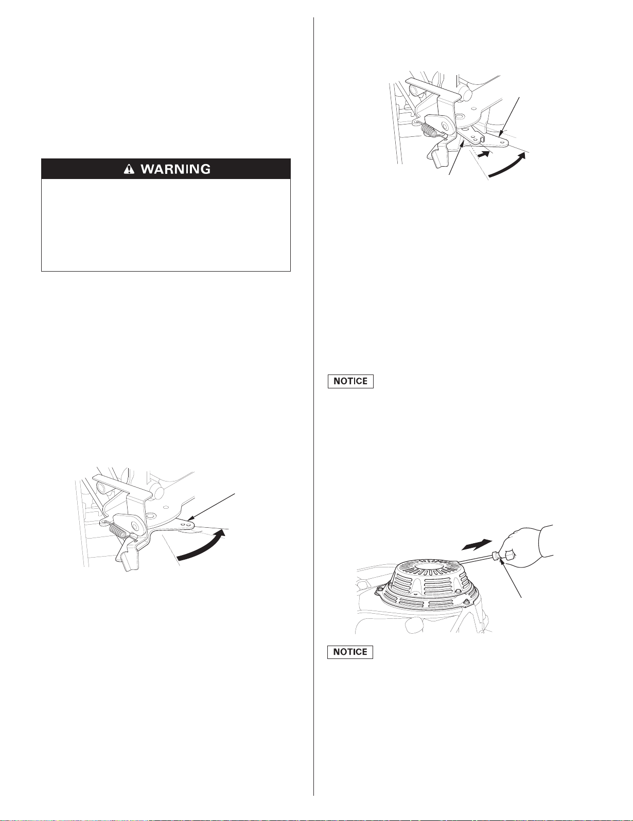
SINGLE LEVER TYPE:
2.
To start a cold engine, move the controllever to the CHOKE
position.
To restart a warm engine, leave the control lever in the MIN.
position.
CONTROL LEVER
CHOKE
MMAAXX..
3.
Turn the engine switch to the ON position.
4.
Operate the starter.
ELECTRIC STARTER:
Turn the key to the START position, and hold it there until the
engine starts.
If the engine fails to start within 5 seconds, release the key, and
wait at least 10 seconds before operating the starter again.
Using the electric starter for more than 5 seconds at a time will
overheat the starter motor and can damage it.
When the engine starts, release the key, allowing it to return to
the ON position.
RECOIL STARTER (applicable types):
Pull the starter grip lightly until you feel resistance, then pull
briskly in the direction of the arrow as shown below. Return the
starter grip gently.
Directiontopull
MMIINN..
STARTER GRIP
Do not allow the starter grip to snap back against the engine.
Return it gently to prevent damage to the starter.
4
ENGLISH
SINGLE LEVER TYPE:
5.
If the controllever has been moved to the CHOKE position to
start the engine, gradually move it to the MIN. position as the
engine warms up.
CCHHOOKKEE
CONTROL LEVER
MMIINN..
DUAL LEVER TYPE:
If the choke lever was moved to the CLOSED position to start the
engine, gradually move it to the OPEN position as the engine
warms up.
STOPPING THE ENGINE
To stop the engine in an emergency, simply turn the engine switch
to the OFF position. Under normal conditions, use the following
procedure. Refer to the instructions provided by the equipment
manufacturer.
1.
Move the control lever (single lever type) or throttle lever (dual
lever type) to the MIN. position.
Some engine applications use a remote-mounted throttle
control rather than the engine-mounted throttle lever shown
here.
SINGLE LEVER TYPE DUAL LEVER TYPE
CHOKE LEVER
OOPPEENN
CCLLOOSSEEDD
MMIINN..
CONTROL LEVER
2.
Turn the engine switch to the OFF position.
3.
If the fuel tank is equipped with a valve, turn the fuel valve to the
THROTTLE LEVER
MMIINN..
CLOSED or OFF position.
SETTING ENGINE SPEED
Positionthe control lever (single lever type) or throttlelever (dual
lever type) for the desired engine speed.
Some engine applications use a remote-mounted control rather
than the engine-mounted lever shown here. Refer to the
instructions provided by the equipment manufacturer.
For engine speed recommendations, refer to the instructions
provided with the equipment powered by this engine.
SINGLE LEVER TYPE DUAL LEVER TYPE
MMAAXX..
MMAAXX..
CONTROL LEVER
MMIINN..
THROTTLE LEVER
Do not disconnect the battery from the engine while the engine is
running. Disconnecting the battery causes the fuel-cut solenoid to
shut off the flow of fuel to the carburetor main jet, and the engine
will stop.
ENGLISH
MMIINN..
5
SERVICING YOUR ENGINE
THE IMPORTANCE OF MAINTENANCE
Good maintenance is essential for safe, economical and troublefree operation. It will also help reduce pollution.
Improper maintenance, or failure to correct a
problem before operation, can cause a malfunction in
which you can be seriously hurt or killed.
Always follow the inspectionand maintenance
recommendations and schedules in this owner’s
manual.
To help you properly care for your engine, the following pages
include a maintenance schedule, routine inspection procedures,
and simple maintenance procedures using basic hand tools. Other
service tasks that are more difficult, or require special tools, are
best handled by professionals and are normally performed by a
Honda technician or other qualified mechanic.
The maintenance schedule applies to normal operating conditions.
If you operate your engine under severe conditions, such as
sustained high-load or high-temperature operation, or use in
unusually wet or dusty conditions, consult your servicing dealer
for recommendations applicable to your individual needs and use.
Maintenance, replacement, or repair of the emission control
devices and systems may be performed by any engine repair
establishment or individual, using parts that are ‘‘certified’’ to
EPA standards.
MAINTENANCE SAFETY
Some of the most important safety precautionsfollow. However,
we cannot warn you of every conceivable hazard that can arise in
performing maintenance. Only you can decide whether or not you
should perform a given task.
Failure to properly follow maintenance instructions
and precautions can cause you to be seriously hurt or
killed.
Always follow the procedures and precautions in this
owner’s manual.
To reduce the possibility of fire or explosion, be careful when
working around gasoline. Use only a non-flammable solvent,
not gasoline, to clean parts. Keep cigarettes, sparks and flames
away from all fuel related parts.
Remember that an authorized Honda servicing dealer knows your
engine best and is fully equipped to maintain and repair it.
To ensure the best quality and reliability, use only new Honda
Genuine parts or their equivalents for repair and replacement.
MAINTENANCE SCHEDULE
Every
Every 6
REGULAR SERVICE PERIOD (3)
Perform at every
indicated month or
operating hour interval,
whichever comes first.
ITEM
Engine oil
Oil filter
()
applicable types
Air cleaner
Spark plugs
Spark arrester
()
applicable types
Cooling system
Idle speed
Valve clearance
Timing belt
Combustion
chamber
Fuel filter
Fuel tube
Replace paper element type only.
*
(1)
Service more frequently when used in dusty areas.
(2)
These items should be serviced by your Honda servicing
Check level
Change
Replace
Check
Clean
Replace
Check-adjust
Replace
Clean
Clean
Check-adjust
Check-adjust
Check
Clean
Check-replace
Check
Each
Use
Every 3
First
Months
Months
Month
or
or
or
100 Hrs
50 Hrs
20 Hrs
(1)
After every 300 Hrs (2)(4)
After every 300 Hrs (2)
Every 2 years
(Replaceif necessary) (2)
Year
or
200 Hrs
*
(2)
(2)
(2)
Refer
to
Page
7
8
8
9
9
10
11
10
Shop
manual
Shop
manual
Shop
manual
Shop
manual
Shop
manual
Shop
manual
dealer, unless you have the proper tools and are mechanically
proficient. Refer to the Honda shop manual for service
procedures.
SAFETY PRECAUTIONS
Make sure the engine is off before you begin any maintenance
or repairs. This will eliminate several potentialhazards:
Carbon monoxide poisoning from engine exhaust.
−
Be sure there is adequate ventilation whenever you operate
the engine.
Burns from hot parts.
−
Let the engine and exhaust system cool before touching.
Injury from moving parts.
−
Do not run the engine unless instructed to do so.
Read the instructionsbeforeyou begin, and make sure you have
the tools and skills required.
6
(3)
For commercial use, log hours of operation to determine
propermaintenanceintervals.
(4)
Check that there is no crack and abnormal wear-out in the belt,
and replace if it is abnormal.
Failure to follow this maintenance schedule could result in nonwarrantablefailures.
ENGLISH
REFUELING
ENGINE OIL
Recommended Fuel
Unleaded gasoline
U.S.
Except U.S.
Pump octane rating 86 or higher
Research octane rating 91 or higher
Pump octane rating 86 or higher
This engine is certified to operate on unleaded gasoline with a
pump octane rating of 86 or higher (a research octane rating of 91
or higher).
Refuel in a well-ventilated area with the engine stopped. If the
engine has been running, allow it to cool first. Never refuel the
engine inside a building where gasoline fumes may reach flames
or sparks.
You may use unleaded gasoline containing no more than 10%
ethanol (E10) or 5% methanol by volume. In addition, methanol
must contain cosolvents and corrosion inhibitors. Use of fuels
with content of ethanol or methanol greater than shown above
may cause starting and/or performance problems. It may also
damage metal, rubber, and plastic parts of the fuel system. Engine
damage or performance problems that result from using a fuel
with percentages of ethanol or methanol greater than shown
above are not covered under warranty.
If your equipment will be used on an infrequent or intermittent
basis, please refer to the fuel section of the HELPFUL TIPS &
SUGGESTIONS chapter (see page ) for additional information
11
regarding fuel deterioration.
Oil is a major factor affecting performance and service life. Use
4-strokeautomotivedetergentoil.
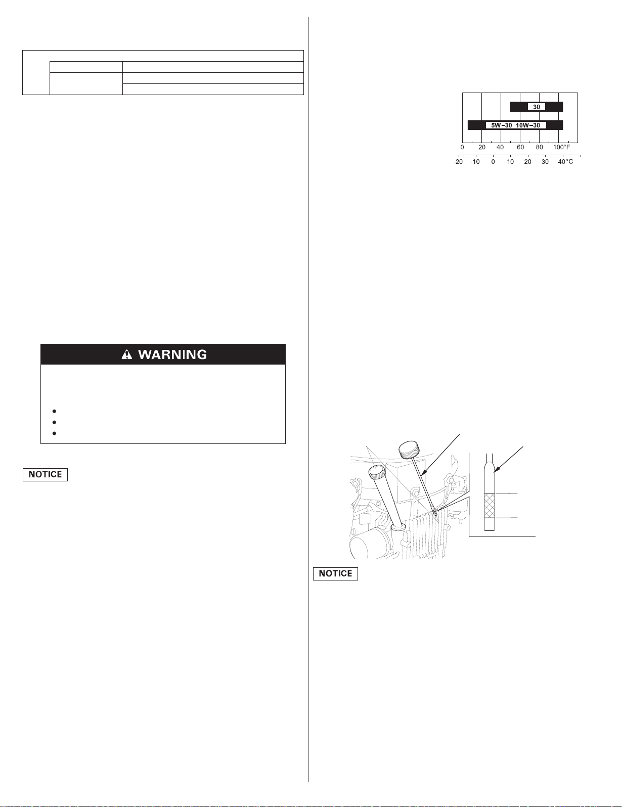
Recommended Oil
Use 4-stroke motor oil that
meets or exceeds the
requirements for API service
categorySJorlater(or
equivalent).Always check the
API service label on the oil
container to be sure it includes
the letters SJ or later (or
AMBIENT TEMPERATURE
equivalent).
SAE 10W-30 is recommended for general use. Other viscosities
shown in the chart may be used when the average temperature in
your area is within the indicated range.
Oil Level Check
Check the engineoil level with the engine stopped and in a level
position.
1.
Remove the oil filler cap/dipstick and wipe it clean.
2.
Insert the oil filler cap/dipstick into the oil filler neck, but do not
screw it in, then remove it to check the oil level.
Gasoline is highly flammable and explosive, and you
can be burned or seriously injured when refueling.
Stop engine and keep heat, sparks, and flame away.
Refuel only outdoors.
Wipe up spills immediately.
Fuel can damage paint and some types of plastic. Be careful not to
spill fuel when filling your fuel tank. Damagecaused by spilled
fuel is not covered under the
Distributor’s Limited Warranty.
Never use stale or contaminatedgasoline or an oil/gasoline
mixture. Avoid getting dirt or water in the fuel tank.
Refuel carefully to avoid spilling fuel. After refueling, tighten the
fuel tank cap securely.
Keep gasoline away from appliance pilot lights, barbecues,
electric appliances, power tools, etc.
Spilled fuel is not only a fire hazard, it causes environmental
damage. Wipe up spills immediately.
If the oil level is near or below the lower limit mark on the
3.
dipstick, fill with the recommended oil to the upper limit mark.
Do not overfill.
4.
Reinstall the oil filler cap/dipstick.
OIL FILLER CAP/DIPSTICK
OIL FILLER CAP/
DIPSTICK
UPPER LIMIT
LOWER LIMIT
Running the engine with a low oil level can cause engine damage.
This type of damage is not covered by the
Distributor’s Limited
Warranty.
ENGLISH
7
Oil Change OIL FILTER (applicable types)
Drain the used oil when the engine is warm. Warm oil drains
quickly and completely.
Place a suitable container below the engine to catch the used oil,
1.
then remove the oil filler cap/dipstick, drain bolt and washer.
Allow the used oil to drain completely, then reinstall the drain
2.
bolt and new washer, and tighten the drain bolt securely.
Please dispose of used motor oil in a manner that is compatible
with the environment. We suggest you take used oil in a sealed
containerto your local recycling center or service station for
reclamation. Do not throw it in the trash, pour it on the ground,
or pour it down a drain.
3.
With the engine in a level position,fill to the upper limit mark on
the dipstick with the recommended oil (see page ).
7
Running the engine with a low oil level can cause engine
damage. This type of damage is not covered by the
Distributor’s
Limited Warranty.
WASHER
UPPER LIMIT
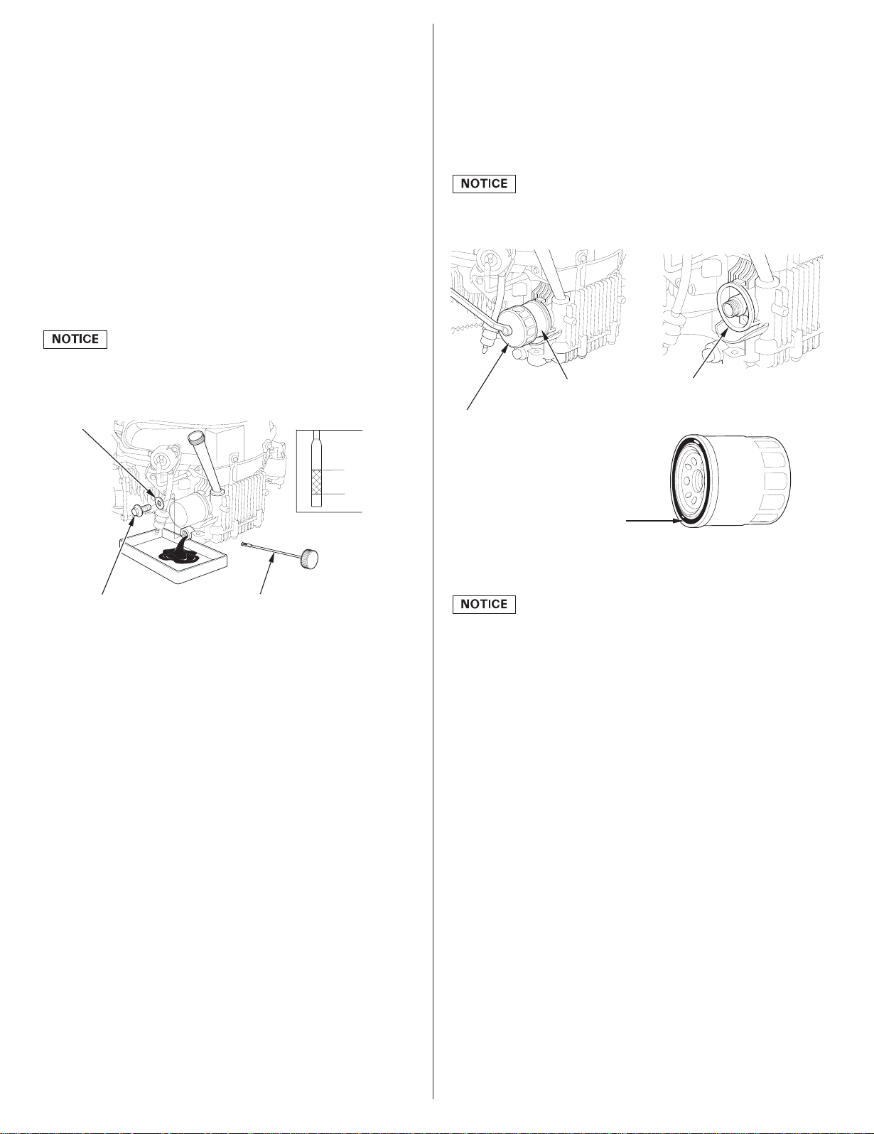
Oil Filter Change
1.
Drain the engine oil, and retighten the drain bolt securely.
2.
Remove the oil filter with an oil filter wrench, and drain the
remaining oil into a suitable container. Dispose the used oil and
filter in a manner compatible with the environment.
Use an oil filter wrench, rather than a strap wrench, to avoid
striking and damaging the oil filter.
OIL FILTER
OIL FILTER WRENCH
FILTER MOUNTING BASE
OIL DRAIN BOLT
Install the oil filler cap/dipstick securely.
4.
OIL FILLER CAP/DIPSTICK
LOWER LIMIT
SEAL
3.
Clean the filter mounting base, and coat the seal of the new oil
filter with clean engine oil.
Use only a Honda Genuine oil filter or a filter of equivalent
quality specified for your model. Using the wrong filter, or a
non-Honda filter which is not of equivalent quality, may cause
engine damage.
4.
Screw on the new oil filter by hand until the seal contacts the
filter mounting base, then use an oil filter wrench to tighten the
filter an additional 7/8 turn.
Oil filter tighteningtorque:
Refill the crankcase with the specified amount of the
5.
recommendedoil (see page ). Reinstall the oil filler cap/
12 N·m (1.2 kgf·m , 9 lbf·ft)
7
dipstick.
Start the engine, and check for leaks.
6.
Stop the engine, and check the oil level as described on page .
7.
If necessary, add oil to bring the oil level to the upper limit mark
on the dipstick.
7
8
ENGLISH
AIR CLEANER
5.
Clean the air filter elements if they are to be reused.
A dirty air cleaner will restrict air flow to the carburetor, reducing
engine performance. If you operate the engine in very dusty areas,
clean the air filter more often thanspecified in the MAINTENANCE
SCHEDULE.
Operating the engine without an air filter, or with a damaged air
filter, will allow dirt to enter the engine, causing rapid engine wear.
This type of damage is not covered by the
Distributor’s Limited
Warranty.
Inspection
Remove the air cleaner cover and inspect the filter elements.
Clean or replace dirty filter elements. Always replace damaged
filter elements.
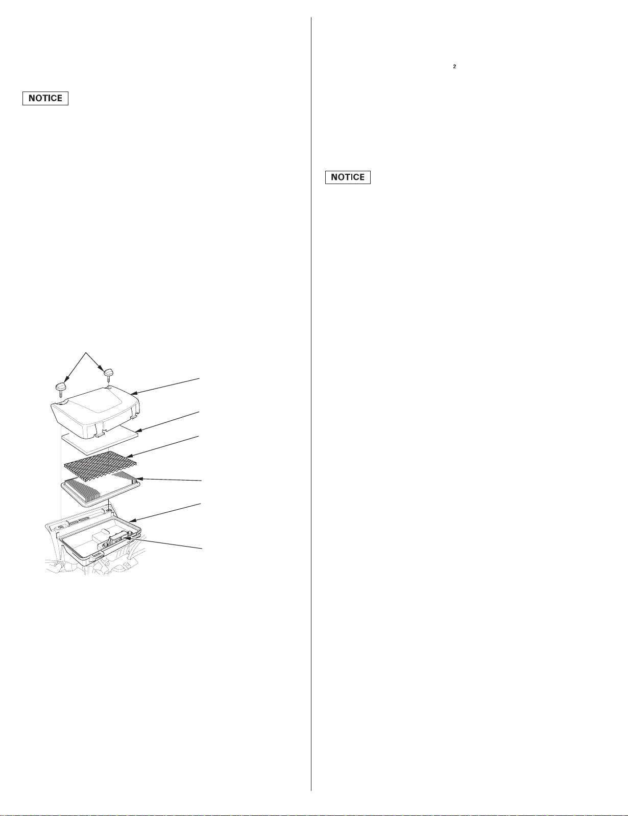
Cleaning
Remove the two air cleaner cover bolts from the air cleaner
1.
cover, and remove the cover.
Remove the foam filter element.
2.
Remove the paper filter element from the grid.
3.
AIR CLEANER COVER BOLTS
AIR CLEANER COVER
Paper air filter element: Tap the filter element several times on a
hard surface to remove dirt, or blow compressed air [not
exceeding 207 kPa (2.1 kgf/cm
, 30 psi)] through the filter
element from the inside. Never try to brush off dirt; brushing will
force dirt into the fibers.
Foam air filter element: Clean in warm soapy water, rinse, and
allow to dry thoroughly. Or clean in non-flammable solvent and
allow to dry. Dip the filter element in clean engine oil, then
squeeze out all excess oil. The engine will smoke when started if
toomuch oil is left in the foam.
Excess oil will restrict air flow through the foam filter element
and may transfer to the paper filter element, soaking and
clogging it.
Wipe dirt from the inside of the air cleaner base and cover, using
6.
a moist rag. Be careful to prevent dirt from entering the air duct
that leads to the carburetor.
7.
Place the foam filter element into the air cleaner cover.
8.
Install the grid over the paper filter element then install the
assembly into the air cleaner base. The grid must be placed
between the foam element and the paper element to prevent oil
from transferring to the paper element.
9.
Install the cover and tighten the two air cleaner cover bolts
securely.
FOAM FILTER ELEMENT
GRID
PAPER FILTER ELEMENT
AIR CLEANER BASE
AIR DUCT
Inspect both air filter elements, and replace themif they are
4.
damaged. Always replace the paper air filter element at the
scheduledinterval (see page ).
6
ENGLISH
9
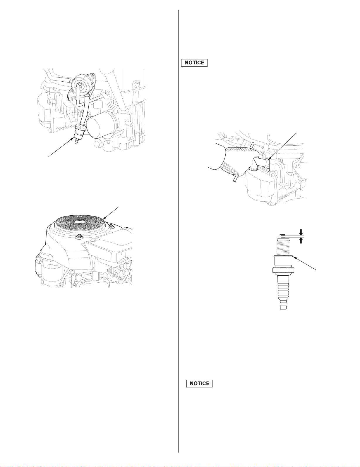
FUEL FILTER
SPARK PLUG
Inspection
Check the fuel filter for water accumulationor sediment.
If the fuel filter is found with excessive water accumulation or
sediment, take the engine to your authorized Honda servicing
dealer.
FUEL FILTER
COOLING SYSTEM
Check the screen grid for blockage and remove the blockage if
necessary.
SCREEN GRID
Recommended Spark Plugs:
BPR5ES (NGK)
W16EPR-U (DENSO)
The recommended spark plugs have the correct heat range for
normal engine operating temperatures.
Incorrect spark plugs can cause engine damage.
For good performance, the spark plugs must be properly gapped
and free of deposits.
Disconnect the spark plug caps, and remove any dirt from
1.
around the spark plug area.
Remove the spark plugs with a 13/16-inch spark plug wrench.
2.
SPARK PLUG WRENCH
Inspect the spark plugs. Replace
3.
them if damaged, badly fouled,
if the sealing washer is in poor
condition, or if the electrode is
worn.
0.7 0.8 mm
−
(0.028 0.031 in)
−
Measure the spark plug
4.
electrode gaps with a wire-type
feeler gauge. Correct the gap, if
necessary, by carefully bending
thesideelectrode.
SEALING
WASHER
The gap should be:
−−
0.7 0.8mm (0.028 0.031 in)
Install the spark plug carefully,
5.
by hand, to avoid crossthreading.
After the spark plug is seated, tighten with a 13/16-inch spark
6.
plug wrench to compress the sealing washer.
When installing a new spark plug, tighten 1/2 turn after the spark
plug seats to compress the washer.
When reinstalling the originalspark plug, tighten1/8 1/4 turn
−
after the spark plug seats to compress the washer.
A loose spark plug can overheat and damage the engine.
Overtightening the spark plug can damage the threads in the
cylinder head.
Attach the spark plug caps to the spark plugs.
7.
10
ENGLISH
SPARK ARRESTER (applicable types)
HELPFUL TIPS & SUGGESTIONS
Your engine is not factory-equipped with a spark arrester. The
spark arrester is optional part. In some areas, it is illegal to operate
an engine without a spark arrester. Check local laws and
regulations. A spark arrester is available from authorized Honda
servicing dealers.
The spark arrester must be serviced every 100 hours to keep it
functioning as designed.
If the engine has been running, the muffler will be hot. Allow it to
cool before servicing the spark arrester.
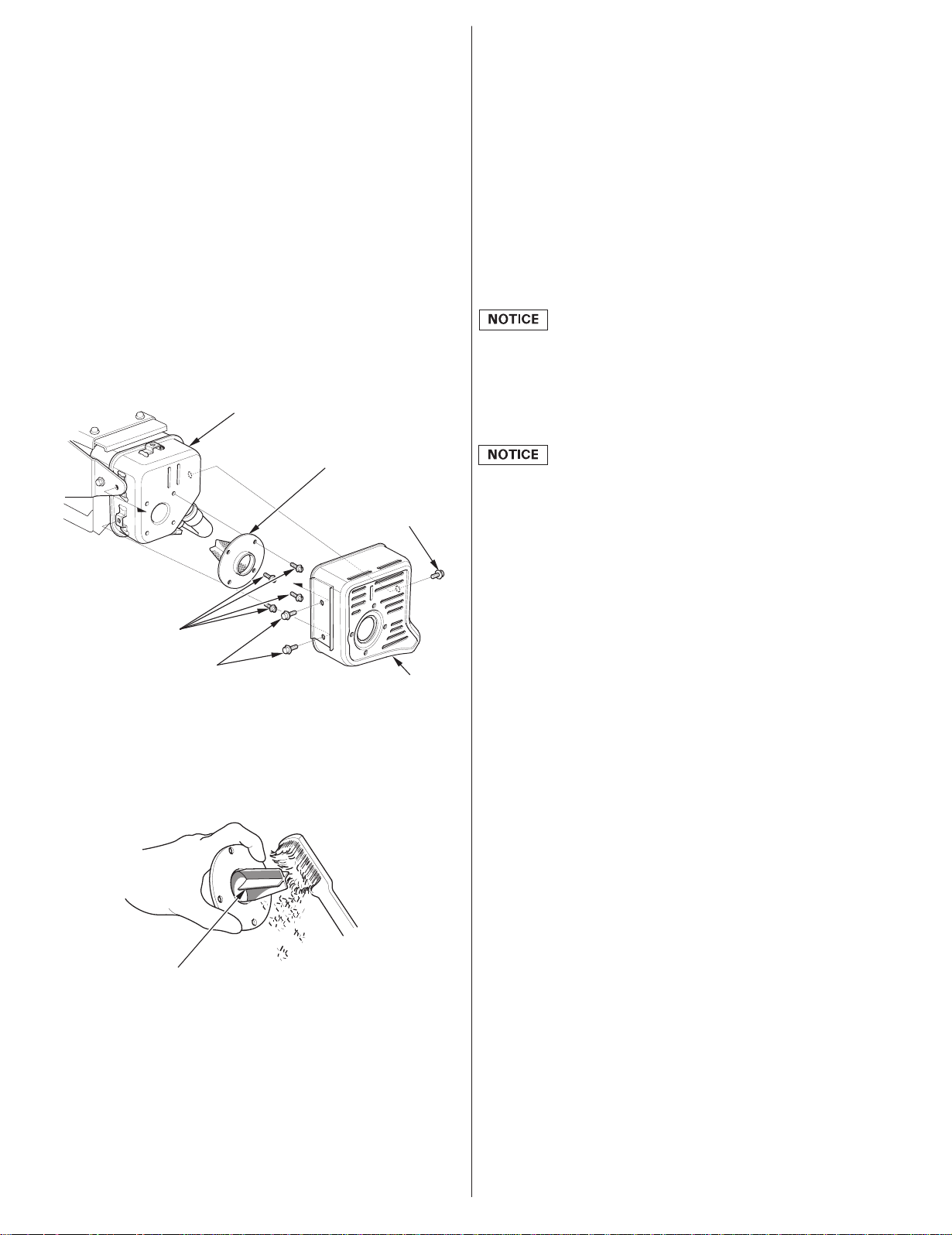
Spark Arrester Cleaning
Remove the three 6 mm flange bolts from the muffler
1.
protector, and remove the muffler protector.
Remove the four special screws from the spark arrester and
2.
remove the spark arrester from the muffler.
MUFFLER
SPARK ARRESTER
6mm
FLANGE BOLT
SPECIAL SCREWS
6mm
FLANGE BOLTS
Use a brush to remove carbon deposits from the spark
3.
MUFFLER
PROTECTOR
arrester screen. Be careful to avoid damagingthe screen.
The spark arrester must be free of breaks and holes. Replace
the spark arrester if it is damaged.
STORING YOUR ENGINE
Storage Preparation
Proper storage preparation is essential for keeping your engine
trouble-free and looking good. The following steps will help to
keep rust and corrosion from impairing your engine’s function and
appearance,and will make the engine easier to start when you use
it again.
Cleaning
If the engine has been running, allow it to cool for at least half an
hour before cleaning. Clean all exterior surfaces, touch up any
damaged paint, and coat other areas that may rust with a light film
of oil.
Using a garden hose or pressure washing equipment can force
water into the air cleaner or muffler opening. Water in the air
cleaner will soak the air filter, and water that passes through the
air filter or muffler can enter the cylinder, causing damage.
Fuel
Depending on the region where you operate your equipment, fuel
formulationsmay deteriorate and oxidize rapidly. Fuel
deterioration and oxidation can occur in as little as 30 days and
may cause damage to the carburetor and/or fuel system. Please
check with your servicing dealer for local storage
recommendations.
Gasoline will oxidizeand deteriorate in storage. Deteriorated
gasoline will cause hard starting, and it leaves gum deposits that
clog the fuel system. If the gasoline in your engine deteriorates
during storage, you may need to have the carburetor and other
fuel system components serviced or replaced.
The length of time that gasoline can be left in your fuel tank and
carburetor without causing functional problems will vary with
such factors as gasoline blend, your storage temperatures, and
whetherthe fuel tank is partially or completely filled. The air in a
partially filled fuel tank promotesfuel deterioration. Very warm
storage temperatures accelerate fuel deterioration. Fuel
deterioration problems may occur within a few months, or even
less if the gasoline was not fresh when you filled the fuel tank.
Fuel system damage or engine performance problems resulting
from neglected storage preparation are not covered under the
Distributor’s Limited Warranty
.
SPARK ARRESTER SCREEN
Install the spark arrester and muffler protector in the reverse
4.
order of disassembly.
You can extend fuel storage life by adding a gasoline stabilizer
that is formulated for that purpose, or you can avoid fuel
deterioration problems by draining the fuel tank and carburetor.
Adding a Gasoline Stabilizer to Extend Fuel Storage Life
When adding a gasoline stabilizer, fill the fuel tank with fresh
gasoline.If only partially filled, air in the tank will promotefuel
deterioration during storage. If you keep a container of gasoline
for refueling, be sure that it contains only fresh gasoline.
Add gasoline stabilizer following the manufacturer’sinstructions.
1.
After adding a gasoline stabilizer, run the engine outdoors for 10
2.
minutesto be sure that treated gasoline has replaced the
untreated gasoline in the carburetor.
Stop the engine, and if the fuel tank is equipped with a fuel
3.
valve, move the fuel valve to the CLOSED or OFF position.
ENGLISH
11
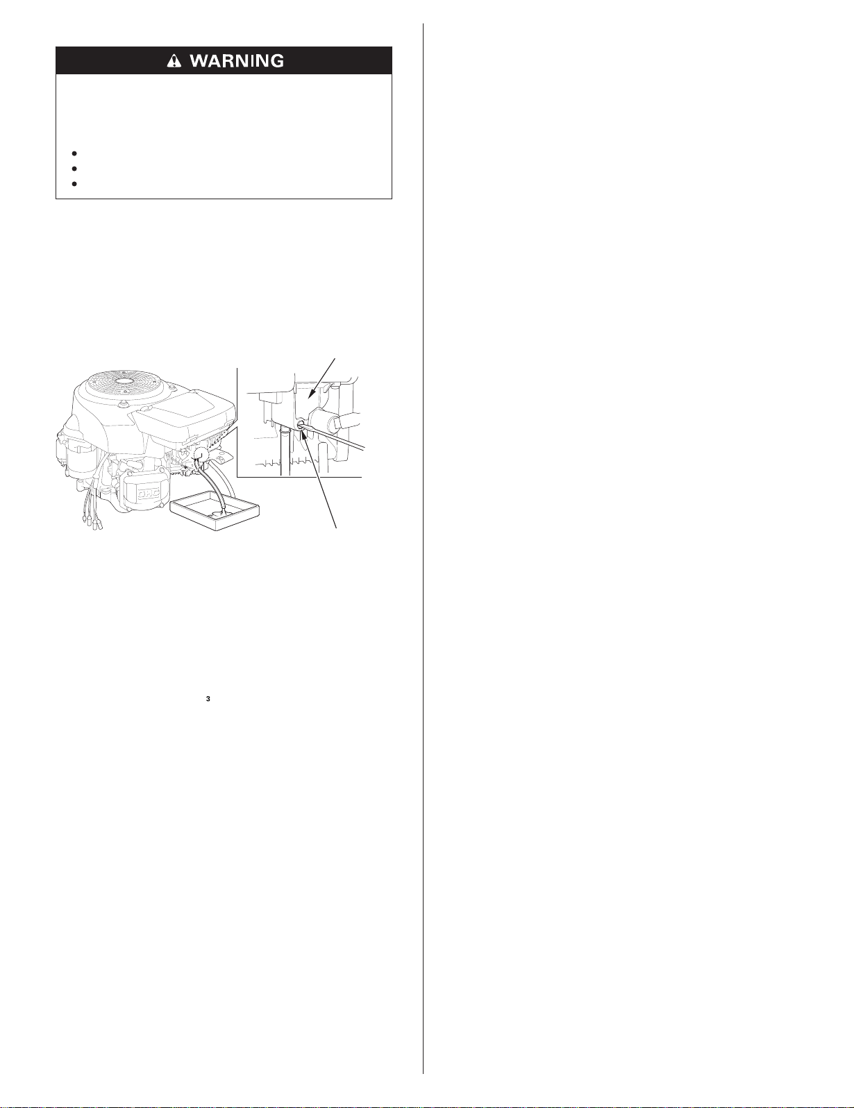
Draining the Fuel Tank and Carburetor
Gasoline is highly flammable and explosive, and you
can be burned or seriously injured when handling
fuel.
Storage Precautions
If your engine will be stored with gasoline in the fuel tank and
carburetor, it is important to reduce the hazard of gasoline vapor
ignition. Select a well-ventilated storage area away from any
appliance that operates with a flame, such as a furnace, water
heater, or clothes dryer. Also avoid any area with a sparkproducing electric motor, or where power tools are operated.
Stop engine and keep heat, sparks, and flame away.
Handle fuel only outdoors.
Wipe up spills immediately.
Disconnect the fuel line to the engine, and drain the fuel tank
1.
into an approved gasoline container. If the fuel tank is
equipped with a valve, turn the fuel valve to the OPEN or ON
position to enable draining. After draining is completed,
reconnect the fuel line.
Loosen the carburetor drain screw, and drain the carburetor
2.
into an approved gasoline container.
CARBURETOR
DRAIN SCREW
After all the fuel has drained into the container, tighten the
3.
drain screw securely.
If possible, avoid storage areas with high humidity, because that
promotes rust and corrosion.
Keep the enginelevel in storage. Tilting can cause fuel or oil
leakage.
With the engine and exhaust system cool, cover the engine to
keep out dust. A hot engine and exhaust system can ignite or melt
some materials. Do not use sheet plastic as a dust cover.
A nonporous cover will trap moisture around the engine,
promoting rust and corrosion.
Remove the battery and store it in a cool, dry place. Recharge the
battery once a month while the engine is in storage. This will help
to extend the service life of the battery.
Removal from Storage
Check your engine as described in the
CHECKS
section of this manual (see page ).
BEFORE OPERATION
3
If the fuel was drained during storage preparation, fill the tank with
fresh gasoline. If you keep a container of gasoline for refueling, be
sure it contains only fresh gasoline. Gasoline oxidizes and
deteriorates over time, causing hard starting.
If the cylinders were coated with oil during storage preparation,
the engine may smoke briefly at startup. This is normal.
TRANSPORTING
Engine Oil
Change the engine oil (see page ).
1.
Remove the spark plugs (see page ).
2.
Pour a tablespoon 5 10 cm
3.
−−
8
10
(5 10 cc) of clean engine oil into
each cylinder.
Turn the engine for a few seconds by turning the engine switch
4.
to the START position to distribute the oil in the cylinders.
Reinstall the spark plugs.
5.
If the engine has been running, allow it to cool for at least 15
minutes before loading the engine-powered equipment on the
transport vehicle. A hot engine and exhaust system can burn you
and can ignite some materials.
Keep the enginelevel whentransportingto reduce the possibility
of fuel leakage. If the fuel tank is equipped with a fuel valve, move
the fuel valve to the CLOSED or OFF position.
12
ENGLISH
TAKING CARE OF UNEXPECTED PROBLEMS TECHNICAL & CONSUMER INFORMATION
ENGINE WILL NOT START
1.
Check battery
and fuse.
2.
Check control
positions.
3.
Check fuel.
4.
Remove and
inspect spark
plugs.
5.
Take engine to
an authorized
Honda
servicing
dealer, or refer
to shop
manual.
Possible Cause Correction TECHNICAL INFORMATION
Battery
discharged.
Fuse burnt out.
Fuel valve OFF.
(If equipped)
Choke OPEN.
Recharge battery.
Replace fuse
Move lever to ON
or OPEN position.
Move lever to
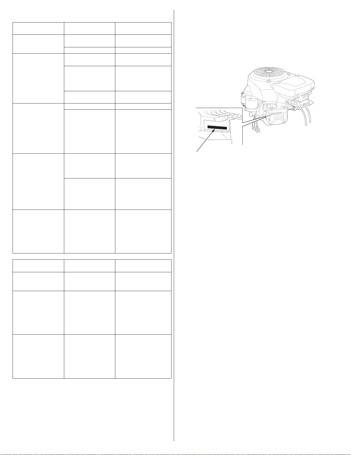
Serial Number Location
Record the engine serial number, type and purchase date in the
space below. You will need this information when ordering parts
and when making technical or warranty inquiries.
CHOKE (CLOSED)
position unless the
engine is warm.
Engine switch
OFF.
Out of fuel.
Bad fuel; engine
stored without
treatingor
draining
Turn engine switch
to ON position.
Refuel (p. 7).
Drain fuel tank and
carburetor (p. 12).
Refuel with fresh
gasoline (p. 7).
gasoline, or
refueled with
bad gasoline.
Spark plug(s)
faulty, fouled, or
improperly
gapped.
Spark plug(s)
wet with fuel
(flooded engine).
Gap or replace
spark plug(s)
(p. 10).
Dry and reinstall
spark plugs. Start
engine with
throttlelever in
SERIAL NUMBER &
ENGINE TYPE LOCATION
Engine serial number: __ __ __ __ __ __ __ __ __ __ __
Engine type: ___ ___ ___ ___
Date Purchased: ______ / ______ / ______
MAX. position.
Fuel filter
restricted,
carburetor
Replace or repair
faulty components
as necessary.
malfunction,
ignition
malfunction,
valves stuck, etc.
−
ENGINE LACKS POWER
1.
Check air filter.
2.
Check fuel.
3.
Take engine to
an authorized
Honda
servicing
dealer, or refer
to shop
manual.
Possible Cause Correction
Filter element(s)
restricted.
Clean or replace
filter element(s)
(p. 9).
Bad fuel; engine
stored without
treatingor
draining
Drain fuel tank and
carburetor (p. 12).
Refuel with fresh
gasoline (p. 7).
gasoline, or
refueled with
bad gasoline.
Fuel filter
restricted,
carburetor
Replace or repair
faulty components
as necessary.
malfunction,
ignition
malfunction,
valves stuck, etc.
ENGLISH
13
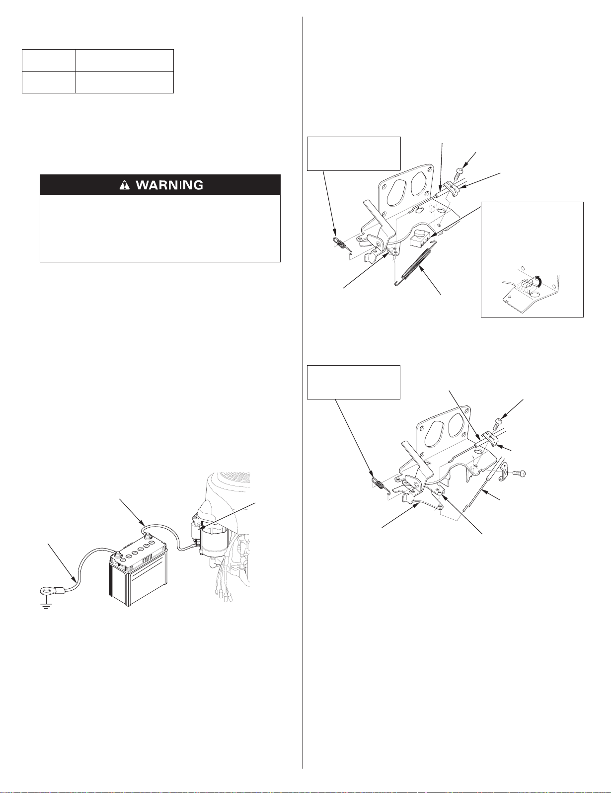
Remote Control LinkageBattery Connections for Electric Starter
Recommended Battery
GCV520
12 V 30 Ah
−
GXV520
GCV530
12 V 30 Ah
−
GXV530
Be careful not to connect the battery in reverse polarity, as this will
short circuit the battery charging system. Always connect the
positive ( ) battery cable to the battery terminal before
connecting the negative ( ) battery cable, so your tools cannot
+
−
cause a short circuit if they touch a grounded part while tightening
the positive ( ) battery cable end.
+
A battery can explode if you do not follow the correct
procedure, seriously injuring anyone nearby.
Keep all sparks, open flames, and smoking materials
away from the battery.
WARNING:
contain lead and lead compounds.
1.
Connect the battery positive ( ) cable to the starter solenoid
Battery posts, terminals, and related accessories
Wash hands after handling.
+
terminal as shown.
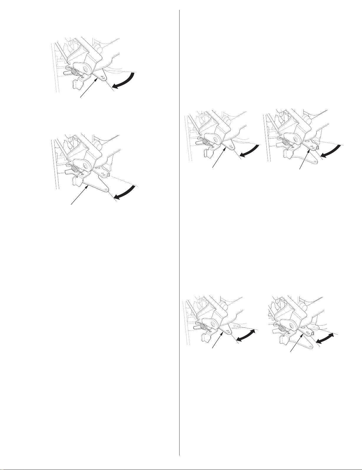
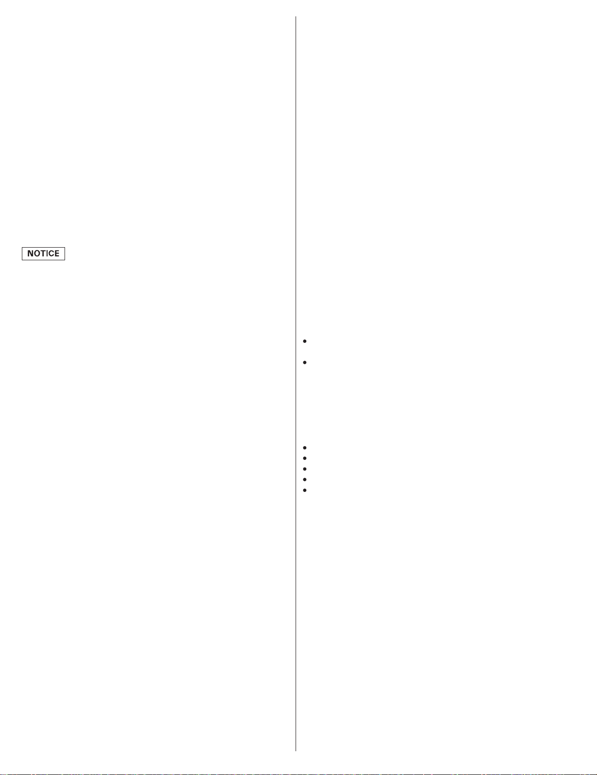
The throttle and choke control levers are provided with holes for
optional cable attachment.
The following illustrations show installation examples for a solid
wire cable. Do not use a braided wire cable.
Single Lever Type:
CHOKE RETURN SPRING
INSTALLATION:
Install with the short
end hook toward the
control base side.
CONTROL LEVER
THROTTLE/CHOKE
CABLE (SOLID WIRE)
LEVER SPRING
×
5 16 mm SCREW
CABLE HOLDER
STOPPER RUBBER
INSTALLATION:
To install the stopper
rubber, first align the boss
with the hole of the
control lever bracket, then
turn the rubber 90° and
secure it to the bracket as
shown.
2.
Connect the battery negative ( ) cable to an engine mounting
−
bolt, frame bolt, or other good engine ground connection.
3.
Connect the battery positive ( ) cable to the battery positive ( )
++
terminal as shown.
4.
Connect the battery negative ( ) cable to the battery negative
−
( ) terminal as shown.
5.
Coat the terminals and cable ends with grease.
BATTERY
POSITIVE ( ) CABLE
BATTERY
NEGATIVE ( ) CABLE
−
+
−
STARTER
SOLENOID
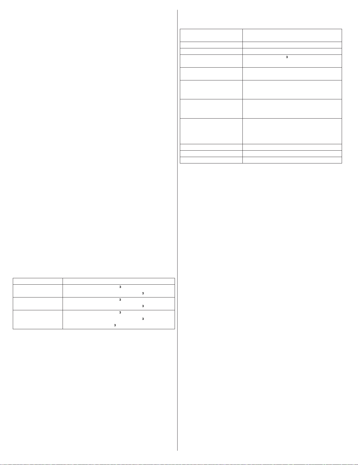
Dual Lever Type:
CHOKE RETURN SPRING
INSTALLATION:
Install with the short
end hook toward the
control base side.
CHOKE LEVER
THROTTLE CABLE
(SOLID WIRE)
×
5 16 mm SCREW (2)
CABLE HOLDER (2)
CHOKE CABLE
(SOLID WIRE)
THROTTLE LEVER
14
ENGLISH
Carburetor Modifications for High Altitude Operation Emission Control System Information
At high altitude, the standard carburetor air-fuel mixture will be
too rich. Performance will decrease, and fuel consumption will
increase. A very rich mixture will also foul the spark plug and
cause hard starting. Operation at an altitude that differs from that
at which this engine was certified, for extended periods of time,
may increase emissions.
High altitude performance can be improved by specific
modifications to the carburetor. If you always operate your engine
at altitudes above 1,500 meters (5,000 feet), have your servicing
dealer perform this carburetor modification. This engine, when
operated at high altitude with the carburetor modifications for
high altitude use, will meet each emission standard throughout its
useful life.
Even with carburetor modification, engine horsepower will
decrease about 3.5% for each 300-meter (1,000-foot)increase in
altitude. The effect of altitude on horsepower will be greater than
this if no carburetor modification is made.
When the carburetor has been modified for high altitude operation,
the air-fuel mixture will be too lean for low altitude use. Operation
at altitudes below 1,500 meters (5,000 feet) with a modified
carburetor may cause the engine to overheat and result in serious
engine damage. For use at low altitudes, have your servicing
dealer return the carburetor to original factory specifications.
Source of Emissions
The combustion process produces carbon monoxide, oxides of
nitrogen, and hydrocarbons. Control of hydrocarbons and oxides
of nitrogen is very important because, under certain conditions,
they react to form photochemical smog when subjected to
sunlight. Carbon monoxide does not react in the same way, but it
is toxic.
Honda utilizes appropriate air/fuel ratios and other emissions
control systems to reduce the emissions of carbon monoxide,
oxides of nitrogen, and hydrocarbons.
Additionally, Honda fuel systems utilize components and control
technologies to reduce evaporative emissions.
The U.S., California Clean Air Acts and Environment Canada
EPA, California and Canadian regulations require all
manufacturers to furnish written instructions describing the
operation and maintenance of emission control systems.
The following instructions and procedures must be followed in
order to keep the emissions from your Honda engine within the
emissionstandards.
Tampering and Altering
Tamperingwith or altering the emission control system may
increase emissions beyond the legal limit. Among those acts that
constitute tampering are:
Removal or alteration of any part of the intake, fuel, or exhaust
systems.
Altering or defeating the governor linkage or speed-adjusting
mechanism to cause the engine to operate outside its design
parameters.
Problems That May Affect Emissions
If you are aware of any of the following symptoms, have your
engine inspected and repaired by your servicing dealer.
Hard starting or stalling after starting.
Rough idle.
Misfiring or backfiring under load.
Afterburning (backfiring).
Black exhaust smoke or high fuel consumption.
ENGLISH
15
The emission control systems on your Honda engine were
designed, built, and certified to conform with EPA, California
(models certified for sale in California), and Canadian emission
regulations. We recommend the use of Honda Genuine parts
whenever you have maintenance done. These original-design
replacementparts are manufacturedto the same standards as the
original parts, so you can be confident of their performance. The
use of replacement parts that are not of the original design and
quality may impair the effectiveness of your emission control
system.
A manufacturer of an aftermarket part assumes the responsibility
that the part will not adversely affect emission performance. The
manufacturer or rebuilder of the part must certify that use of the
part will not result in a failure of the engine to comply with
emission regulations.
Maintenance
Follow the maintenance schedule on page . Remember that this
schedule is based on the assumption that your machine will be
used for its designed purpose. Sustained high-load or hightemperature operation, or use in unusually wet or dusty conditions,
will require more frequent service.
SpecificationsReplacement Parts
GCV520/GXV520 (QEA-1 type)
Length Width
××
Height
Dry mass [weight]
Engine type
4-stroke, overhead camshaft, 2 cylinders (90° V-Twin)
Displacement
[Bore Stroke]
×
Net power
(in accordance with SAE J1349 )
9.8 kW (13.3 PS, 13.1 bhp) at 3,600 rpm
*
Max. Net torque
(GCV520U)
(in accordance with SAE J1349 )
*
Max. Net torque
(GXV520U)
(in accordance with SAE J1349 )
*
Engine oil capacity
Coolingsystem
Ignition system
PTO shaft rotation
458 427 331mm
××
(18.016.813.0in)
××
30.5 kg (67.2 lbs)
530 cm
××
[77.0 57.0 mm (3.03 2.24in)]
(32.3 cu-in)
33.2 N·m (3.39 kgf·m, 24.5 lbf·ft)
at 2,500 rpm
32.9 N·m (3.35 kgf·m, 24.3 lbf·ft)
at 2,500 rpm
Without oil filter replacement:
0.90 L (0.95 US qt, 0.79 lmp qt)
With oil filter replacement:6
1.00 L (1.06 US qt, 0.88 lmp qt)
Forced air
Transistor magneto
Counterclockwise
Air Index
(Modelscertified for sale in California)
An Air Index Information label is applied to engines certified to an
emission durability time period in accordance withthe
requirements of the California Air Resources Board.
The bar graphis intendedto provide you, our customer, the ability
to compare the emissions performance of available engines. The
lower the Air Index, the less pollution.
The durability description is intendedto provide you with
informationrelatingto the engine’s emission durability period.
The descriptive term indicates the useful life period for the engine’s
emission control system. See your
Warranty
for additional information.
Emission Control System
Descriptive Term Applicable to Emissions Durability Period
Moderate
Intermediate
Extended
50 hours [0 80 cm
125 hours [greater than 80 cm
125 hours [0 80 cm
250 hours [greater than 80 cm
300 hours [0 80 cm
500 hours [greater than 80 cm
1,000 hours [225 cm
−−
(0 80cc) inclusive]
(80 cc)]
−−
(0 80cc) inclusive]
(80 cc)]
−−
(0 80cc) inclusive]
(80 cc)]
(225 cc) and greater]
*
The power rating of the engine indicated in this document is the
net power output tested on a production engine for the engine
model and measured in accordance with SAE J1349 at 3,600
rpm (Net Power) and at 2,500 rpm (Max. Net Torque). Mass
production engines may vary from this value.
Actual power output for the engine installed in the final machine
will vary depending on numerous factors, including the
operating speed of the engine in application, environmental
conditions, maintenance, and other variables.
16
ENGLISH
GCV530/GXV530
Length Width
××
Height
Dry mass [weight]
Engine type
Displacement
[Bore Stroke]
×
Net power
(in accordance with SAE J1349 )
Max. Net torque
(GCV530)
(in accordance with SAE J1349 )
Max. Net torque
(GXV530)
(in accordance with SAE J1349 )
Engine oil capacity
(QEA-1 type)
4-stroke, overhead camshaft, 2 cylinders (90° V-Twin)
11.3 kW (15.4 PS, 15.2 bhp) at 3,600 rpm
*
*
*
458 427 331 mm
××
(18.0 16.8 13.0 in)
××
30.5 kg (67.2 lbs)
530 cm
××
[77.0 57.0 mm (3.03 2.24 in)]
(32.3 cu-in)
34.3 N·m (3.50 kgf·m, 25.3 lbf·ft)
at 2,500 rpm
34.2 N·m (3.49 kgf·m, 25.2 lbf·ft)
at 2,500 rpm
Without oil filter replacement:
0.90 L (0.95 US qt, 0.79 lmp qt)
With oil filter replacement:
1.00 L (1.06 US qt, 0.88 lmp qt)
Coolingsystem
Ignition system
PTO shaft rotation
*
The power rating of the engine indicated in this document is the
Forced air
Transistor magneto
Counterclockwise
net power output tested on a production engine for the engine
model and measured in accordance with SAE J1349 at 3,600
rpm (Net Power) and at 2,500 rpm (Max. Net Torque).Mass
production engines may vary from this value.
Actual power output for the engine installed in the final machine
will vary depending on numerous factors, including the
operating speed of the engine in application, environmental
conditions, maintenance, and other variables.
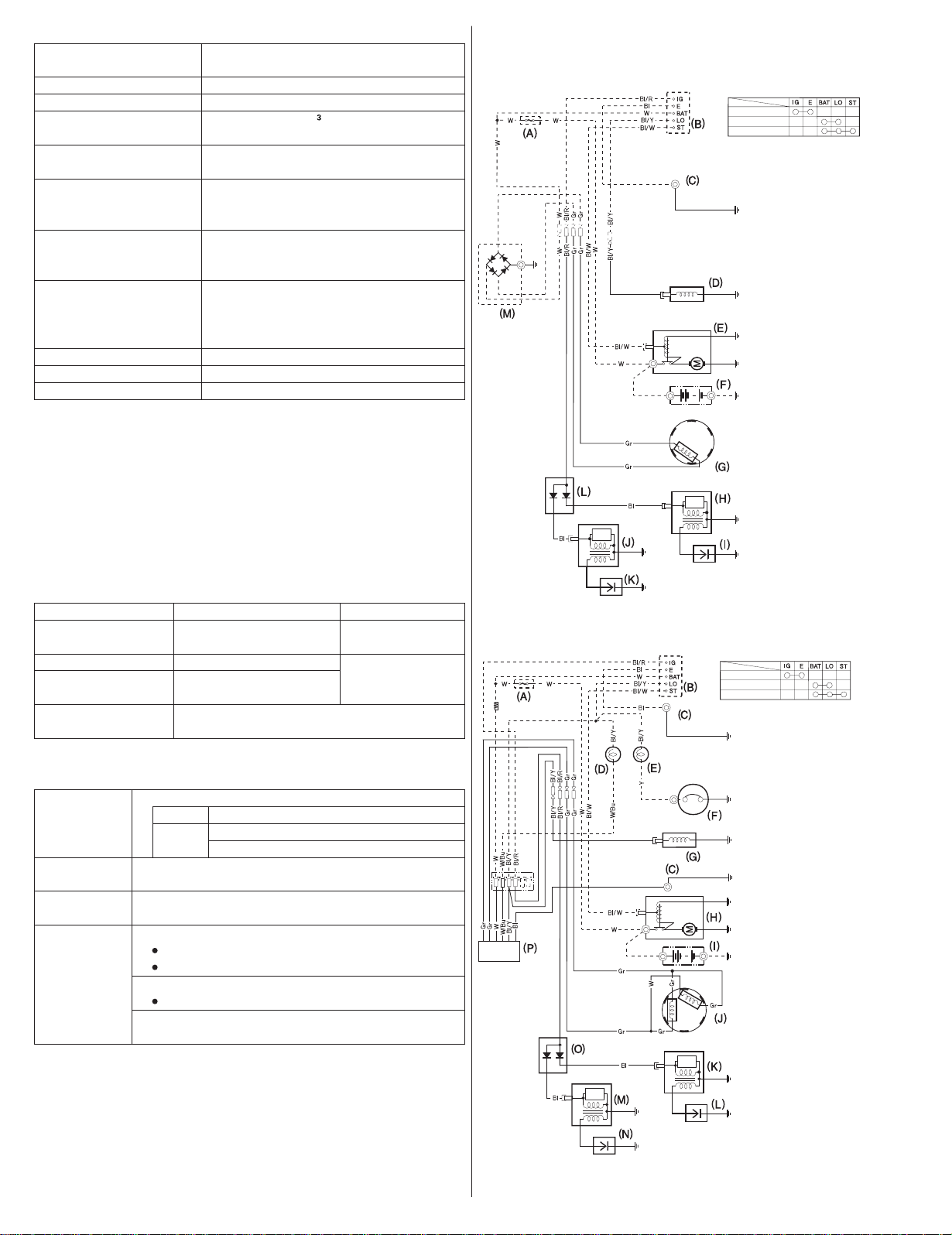
Wiring Diagrams
With 3A Charge coil
ON
OFF
START
Black
Bl
Yellow
Y
Blue
Bu
Green
G
Red
R
White
W
(A)
MAIN FUSE (25 A)
(B)
ENGINE SWITCH
(C)
ENGINE GROUND
(D)
FUEL CUT SOLENOID
STARTER MOTOR
(E)
(F)
BATTERY
3A CHARGE COIL
(G)
(H)
No.2 IGNITION COIL
SPARK PLUG
(I)
(J)
No.1 IGNITION COIL
(K)
SPARK PLUG
(L)
ENGINE STOP DIODE
RECTIFIER
(M)
Br
Brown
O
Orange
Light blue
Lb
Light green
Lg
P
Pink
Gray
Gr
Tuneup Specifications
GCV520/530, GXV520/530
ITEM
Spark plug gap
0.7 0.8mm
−
(0.028 0.031in)
Idle speed
Valve clearance
(cold)
1,400 rpm
IN: 0.10 0.04 mm
EX: 0.15 0.04 mm
Other
specifications
Quick Reference Information
Unleaded gasoline (Refer to page 7)Fuel
U.S.
Except
U.S.
Engine oil
SAE 10W-30, API SJ or later, for general use.
Refer to page 7.
Spark plug
BPR5ES (NGK)
W16EPR-U (DENSO)
Maintenance
Before each use:
Check engine oil level. Refer to page 7.
Check air filter. Refer to page 9.
First 20 hours:
Change engine oil. Refer to page 8.
Subsequent:
Refer to the maintenance schedule on page 6.
MAINTENANCESPECIFICATION
Refer to page 10.
−
+
200
−
150
±
±
See your
authorized
Honda dealer
No other adjustments needed.
Pump octane rating 86 or higher
Research octane rating 91 or higher
Pump octane rating 86 or higher
With 12A Charge coil
OFF
ON
START
Black
Bl
Yellow
Y
Blue
Bu
G
Green
R
Red
White
W
MAIN FUSE (25 A)
(A)
ENGINE SWITCH
(B)
ENGINE GROUND
(C)
CHARGE LAMP
(D)
OIL PRESSURE ALARM
(E)
LAMP
OIL PRESSURE SWITCH
(F)
FUEL CUT SOLENOID
(G)
STARTER MOTOR
(H)
BATTERY
(I)
12A CHARGE COIL
(J)
No.2 IGNITION COIL
(K)
SPARK PLUG
(L)
(M)
No.1 IGNITION COIL
SPARK PLUG
(N)
ENGINE STOP DIODE
(O)
REGULATOR/RECTIFIER
(P)
Br
Brown
O
Orange
Light blue
Lb
Lg
Light green
P
Pink
Gray
Gr
ENGLISH
17
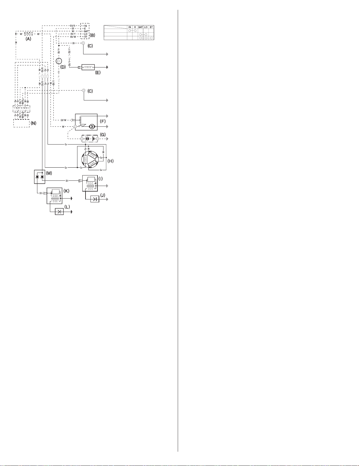
With 18A Charge coil
OFF
ON
START
Black
Bl
Yellow
Y
Blue
Bu
G
Green
R
Red
White
W
MAIN FUSE (25 A)
(A)
ENGINE SWITCH
(B)
ENGINE GROUND
(C)
CHARGE LAMP
(D)
FUEL CUT SOLENOID
(E)
SATARTER MOTOR
(F)
BATTERY
(G)
18A CHARGE COIL
(H)
No.2 IGNITION COIL
(I)
SPARK PLUG
(J)
No.1 IGNITION COIL
(K)
SPARK PLUG
(L)
ENGINE STOP DIODE
(M)
RECTIFIER
(N)
Br
Brown
Orange
O
Light blue
Lb
Lg
Light green
P
Pink
Gray
Gr
18
ENGLISH
 Loading...