

Honda EU2200I User Manual
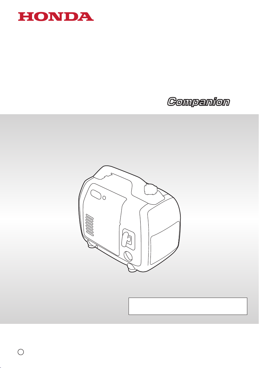
Owner’s Manual
GENERATOR
EU2200i / EU2200i
CompanionCompanion
See page 89 for Initial Use Instructions
C
2018 Honda Motor Co., Ltd. -All Rights Reserved
The engine exhaust from this product
contains chemicals known to the State
of California to cause cancer, birth
defects, or other reproductive harm.
California Proposition 65
This product contains or emits
chemicals known to the state of
California to cause cancer, birth defects
or other reproductive harm
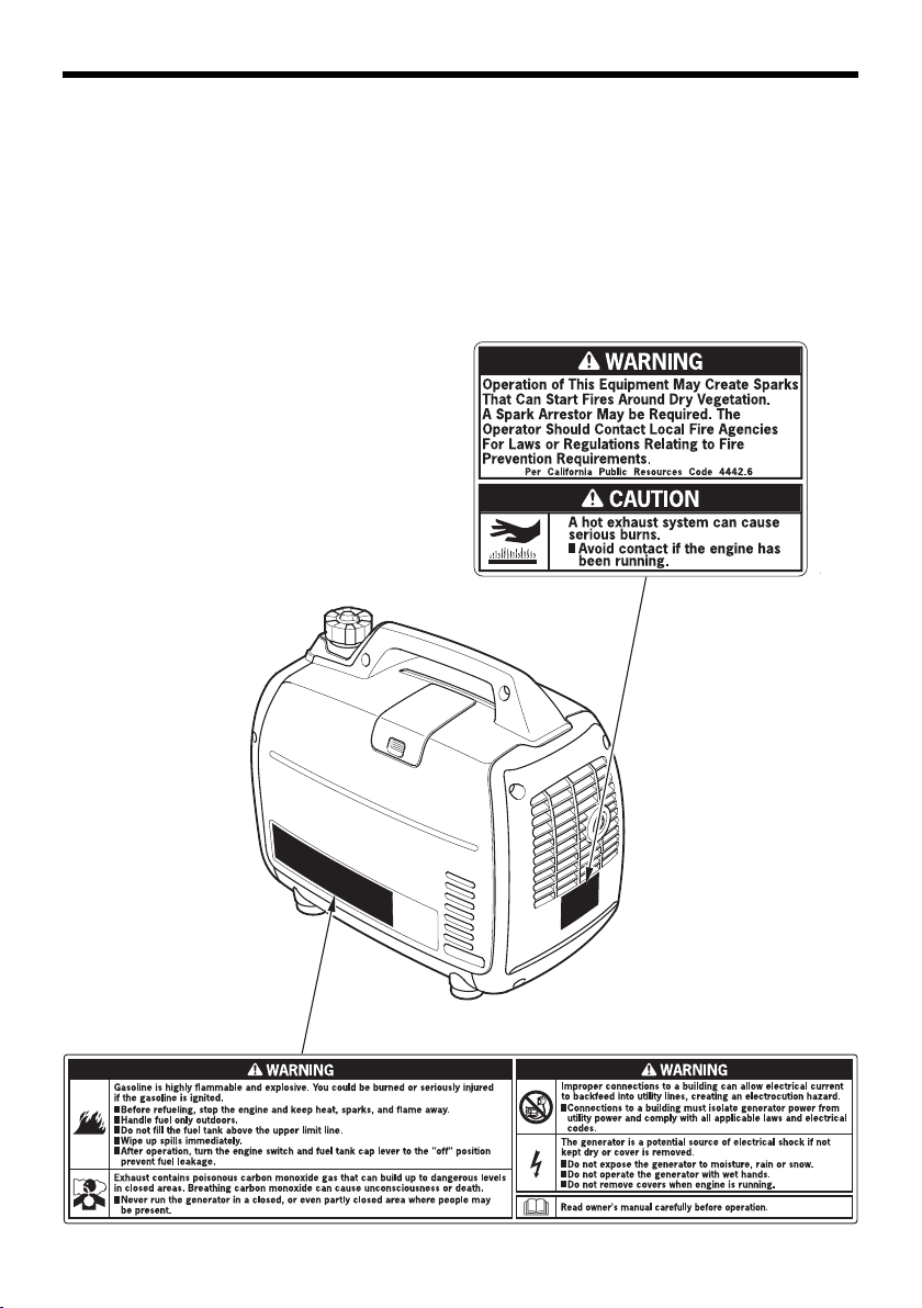
Exhaust contains poisonous carbon
monoxide gas that can build up to
dangerous levels in closed areas.
Breathing carbon monoxide can
cause unconsciousness or death.
Never run the generator in a closed,
or even partly closed area where
people may be present.
Keep this owner’s manual handy, so that you can refer to it any time.
This owner’s manual is considered a permanent part of the generator
and should remain with the generator if resold.
The information and specifications included in this publication were in
effect at the time of approval for printing. Honda Motor Co., Ltd.
reserves the right, however, to discontinue or change specifications or
design at any time without notice and without incurring any obligation
whatsoever.

INTRODUCTION
Congratulations on your selection of a Honda generator. We are certain
you will be pleased with your purchase of one of the finest generators
on the market.
We want to help you get the best results from your new generator and
to operate it safely. This manual contains the information on how to
do that; please read it carefully.
As you read this manual, you will find information preceded by a
symbol. That information is intended to help you avoid
damage to your generator, other property, or the environment.
We suggest you read the Distributor’s Limited Warranty (see page 79)
to fully understand its coverage and your responsibilities of ownership.
When your generator needs scheduled maintenance, keep in mind that
your Honda servicing dealer is specially trained in servicing Honda
generators and is supported by the parts and service divisions of
American Honda. Your Honda servicing dealer is dedicated to your
satisfaction and will be pleased to answer your questions and
concerns.
Best Wishes,
Honda Motor Co., Ltd.
1
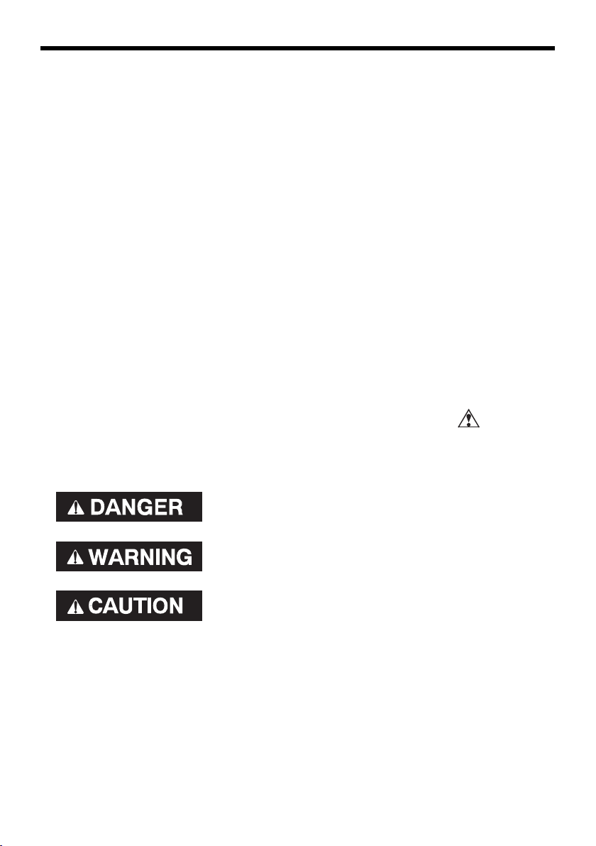
A FEW WORDS ABOUT SAFETY
Your safety and the safety of others are very important. And using this
generator safely is an important responsibility.
To help you make informed decisions about safety, we have provided
operating procedures and other information on labels and in this
manual. This information alerts you to potential hazards that could
hurt you or others.
Of course, it is not practical or possible to warn you about all the
hazards associated with operating or maintaining a generator. You
must use your own good judgment.
You will find important safety information in a variety of forms,
including:
• Safety Labels — on the generator.
• Safety Messages — preceded by a safety alert symbol and one
of three signal words, DANGER, WARNING, or CAUTION.
These signal words mean:
You WILL be KILLED or SERIOUSLY HURT if
you don’t follow instructions.
You CAN be KILLED or SERIOUSLY HURT if
you don’t follow instructions.
You CAN be HURT if you don’t follow
instructions.
• Safety Headings — such as
• Safety Section — such as
• Instructions — how to use this generator correctly and safely.
This entire book is filled with important safety information — please
read it carefully.
The illustrations in this manual are based on: A type
IMPORTANT SAFETY INFORMATION
GENERATOR SAFETY
.
.
2

CONTENTS
GENERATOR SAFETY ...............................................................................6
IMPORTANT SAFETY INFORMATION .................................................6
Operator Responsibility.....................................................................6
Carbon Monoxide Hazards................................................................6
Electric Shock Hazards ......................................................................7
Fire and Burn Hazards .......................................................................7
Refuel With Care ................................................................................8
SAFETY LABEL LOCATIONS.................................................................9
CONTROLS & FEATURES.......................................................................11
COMPONENT & CONTROL LOCATIONS...........................................11
CONTROLS...........................................................................................13
Engine Switch ..................................................................................13
Starter Grip.......................................................................................13
Fuel Filler Cap Vent Lever ...............................................................14
Choke Lever......................................................................................14
Eco Throttle
Parallel Operation Outlets ...............................................................15
AC Circuit Protector .........................................................................16
DC Receptacle [A, A2 types]............................................................17
DC Circuit Protector [A, A2 types] ..................................................17
FEATURES............................................................................................18
Ground Terminal..............................................................................18
Output Indicator ...............................................................................19
Overload Alarm (Indicator) .............................................................20
Oil Alert
LED Light Patterns ...........................................................................21
®
Switch .......................................................................15
®
Indicator...........................................................................20
BEFORE OPERATION ..............................................................................22
ARE YOU READY TO GET STARTED?................................................22
Knowledge........................................................................................22
IS YOUR GENERATOR READY TO GO?.............................................22
Check the Engine .............................................................................23
3

CONTENTS
OPERATION .............................................................................................24
SAFE OPERATING PRECAUTIONS.....................................................24
STARTING THE ENGINE .....................................................................25
STOPPING THE ENGINE .....................................................................28
AC OPERATION....................................................................................30
AC Applications................................................................................32
AC PARALLEL OPERATION.................................................................33
AC Parallel Operation Applications ................................................36
DC OPERATION [A, A2 types].............................................................38
ECO THROTTLE
STANDBY POWER...............................................................................42
Connections to a Building’s Electrical System ..............................42
System Ground ................................................................................42
Special Requirements......................................................................43
SERVICING YOUR GENERATOR............................................................44
THE IMPORTANCE OF MAINTENANCE.............................................44
MAINTENANCE SAFETY.....................................................................45
Safety Precautions ...........................................................................45
MAINTENANCE SCHEDULE ...............................................................46
REFUELING ..........................................................................................47
FUEL RECOMMENDATIONS...............................................................48
ENGINE OIL LEVEL CHECK .................................................................49
ENGINE OIL CHANGE..........................................................................50
ENGINE OIL RECOMMENDATIONS...................................................51
AIR CLEANER SERVICE.......................................................................52
MAIN AND OUTER FILTER CLEANING..............................................54
SPARK PLUG SERVICE........................................................................55
SPARK ARRESTER SERVICE...............................................................57
®
SYSTEM .................................................................41
STORAGE.................................................................................................59
STORAGE PREPARATION...................................................................59
Cleaning............................................................................................59
Fuel....................................................................................................59
Engine Oil .........................................................................................63
Engine Cylinder................................................................................63
STORAGE PRECAUTIONS ..................................................................64
REMOVAL FROM STORAGE...............................................................64
4

CONTENTS
TRANSPORTING......................................................................................65
TAKING CARE OF UNEXPECTED PROBLEMS ......................................66
ENGINE WILL NOT START..................................................................66
ENGINE LACKS POWER......................................................................67
NO POWER AT THE AC RECEPTACLES.............................................68
NO POWER AT THE DC RECEPTACLES.............................................68
TECHNICAL INFORMATION ...................................................................69
Serial Number Location ......................................................................69
Carburetor Modification for High Altitude Operation.......................70
Emission Control System Information...............................................71
Air Index ...............................................................................................73
Specifications.......................................................................................74
Wiring Diagram....................................................................................75
CONSUMER INFORMATION ..................................................................77
Dealer Locator Information.................................................................77
Honda Publications..............................................................................77
Customer Service Information ...........................................................78
Distributor’s Limited Warranty ...........................................................79
Honda Parts, Accessories, and Apparel.............................................82
Emission Control System Warranty...................................................84
INITIAL USE INSTRUCTIONS .................................................................89
ENGINE OIL..........................................................................................89
FUEL......................................................................................................90
BEFORE OPERATION...........................................................................92
REGISTRATION....................................................................................92
INDEX .......................................................................................................93
QUICK REFERENCE INFORMATION ............................ Inside back cover
5

GENERATOR SAFETY
IMPORTANT SAFETY INFORMATION
Honda generators are designed for use with electrical equipment that
has suitable power requirements. Other uses can result in injury to the
operator or damage to the generator and other property.
Most injuries or property damage can be prevented if you follow all
the instructions in this manual and on the generator. The most
common hazards are discussed below, along with the best way to
protect yourself and others.
Operator Responsibility
• Know how to stop the generator quickly in case of emergency.
• Understand the use of all generator controls, output receptacles,
and connections.
• Be sure that anyone who operates the generator receives proper
instruction. Do not let children operate the generator without
parental supervision.
Carbon Monoxide Hazards
A generator's exhaust contains toxic carbon monoxide, which you
cannot see or smell. Breathing carbon monoxide can KILL YOU IN
MINUTES. To avoid carbon monoxide poisoning, follow these
instructions when operating a generator:
• Only run a generator OUTSIDE, far away from windows, doors, and
vents.
• Never operate a generator inside a house, garage, basement, crawl
space, or any enclosed or partially enclosed space.
• Never operate a generator near open doors or windows.
• Get fresh air and seek medical attention immediately if you suspect
you have inhaled carbon monoxide.
Early symptoms of carbon monoxide exposure include headache,
fatigue, shortness of breath, nausea, and dizziness. Continued
exposure to carbon monoxide can cause loss of muscular
coordination, loss of consciousness, and then death.
To alert you to potentially dangerous levels of carbon monoxide
coming from a generator operating outside or from other sources,
install battery operated carbon monoxide alarms or plug-in carbon
monoxide alarms with battery back-up on every level of the home and
outside sleeping areas, according to the manufacturer's instructions.
6

GENERATOR SAFETY
Electric Shock Hazards
• The generator produces enough electric power to cause a serious
shock or electrocution if misused.
• Using a generator or electrical appliance in wet conditions, such as
rain or snow, or near a pool or sprinkler system, or when your hands
are wet, could result in electrocution. Keep the generator dry.
• If the generator is stored outdoors, unprotected from the weather,
check all of the electrical components on the control panel before
each use. Moisture or ice can cause a malfunction or short circuit in
electrical components that could result in electrocution.
• Do not connect to a building’s electrical system unless an isolation
switch has been installed by a qualified electrician.
• For parallel operation, use only a Honda approved parallel operation
cable kit (optional equipment) when connecting the generator
combinations shown below.
EU2200i / EU2200i Companion and EU2200i Companion
EU2200i / EU2200i Companion and EU2000i / EU2000i Companion *
* An EU2200i can only be paired with EU2000i or EU2000i
Companion models that have serial numbers within the ranges
shown below.
Applicable frame serial number of
EU2000i and EU2000i Companion
EAAJ-2017305 and later
EACT-1000001 and later
• Never connect an EU2200i generator to a different generator model,
other than the models specified above.
Fire and Burn Hazards
• The exhaust system gets hot enough to ignite some materials.
– Keep the generator at least 3 feet (1 meter) away from buildings
and other equipment during operation.
– Do not enclose the generator in any structure.
– Keep flammable materials away from the generator.
• The muffler becomes very hot during operation and remains hot for
a while after stopping the engine. Be careful not to touch the muffler
while it is hot. Let the engine cool before storing the generator
indoors.
7

GENERATOR SAFETY
Refuel With Care
Gasoline is extremely flammable, and gasoline vapor can explode.
Do not refuel during operation.
Allow the engine to cool if it has been in operation.
Refuel only outdoors in a well-ventilated area and on a level surface.
Never smoke near gasoline, and keep other flames and sparks away.
Do not overfill the fuel tank.
Make sure that any spilled fuel has been wiped up and cleaned before
starting the engine.
Always store gasoline in an approved container.
8
GENERATOR SAFETY
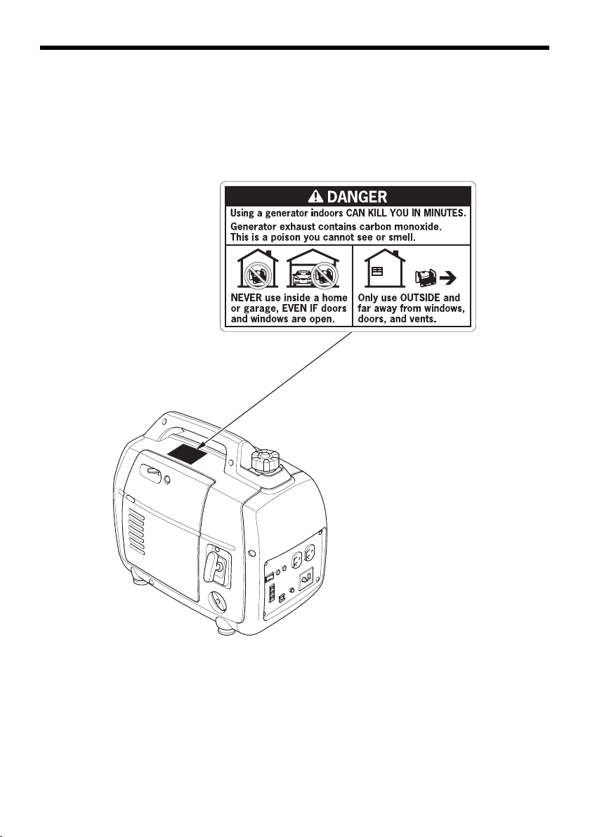
SAFETY LABEL LOCATIONS
These labels warn you of potential hazards that can cause serious
injury. Read them carefully. If a label comes off or becomes hard to
read, contact your Honda servicing dealer for a replacement.
[Example: A type]
9
GENERATOR SAFETY
[Example: A type]
10
CONTROLS & FEATURES
SPARK PLUG MAINTENANCE COVER
MUFFLER
SPARK PLUG
FRAME SERIAL NUMBER
AIR CLEANER
FUEL FILLER CAP VENT LEVER
FUEL FILLER CAP
ENGINE SWITCH
STARTER GRIP
MAINTENANCE COVER
CHOKE LEVER
COMPONENT & CONTROL LOCATIONS
Use the illustrations on these pages to locate and identify the most
frequently used controls.
11
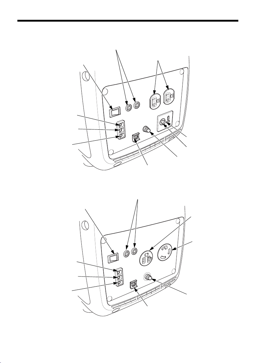
CONTROLS & FEATURES
ECO THROTTLE SWITCH
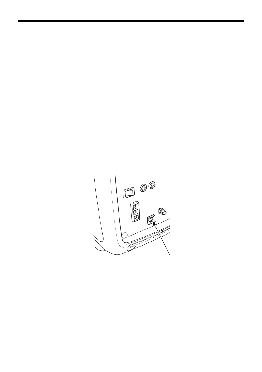
PARALLEL OPERATION OUTLETS
AC RECEPTACLES
DC RECEPTACLE
DC CIRCUIT PROTECTOR
GROUND TERMINAL
OUTPUT INDICATOR
OVERLOAD INDICATOR
OIL ALERT INDICATOR
AC CIRCUIT PROTECTOR
ECO THROTTLE SWITCH
PARALLEL OPERATION OUTLETS
AC CIRCUIT PROTECTOR
GROUND TERMINAL
OUTPUT INDICATOR
OVERLOAD INDICATOR
OIL ALERT INDICATOR
20 A RECEPTACLE
30 A twist lock
receptacle*
[A, A2 types]
[A1 type]
*To obtain more than 1.8 kVA from the 30 A twist lock receptacle, you
must have another EU2200i generator or EU2200i Companion
generator connected in parallel (see page 33).
12
CONTROLS
ENGINE SWITCH
ON
OFF
STARTER GRIP
FUEL OFF
Engine Switch
The engine switch controls the
ignition system and the fuel
valve.
OFF – Stops the engine and
closes the fuel valve.
FUEL OFF – Keeps the ignition
system ON, and closes only the
fuel valve. (see page 28)
CONTROLS & FEATURES
ON – Running position; opens the
fuel valve and allows the engine
to be started.
Starter Grip
Pulling the starter grip operates
the recoil starter to start the
engine.
Do not allow the starter grip to
snap back against the generator.
Return it gently to prevent
damage to the starter.
13
CONTROLS & FEATURES
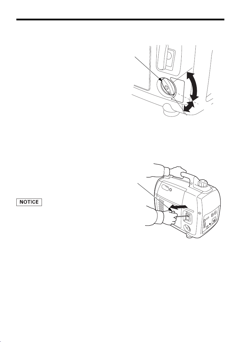
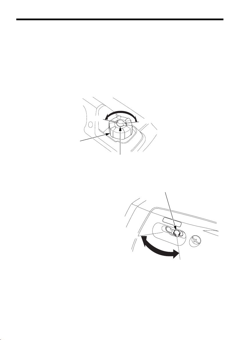
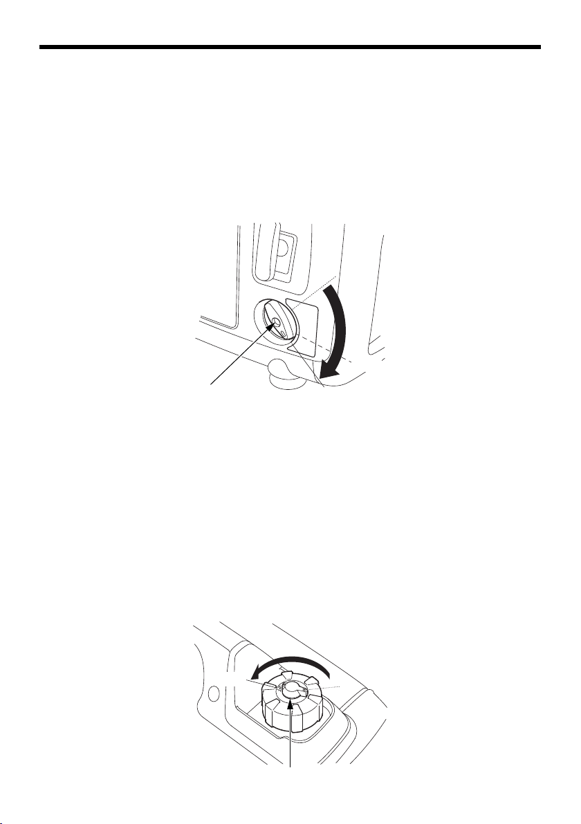
FUEL FILLER CAP VENT LEVER
OFF
ON
FUEL FILLER CAP
OPEN
CHOKE LEVER
CLOSED
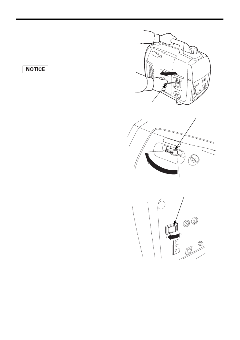
Fuel Filler Cap Vent Lever
The fuel filler cap is provided with a vent lever to seal the fuel tank.
The vent lever must be in the ON position for the engine to run.
When the engine is not in use, leave the vent lever in the OFF position
to reduce the possibility of fuel leakage. Allow the engine to cool well
before turning the vent lever to the OFF position.
Choke Lever
The choke is used to provide
proper starting mixture when the
engine is cold. It can be opened
and closed by operating the choke
lever manually. Move the choke
lever to the CLOSED position to
enrich the mixture for cold
starting.
14
CONTROLS & FEATURES
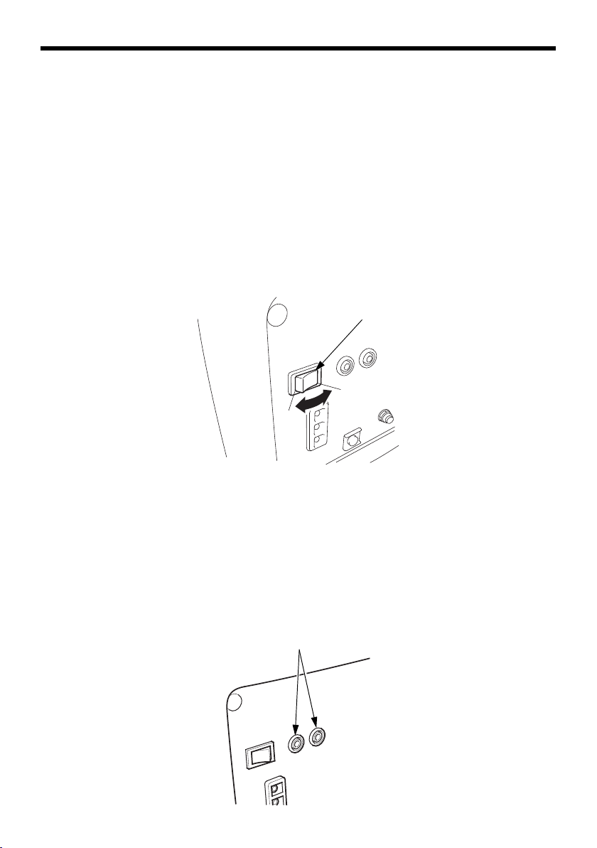
ECO THROTTLE SWITCH
OFF
ON
PARALLEL OPERATION OUTLETS
Eco Throttle® Switch
The Eco Throttle® system automatically reduces engine speed when loads are
turned off or disconnected. When appliances are turned on or reconnected,
the engine returns to the proper speed to power the electrical load.
If high electrical loads are connected simultaneously, turn the
Eco Throttle switch to the OFF position to reduce voltage changes.
When using the DC output, turn the Eco Throttle switch to the OFF
position.
ON: Recommended to minimize fuel consumption and further reduce
noise levels when less than a full load is applied to the generator.
OFF: The Eco Throttle system does not operate.
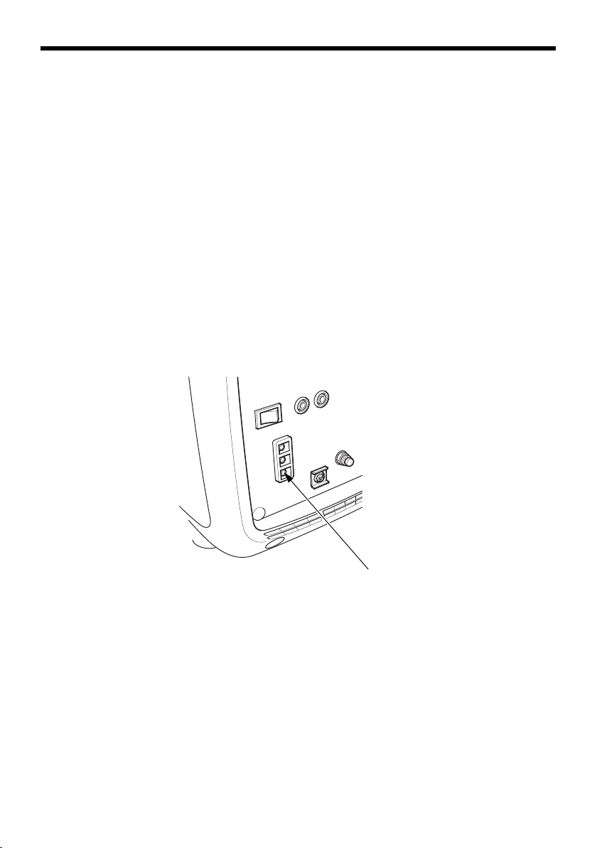
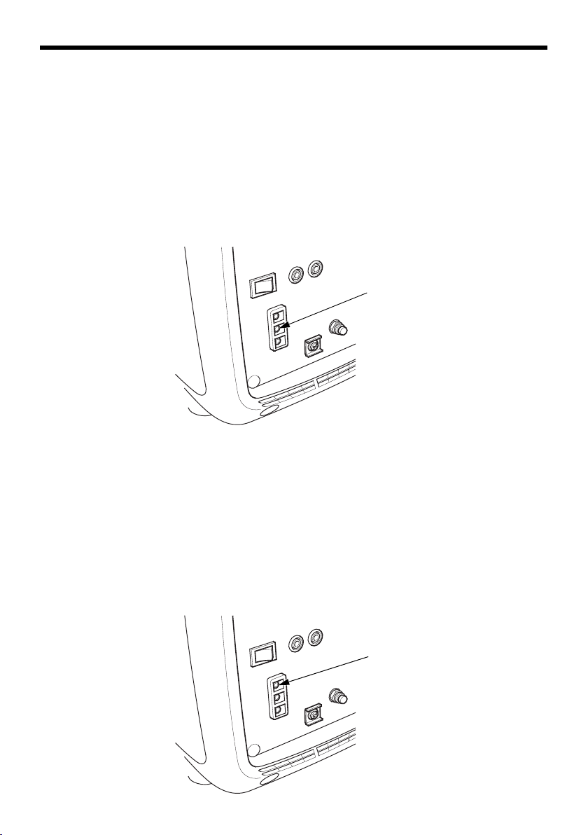
Parallel Operation Outlets
These outlets are used for connecting both types of the EU2200i
generators (Standard and Companion) or EU2000i generators
(Standard and Companion) for parallel operation (see page 33
through 37). A Honda approved parallel operation cable kit (optional
equipment) is required for parallel operation. This kit can be
purchased from an authorized Honda generator dealer.
15
CONTROLS & FEATURES
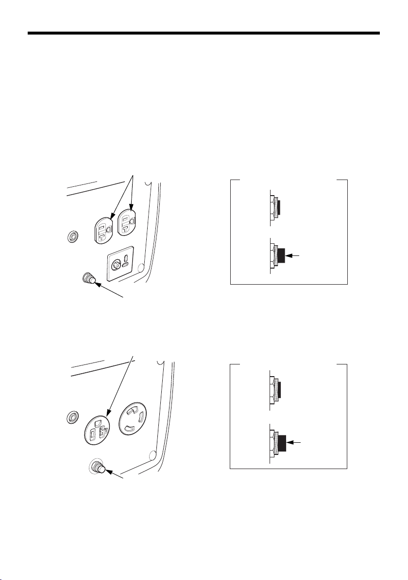
20 A RECEPTACLES
ON
OFF
PUSH
AC CIRCUIT PROTECTOR
AC CIRCUIT PROTECTOR
20 A RECEPTACLE
ON
OFF
PUSH
AC CIRCUIT PROTECTOR
AC CIRCUIT PROTECTOR
AC Circuit Protector
The AC circuit protector will automatically switch OFF if there is a
short circuit or a significant overload of the generator at the 20 A
receptacles. If the circuit protector switches OFF automatically, check
that the appliance is working properly and does not exceed the rated
load capacity of the circuit before resetting the circuit protector ON.
[A, A2 types]
[A1 type]
16
CONTROLS & FEATURES
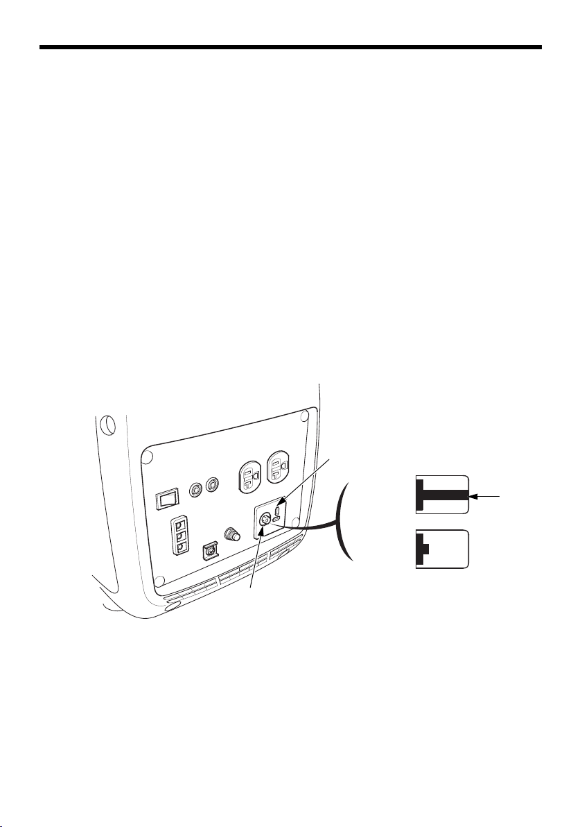
DC RECEPTACLE
OFF
ON
PUSH
DC CIRCUIT PROTECTOR
DC Receptacle [A, A2 types]
The DC receptacle should ONLY be used for charging 12-volt
automotive type batteries. The DC charging output is not regulated.
This means that the charging output does not decrease as the battery
reaches full charge.
Check the battery voltage frequently while charging to prevent
overcharging the battery.
DC Circuit Protector [A, A2 types]
The DC circuit protector automatically shuts off the DC battery
charging circuit when the DC charging circuit is overloaded, when
there is a problem with the battery, or when the connections between
the battery and the generator are improper. However, the DC circuit
protector does not prevent overcharging.
17
CONTROLS & FEATURES
GROUND TERMINAL
FEATURES
Ground Terminal
The generator ground terminal is connected to the frame of the
generator, the metal non-current-carrying parts of the generator, and
the ground terminals of each receptacle.
Before using the ground terminal, consult a qualified electrician,
electrical inspector, or local agency having jurisdiction for local codes
or ordinances that apply to the intended use of the generator.
NEUTRAL FLOATING:
• The generator (stator winding) is isolated from the frame and from
the AC receptacle ground pin.
• Electrical devices that require a grounded receptacle pin connection
will not function if the receptacle ground pin is not functional.
18
CONTROLS & FEATURES
OUTPUT INDICATOR
(GREEN)
Output Indicator
The output indicator (green) is illuminated when the generator is
operating normally. It indicates that the generator is producing
electrical power at the receptacles.
In addition, the output indicator has a simplified hour meter function.
When you start the engine, the indicator blinks according to the
generator’s cumulative operating hours as follows:
• No blinks: 0–100 hours
• 1 blink: 100–200 hours
• 2 blinks: 200–300 hours
• 3 blinks: 300–400 hours
• 4 blinks: 400–500 hours
• 5 blinks: 500 or more hours
19
CONTROLS & FEATURES
OVERLOAD INDICATOR
(RED)
OIL ALERT INDICATOR
(RED)
Overload Alarm (Indicator)
If the generator is overloaded (in excess of 2.2 kVA), or if there is a short
circuit in a connected appliance, the overload indicator (red) will come
ON. The overload indicator (red) will stay ON, and after about four
seconds, current to the connected appliance(s) will shut off, and the
output indicator (green) will go OFF. However, the engine will continue
to run.
If the overload indicator blink continuously,it suggests an abnormal of
inverter unit (see page 68).
Oil Alert
The Oil Alert
®
Indicator
®
system is designed to prevent engine damage caused
by an insufficient amount of oil in the crankcase. Before the oil level in
the crankcase can fall below a safe limit, the Oil Alert indicator (red)
comes ON and the Oil Alert system automatically will stop the engine
(the engine switch will remain in the ON position).
If the engine stops or the Oil Alert indicator (red) comes ON when you
pull the starter grip, check the engine oil level (see page 49) before
troubleshooting in other areas.
20
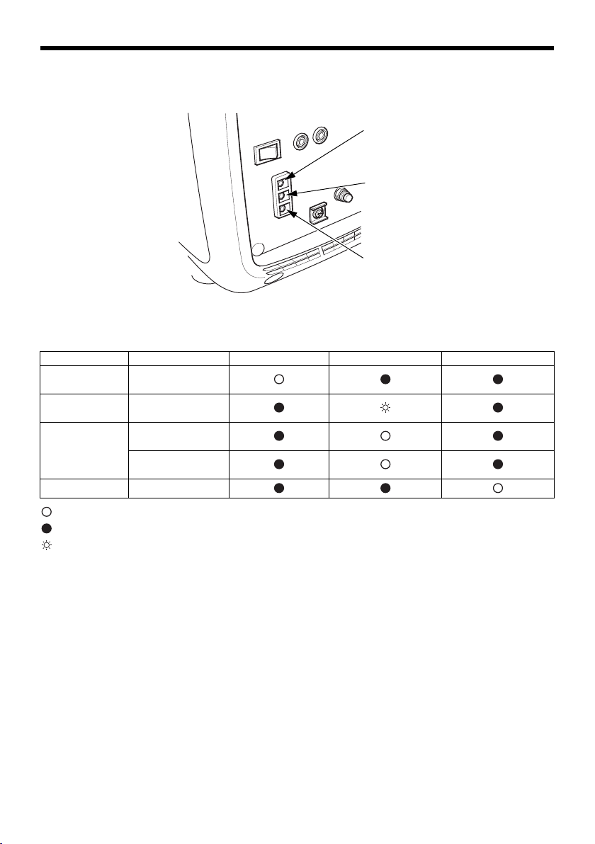
CONTROLS & FEATURES
OIL ALERT INDICATOR
OVERLOAD INDICATOR
OUTPUT INDICATOR
LED Light Patterns
Status Possible cause Output Indicator Overload indicator Oil Alert Indicator
Normal Operating
Malfunction Inverter unit
Abnormal Output
Warning Engine oil low
normally
failure
overcurrent
Inverter unit
overheat
: ON
: OFF
: Blinking
Refer to
TAKING CARE OF UNEXPECTED PROBLEMS
failure diagnosis.
on page 68 for
21
BEFORE OPERATION
ARE YOU READY TO GET STARTED?
Your safety is your responsibility. A little time spent in preparation will
significantly reduce your risk of injury.
Knowledge
Read and understand this manual. Know what the controls do and how
to operate them.
Familiarize yourself with the generator and its operation before you
begin using it. Know how to quickly shut off the generator in case of
an emergency.
If the generator is being used to power appliances, be sure that they do
not exceed the generator’s load rating (see pages 32 and 37).
IS YOUR GENERATOR READY TO GO?
For your safety, to ensure compliance with environmental regulations,
and to maximize the service life of your equipment, it is very important
to take a few moments before you operate the generator to check its
condition. Be sure to take care of any problem you find, or have your
servicing dealer correct it, before you operate the generator.
22
Failure to properly maintain this
generator, or failing to correct a
problem before operation, could
result in a significant malfunction.
Some malfunctions can cause
serious injuries or death.
Always perform a pre-operation
inspection before each operation
and correct any problems.

BEFORE OPERATION
To prevent a possible fire, keep the generator at least 3 feet (1 meter)
away from building walls and other equipment during operation. Do
not place flammable objects close to the engine.
Before beginning your pre-operation checks, be sure the generator is
on a level surface and the engine switch is in the OFF position.
Check the Engine
• Before each use, look around and underneath the engine for signs of
oil or gasoline leaks.
• Check the engine oil level (see page 49). A low engine oil level will
cause the Oil Alert system to shut down the engine.
• Check the air filters (see page 52). Dirty air filters will restrict air flow
to the carburetor, reducing engine and generator performance.
• Check the fuel level (see page 47). Starting with a full tank will help
to eliminate or reduce operating interruptions for refueling.
23
OPERATION
SAFE OPERATING PRECAUTIONS
Before operating the generator for the first time, review chapters
GENERATOR SAFETY
22).
For your safety, do not operate the generator in an enclosed area such
as a garage. Your generator’s exhaust contains poisonous carbon
monoxide gas that can collect rapidly in an enclosed area and cause
illness or death.
(see page 6) and
Exhaust contains poisonous carbon
monoxide gas that can build up to
dangerous levels in closed areas.
Breathing carbon monoxide can
cause unconsciousness or death.
Never run this product's engine in a
closed, or even partly closed area.
BEFORE OPERATION
(see page
Before connecting an AC appliance or power cord to the generator:
• Use grounded 3-prong extension cords, tools, and appliances, or
double-insulated tools and appliances.
• Inspect cords and plugs, and replace if damaged.
• Make sure that the appliance is in good working order. Faulty
appliances or power cords can create a potential for electric shock.
• Make sure the electrical rating of the tool or appliance does not
exceed the rated power of the generator or the receptacle being
used.
• Operate the generator at least 3 feet (1 meter) away from buildings
and other equipment.
• Do not operate the generator in an enclosed structure.
• Do not place flammable objects close to the engine or locate the
generator near flammable materials.
24
OPERATION
FUEL FILLER CAP VENT LEVER
ON
STARTING THE ENGINE
To prevent a possible fire, keep the generator at least 3 feet (1 meter)
away from building walls and other equipment during operation. Do not
place flammable objects close to the engine.
• Operating this generator less than 3 feet (1 meter) from a building or
other obstruction can cause overheating and damage the generator.
• For proper cooling, allow at least 3 feet (1 meter) of empty space
above and around the generator.
Keep all cooling holes open and clear of debris, mud, water, etc.
Cooling holes are located on the side panel, the control panel, and
the bottom of the generator. If the cooling holes are blocked, the
generator may overheat and damage the engine, inverter, or
windings.
Refer to
IS YOUR GENERATOR READY TO GO?
Refer to the
(see page 33) or
the generator.
1. Make sure that all appliances are disconnected from the AC receptacle.
2. Turn the fuel filler cap vent lever to the ON position.
SAFE OPERATING PRECAUTIONS
checks (see page 22).
AC OPERATION
DC OPERATION
(see page 30),
(see page 38) for connecting loads to
on page 24 and perform the
AC PARALLEL OPERATION
25
OPERATION
ECO THROTTLE SWITCH
OFF
CHOKE LEVER
CLOSED
ON
ENGINE SWITCH
3. Make sure the Eco Throttle
switch is in the OFF position, or
more time will be required for
warm-up.
4. To start a cold engine, move
the choke lever to the CLOSED
position. To restart a warm
engine, leave the choke lever in
the OPEN position.
5. Turn the engine switch to the
ON position.
26
6. Pull the starter grip lightly until
STARTER GRIP
CHOKE LEVER
ECO THROTTLE SWITCH
OPEN
Direction to pull
ON
you feel resistance; then pull
briskly in the direction of the
arrow as shown.
Do not allow the starter grip to
snap back against the
generator. Return it gently to
prevent damage to the starter.
7. If the choke lever was moved to
the CLOSED position to start
the engine, gradually move it to
the OPEN position as the
engine warms up.
OPERATION
8. If you wish to use the
Eco Throttle system, turn the
Eco Throttle switch to the ON
position after the engine has
warmed up for 2 or 3 minutes.
27
OPERATION
ENGINE SWITCH
OFF
FUEL OFF
FUEL FILLER CAP VENT LEVER
OFF
STOPPING THE ENGINE
To stop the engine in an emergency, simply turn the engine switch to
the OFF position securely. Under normal conditions, use the following
procedure.
1. Turn off or disconnect all appliances that are connected to the
generator.
2. Turn the engine switch to the OFF position securely.
Operating the generator in the FUEL OFF position before turning the
engine switch to the OFF position can reduce the fuel in the
carburetor.
• When using the FUEL OFF position, the generator will continue to
run for several minutes until the fuel in the carburetor has been
consumed, and then the engine will stop.
• Turn the engine switch to the OFF position after the engine stops.
• After stopping the engine using the FUEL OFF position, restarting
the engine will require additional pulls on the recoil starter.
3. Allow the engine to cool, and then turn the fuel filler cap vent lever
to the OFF position.
28
 Loading...