

Honda CRF50F (2009), CRF50F (2006), CRF50F (2010), CRF50F (2011), CRF50F (2005) Service & Repair Manual
...
1.
GENERAL INFORMATION
SERVICE RULES ............................................ 1-2
MODEL IDENTIFiCATION .............................. 1-2
GENERAL
SPECiFiCATIONS
..
· .......... · ...... · .... 1-5
LUBRICATION SYSTEM SPECIFICATIONS · 1-6
FUEL
SYSTEM SPECiFiCATIONS ........ · ........ 1-6
CYLINDER HEAD/
VALVES SPECIFICATIONS .......................... · 1-6
CYLINDER/PISTON SPECiFiCATIONS
........ · 1-7
CLUTCH/GEARSHIFT
LINKAGE SPECIFICATIONS · .......... · .... ·
..
· ...... 1-7
ALTERNATOR /
CAM
CHAIN TENSIONER
SPECiFiCATIONS
.......... ···
.. ··
.... ·· .... · ...... ·
.. · ..
··· 1-7
CRANKSHAFT/TRANSMISSION/
KICKSTARTER SPECIFICATIONS
.... · ........ · .... 1-8
FRONT WHEEL/BRAKE/SUSPENSION/
STEERING SPECIFICATIONS·
..
·· .... · ......
··
..
· .... 1-8
REAR
WHEEl/BRAKE
/
SUSPENSION SPECIFICATIONS ...... · .... ·
..
· .... 1-8
IGNITION SYSTEM SPECIFICATIONS · ........ ·1-9
TORQUE VALUES
...... · ........ · ........................ 1-10
LUBRICATION
& SEAL POINTS ·
.. · ..
· .... ·
.. · ..
·1-13
CABLE & HARNESS ROUTING ·
..
· ...... ·
.. · .. · ..
1-14
EMISSION CONTROL SYSTEMS ........ · ...... ·1-
17
•
1-1
GENERAL INFORMATION
SERVICE RULES
1.
Use
genuine
Honda
or
Honda-recommended
parts
and
lubricants
or
the
ir
equivalents
. Parts that
don
't
meet
Honda's
design specifications
may
cause
damage
to
the
motorcycle.
2.
Use the special
tools
designed
for
this
product
to
avoid
damage
and incorrect assembly.
3.
Use
only
metric
tools
when servicing the motorcycle.
Metric
bolts, nuts and screws are
nol
interchangeable
with
English fasteners.
4.
Install
new
gaskets, O-rings. cotter pins, and lock plates
when
reassembling.
5.
When
tightening
bolts
or
nuts, begin
with
the
larger
diameter
or inner
bolt
first. Then
tighten
to
the
specified
torque
diagonally in incremental steps unless a particular sequence is specified.
6. Clean parts
in
cleaning solvent
upon
disassembly. Lubricate
any sliding
surfaces before reassembly.
7.
After
reassembly, check all parts
for
proper
installation
and
operation.
8.
Route all electrical
wires
as
shown
on
page 1-14, Cable
and
Harness
Routing
.
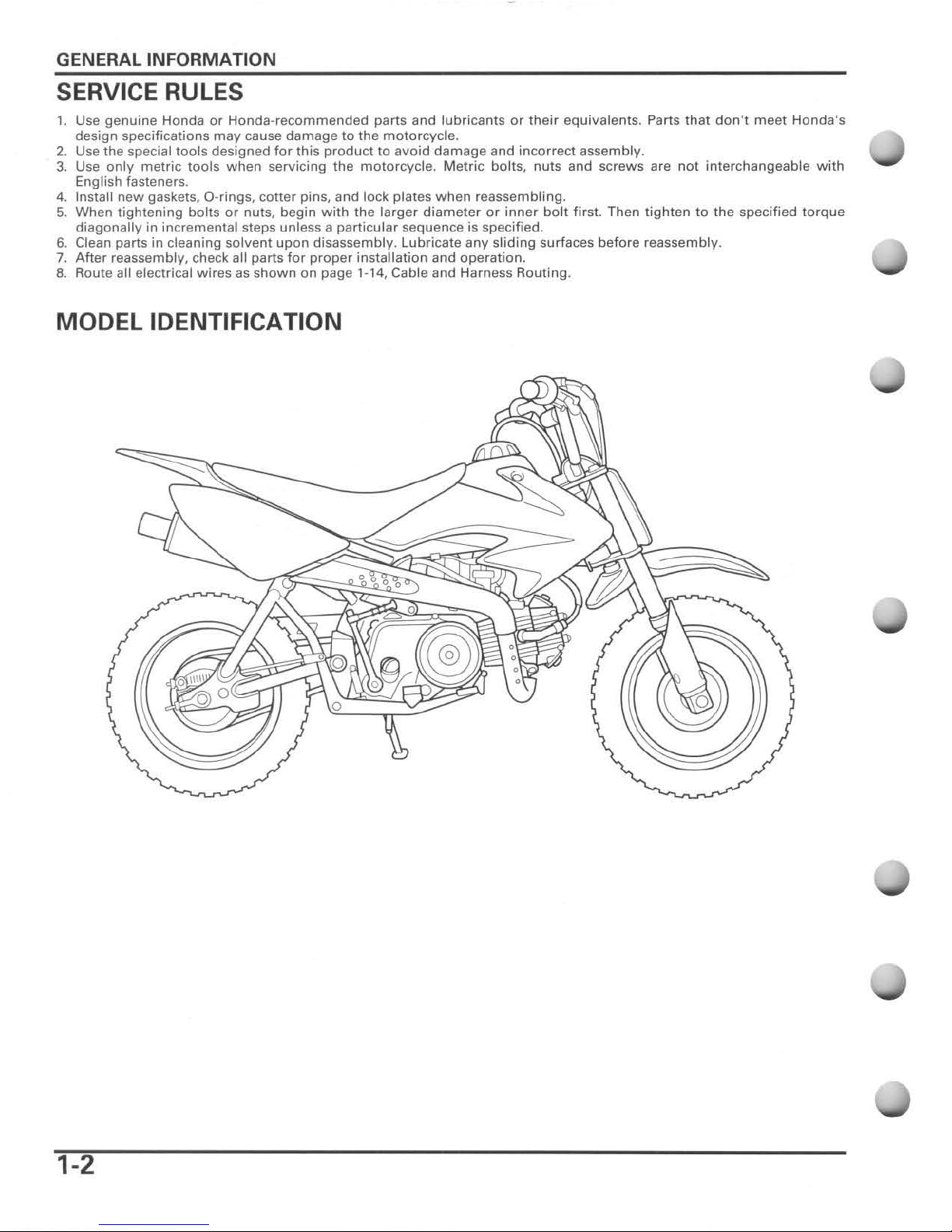
MODEL IDENTIFICATION
1-2
,
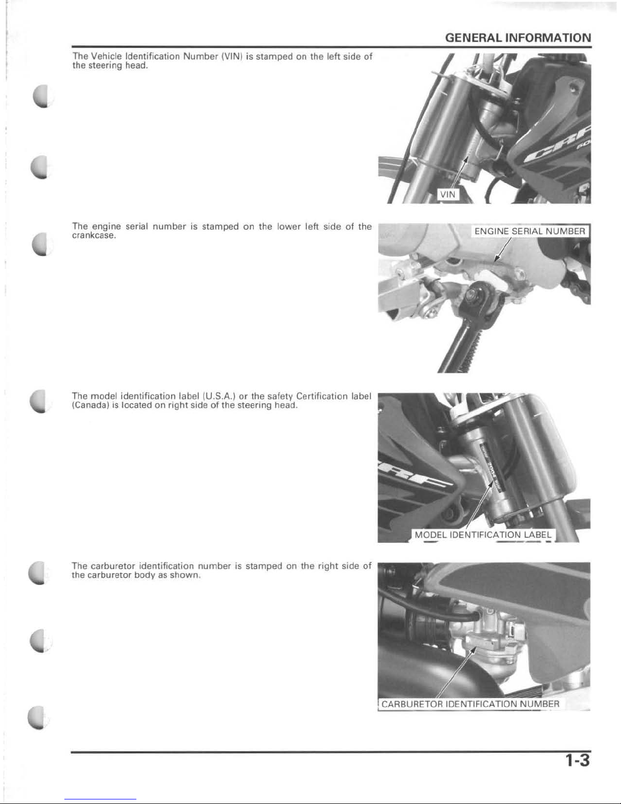
The Vehicle Identification
Number
(VIN) is
stamped
on the
left
side
of
the steering head.
The
engine
serial
number
is stamped
on
the
lower
left
side
of
the
crankcase.
The
model
identification
label (U.S.A.)
or the safety Certification label
(Canada) is located on
right
side
of
the
steering
head.
The
carburetor
identification
number
is
stamped
on
the
right
side
of
the
carburetor
body
as
shown
.
GENERAL
INFORMATION
1-3
GENERAL
INFORMATION
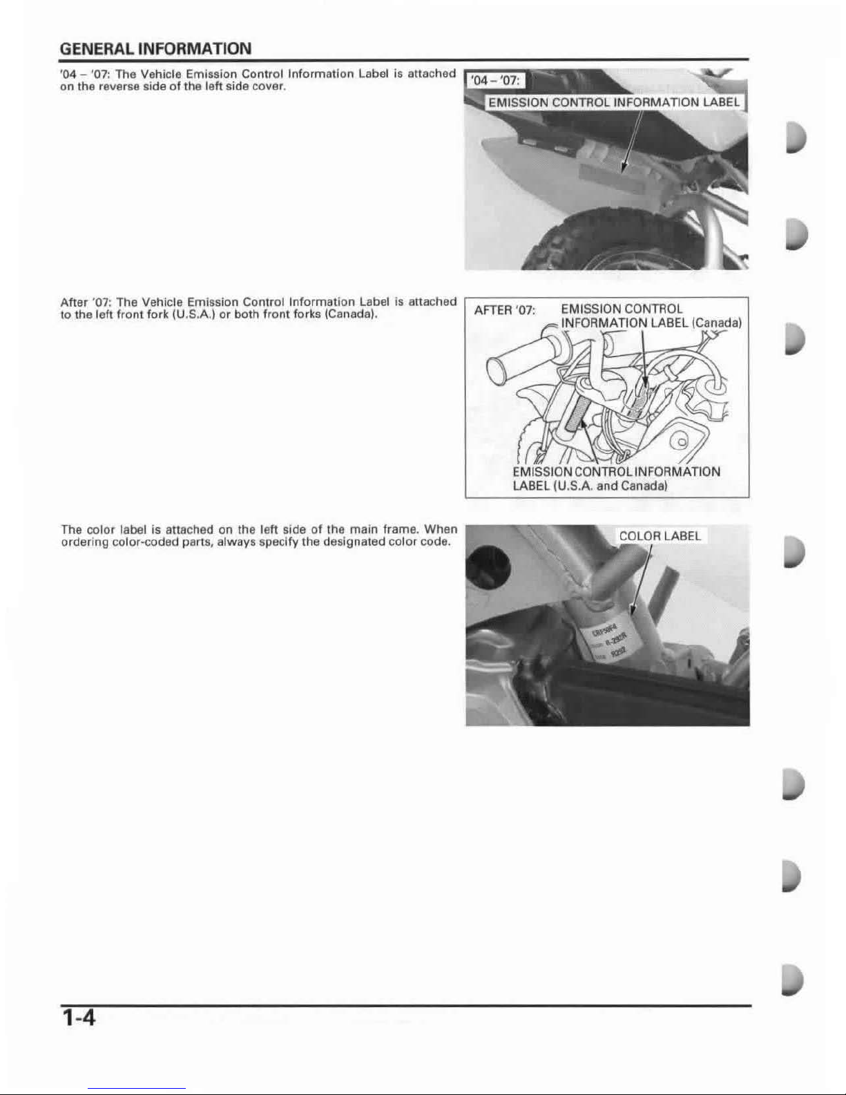
'
04
- '07:
The
Vehicle Emission Conlrol Information
labe
l is attached
on the reverse side of the
left side cover.
After
'07: The Vehicle Emission Control Information label is attach
ad
,----------,-------
- -
to the leh fro
nl
fork (U.S.
A.)
or both front forks (Canada).
AFTER '07
:
EMISSION
CONTROL
INFORMATION LABEL (Canada)
EMISSION
CONTROL
INFORMATION
LABElIU.5A
and Canada)
The
color label
is
allached
on
the left side
of
the main frame. When
P---
....
..,.......,
ordering color.-coded parts, always specify the deslgnaled color code.
1-4
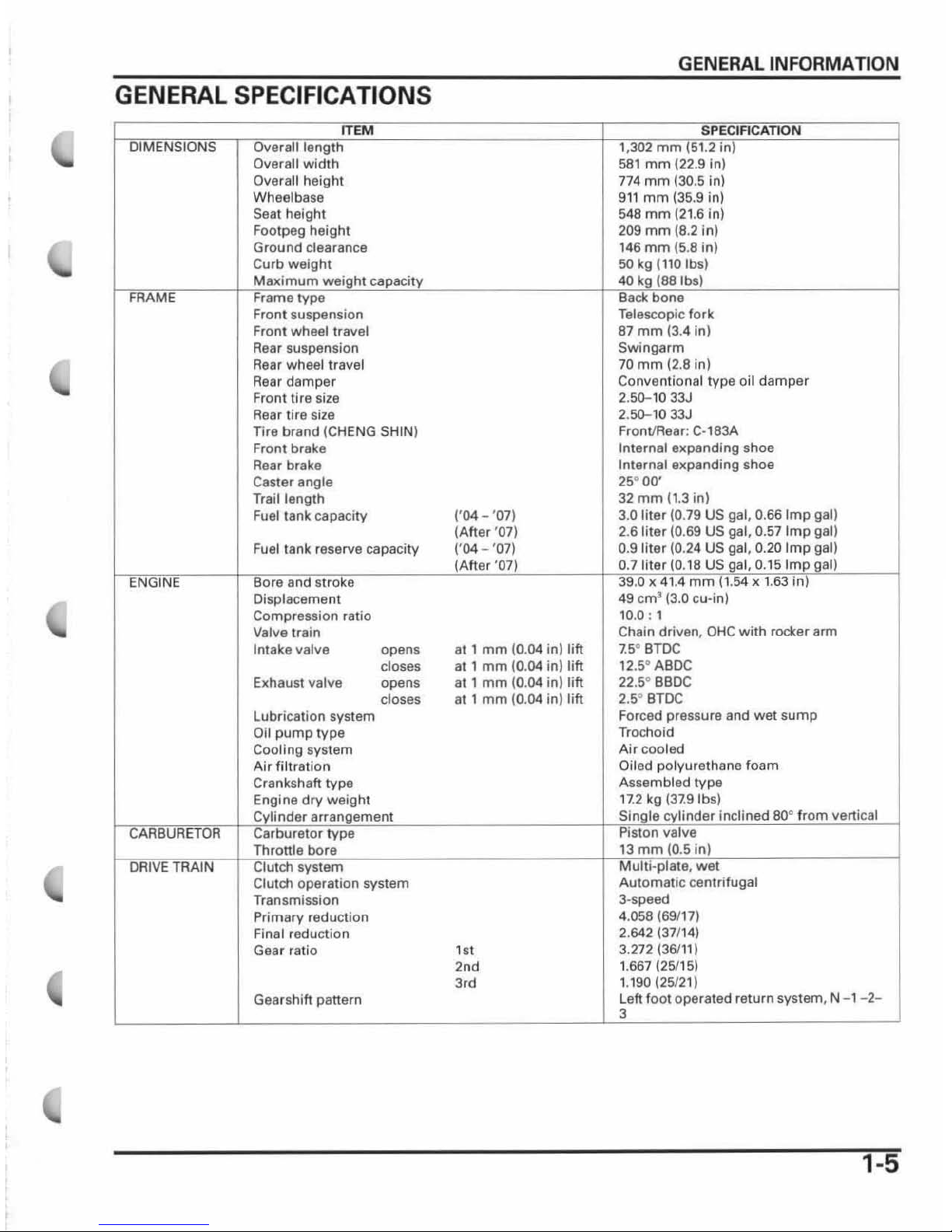
GENERAL
SPECIFICATIONS
I I
Overall width
Overall
height
Wheelbase
Sea
t height
Foolpeg height
Ground
clearance
Curb weight
Front suspension
Front wheel
travel
Rear suspension
Rear wheel travel
Rear
damper
Front tire size
Rear tire size
Tire
brand (CHENG SHIN)
Front brake
Rear
brake
Casler
angle
Trail
length
Fuel lank capacity
Fuel
tank reserve capacity
Displacement
Compression ratio
Valve
train
Intake valve opens
closes
Exhaust valve opens
Lubrication
system
Oil
pump
type
Cooling system
Air filtration
Crankshaft
type
dry weight
system
doses
Clutch operation system
Transmission
Primary reduction
Final reduction
Gear ratio
Gearshift panern
('
04-
'07)
(After
'07)
('04
- '07)
al 1
mm
(0.04 in) tift
at 1
mm
(0.04 in)
lift
at , mm
(0.04 iollift
at 1
mm
(0.04
in)
Jift
,,,
2nd
3,d
GENERAL
INFORMATION
mm
581 mm
(22.9 in)
774
mm
(30.5 in)
911
mm
(35.9 in)
548
mm
(21.6 in)
209
mm
(8.2 in)
146
mm
(5.8
in)
50
kg
(110
Ibs)
Telescopic
fork
87
mm
(3.4 in)
Swingarm
70
mm
(2.8 in)
Conventional type
oil
damper
2.50-1033J
2.
50-1033J
Front/Rear: C·183A
Internal
expanding shoe
Internal expanding shoe
25° 00'
32
mm
(1.3
in)
3.0
liter
(0.79 US gal, 0.66
Imp
gal)
2.61i1er (0.69
US gal, 0.57
Imp
gal)
0.9
liter
(0.
24
US gal, 0.20
Imp
gal)
0.7
.
t8US
0.15 I
49 cm' (3.0 cu·in)
10
.0 : 1
Chain driven ,
OHC
with roctet
arm
7.5
0
BTDC
12
.5°
ABDC
22
.5°
BBDC
2
,so
BTDC
Forced pressure and
wet
sump
Trochoid
Air
cooled
Oiled polyurethane foam
Assembled
type
, 7.2 kg
(37.9
Ibs)
inclined 80°
Automatic
centrifugal
3·speed
4.
058
(69117)
2.642137/
'4)
3.272136111)
1.667
(25115)
1.190
(25121)
Left
foot
operated return system, N - 1- 2-
1-5
GENERAL INFORMATION
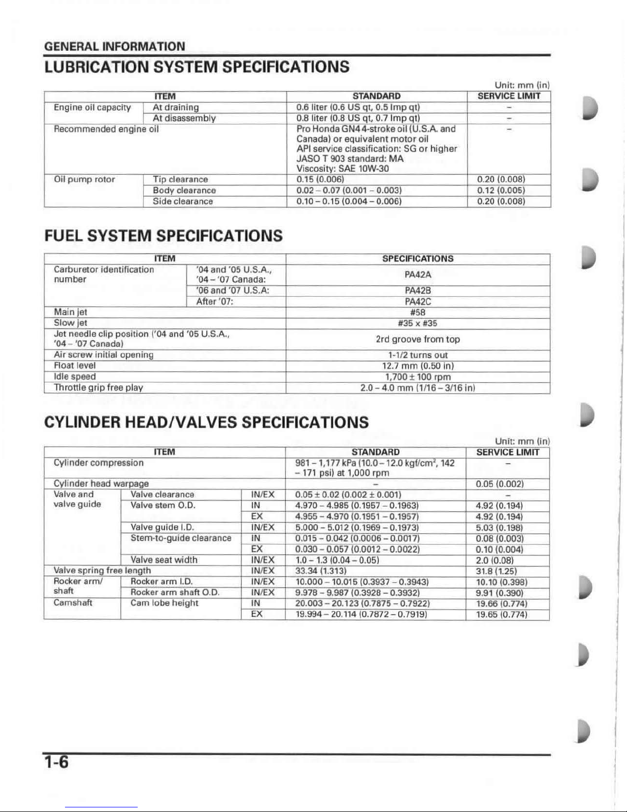
LUBRICATION SYSTEM SPECIFICATIONS
Canada)
or
equivalent mOler oil
API
service classification:
SG
or higher
JASOT .
MA
FUEL SYSTEM SPECIFICATIONS
number
PA42A
2rd groove from top
CYLINDER
HEADIVALVES
SPECIFICATIONS
valve guide
I
I
1-6
I
I
 Loading...