

Page 1
PRICE .35
Mf r' s N o. 1 7 3~ ]
P. T. O . Dr iv en Vac u u m Co ll e ct o r
fo r T -1 0, T -1 2 ,T - 15 & T- 1 6 T r ac to r s
No. L M- 16 0 01 - 73
Assembly Instructions and Parts List
High Cap aci ty Tra ile r F ram e a nd Cov er No.L M- 099 05- 31
Low P rofi le Tr ail er Fra me and Co ver No. L M- 099 06 -24
Rovi ng Nozz le No. L M- 099 04-4 7
PART NO. 24769
Page 2

Safety
□ □ □
□ Know the controls and how to stop quickly-READ THE
OWNER'S MANUAL.
□ Do not allow children to operate vehicle. Do not allow-
adults to operate it without proper instruction.
□ Do not carry passengers. Keep children and pets a safe
distance away.
□ Clear work area of objects which might be picked up and
thrown,
□ Disengage all attachment clutches and shift into neutral
before attempting to start engine (motor}.
□ Disengage power to attachments and stop engine (motor}
before leaving operator position.
□ Disengage power to attachment(s) and stop engine
{motor} before making any repairs or adjustments.
□ Disengage power to attachments when transporting or
not in use.
□ Take all possible precautions when leaving vehicle un
attended; such as disengaging power-take-off, lowering
attachments, shifting into neutral, setting parking brake,
stopping engine and removing key.
□ Do not stop or start suddenly when going uphill or down
hill. Mow up and down the face of steep slopes; never
across the face,
□ Reduce speed on slopes and in sharp turns to prevent
tipping or loss of control. Exercise extreme caution when
changing direction on slopes,
□ Stay alert for holes in terrain and other hidden hazards.
О Use care when pulling loads or using heavy equipment.
A, Use only approved drawbar hitch points.
B, Limit loads to those you can safety control.
C, Do not turn sharply. Use care when backing.
D, Use counterweight(s) or wheel weights when
suggested in Owner's manual,
□ Watch out for traffic when crossing or near roadways.
□ When using any attachments never direct discharge of
material toward bystanders nor allow anyone near vehicle
while in operation.
□ Handle gasoline with care — it is highly flammable.
A. Use approved gasoline container.
B. Never remove cap or add gasoline to a run
ning or hot engine or fill fuel, tank indoors.
Wipe up spilled gasoline.
C. Open doors if engine is run in garage — ex
haust fumes are dangereous. Do not run
engine (motor) indoors,
□ Keep vehicle and attachments in good operating condi
tion and keep safety devices in place.
□ Keep all nuts, bolts, and screws tight to be sure equip
ment is in safe working condition.
□ Never store equipment with gasoline in the tank inside a
building where fumes may reach an open flame or spark.
□ Allow engine to cool before storing in any enclosure.
□ To reduce fire hazard keep engine free of grass, leaves or
excessive grease.
□ Vehicleand attachment should be stopped and inspected
for damage after striking a foreign object and the damage
should be repaired before restarting and operating the
equipment.
□ Do not change engine governor settings or overspeed
engine.
□ When using vehicle with mower:
(1) Mow only in daylight or in good artificial
light.
(2) Never make a cutting height adjustment
while engine (motor) is running if operator
must dismount to do so.
(3) Shut engine (motor) off when removing grass
catcher and/or unclogging chute.
(4) Check blade mounting bolts for proper tight
ness at frequent intervals.
□ Check grass catcher bags frequently for wear or deteri
oration. Replace with new bags for safety protection.
WARRANTY
We warrant this HOMELITE product to be free from defects in material or workmanship under normal use and
service, except that we make no warranty, express or implied, with respect to tires, engines, generators or voltage
regulators (which usually are warranted by their respective manufacturers) nor with respect to any unit which
after sate by HOMELITE has been altered in any way without HOME LITE'S express consent.Our obligation under
this warranty is limited to replacing, without charge any part which is proven defective within one year (30 days
if the unit is used for commercial, rental or municipal purposes) from date of purchase, if returned to us, with
transportation charges prepaid, at a HOMELITE branch office or to a dealer whom we have authorized to' make
the replacement.
THIS WARRANTY IS IN LIEU OF ALL OTHER WARRANTIES, EXPRESS OR IMPLIED, OF MERCHANT
ABILITY, FITNESS FOR A PARTICULAR PURPOSE, PERFORMANCE OR OTHERWISE AND IN NO EVENT
SHALL HOMELITE BE LIABLE FOR ANY INCIDENTAL, SPECIAL OR CONSEQUENTIAL DAMAGES.
HOMELITE
a (iiyision of T«itran 1лс.
Page 3
HOMELITE PT.O. Driven Vacuum Collector
TheHOMELITE PTO Driven Vacuum Collector requires two
accessories for its operation. These are a) a HOMELITE
dump cart and b) either one of two available cart covers .
Not required, but available as an option, is a roving nozzle
for the vacuum collector. The assembly instructions and
parts lists for the PTO Driven Vacuum Collector, the two
cart covers and the roving nozzle are contained in this book,
The instructions and parts list for the dump cart will be
found packaged with the car .
Assembly
Mounting the Vacuum Collector
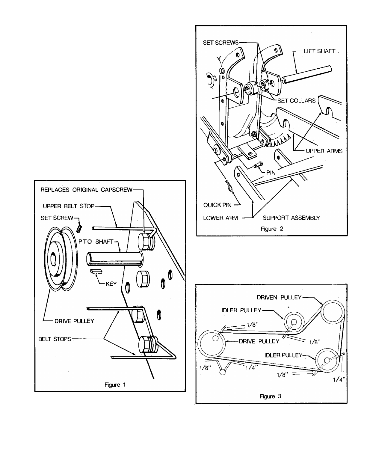
1. Install the drive pulley on the tractor PTO shaft using
a 3/16 X 3/16 X 1" key. Secure the pulley with the set
screw provided. Install the three belt stops on the
tractor frame. The 7/16-14 x 1-1/4" capscrew pro
vided for the upper belt stop, replaces the original cap
screw on the tractor (Figure 1).
2. Install the lift shaft on the rear of the tractor usingthe
two set collars. Secure the set collars with the two
5/16-18 set screws provided (Figure 2).
3. Place the hooks on the upper arms of the support as
sembly over the lift shaft. Align the holes in the lower
arm of thesupportassembly with the holes in the tractor
frame. Secure with two pins and two quick pins.
(Figure 2)
4. Move the PTO lever forward to the disengaged position.
Install thedrive belt over the drive pulley. Align the
drive pulley with the pulleys in the belt drive cover.
Check to insure that the belt is properly seated in the
four pulleys. Adjust the belt stops as shown (Figure 3).
5. Attach the deflector to the blower housing with two 3/8"
self tapping screws (Figure 4).
6. Place the 6" diameter hose over the deflector and blower
housing and secure with the smaller of the hose clamps
using one 1/4-20 X 2" machine screw, lockwasher and
hex nut (Fieure 41.
Page 4
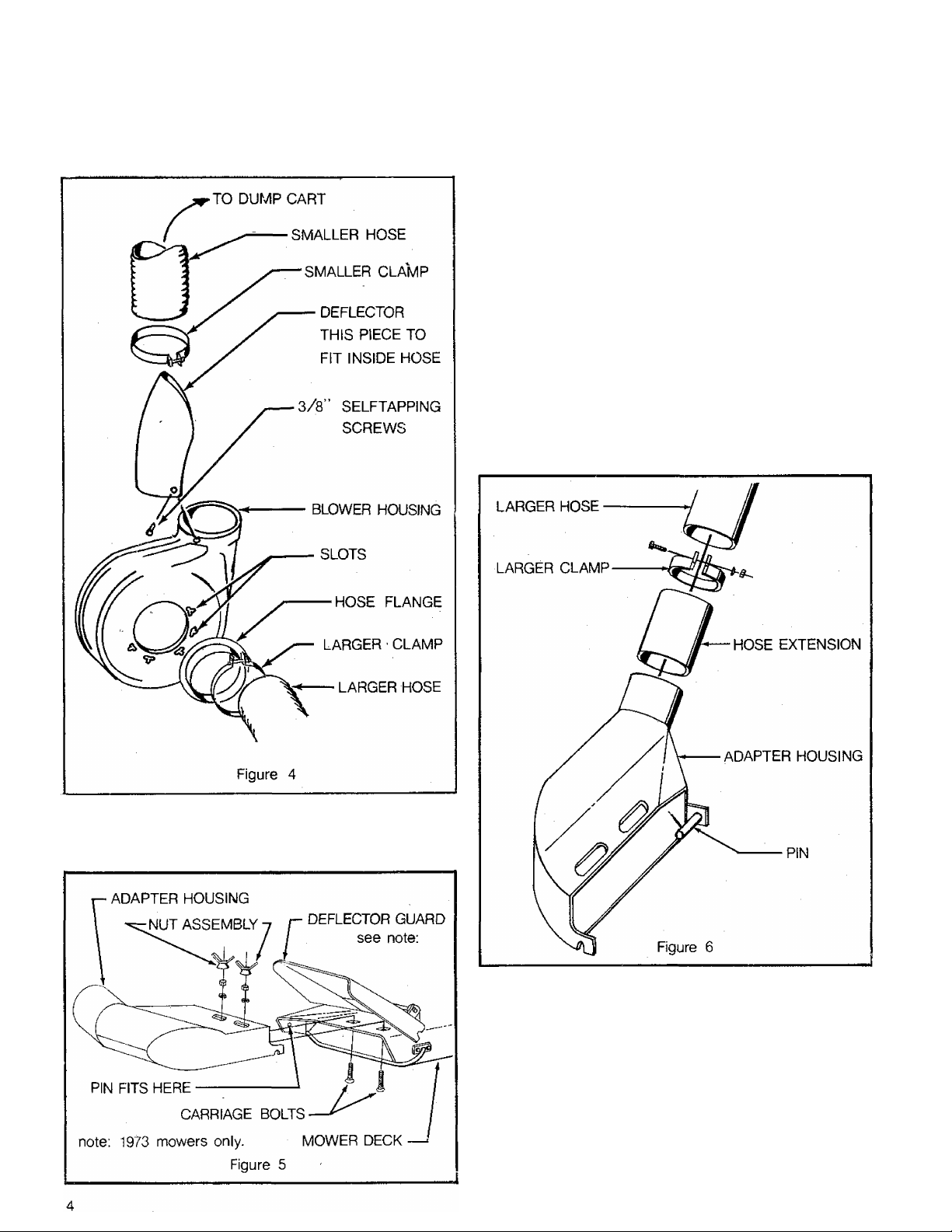
7. Mount one end of the 7” hose to the hose flange using
one of the larger hose clamps and one 1/4-20 x 2” ma
chine screw, lockwasher and hex nut (Figure 4).
8. Slide the hose flange into the slots in the blower hous
ing (Figure 4).
NOTE: 1973 mowers 42” and 48" are equipped with a de
flector shield. To mount the adapter on these
mowers, raise the mower to full height and remove
the two carriage bolts holding the deflector in the
position. Lift the deflector to a vertical position
and install the adapter following assembly instruc
tions No. 10 and No. 11. After this is done, fold the
deflector shield down so that it rests on top of the
adapter housing (Figure 6).
10. Raise the mower to full height. Install the two 3/8-16
X 1" carriage bolts through the holes in the mower deck
from underneath. Secure with two 3/8” lock washers
and two 3/8-16 hex nuts (Figure 6).
11. Insert the pin on the rear edge of the vacuum collector
adapter through the hole in the rear edge of the mower
deck. Locate the two large holes in the top of the adapter
over the carriage bolts in the mower deck. Secure with
the two nut assemblies (Figure 6).
12. Slide thehose extension over theadapter discharge pipe
(Figure 5).
o
9. Install the hose extension in the other end of the 7" hose.
Secure with the other large hose clamp and one 1/4-20
X 2" machine screw, lockwasher and hex nut (Figure 5).
Mounting the High Capacity and Low Profile Trailer
Frames and Covers
There are two covers available for the HOMELITE dump
cart for use with the HOMELITE vacuum collector system.
These are the low profile trailer frame and cover and the
high capacity trailer frame and cover. Both covers come
preassembled to their frames.
The low profile trailer frame and cover is assembled as
follows:
IJ/
Page 5

if^
with the hose sleeve). The special studs are inserted
from the inside (Figure 7).
2. Lay the assembly on the cart with the canvas side flaps
inside the cart.) Engage the front stops over the box
front edge, then pull the rear latch down and hook it under
the box rear edge (Figure 8).
the dump cart as follows:
1. Remove the tailgate from the dumpcart.
3. Place the 6" diameter hose in the cover sleeve and se
cure by tightening the strap in the sleeve.
Page 6

2. Install^the front catch using a 3/i-16 x 1” capscrew,
flatwasher and locknut. Tighten the locknut so that it
will hold, securely but still allow the catch to pivot.
(Figure 9).
3. Unfold the canvas and frame assembly so that the front
and rear uprights are in a vertical position. Align the
side "Z" bars with the cart side wall upper edges and
slide the assembly forward onto the cart (Figure 10). Be
sure that the front of the cover frame is toward the front
of the cart. Turn the front catch down over the front
edge of die cart.
7. Place the 6” diameter hose in the cover sleeve and tighten
the strap in the sleeve (Figure 9).
8. Secure one end of the spring to the strap in the cover
sleeve by knotting the end of the strap to the spring. In
sert the other end of the spring through the hole in the
end of the hook. Then place the hook over the lip on the
front of the dump cart body (Figure 9).
Mounting the Roving Nozzle
The roving nozzle attaches to the blower inlet in place of the
hose from the mower. For storage a rack is provided for
installation on the front of the dump cart (Figure 12.)
4. Secure the four crossbrace tubes with the hardware at
tached (Figure 9).,
1. Install the hose flange and a hose clamp on the plain end
of the hose. Secure with one 1/4-20 x 3” machine screw,
lockwasher and hex nut (Figure 4),
2. Install the hose handle clamps the desired distance from
the pickup end of the hose and attach the handle.
(Figure 13),
6. Engage the upper doorframe side capscrews in the upper
hanger brackets and push the bottom edge into place in
the box bed. Engage the rear latches to the lower door
frame side capscrews (Figure 11).
Page 7

:)
3. Attach the flanged end of the roving nozzle to the blower
housing, seating the flange fully in the slots (Figure 4),
4. The storage rack is assembled and hung on the front of
the cart. No hardware for mounting is required.
(Figure 14).
5. Periodically check the hoses and blower housing to in,sure grass clippings have not accumulated which will
affect the flow of grass to the dump cart.
6. Unzip the zipper on the canvas cover during normal op
eration to provide an air release in the cart enclosure.
During some operations it may be desirable to have the
zipper in the half closed or fully closed position.
1. Check to insure that the hoses are securely fastened to
the blower housing, mower adapter and trailer cover
sleeve.
2. Ground speed and throttle adjustment for the vacuum
collector will vary according to the type of work being
done. When making a shallow cut of fairly dry grass, a
faster ground speed (third or fourth gear on manual trans
mission tractors) and lower throttle setting can be used When collecting wet, thick or heavy material, use a
slower ground speed (first or second gear on manual
transmission tractors) and run the engine at near full or
full throttle. This will produce increased vacuum.
7. After using,
cart.
Caution;
clean out grass in neck of hose and dump
Before disconnecting any hoses or perform-,
ing any maintenance or adjustment work, be
sure that the tractor engine is off and the
tractor parking brake is engaged. Do not op
erate unit if either one or both hoses are not
connected to the blower assembly.
Trouble Shooting
If leaves and grass are not being picked up, check the
following:
1. Run the engine at full throttle and use a slow ground
speed (first gear or manual transmission tractors).
2. Check all hose connections to be sure they are tight.
3. Check hoses and blower housing to be sure they have not
become plugged with grass or leaves.
If the hoses become plugged, check the following:
1. Grass may be too high or wet, use only half the mower
width.
2. Use a slow ground speed and run the engine at full throttle
(first gear on manual transmission tractors).
3. Raise the mower to full height for the first pass, lower
it to make a second pass.
After each use
A
3. When picking up leaves and tall grass, raise the mower
to the highest cutting position. A second pass can then
be made with the mower at a lower setting to complete
the job.
4. hi wet and extremely high grass, it may be necessary to
pick up only half of the mower width to prevent the hoses
from becoming clogged with grass.
HOMEUTE*
PORT CHESTER, NEW YORK, U.S.A. 10573
Be sure to clean out the hoses and cart thoroughly, espe
cially at the cover sleeve connection.
Storage
Remove the door on the high capacity cart cover or the en
tire low profile cover and place it where air will circulate
around it. This will prevent rotting of the fabric.
1 tflirtroni
DIVISION
Page 8

I j)
Page 9

P. T. O . Dr i ve n V a cu u m C ol l ec t or
No. Description Part No. Qty. No.
1
"V" EELT-drive
COVER-beit drive LM-16056-59
2
SCREW-cap, 5/16-18 x 2
3
SCREW-cap, 5/16-18 x 4
4
SCREW-cap, 7/16-14 x 1-1/4
5
SCREW-set, 5/16-lS'x 1/2 sq.hd. cup.pt. LM-09287-21
6
KEY-parallel, fiat, 3/16 x 3/16 x 1 LM-09058-50
7
PULLEY LM-01642-02
8
WASHER-flat, 7/16 LM-09184-30
9
SCREW-cap, 3/8-16 x 1-1/8
10
WASHER-flat, 13/32 x 7/8 LM-09249-40 7
11
STOP-belt
12
WASHER-lock, 3/8 LM-09169-65
13
NUT-hex, 3/8-16
14
WASHER-lock, 1/4 LM-09169-64 13
15
NUT-hex, 1/4-20
16
NUT ASSEMBLY
17
BOLT-carriage LM-07030-07
18
19 ADAPTER-vacuum collector
EXTENSION-hose LM-01231-17
20
SHAFT-lift LM-16076-87
21
COLLAR-set LM-16075-53
22
23 COLLAR-set
SCREW-set, 5/16-18 x 3/8 LM-09287-09 2
24
25 PIN-quick
SUPPORT ASSEMBLY-blower housing
26
27 PIN
SCREW-set, 1/4-20 x 5/16 LM-O9O3 8 7 O7
28
COLLAR-set LM-81910-22
29
30 S PRIN G- compr es s ion
31 GUIDE ASSEMBLY-rod
ROD-control LM-160 9 8-11
32
PIN" quick
33
WASHER-flat, 11/32 x 7/8
34
SCREW-cap, 3/8-16 x 1-1/2
35
36 CLAMP-hose
37 WASHER-flat, 13/32 x 1-1/2
SCREW-machine, 1/4-20 x 2
38
SPACER-pivot LM-16062-33
39
NUT-hex, 5/16-18
40
WASHER-lock, 5/16
41
WASHER-lock, 7/16 LM-09181-99
42
SCREW-cap, 5/16-18 x 3/4
43
44 LEVER-PTO
NUT-hex lock, 5/16-18
45
PIN-cotter, 3/32 X 3/4
46
LM-01650-4S 1
LM-09193-55
LM-09221-04
LM-09234-71 1
LM-09193-58
LM-16 06 0-14 3
LM-09169-50 11
LM-09166-22 13
LM-01230-60 2 63 GUIDE ASSEMBLY-rod
LM-16056-87
LM-80210-10
LM-81610-45 2 ■
LM-16074-53
LM-01550-37 2
LM-16024-05 1 76
LM-01584-06
LM-01067-87 5 79 NUT-hex lock, 3/8-16
LM-092 84-74 4
LM-09193-61 3
LM-01230-65 2
LM-09243-56 2
LM-09174-56 3
LM-09173-72 5
LM-09173-56 5
LM-09173-97 2
LM-16058-10
LM-09233-62 2
LM-09184-47
1
1
1 00
2
1
1
1
1
14 59
2
1
1 66 SCREW-set, 5/16-18 x 5/16 cup pt.
1
1
1
1
1
1
2
2
1
1
1
1
47
48
49
51
52
53
54 SCREW-cap, 1/4-20 x 1 LM-09173-96
55
56
57
58
60
61
62
64
65
67
68
69
70 SCREW-cap, 1/4-20 x 1/2
71
72
73
74
75
77
78
80 SCREW-cap, 3/8-16 x 1-1/4
81
82
83
84
85
86
87
Description
STOP-belt
SPACER
SCREW-cap, 3/S-16 x 3
ARM-idler
PIVOT-idler arm
PULLEY
SPRING-tens ion
SPACER
PHLLEY-idler
SPACER-hood (R. H.)
SCREW-cap, 3/8-16 x 1
BRACKET ASSEMBLY-idler support
PULLEY
WASHER-flat, 1/4
CLIP-baffle
KEY-Woodruff, 3/16 x 3/4
FLANGE ASSEMBLY-shaft & bearing
FAN ASSEMBLY
HOSE-intake
FLANGE-hose
HOUSING ASSEMBLY-inlet half LM-16057-97
CLAMP-hose
SCREW-s elf-tapping, #10 x 3/8
DEFLECTOR
HOSE-exhaust
HOUSING ASSEMBLY-blower half
BRACKET-cover
STUD
PiN-cotter, 3/16 x 1
S PR IN G- tens i on
LEVER ASSEMBLY-brake
SCREW-machine, #10-24 x 5/8
BRAKE-sheave
WASHER-lock, #10
NUT-hex, #10-24
Accessory
PAINT-black {12 oz. spray can)
Part No.
LM-16059-62
LM-01561-49
LM-09166-07
LM-16058-14
LM-16058-15
LM-01010-96
LM-16 028-94
LM-16104-16
LM-01083-86
LM-01065-77
LM-09077-31
LM-16083-46
LM-16028-81
LM-09182-64
LM-01081-86
LM-16043-19
LM-09051-23
LM-01230-87
LM-09286-91
LM-01230-15
LM-01742-65
LM-01231-11
LM-09082-95
LM-01230-67
LM-0919 8-04
LM-01231-07
LM-01742-64
LM-16058-00
LM-16056-60
LM-01083-72
LM-09234-28
LM-09174-00
LM-09184-58
LM-16 033-4 8
LM-16059-61
LM-09262-67
LM-16105-90
LM-09173-65
LM-09162-21
. 22772
Qty.
3
1
1
1
1
1
1
1
1
1
2
5
1
1
1
1
1
2
1
1
1
1
1
9
1
1
2
1
1
1
1
1
3
1
1
1
1
1
1
1
1
ALWAYS FURNISH MODEL AND SERIAL NUMBER WHEN ORDERING PARTS.
Page 10

Lo w Pr o fi l e T ra i le r f r am e & Co v er
No. Description
1 COVER
2
SIDE MEMBER-frame
3
STUD ASSEMBLY-special
4
END BRACKET-frame
5 WASHER-lock, 5/16
6
NUT-hex, 5/16-18
7 STOP
8 WASHER-flat, 5/16
9
NUT-hex lock, 5/16-18
10
11
12
LINK-repair LM-01701-34 2
BAIL
PIN-cotter, 1/8 X 1
13 ROD-latch
14
15
LEVER
LATCH
16 NUT-hex lock, 3/8-16
ALWAYS FURNISH MODEL AND SERIAL NUMBER WHEN ORDERING PARTS.
10
Part No.
LM-01231-36
LM-01231-30 2
LM-01231-32 4
LM-01231-31 2
LM-09173-56
LM-09173-72
LM-01231-34 2
LM-09176-42
LM-09180-05 4
LM-01700-03
LM-09184-52
LM-01700-01 1
LM-01700-02
LM-01700-00
LM-09180-06 2
Qt:
1
4
4
8
1
1
1
1
Page 11

Hig h C a pa c i ty T r ai l er Fr a me & C ov e r
g №
No.
1
2
3
4
5
6 NUT-hex, 1/4-20
7
8
9
10 SCREW-cap, 1/4-20 x 1-1/2 LM-09182-40
11
12
13
14 SCREW-cap, 1/4-20 x 1-3/4 LM-09193-16
15 NUT-hex, 1/2-13 ,
16
17
18 SCREW-cap, 5/16-18 x 7/8
19
Description Part No.
HOOD-cart
COVER-door
CATCH-door, (R. H.)
UPRIGHT-front, rear
DOOR-rear, top
WASHER-lock, 1/4
WASHER-flat, 1/4
SPACER LM-01230-45 4
BAR-door, rear
CATCH-door (L.H.)
TUB E“door, rear
WASHER-lock, 1/2
ROD-door, rear
WASHER-flat, 5/16
ALWAYS FURNISH MODEL AND SERIAL NUMBER WHEN ORDERING PARTS.
LM-01230-49 1
LM-01230-51 1
LM-01230-47
LM-01230-38 2
LM-01230-46
LM-09166-22 16
LM-09169-64 16
LM-09173-77 12
LM-01230-44
LM-01230-48 1
LM-01230-42 2
LM-09169-51 4
LM-09169-66 2
LM-012.30-43 1
LM-0919 3-19 2
LM-09176-42 4
Qty.
No.
20
21
1
22
23
1
24
25
26
27
28
4
29
1
30 NUT-hex lock, 3/8-16
31
32
2
33
34
35
36
37
LATCH-rear, door
SPACER
SCREW-cap, 1/4-20 x 3/4
WASHER-lock, 5/16
NUT-hex, 5/16-18
SCREW-cap, 1/4-20 x 1-1/4
TUBE-crossbrace
BAR-side
STRIP-hold-down, side
SCREW-cap, 5/16-18 x 1
WASHER-flat, 3/8
EAR-front
BRACKET
SCREW-cap, 3/8-16 x 1
STRIP-hold-down, front
HOOK
SPRING
Description
Part No.
LM-01230-40 2
LM-01561-50 ■ 2
LM-09160-19 6
LM-09173-56
LM-09173-72
LM-09082-97 4
LM-01726-52 4
LM-01230-36
LM-01230-52 2
LM-09164-31
LM-09180-06 1
LM-09173-78
LM-01230-37
LM-01120-60
LM-09077-31
LM-01230-53
LM-01231-35
LM-81110-47
Qty,
6
6
2
4
1
1
1
1
1
1
1
11
Page 12

Rov i ng No z z le
No.
1
FLANGE-hose
2
CLAMP-hose
3
SCREW-machine, 1/4-20 x 3
4
WASHER-lock, 1/4
5
NUT-hex, 1/4-20
6
SCREW-cap, 5/16-18 x 3/4
7 CLAMP-hose
■ 8
10
11
12
13
14
15
16
WASHER-lock, 5/16
9
NUT-wing, 5/16-18
HANDLE-hose
HOSE ASSEMBLY
CARRIER ASSEMBLY-hose
SCREW-cap, 5/16-18 x 7/8 LM-09193-19
WASHER-flat, 5/16
NUT-hex, 5/16-18
SUPPORT-carrier
ALWAYS FURNISH MODEL AND SERIAL NUMBER WHEN ORDERING PARTS.
Description
HOMELITE^
Part No.
LM-01231-11
LM-01230-65 1
LM-09258-26 1
LM-09169-64 1
LM-09166-22 1
LM-09173-97 2
LM-01231-28
LM-09173-56 6
LM-09184-68
LM-01231-29
LM-01231-27
LM-01231-22 1
LM-09176-42 2
LM-09173-72 4
LM-01231-25 2
Qty
1
2
2
1
1
4
PRINTED IN U.S.A.
A teortronl DIVISION. PORI CHESIEB, H.Y. 10573
E1278EZ
 Loading...