

Page 1
OWNER’S MANUAL
PORTABLE
SPACE HEATERS
First Edition
Part No. 18093-E
Printed In U.S.A.
PV 060
Models HH35A, HH55, HH110 & HH150A
IMPORTANT: Read and understand this manual before assembling, starting, or servicing heater. Improper use of heater can
cause serious injury. Keep this manual for future reference.
NOTICE: For Servicing Dealer Information see back page.
®
ARL LOGO
G 004
Page 2
PORTABLE SPACE HEATER
SAFETY
INFORMATION
WARNINGS
IMPORTANT: Read this Owner’s
Manual carefully and completely
before trying to assemble, operate, or service this heater. Improper use of this heater can
cause serious injury or death from
burns, fire, explosion, electrical
shock, and carbon monoxide
poisoning.
DANGER: Carbon monoxide
poisoning may lead to death!
Carbon Monoxide Poisoning: Early
signs of carbon monoxide poisoning resemble the flu, with headaches, dizziness,
and/or nausea. If you have these signs, the
heater may not be working properly. Get
fresh air at once! Have heater serviced.
Some people are more affected by carbon
monoxide than others. These include pregnant women, persons with heart or lung
disease or anemia, those under the influence
of alcohol, and those at high altitudes.
Make certain you read and understand all
Warnings. Keep this manual for reference.
It is your guide to safe and proper operation
of this heater.
• Use only kerosene or No. 1 fuel oil to
avoid risk of fire or explosion. Never use
gasoline, naphtha, paint thinners, alcohol, or other highly flammable fuels.
• Fueling
a)Personnel involved with fueling shall
be qualified and thoroughly familiar
with the manufacturer's instructions
and applicable federal, state, and local regulations regarding the safe
fueling of heating units.
b)Only the type of fuel specified on the
heater's data plate shall be used.
c) All flame, including the pilot light, if
any, shall be extinguished and the heater
allowed to cool, prior to fueling.
d)During fueling, all fuel lines and fuel-
line connections shall be inspected for
leaks. Any leaks shall be repaired prior
to returning the heater to service.
e)At no time shall more than one day's
supply of heater fuel be stored inside
a building in the vicinity of the heater.
Bulk fuel storage shall be outside the
structure.
f) All fuel storage shall be located a
minimum of 25 feet from heaters,
torches, welding equipment, and
similar sources of ignition (exception: the fuel reservoir integral with
the heater unit).
g)Whenever possible, fuel storage shall
be confined to areas where floor penetrations do not permit fuel to drip
onto or be ignited by a fire at lower
elevation.
h)Fuel storage shall be in accordance
with the federal, state, or local authority having jurisdiction.
• Never use heater where gasoline, paint
thinner, or other highly flammable vapors are present.
• Follow all local ordinances and codes
when using heater.
• Heaters used in the vicinity of tarpaulins, canvas, or similar enclosure materials shall be located a safe distance
from such materials. The recommended
minimum safe distance is 10 feet. It is
further recommended that these enclosure materials be of a fire retardant nature. These enclosure materials shall be
securely fastened to prevent them from
igniting or from upsetting the heater
due to wind action.
• Use only in well vented areas. Before
using heater, provide at least a threesquare-foot opening of fresh, outside
air for each 100,000 BTU/Hr of rating.
This heater produces carbon monoxide,
which is listed by the State of California as a reproductive toxin under Proposition 65.
• Use only in places free of flammable
vapors or high dust content.
• Use only with the electrical voltage and
frequency specified on model plate.
• Use only a three-prong, grounded extension cord.
• Minimum heater clearances from combustibles:
Outlet: 8 Ft. Sides: 4 Ft.
Top: 4 Ft. Rear: 4 Ft.
• Locate heater on a stable and level surface while hot or running or a fire may
occur.
• When moving or storing heater, keep
heater in a level position or fuel spillage may occur.
• Keep children and animals away from
heater.
• Unplug heater when not in use.
• When used with thermostat, heater may
start at anytime.
• Never use heater in living or sleeping
areas.
• Never block air inlet (rear) or air outlet
(front) of heater.
• Never move, handle, refuel, or service
a hot, operating, or plugged-in heater.
• Never attach duct work to front or rear
of heater.
2
100507
Page 3
OWNER’S MANUAL
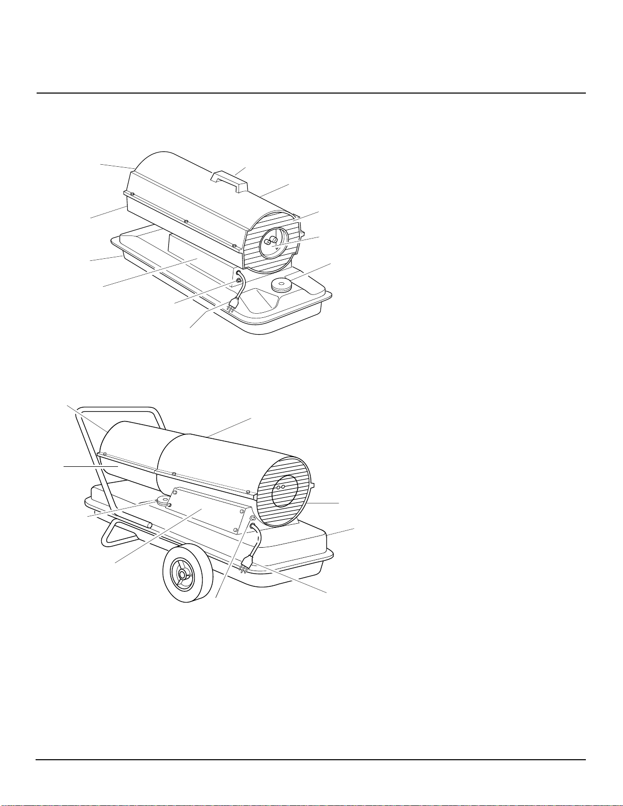
PRODUCT
IDENTIFICATION
Hot Air Outlet
Lower Shell
Fuel Tank
Side Cover
Flame-Out
Control Reset
Button
Power Cord
35/50/70,000 BTU/HR DOMESTIC
Figure 1 - 35/55,000 BTU/Hr Models
Hot Air
Outlet
Handle
PFA/PV 042
Upper Shell
Upper Shell
Fan Guard
Air Filter
End Cover
UNPACKING
1. Remove all packing items applied to
heater for shipment.
2. Remove all items from carton.
3. Check items for shipping damage. If
heater is damaged, promptly inform
dealer where you bought heater.
Fuel Cap
Lower
Shell
Fuel Cap
Side Cover
Figure 2 - 110/150,000 BTU/Hr Models
Fan Guard
Fuel Tank
Power Cord
Flame-Out
Control Reset
Button
100507
3
Page 4
PORTABLE SPACE HEATER
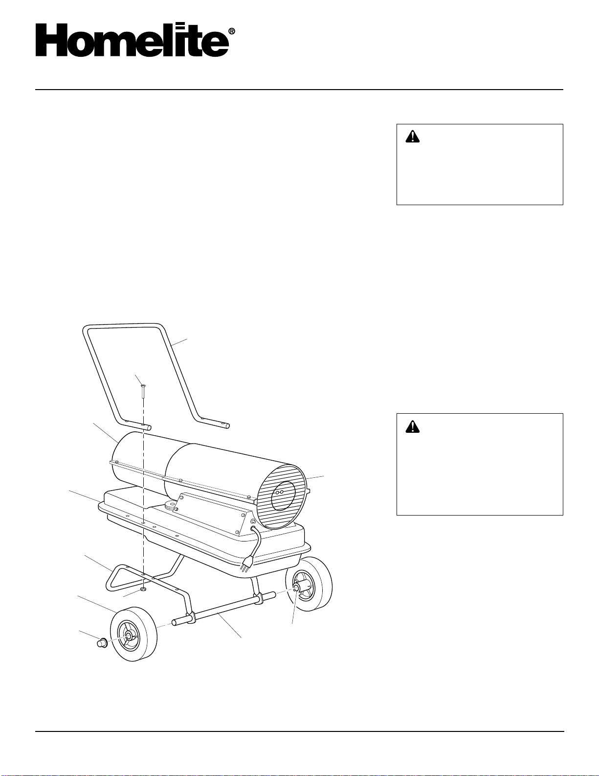
ASSEMBLY
(For 110,000 and 150,000 BTU/
Hr Models Only)
These models are furnished with wheels and
a front handle. Wheels, handle, and the
mounting hardware are found in the shipping carton.
Tools Needed
• Medium Phillips Screwdriver
• 3/8" Open or Adjustable Wrench
• Hammer
1. Slide axle through wheel support
frame. Install wheels on axle.
IMPORTANT:
point extended hub of wheels toward
wheel support frame (see Figure 3).
When installing wheels,
Front
Handle
Screw
2. Place cap nuts on axle ends. Gently tap
with hammer to secure.
3. Place heater on wheel support frame.
Make sure air inlet end (rear) of heater
is over wheels. Line up holes on fuel
tank flange with holes on wheel support frame.
4. Place front handle on top of fuel tank
flange. Insert screws through handle(s),
fuel tank flange, and wheel support
frame. Attach nut finger tight after each
screw is inserted.
5. After all screws are inserted, tighten
nuts firmly.
FUELS
WARNING: Use only kerosene
or No. 1 fuel oil to avoid risk of fire
or explosion. Never use gasoline, naphtha, paint thinners, alcohol, or other highly flammable
fuels.
Do not use heavy fuels such as No. 2 fuel oil
or No. 2 Diesel. Using heavy fuels will
result in:
• clogged fuel filter and nozzle
• carbon build-up on spark plug
• the need of non-toxic anti-icer in fuel
during very cold weather
IMPORTANT:
storage container. Be sure storage container
is clean. Foreign matter such as rust, dirt, or
water will cause the flame-out control to
shut down heater. Foreign matter may also
require you to clean fuel system often.
Use a KEROSENE ONLY
Hot Air
Outlet
Fuel
Tank
Flange
Wheel
Support
Frame
Wheel
Cap Nut
Figure 3 - Wheel and Handle Assembly, 110/150,000 BTU/Hr Models Only
Nut
Axle
Extended
Hub
Air
Inlet
VENTILATION
WARNING: Follow the minimum fresh, outside air ventilation requirements. If proper fresh,
outside air ventilation is not provided, carbon monoxide poisoning can occur. Provide proper
fresh, outside air ventilation before running heater.
Provide a fresh air opening of at least three
square feet for each 100,000 BTU/Hr rating. Provide extra fresh air if more heaters
are being used.
Example:
quires one of the following:
• a two-car garage door raised six inches
• a single-car garage door raised nine
inches
• two thirty-inch windows raised twelve
inches
A 150,000 BTU/Hr heater re-
4
100507
Page 5
OWNER’S MANUAL
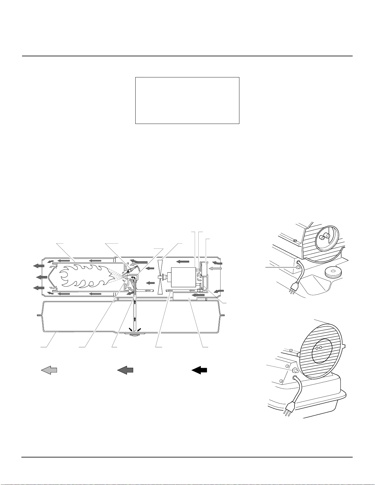
THEORY OF
OPERATION
The Fuel System: The air pump forces
air through the air line. The air is then
pushed through the burner head nozzle. This
air causes fuel to lift from the tank. A fine
mist of fuel is sprayed into the combustion
chamber.
The Air System: The motor turns the fan.
The fan pushes air into and around the
combustion chamber. This air is heated and
provides a stream of clean, hot air.
The Ignition System: The electronic
ignitor sends voltage to the spark plug. The
spark plug ignites the fuel and air mixture.
The Flame-Out Control System: This
system causes the heater to shut down if the
flame goes out.
Combustion
Chamber
Clean
Heated
Air Out
OPERATION
IMPORTANT: Review and understand the warnings in the
Information
needed to safely operate this
heater. Follow all local codes
when using this heater.
To Start Heater
1. Follow all ventilation and safety information.
2. Fill fuel tank with kerosene or No. 1
fuel oil.
3. Attach fuel cap.
4. Plug power cord of heater into threeprong, grounded extension cord. Extension cord must be at least six feet long.
Spark
Plug
Burner
Head
section. They are
Motor
Fan
Air Pump
Safety
Air
Intake
Filter
Cool
Air
In
Extension Cord Wire Size
Requirements
• 6 to 10 feet long, use 18 AWG rated
cord
• 11 to 100 feet long, use 16 AWG
rated cord
• 101 to 200 feet long, use 14 AWG
rated cord
5. Plug extension cord into standard 120
volt/60 hertz, three-hole, grounded outlet. Heater will start when extension
cord is plugged into outlet. If not, push
in flame-out control reset button (see
Figures 5 and 6).
To Stop Heater
Unplug extension cord from outlet.
To Restart Heater
1. Wait 2 minutes after stopping heater.
2. Repeat steps under To Start Heater.
FlameOut
Control
Reset
Button
Fuel
Tank
Figure 4 - Cross Section Operational View
100507
Nozzle
Air For Fuel
System
THEORY CUTAWAY
Fuel
Filter
Air Line
To Burner
Air For Combustion
And Heating
PFA/OV 003
Air
Output
Filter
Electronic
Ignitor
Fuel
5
Figure 5 - Flame-Out Control Reset Button,
35/55,000 BTU/Hr Models
Flame-Out
Control
Reset
Button
Figure 6 - Flame-Out Control Reset Button,
110/150,000 BTU/Hr Models
Page 6

PORTABLE SPACE HEATER
STORING,
TRANSPORTING,
OR SHIPPING
Note:
If shipping, transport companies re-
quire fuel tanks to be empty.
1. Drain fuel tank.
Note:
Some models have drain plug on
underside of fuel tank. If so, remove
drain plug to drain all fuel. If heater
does not have drain plug, drain fuel
through fuel cap opening. Be sure all
fuel is removed.
2. Replace drain plug if provided.
3. If any debris is noted in old fuel, add 1
or 2 quarts of clean kerosene to tank,
stir, and drain again. This will prevent
excess debris from clogging filters during future use.
4. Replace fuel cap or drain plug. Properly dispose of old and dirty fuel. Check
with local automotive service stations
that recycle oil.
5. If storing, store heater in dry place.
Make sure storage place is free of dust
and corrosive fumes.
IMPORTANT:
summer months for use during next heating
season. Using old fuel could damage heater.
Do not store kerosene over
PREVENT A TIVE
MAINTENANCE
SCHEDULE
Item
Fuel tank
Air output and
lint filters
Air intake filter
Fuel filter
Spark plug
Fan blades
Motor
How Often
Flush every 150-200 hours of operation or as needed.
Replace every 500 hours of operation or once a year.
Wash and dry with soap and water
every 500 hours of operation or replace as needed.
Clean twice a heating season or replace as needed.
Clean and regap every 600 hours
operation or replace as needed.
Clean each season or as needed
Not required/permanently lubricated
WARNING: Never service heater
while it is plugged in, operating, or
hot. Severe burns and electrical
shock can occur.
How To
See Storing, Transporting, or
Shipping, column 1.
See Air Output, Air Intake, and
Lint Filters, page 8.
See Air Output, Air Intake, and
Lint Filters, page 8
See Fuel Filter, page 9
See Spark Plug, page 10
See Fan, page 8.
6
100507
Page 7
OWNER’S MANUAL
TROUBLESHOOTING
OBSERVED FAULT
Heater ignites, but flame-out control shuts
off heater after a short period of time.
Heater will not ignite, but motor runs for a
short period of time.
WARNING: Never service heater while it is plugged in, operating, or
hot. Severe burns and electrical shock can occur.
POSSIBLE CAUSE
1. Wrong pump pressure
2. Dirty air output, air intake and lint filters
3. Dirty fuel filter
4. Dirt in nozzle
5. Dirty photocell lens
6. Bad flame-out control
WARNING: Disconnect heater cord!
1. Wrong pump pressure.
2. Carbon deposits on spark plug and/or
improper gap
3. Dirty fuel filter
4. Dirt in nozzle
5. Water in fuel tank
WARNING: High Voltage!
REMEDY
1. See Pump Pressure Adjustment, page 9
2. See Air Output, Air Intake and Lint Fil-
ters, page 8
3. See Fuel Filter, page 9
4. See Nozzle, page 11
5. Clean photocell lens
6. Replace flame-out control
1. See Pump Pressure Adjustment, page 9
2. See Spark Plug, page 10
3. See Fuel Filter, page 9
4. See Nozzle, page 11
5. Drain and flush fuel tank with clean
kerosene. See Storing, Transporting, or
Shipping, page 6.
Motor does not start when heater is plugged
in, fan rotates slowly or does not turn.
6. Electronic ignitor not grounded
7. Bad electronic ignitor
1. Flame-out control not reset
2. Solid state relay not allowed to reset
3. Binding pump rotor
6. Make sure electronic ignitor mounting
is tight.
7. Replace electronic ignitor.
1. Press flame-out control reset button.
2. Wait two minutes before trying to restart
heater.
3. If fan is hard to turn, see Pump Rotor,
page 12.
100507
7
Page 8

PORTABLE SPACE HEATER
SERVICE
PROCEDURES
WARNING: Never service
heater while it is plugged in, operating, or hot. Severe burns and
electrical shock can occur.
UPPER SHELL REMOVAL
1. Remove screws along each side of
heater using 5/16" nut-driver. These
screws attach upper and lower shells
together.
2. Lift upper shell off.
3. Remove fan guard.
Upper
Shell
Fan
Guard
FAN
IMPORTANT:
shaft before removing motor from heater.
The weight of the motor resting on the fan
could damage the fan pitch.
1. Remove upper shell (see Upper Shell
Removal).
2. Use 1/8" allen wrench to loosen setscrew which holds fan to motor shaft.
3. Slip fan off motor shaft.
4. Clean fan using soft cloth moistened
with kerosene or solvent.
5. Dry fan thoroughly.
6. (35/55/110,000 BTU/Hr Models) Replace fan on motor shaft. Place fan hub
flush with end of motor shaft (see Figure 9). (150,000 BTU/Hr Model) Replace fan on motor shaft. Make sure set
screw is touching back of flat surface
on motor shaft (see Figure 10).
7. Place setscrew on flat of shaft. Tighten
setscrew firmly (40-50 inch-pounds).
8. Replace fan guard and upper shell.
Remove fan from motor
AIR OUTPUT, AIR INTAKE,
AND LINT FILTERS
1. Remove upper shell (see Upper Shell
Removal).
2. Remove filter end cover screws using
5/16" nut-driver.
3. Remove filter end cover.
4. Replace air output and lint filters.
5. Wash or replace air intake filter (see
Preventative Maintenance Schedule,
page 6).
6. Replace filter end cover.
7. Replace fan guard and upper shell.
IMPORTANT:
Do not oil filters.
Air Intake
Filter
Filter End
Cover
Fan
Guard
Figure 7 - Upper Shell Removal, 35/55,000
BTU/Hr Models
Upper
Shell
Figure 8 - Upper Shell Removal,
110/150,000 BTU/Hr Models
Fan
Guard
Fan
Motor
Motor Shaft
Setscrew
Figure 9 - Fan Cross Section
35/55/110,000 BTU/Hr Models
Fan
Back of Flat
Surface on
Motor Shaft
Motor
Setscrew
Flush
Motor
Shaft
Lint Filter
Air Output
Filter
Figure 11 - Air Output, Air Intake, and Lint
Filters, 35/55,000 BTU/Hr Models
Air Intake
Filter
Filter End
Cover
Fan Guard
Lint Filter
Air Output
Filter
Figure 12 - Air Output, Air Intake, and Lint
Filters, 110/150,000 BTU/Hr Models
Figure 10 - Fan Cross Section
150,000 BTU/Hr Model
8
100507
Page 9

OWNER’S MANUAL
SERVICE
PROCEDURES
Continued
PUMP PRESSURE
ADJUSTMENT
1. Remove pressure gauge plug from filter
end cover.
2. Install accessory pressure gauge (part
number 00529-02).
3. Start heater (see Operation, page 5).
Allow motor to reach full speed.
4. Adjust pressure. Turn relief valve to
right to increase pressure. Turn relief
valve to left to decrease pressure. Set
pump pressure as follows:
35,000 Btu/Hr Model 3.0 PSI
55,000 Btu/Hr Model 3.4 PSI
110,000 Btu/Hr Model 4.5 PSI
150,000 Btu/Hr Model 5.0 PSI
5. Remove pressure gauge. Replace pressure gauge plug in filter end cover.
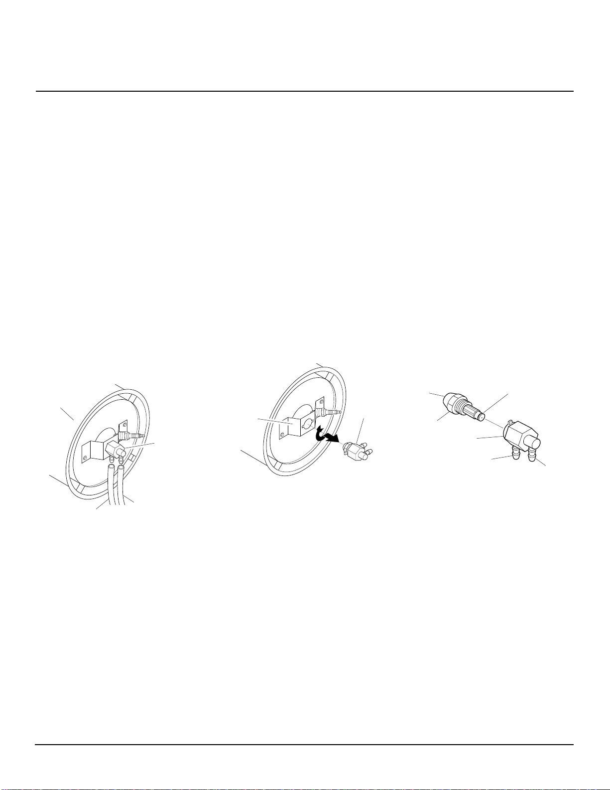
FUEL FILTER
(35/55/110/150,000 BTU/Hr
Models)
1. Remove side cover screws using 5/16"
nut-driver.
2. Remove side cover.
3. Pull upper fuel line off fuel filter neck.
4. Carefully pry bushing, fuel filter, and
lower fuel line (110/150,000 BTU/Hr
models only) out of fuel tank.
5. W ash fuel filter with clean fuel and replace in tank.
6. Attach upper fuel line to fuel filter neck.
7. Replace side cover.
Fuel Filter
Fuel Filter,
Bushing, and
Lower Fuel Line
Upper
Fuel
Line
Side Cover
Figure 16 - Fuel Filter Removal,
110/150,000 BTU/Hr Models
(35/55,000 BTU/Hr Models Shown)
Relief
Valve
Pressure
Gauge
Plug
Figure 13 - Pressure Gauge Plug Removal
Pressure
Gauge
Figure 14 - Adjusting Pump Pressure
Side Cover
Figure 15 - Fuel Filter Removal, 35/55,000
BTU/Hr Models
Upper Fuel Line
100507
Continued
9
Page 10

PORTABLE SPACE HEATER
SERVICE
PROCEDURES
Continued
SPARK PLUG
(35/55,000 BTU/Hr Models)
1. Remove upper shell (see Upper Shell
Removal, page 8).
2. Remove fan (see Fan, page 8).
3. Remove fuel and air line hoses from
nozzle assembly.
4. Remove spark plug wire from spark plug.
5. Remove two (2) screws using 5/16" nutdriver and remove burner strap.
6. Place hex-body of spark plug into vise
and tighten.
7. Remove spark plug mounting nut using 11/16" open-end wrench.
Combustion
Chamber
Air Line Hose
Figure 17 - Spark Plug Removal, 35/55,000
BTU/Hr Models
Spark Plug
Mounting Nut
Burner
Strap
Nozzle
Assembly
Fuel Line
Hose
Spark
Plug
Spark
Plug
Wire
8. Remove burner strap from spark plug.
9. Clean and regap spark plug electrodes
to .055" gap for 35,000 Btu/Hr model
and .075" gap for 55,000 Btu/Hr model.
10. Replace burner strap onto spark plug.
Rotate burner strap to position spark
plug electrodes (see Figure 19).
11. Tighten spark plug with spark plug
mounting nut.
12. Release hex-body of spark plug from vise.
13. Replace burner strap onto combustion
chamber.
14. Attach spark plug wire to spark plug.
15. Attach fuel and air line hoses to nozzle
assembly.
16. Replace fan (see Fan, page 8).
17. Replace fan guard and upper shell.
Bend Here
to Adjust
Gap
Gap
Figure 18 - Spark Plug Gap, 35/55,000
BTU/Hr Models
Burner
45°
Strap
Figure 19 - Spark Plug Rotation, 35/55,000
BTU/Hr Models Only
Spark Plug
(110/150,000 BTU/Hr Models)
1. Remove upper shell (see Upper Shell
Removal, page 8).
2. Remove fan (see Fan, page 8).
3. Remove spark plug wire from spark plug.
4. Remove spark plug from burner head
using 13/16" open-end wrench.
5. Clean and regap spark plug electrodes
to .075" gap.
6. Install spark plug in burner head.
7. Attach spark plug wire to spark plug.
8. Replace fan (see Fan, page 8).
9. Replace fan guard and upper shell.
Burner
Head
Figure 20 - Spark Plug Removal, 110/
150,000 BTU/Hr Models
Figure 21 - Spark Plug Gap, 110/150,000
BTU/Hr Models
Spark Plug Wire
Spark
Plug
Bend Here to
Adjust Gap
Gap
10
100507
Page 11
OWNER’S MANUAL
SERVICE
PROCEDURES
Continued
NOZZLE
(35/55,000 BTU/Hr Models)
1. Remove upper shell (see Upper Shell
Removal, page 8).
2. Remove fan (see Fan, page 8).
3. Remove fuel and air line hoses from
nozzle assembly.
4. Turn nozzle assembly 1/4 turn to left
and pull toward motor to remove.
5. Place plastic hex-body into vise and
lightly tighten.
6. Carefully remove nozzle from the
nozzle adapter using 5/8" socket
wrench.
7. Blow compressed air through face of
nozzle. This will free any dirt in nozzle area.
8. Inspect nozzle sleeve for damage.
Combustion
Chamber
Nozzle
Assembly
Air Line Hose
Figure 22 - Removing Air and Fuel Line
Hoses, 35/55,000 BTU/Hr Models
Fuel Line Hose
9. Replace nozzle into nozzle adapter until nozzle seats. Tighten 1/3 turn more
using 5/8" socket wrench (40-45 inchpounds).
10. Attach nozzle assembly to burner strap.
11. Attach fuel and airline hoses to nozzle
assembly.
12. Replace fan (see Fan, page 8).
13. Replace fan guard and upper shell.
NOZZLE
(110/150,000 BTU/Hr Models)
1. Remove upper shell (see Upper Shell
Removal, page 8).
2. Remove fan (see Fan, page 8).
3. Remove fuel and air line hoses from
burner head.
4. Remove spark plug wire from spark plug.
5. Remove spark plug from burner head
using 13/16" open-end wrench.
Nozzle
Burner
Strap
Figure 23 - Removing Nozzle Assembly,
35/55,000 BTU/Hr Models
Assembly
6. Remove three screws using
5/16" nut-driver and remove burner
head from combustion chamber.
7. Place burner head into vise and lightly
tighten.
8. Carefully remove nozzle from burn-er
head using 5/8" socket wrench (see Figure 26, page 12).
9. Blow compressed air through face of
nozzle. This will free any dirt in nozzle area.
10. Inspect nozzle sleeve for damage.
11. Replace nozzle into burner head and
tighten firmly (80-110 inch-pounds).
12. Attach burner head to combustion
chamber.
13. Install spark plug in burner head.
14. Attach spark plug wire to spark plug.
15. Attach fuel and airline hoses to burner
head.
16. Replace fan (see Fan, page 8).
17. Replace fan guard and upper shell.
Nozzle
Face
Nozzle
Nozzle
Adapter
Air Line
Fitting
Figure 24 - Nozzle and Nozzle Adapter,
35/55,000 BTU/Hr Models
Nozzle
Sleeve
Fuel Line
Fitting
100507
Continued
11
Page 12

PORTABLE SPACE HEATER
SERVICE
PROCEDURES
Continued
PUMP ROTOR
(Procedure if rotor is binding)
1. Remove upper shell (see Upper Shell
Removal, page 8).
2. Remove filter end cover screws using
5/16" nut-driver.
3. Remove filter end cover and air filters.
4. Remove pump plate screws using 5/16"
nut-driver.
Burner Head
Combustion
Chamber
Screw
Fuel Line Hose
Air Line Hose
Figure 25 - Removing Burner Head, 110/
150,000 BTU/Hr Models
Nozzle Face
Nozzle
Sleeve
Spark
Plug
Cable
Spark
Plug
5. Remove pump plate.
6. Remove rotor, insert, and blades.
7. Check for debris in pump. If debris is
found, blow out with compressed air.
8. Install insert and rotor.
9. Check gap on rotor. Adjust to
.003"/.004" if needed (see Figure 29).
Note:
Rotate rotor one full turn to insure the gap is .003"/.004" at tightest
position. Adjust if needed.
10. Install blades, pump plate, air filters,
and filter end cover.
Blade
Pump Plate
Insert
Rotor
Air Output
ROTOR
Figure 27 - Rotor Location, 35/55,000 BTU/
Hr Models
Filter
PFA/P 056
Fan Guard
Blade
Pump
Plate
Air Intake
Filter
Filter End
Cover
Air Intake
Filter
Filter End
Cover
11. Replace fan guard and upper shell.
12. Adjust pump pressure (see page 10).
Note:
If rotor is still binding, proceed
as follows.
13. Perform steps 1 through 6.
14. Place fine grade sandpaper (600 grit)
on flat surface. Sand rotor lightly in
“figure 8” motion four times (see Figure 30).
15. Reinstall insert and rotor.
16. Perform steps 10 through 12 above.
Gap Adjusting Screw
.003"/.004"
Gap
Measured
With
Feeler
Gauge
Blade
Gap Adjusting Screw
Figure 29 - Gap Adjusting Screw
Locations
Sandpaper
Rotor
Nozzle
Burner
Head
Air Line
Fitting
Figure 26 - Removing Nozzle, 110/150,000
BTU/Hr Models
Fuel Line
Fitting
Insert
Rotor
0 ROTOR-Domestic PFA/P 059A
Air Output
Filter
Figure 28 - Rotor Location, 110/150,000
BTU/Hr Models
Fan Guard
12
Figure 30 - Sanding Rotor
100507
Page 13

OWNER’S MANUAL
SPECIFICATIONS
Output Rating (BTU/Hr.) 35,000 55,000 110,000 150,000
Fuel Use Only Kerosene or No. 1 Fuel Oil
Fuel Tank Capacity (U.S. Gal.) 3.0 5.0 9.0 13.5
Fuel Consumption (Gal. Per Hr.) .26 .40 .82 1.10
Electric Requirements 120 V/60 Hz (Same All Models)
Amperage (Normal Run) 2.0 2.0 4.5 4.5
Hot Air Output (CFM) 165 175 490 500
WIRING DIAGRAMS
Power Plug
120V/60Hz
Red
Black
Green
Blue
Photocell
Motor
Green
Ignitor
White
White
Spark Plug
Red
Red
White
Terminal
Board
White
Figure 31 - Wiring Diagram, 35/55,000 BTU/Hr Models
Power Plug
120V/60Hz
Red
Black
Green
White
Blue
Photocell
Motor
Green
Ignitor
White
White
Spark Plug
Red
Red
White
Terminal
Board
White
White
Blue
Blue
B
Flame-
Out
Control
R
B
Flame-
Out
Control
R
Reset
Button
Reset
Button
Black
Relay
Red
Figure 32 - Wiring Diagram, 110/150,000 BTU/Hr Models
100507
13
Page 14

PORTABLE SPACE HEATER
ACCESSORIES
Purchase accessories and parts from your
nearest dealer.
AIR GAUGE KIT - 00529-02
For all models. Special tool to check pump
pressure.
STANDARD WHEELS AND
HANDLE KIT - 00529-05
Makes heater even more portable and convenient. Easy to assemble. Fits 35/55,000
BTU/Hr models.
THERMOSTAT KIT - 00529-03
For all models. Keeps your building at the
temperature you select day and night. Helps
economize on fuel.
HEAVY DUTY WHEELS AND
HANDLE KIT - 00529-04
For heavy duty applications. Makes your
heater even more portable and convenient.
Fits 35/55,000 BTU/Hr models.
14
100507
Page 15

OWNER’S MANUAL
NOTES
_______________________________________________________________________________________________
_______________________________________________________________________________________________
_______________________________________________________________________________________________
_______________________________________________________________________________________________
_______________________________________________________________________________________________
_______________________________________________________________________________________________
_______________________________________________________________________________________________
_______________________________________________________________________________________________
_______________________________________________________________________________________________
_______________________________________________________________________________________________
_______________________________________________________________________________________________
_______________________________________________________________________________________________
_______________________________________________________________________________________________
_______________________________________________________________________________________________
_______________________________________________________________________________________________
_______________________________________________________________________________________________
_______________________________________________________________________________________________
_______________________________________________________________________________________________
_______________________________________________________________________________________________
_______________________________________________________________________________________________
_______________________________________________________________________________________________
_______________________________________________________________________________________________
_______________________________________________________________________________________________
_______________________________________________________________________________________________
_______________________________________________________________________________________________
_______________________________________________________________________________________________
_______________________________________________________________________________________________
_______________________________________________________________________________________________
_______________________________________________________________________________________________
_______________________________________________________________________________________________
_______________________________________________________________________________________________
_______________________________________________________________________________________________
_______________________________________________________________________________________________
_______________________________________________________________________________________________
100507
15
Page 16

CUSTOMER ASSISTANCE
For the location of your nearest Homelite servicing dealer in the United States,
Puerto Rico, and the Virgin Islands
CALL: 1-800-242-4672
NOTE: Dealer information, technical advice, and product information can be
obtained at this number.
HEADQUARTERS
HOMELITE
P.O. BOX 7047
CHARLOTTE, N.C. 28241
OVERSEAS OFFICES
ENGLAND
HOMELITE
UNIT 22
Hither Green Trading Estate
Clevedon (Nr. Bristol)
Avon, BS 21 6XU England
FRANCE
HOMELITE
S.A.R.L.
Z.I. du Vert-Galant
Rue du Chateau/Rue de la Garenne
95310 Saint-Quen-L’Aumone
France
NETHERLANDS
(HDQS. — Europe, Africa and Middle East)
HOMELITE
Haverstraat 24
2153 GB Nieuw Vennep
The Netherlands
AUSTRALIA
HOMELITE
HEADQUARTERS
22 Terra-Cotta Drive
Blackburn, 3130
Victoria, Australia
212-214 590 Ebury Place
Delta, British Columbia
A Subsidiary of Deere & Company
CANADIAN OFFICES
HOMELITE
1850 55th Avenue
Lachine, Quebec, Canada
H8T 3J5
Annacis Island
V3M 6K7
595 Canarctic Drive
Downsview (Toronto)
Ontario, Canada
M3J 2P9
16520-111th Avenue
Edmonton, Alberta
691 Malenfant Blvd.
Dieppe Industrial Park
Dieppe, New Brunswick
inc.
T5M 3V8
E1A 5T8
100507 01
NOT A UPC
100507-01
REV. E
08/98
 Loading...