

Page 1
OPERATION MANUAL
VC3 SERIES
ELECTRIC CONVECTION OVENS
MODEL
VC3ED ML-137013
INSTALLATION &
Model VC3ED
IT W FO OD E QUI PM EN T CO MPA NY 205(.LET ,6960-10204 YK ,ELLIVSIUOL ,696 XOB .O.P ) 77 8- 27 91
FORM F47650 Rev. C (Feb. 2015) www.vulcanhart.com
Page 2

Table of Content
GENERAL . . . . . . . . . . . . . . . . . . . . . . . . . . . . . . . . . . . . . . . . . . . . . . . . . . . . . . . . . . . . . . . . . . . . . . . . . . . . . 3
INSTALLATION . . . . . . . . . . . . . . . . . . . . . . . . . . . . . . . . . . . . . . . . . . . . . . . . . . . . . . . . . . . . . . . . . . . . . . . . 4
Unpacking . . . . . . . . . . . . . . . . . . . . . . . . . . . . . . . . . . . . . . . . . . . . . . . . . . . . . . . . . . . . . . . . . . . . . . 4
Location . . . . . . . . . . . . . . . . . . . . . . . . . . . . . . . . . . . . . . . . . . . . . . . . . . . . . . . . . . . . . . . . . . . . . . . . 4
Installation Codes and Standards . . . . . . . . . . . . . . . . . . . . . . . . . . . . . . . . . . . . . . . . . . . . . . . 4
Installing Basic Oven . . . . . . . . . . . . . . . . . . . . . . . . . . . . . . . . . . . . . . . . . . . . . . . . . . . . . . . . . . . 4
Assembling the Legs to the Single Oven . . . . . . . . . . . . . . . . . . . . . . . . . . . . . . . . . . . . . . . . . 4
Leveling . . . . . . . . . . . . . . . . . . . . . . . . . . . . . . . . . . . . . . . . . . . . . . . . . . . . . . . . . . . . . . . . . . . . . . . . . 4
Casters . . . . . . . . . . . . . . . . . . . . . . . . . . . . . . . . . . . . . . . . . . . . . . . . . . . . . . . . . . . . . . . . . . . . . . . . . 4
Assembling the Stand to the Oven . . . . . . . . . . . . . . . . . . . . . . . . . . . . . . . . . . . . . . . . . . . . . 5
Electrical Connections . . . . . . . . . . . . . . . . . . . . . . . . . . . . . . . . . . . . . . . . . . . . . . . . . . . . . . . . . . 5
Assembling Stacked Ovens . . . . . . . . . . . . . . . . . . . . . . . . . . . . . . . . . . . . . . . . . . . . . . . . . . . . . 6
Electrical Connections (Stacked Ovens) . . . . . . . . . . . . . . . . . . . . . . . . . . . . . . . . . . . . . . . . . 7
OPERATION . . . . . . . . . . . . . . . . . . . . . . . . . . . . . . . . . . . . . . . . . . . . . . . . . . . . . . . . . . . . . . . . . . . . . . . . . . 8
Controls . . . . . . . . . . . . . . . . . . . . . . . . . . . . . . . . . . . . . . . . . . . . . . . . . . . . . . . . . . . . . . . . . . . . . . . . 8
Before First Use . . . . . . . . . . . . . . . . . . . . . . . . . . . . . . . . . . . . . . . . . . . . . . . . . . . . . . . . . . . . . . . . . 9
Using Models . . . . . . . . . . . . . . . . . . . . . . . . . . . . . . . . . . . . . . . . . . . . . . . . . . . . . . . . . . . . . . . . . . . 9
Standard Cooking Time Chart . . . . . . . . . . . . . . . . . . . . . . . . . . . . . . . . . . . . . . . . . . . . . . . . . . 10
Power Outage . . . . . . . . . . . . . . . . . . . . . . . . . . . . . . . . . . . . . . . . . . . . . . . . . . . . . . . . . . . . . . . . . . 10
Cleaning . . . . . . . . . . . . . . . . . . . . . . . . . . . . . . . . . . . . . . . . . . . . . . . . . . . . . . . . . . . . . . . . . . . . . . . 11
MAINTENANCE . . . . . . . . . . . . . . . . . . . . . . . . . . . . . . . . . . . . . . . . . . . . . . . . . . . . . . . . . . . . . . . . . . . . . . 11
Replacing Lamps . . . . . . . . . . . . . . . . . . . . . . . . . . . . . . . . . . . . . . . . . . . . . . . . . . . . . . . . . . . . . . 11
Service and Parts Information . . . . . . . . . . . . . . . . . . . . . . . . . . . . . . . . . . . . . . . . . . . . . . . . . . 11
VULCAN-HART COMPANY, 2000
– 2 –
Page 3
Installation, Operation and Care of
VC3 SERIES
ELECTRIC CONVECTION OVENS
KEEP THESE INSTRUCTIONS FOR FUTURE USE
Your Vulcan Electric Convection Oven is produced with quality workmanship and material. Proper
installation, usage and maintenance of your oven will result in many years of satisfactory performance. The manufacturer suggests that you thoroughly read this entire manual and carefully follow
all of the instructions provided.
GENERAL
The VC3 Series Electric Convection Ovens feature a 500°F thermostat, timer, porcelain interior and a
two-speed, 1/2 HP blower motor as standard equipment. Ovens equipped with standard voltages
are 208 or 240 V, 60 Hz, single- or three-phase. Ovens equipped for 480 V, 60 Hz, single- or
are standard. Oven light with on-o switch is standard.
An open stand with lower storage rack is available as an option.
Stacked ovens are furnished with either Stacking Kit 426983G1 (8" LEGS) or Stacking Kit 426984G1
(CASTER) for mounting one oven on top of the other.
Additional racks are available as accessories.
SNOITPO&SERUTAEF
nevO
ledoM
DE3CV
roiretnI
htpeD
1
/2"
62
)mc3.76(
141/2"
nevO
roiretxE
htpeD
S l
)mc4.501(
.ylnOsnevOdekcatSowThtiW*
tatsomrehT remiT
etatSdilo aiD.rH1 AN .tpO .tpO .dtS .tpO .tpO .tpO
tsaoR
dloH&
.rH5
NA
kcatS
tiK
remiT
htiw
sgeL
*
tiKkcatS
sgeL
htiw
htiw
*sretsaC
teeF
sgeL
htiw
sretsaC
dnatS
htiw
kcaR
teeF&
dnatS
htiw
&kcaR
sretsaC
– 3 –
Page 4
INSTALLATION
UNPACKING
Immediately after unpacking the oven, check for possible shipping damage. If the oven is found to be
damaged, save the packaging material and contact the carrier within 15 days of delivery.
plate, located on the inside of the top front cover.
Do not use the doors or their handles to lift the oven.
LOCATION
! " # $ % & ' ( ( ' & # ) $ * + % & ' ( ( ) , ' - " . + ' & " / ( " ' 0 ' $ / " 1 ) 0 % " 0 2 # / # $ 3 ' $ - ) 4 " 0 ' & # ) $ 5
6 ) 0 % ) ( # - % & ' & " ' $ - - # 3 # & ' ( ( 7 / ) $ & 0 ) ( ( " - * ) - " ( % & ! " 0 " * + % & 8 " 9 : ; < = > / * ? ) 1 / ( " ' 0 ' $ / " ) $ & ! "
0 # 3 ! & % # - " ) 1 & ! " ) 2 " $ 1 0 ) * ' $ 7 ) 4 " $ 1 ( ' * " 5 6 ) 0 ' ( ( ) & ! " 0 / ( " ' 0 ' $ / " % % " " & ' 8 ( " 8 " ( ) , 5
@ A B C D C E F B G H I E F J B G K
DCBS
V
S
W
V
X B YYBUI
@ L M N O G N A B P L E Q @ L M N O G N A B
RR
TTBUI
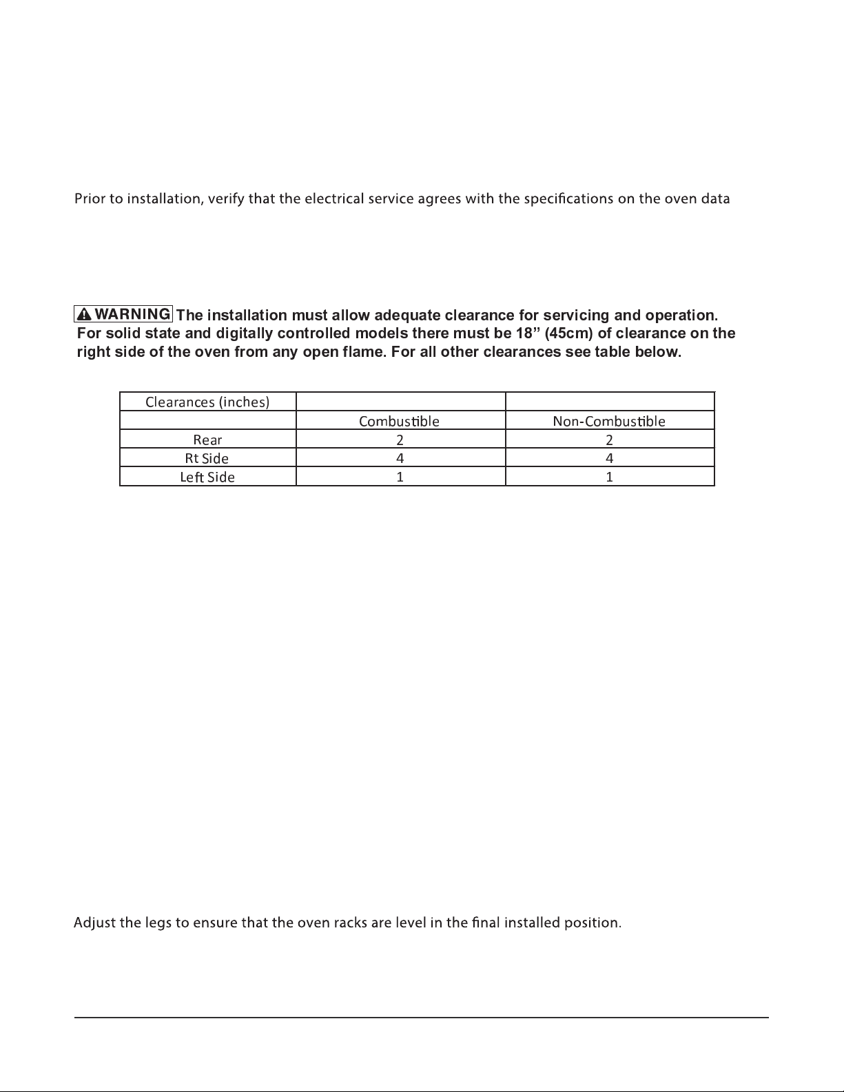
INSTALLATION CODES AND STANDARDS
In the United States,
Code, NFPA-70 (latest edition) and 3) NFPA Standard #96,
install the oven in accordance with: 1) State and local codes; 2) National Electrical
Vapor Removal from Cooking Equipment
(latest edition), available from National Fire Protection Association, Batterymarch Park, Quincy, MA
02269.
INSTALLING BASIC OVEN
The basic oven must be installed on legs or mounted on a modular stand. Installations on concrete
bases or other supports restricting air circulation underneath the oven is not advisable and may void
the warranty. If using the modular stand, set the oven on the stand after unpacking.
ASSEMBLING THE LEGS TO THE SINGLE OVEN
The legs must be installed on the bottom of the oven. Gently position the oven on its left side, taking
care not to cause scratches or damage.
Attach each of the four leg assemblies to the bottom of the oven with the 24 bolts and lockwashers
(six bolts and lockwashers per leg). Carefully raise the oven to its normal position.
LEVELING
– 4 –
Page 5

CASTERS
If the oven is to be installed on casters, assemble the
casters to the legs provided. Then attach the caster-leg
units to the oven at each corner using the 24 b olts and
lockwashers. place the locking casters on the front legs
and nonlocking casters on the rear legs. Units on casters
should be tethered to the building using the strain relief
bracket shown in Figure 2.
ASSEMBLING THE STAND TO THE OVEN
Attach each of the four leg assemblies to the bottom of the
oven with the 24 bolts and lockwashers (six per leg).
Carefully raise the oven to the normal position.
Attach the undershelf to the legs with eight bolts and
lockwashers (two per leg).
BACK
Fig. 2
Install the rack guides into the shelf at the desired locations
(for pan or
t rack), then attach the rack supports to the
top end of the rack guides. Attach rack supports to the leg
assembly by removing one middle bolt and reattaching the
back through the end holes in the rack support (Fig. 2).
ELECTRICAL CONNECTIONS
FRONT
PL-5327 4
Fig. 3
Remove the wiring compartment cover on the front of the oven. Remove the appropriate knockout on
the bottom of the oven and attach the power supply conduit to the bottom of the oven.
Comply with the appropriate wiring diagram (located inside the right side panel) when making
connections to the electrical supply lines. Use exible conduit only.
Replace the wiring compartment cover and right side panel. Turn on the power supply.
– 5 –
Page 6

ELECTRICAL DATA
208-240 V 480 V
TOTAL
Single Oven 12.5 4 4 4.5
Stacked Oven 25 8 8 9 8 8 9 70 66 70 66 58 66 28.8 30.6 30.6 120 104 52
3-PHASE LOADING 3-PHASE LOADING
KW KW PER PHASE KW PER PHASE 2 08 V 240 V 480 V
L1-L2 L2-L3 L1-L3 L1-L2 L2-L3 L1-L3
4
4
L1 L2 L3 L1 L2 L3 L1 L2 L3
4.5
35 33
NOMINAL AMPERES PER LINE WIRE
35
29 33 14.4
33
15.3 15.3
ESAHP - 1 ESAHP - 3
208 V 240 V 480 V
52
26
60
ASSEMBLING STACKED OVENS
Unpack the ovens and the stack kit. Position the ov en to be used as the bottom oven on its left side
for access to the oven bottom, taking care not to scratch or damage it.
Attach the four leg assemblies with the 24 bolts an d lockwashers (six per leg).
7
Place the lower oven (with legs) on the
and r emove two
/16" (11 mm) diameter knockouts on each
side of the top cover.
Install two locating studs to the bottom of the top oven per stacking kit instructions.
Move the oven with legs to the installed position. Place the upper oven on top of the lower oven using
the locating studs.
Remove the optional rear panel, if provided, from the TOP oven. Install the Stacking Flue (Fig. 3) with
the four screws provided. Replace the top oven rear panel, if provided.
STACKING FLUE
PL-53463
Fig. 4
– 6 –
Page 7

ELECTRICAL CONNECTIONS (Stacked Ovens)
Make sure that the electrical power supply agrees with the on the oven data plate, the
wiring diagram on the oven and Electrical Data, page 5.
1. Wires to connect both ovens are provided with each oven (X, Y, Z). Carefully route these from
top oven through the bushing (supplied with the stacking kit) through the electrical access
knockout holes common to both ovens. Wires are at least 12 AWG with a 150 degree C rating.
2. Connect wires X, Y and Z from the upper oven to the lower oven per the wiring diagram. Attach the
power supply conduit to the bottom of the lower oven. Connect the power supply leads to the
line side of the terminal block on the bottom oven.
3. Finally, inspect a
nd check all wiring and terminal connections for tightness or pinch points (cover
on oven frame).
4. Refer to reference drawing 426986 supplied with the stacking kit for electrical connection
instructions.
5. Refer to instructions supplied with the stacking kit for marking the combined electrical load
information to the electrical data plate o
f the bottom oven.
– 7 –
Page 8

! " # $ " % & % ' ( ) * + & , ) * & , " ! # ) - . * " / & , " 0 ! " % # + " , & ) ( % 1 2 / 3 " & % ( % 1 # ,
+ " , 4 # , 5 ( % 1 & % 6 5 & ( % ) " % & % / " -
CONTROLS
OPERATION
MOVE TO VENT
MASTER SWITCH
ON
OFF
OVEN COOL
HEAT
200
350
375
325
150
300
275
250
225
C
100
55
50
FAN SPEED
LOW
45
HI
150
60
F
TEMPERATURE
TIMER
OFF
400
425
450
475
500
250
0
5
10
15
20
25
303540
LIGHTS
ON
OFF
MOISTURE VENT DAMPER – The vent is alsways open for VC3E to exhaust excess moisture.
MASTER SWITCH – ON - Turns oven control circuits on.
– OFF - Turns oven control circuits
.
– OVEN COOL - Allows the fan motor to run with the doors ajar to
speed oven cooling.
ON LIGHT – Lit when MASTER SWITCH is turned to ON.
HEAT LIGHT – Comes on and goes o
when the heating elements cycle on and .
TEMPERATURE – Controls oven temperature.
gnikooc eht tes ot esU–REMIT time. Alarm sounds continuously when time
has elapsed to 0. Turn the timer OFF to silence the alarm. The timer
does not turn the oven
Keep timer set to OFF when the oven is
not in use.
FAN SPEED – Adjust air velocity in the oven cavity.
HI - Normal operating speed.
LOW - Use this setting when cooking a delicate product like
meringue, which
could blow around in the oven.
.no sthgil roiretni eht snruT - NO–STHGIL
– OFF - Turns the interior lights
.
– 8 –
Page 9

BEFORE FIRST USE
Before using the oven for the
time, it must be burned to release any odors that might result from
heating the new surfaces in the chamber.
1. Using a clean damp cloth, wipe the inside of the oven, including the racks.
2. Close the oven doors, turn the MASTER SWITCH to ON, turn the Thermostat to 300° F (149 ° C)
and allow the oven to cycle for 6 to 8 hours before turning the MASTER SWITCH to OFF.
Preheating
1. Turn MASTER SWITCH to ON. Amber ON light will come on, indicating that power to oven is on.
2. Set Thermostat as desired. Refer to COOKING GUIDELINES for suggested temperatures and
times for various products.
3. Prepare product and place in suitable pans. Wh
en white HEAT light goes
oven has reached
desired preheat temperature.
Cooking
1. Open doors and load the product into the oven. Place pans in the center of the racks. Close doors.
2. Set the Timer. After the preset time lapses, turn Timer to OFF position
to stop alarm.
3. When product is done, open doors and carefully remove cooked product from the oven. Care
should be taken when wiping up any spills, as oven is still hot.
End of Day
1. Turn Thermostat to OFF.
2. Turn MASTER SWITCH to OVEN COOL. Leave doors open while the fan is on to cool the oven.
3. Whe
n oven has cooled
turn MASTER SWITCH to OFF and clean the oven.
– 9 –
Page 10

STANDARD COOKING TIME CHART
emiT.pmeTtnuomAtcudorP
Frozen Croissant Dough 1.75 oz °F (177 ° C) 25 Min
350
053zo 57.1tnassiorC nomanniC °F (177 ° C) 35 Min.
053yarT 1sevaoL daerB llamS °F (177 ° C) 30 Min.
053.sbl 5.1sevaoL daerB egraL °F (177 ° C) 60 Min.
003yarT "62x81 )1(ekaC teehS ° F (149 ° C) 25 Min.
053yarT 1xiM enocS °F (177 ° C) 30 Min.
053yarT 1xiM niffuM °F (177 ° C) 30 Min.
053yarT 1slloR resiaK °F (177 ° C) 16 Min.
053yarT 1daerB nailatI °F (177 ° C) 40 Min.
053yarT 1*sdnuoR hsinaD °F (177 ° C) 30 Min.
053yarT 1*ekaC maerC ° F (177 ° C) 60 Min.
523yarT 1seikooC °F (163 ° C) 16 Min.
*The maximum internal cooking temperature should be 190° F (88 °C ) .
POWER OUTAGE
In case of a power outage, the oven will automatically shut down. When power is restored to the lines,
the oven will resume its normal operation. However, if the oven is to be left unattended during a power
outage, push the MASTER SWITCH to the OFF position. When power is restored to the lines, push
MASTER SWITCH to the ON position, wait for the oven to preheat, then resume normal cooking
operations.
CLEANING
' 0 * ' - $ + * ) & 1 $ ) 2 ! % / $ % ' 0 & $ 3 & % 4 & 5 $ ) & # ( & * % ! % /
! " # $ % % & # ' & ( & # ' ) ! # * ( " + , , ( - * % . , ( * # & * ' * / * ' ' 0 & . ! " # $ % % & # ' " 1 ! ' # 0 ' $ ! % . ! # * ' &
6
Clean outside of the oven daily by wiping with a clean, damp cloth.
Clean porcelain oven interior daily with soap or detergent and water. Rinse thoroughly and wipe
dry wi
! % 1 * ' & ) # * % # * + " & ' 0 & / ( * " " ' $ " 0 * ' ' & )
h a soft, clean cloth.
t
* ! ' 5 $ ) $ 3 & % . $ $ ) " ' $ # $ $ ( 4 & 5 $ ) & 1 * " 0 ! % /
7
6
, ( * " 0 ! % / $ ) " + 4 9 & ) / ! % / 0 $ ' . $ $ ) "
6 8
The doors ( when cool) may be removed by opening 90 degrees and lifting up. Clean in a dishwasher
or by hand. Allow to drip dry before replacing.
Stainless Steel Surfaces Hand Cleaning Instructions:
Soap or detergent and water usually handle routine cleaning. Rinse thoroughly and dry with a soft,
clean cloth.
For burned-on foods and greasee which resist simple soap and water cleaning, an abrasive clenser
(scouring powder) mixed into paste may be used. Apply with stainless steel wool or sponge,
always rubbing with the grain.
– 10 –
Page 11

MAINTENANCE
! " # $ " % & % ' ( ) * + & , ) * & , " ! # ) - . * " / & , " 0 ! " % # + " , & ) ( % 1 2 / 3 " & % ( % 1 # ,
+ " , 4 # , 5 ( % 1 & % 6 5 & ( % ) " % & % / " -
7 ( * / # % % " / ) " 3 " / ) , ( / & 3 * 8 + + 3 6 & % ' + 3 & / " & ) & 1 & ) ) ! " ' ( * / # % % " / ) * 0 ( ) / !
) # ( % ' ( / & ) " ) ! & ) 6 # 8 & , " 0 # , 9 ( % 1 # % ) ! " # $ " % : " 4 # , " 5 & ( % ) " % & % / " -
The fan motor comes with sealed bearings and requires no lubrication.
Annually check the vent, when cool, to be sure it is free of obstructions.
REPLACING LAMPS
1. Allow oven to cool.
2. Remove all racks by pulling forward, lifting up and out.
3.
Remove the right rack guide by swinging to 45 degree angle and pulling out.
4.
5. Replace the bulb. Gloves should be worn while handling bulbs.
6. Reassemble glass clover and racks by reversing the disassembly procedure.
SERVICE AND PARTS INFORMATION
To obtain
service and parts information concerning your VC3 Series Oven, contact the Vulcan-Hart
Service Depot in your area (refer to listing supplied with this oven) or Vulcan-Hart Company Service
Department at the address or phone number shown on the front cover of this manual.
– 11 –
.A.S.U NI DETNIRP FORM F47650 Rev. B (Sept. 2014)
 Loading...