

Page 1
INSTALLATION &
OPERATION MANUAL
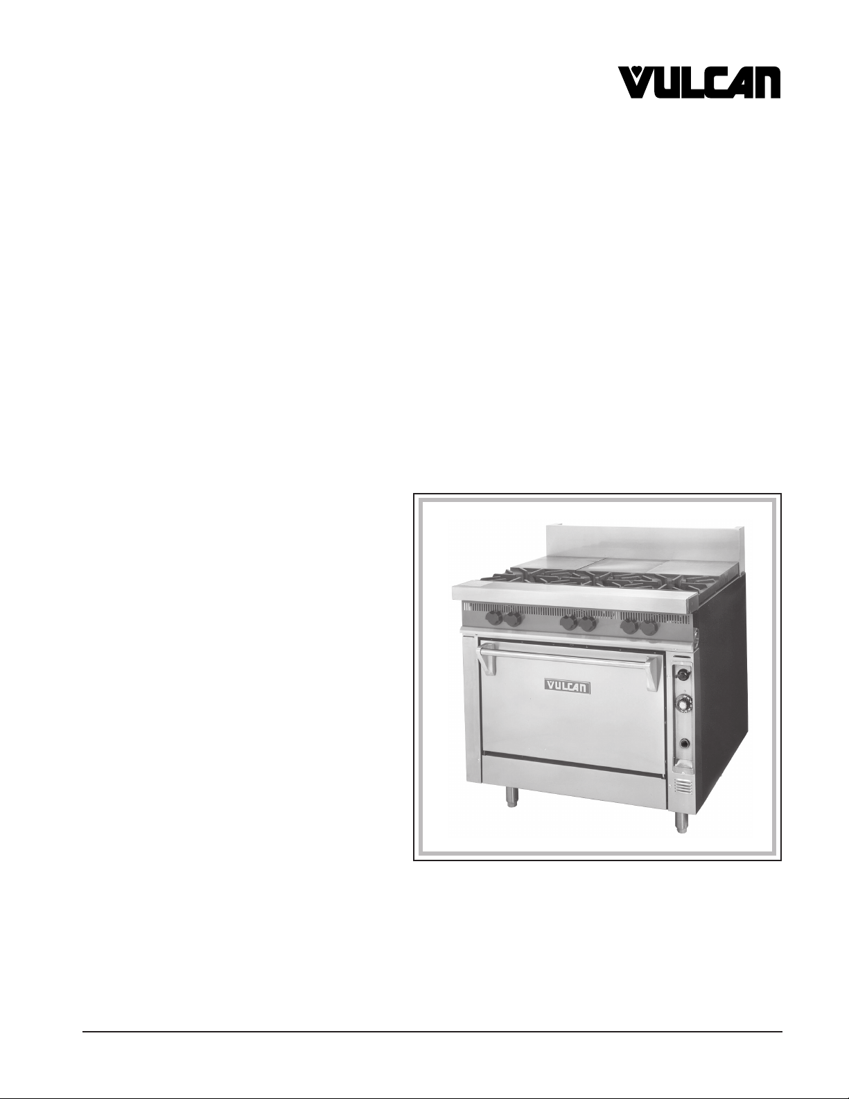
V SERIES HEAVY DUTY SECTIONAL GAS RANGE
WITH STANDARD OVEN OR SNORKEL® CONVECTION OVEN
MODELS
V36 Standard Oven W/ Standing Pilot ML-44905Z
V36 Standard Oven W/ Spark Ignition ML-44906Z
V36 Convection Oven ML-44907Z
MODEL V3HT36
VULCAN-HART COMPANY, P.O. BOX 696, LOUISVILLE, KY 40201-0696, TEL. (502) 778-2791
FORM 31165 (Jan. 2001) www.vulcanhart.com
Page 2
IMPORTANT FOR YOUR SAFETY
THIS MANUAL HAS BEEN PREPARED FOR PERSONNEL QUALIFIED TO INSTALL GAS
EQUIPMENT, WHO SHOULD PERFORM THE INITIAL FIELD START-UP AND
ADJUSTMENTS OF THE EQUIPMENT COVERED BY THIS MANUAL.
POST IN A PROMINENT LOCATION THE INSTRUCTIONS TO BE FOLLOWED IN THE
EVENT THE SMELL OF GAS IS DETECTED. THIS INFORMATION CAN BE OBTAINED
FROM THE LOCAL GAS SUPPLIER.
IMPORTANT
IN THE EVENT A GAS ODOR IS DETECTED, SHUT
DOWN UNITS AT MAIN SHUTOFF VALVE AND
CONTACT THE LOCAL GAS COMPANY OR GAS
SUPPLIER FOR SERVICE.
FOR YOUR SAFETY
DO NOT STORE OR USE GASOLINE OR OTHER
FLAMMABLE VAPORS OR LIQUIDS IN THE
VICINITY OF THIS OR ANY OTHER APPLIANCE.
WARNING
IMPROPER INSTALLATION, ADJUSTMENT,
ALTERATION OR MODIFICATION, SERVICE OR
MAINTENANCE CAN CAUSE PROPERTY
DAMAGE, INJURY OR DEATH. READ THE
INSTALLATION, OPERATING AND MAINTENANCE
INSTRUCTIONS THOROUGHLY BEFORE
INSTALLING OR SERVICING THIS EQUIPMENT.
IN THE EVENT OF A POWER FAILURE, DO NOT
ATTEMPT TO OPERATE THIS DEVICE.
© VULCAN-HART COMPANY, 2001
— 2 —
Page 3

TABLE OF CONTENTS
CONFIGURATIONS OF MODEL V SERIES HEAVY DUTY RANGES ............................................ 4
GENERAL ............................................................................................................................................ 8
INSTALLATION.................................................................................................................................... 8
Unpacking................................................................................................................................. 8
Location .................................................................................................................................... 9
Installation Codes and Standards ........................................................................................... 9
Ranges Mounted on Casters................................................................................................. 10
Leveling .................................................................................................................................. 10
Connection of Manifolds in Battery ....................................................................................... 11
Installing Overlapping Griddle Top ....................................................................................... 12
Gas Connections.................................................................................................................... 12
Testing the Gas Supply System ............................................................................................ 12
Flue Connections ................................................................................................................... 13
Electrical Connections ........................................................................................................... 13
Lighting and Shutting Down Pilots ........................................................................................ 13
OPERATION ...................................................................................................................................... 15
Before First Use ..................................................................................................................... 15
Controls .................................................................................................................................. 15
Operating Suggestions .......................................................................................................... 15
A Guide for Cooking Times and Temperatures.................................................................... 17
Cleaning.................................................................................................................................. 19
MAINTENANCE ................................................................................................................................. 22
Pilot Lights .............................................................................................................................. 22
Lubrication .............................................................................................................................. 22
Gas Odor ................................................................................................................................22
Flue ......................................................................................................................................... 22
Service Frequency ................................................................................................................. 22
Service and Parts Information ............................................................................................... 22
TROUBLESHOOTING ....................................................................................................................... 23
Oven........................................................................................................................................ 23
Top Burner Operation ............................................................................................................ 24
— 3 —
Page 4
V436
V436C
V436M
V436S
V41H36
12"
HT
12"HT 12"HT 12"
HT
V41H36C
V41H36M
V41H36S
V2G236
V2G236C
V2G236M
V2G236S
V2G1H36
V2G1H36C
V2G1H36M
V2G1H36S
24"
G
18"HT 18"
HT
12"
HT
12"
HT
12"
HT
24"
G
V2H36
V2H36C
V2H36M
V2H36S
V21H36
V21H36C
V21H36M
V21H36S
V636
V636C
V636M
V636S
V3036
"V" SERIES
MODULAR RANGE
"V" SERIES
FULL BODY
36" WIDE
V3036C
V3036M
V3036S
V1G236
V1G236C
V1G236M
V1G236S
V1G436
V1G436C
V1G436M
V1G436S
18"
G
18"G 18"
HT
12"
G
V1G1H36
V1G1H36C
V1G1H36M
V1G1H36S
V1G2H36
V1G2H36C
V1G2H36M
V1G2H36S
12"G 12"HT 12"
HT
V3H36
V3H36C
V3H36M
V3H36S
12"HT 12"HT 12"
HT
18"
HT
18"
18"
V2HT36
V2HT36C
V2HT36M
V2HT36S
V23036
V23036C
V23036M
V23036S
G
36"
18"HT 18"
HT
V3G36
V3G36C
V3G36M
V3G36S
V3HT 36
V3HT36C
V3HT36M
V3HT36S
V22H36
V22H36C
V22H36M
V22H36S
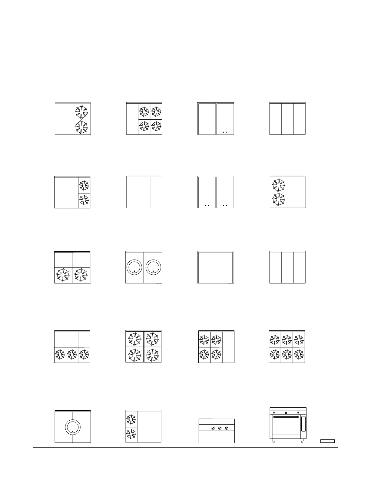
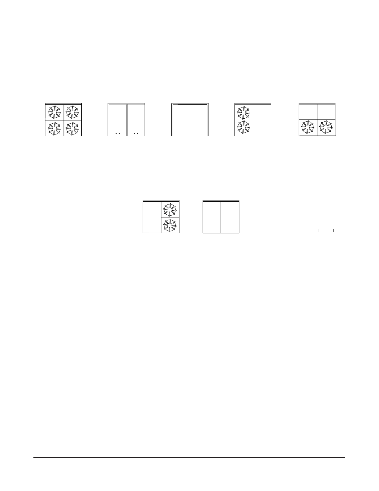
CONFIGURATIONS OF MODEL "V" SERIES HEAVY DUTY
RANGES WITH STANDARD AND CONVECTION OVENS
AND MODULAR RANGES.
PL-53598
— 4 —
Page 5
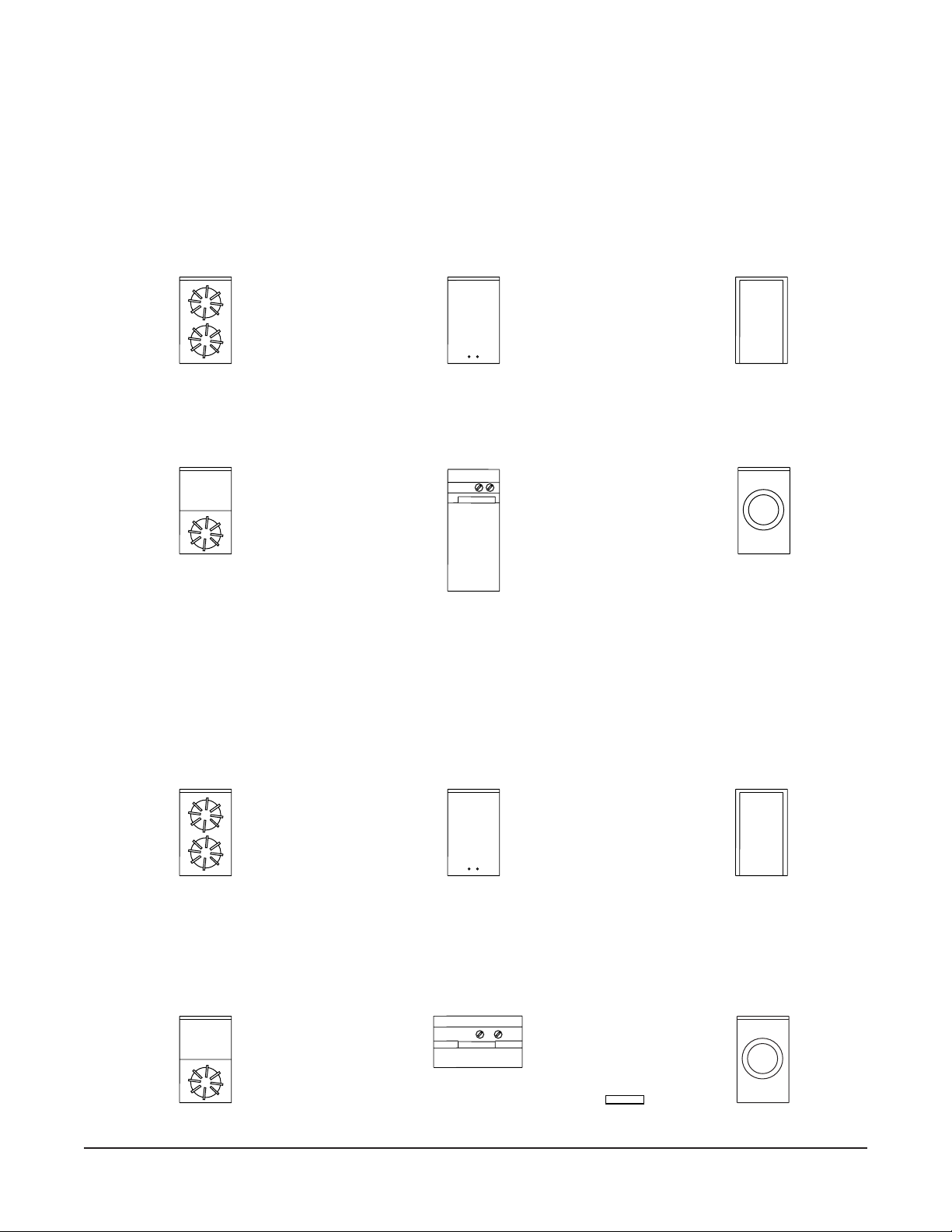
CONFIGURATIONS OF MODEL "V" SERIES
12" & 18" HEAVY DUTY EXPANDO & MODULAR RANGES
MODEL "V" SERIES EXPANDO RANGES WITH CABINETS
V212S
V218S
V1HT12S
V1HT18S
HT
V1H12S
V1H18S
HT
"V" SERIES 18" WIDE
FULL BODY WITH
CABINET
V1G12S
V1G18S
G
V13018S
V212M
V218M
V1HT12M
V1HT18M
HT
MODEL "V" SERIES MODULAR EXPANDO RANGES
V1H12M
V1H18M
HT
18" WIDE
MODULAR RANGE
PL-53599
V1G12M
V1G18M
G
V13018M
— 5 —
Page 6
CONFIGURATIONS OF MODEL "V" SERIES 24" HEAVY DUTY
EXPANDO AND MODULAR RANGES
V424S
V424M
V2H24
V2H24M
12"HT 12"
HT
V1G224S
V1G224M
12"
G
V1G24S
V1G24M
G
V1G1H4S
V1G1H4M
12"G 12"
HT
V21H24S
V21H24M
12"
HT
V2HT24S
V2HT24M
12"HT 12"
HT
PL-53600
— 6 —
Page 7
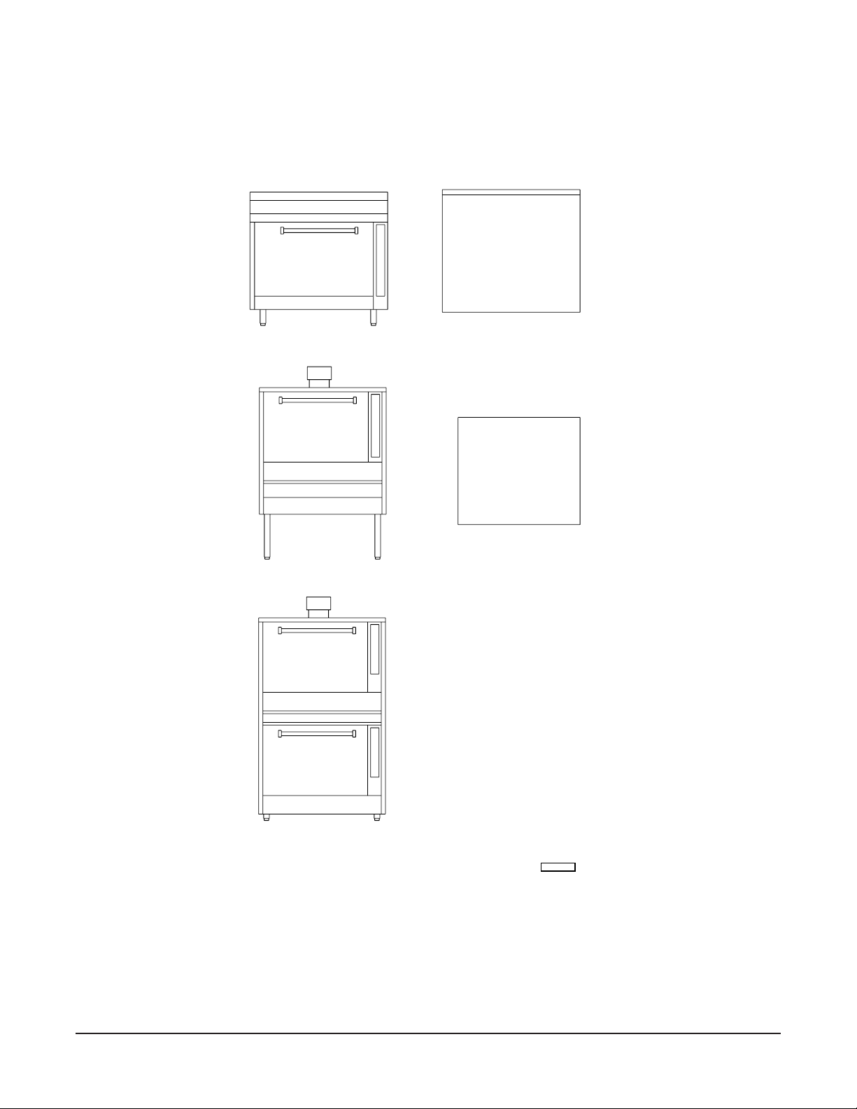
CONFIGURATIONS OF "V" SERIES HEAVY DUTY OVENS
VO36
SINGLE
OVEN
WORK TOP VIEW
VO36C
SINGLE
CONVECTION
OVEN
OVEN
ON MODULAR
STAND
VO236
DOUBLE
STACKED
OVEN
PL-53601
— 7 —
Page 8

Installation, Operation and Care Of
MODEL V SERIES HEAVY DUTY SECTIONAL GAS
RANGES WITH STANDARD OVEN OR SNORKEL
®
CONVECTION OVEN
PLEASE KEEP THIS MANUAL FOR FUTURE REFERENCE
GENERAL
Vulcan ranges and ovens are produced with quality workmanship and material. Proper installation,
usage and maintenance of your range will result in many years of satisfactory performance.
The manufacturer suggests that you thoroughly read this entire manual and carefully follow all of the
instructions provided.
INSTALLATION
UNPACKING
This range was inspected before leaving the factory. The transportation company assumes full
responsibility for safe delivery upon acceptance of the shipment. Immediately after unpacking, check
for possible shipping damage. If the range is found to be damaged, save the packaging material and
contact the carrier within 15 days of delivery.
Carefully unpack range(s) and place in the approximate installation position, whether as a battery or
single stand-alone range.
Remove parts (packed in a cardboard box) from oven cavity, or cabinet body, or on top of modular
range(s).
Remove wire or nut from rear of each burner before installing the range.
Before installing, check the electrical service (Convection Oven Models only) and type of gas supply
(natural or propane) to make sure they agree with the specifications on the rating plate located on the
inside of the burner box lower panel. The rating plate will show the voltage, phase, cycle, full load
ampere, BTU, as well as the type of gas. If the supply and equipment requirements do not agree, do
not proceed with the installation. Contact your dealer or Vulcan-Hart Company immediately.
— 8 —
Page 9

LOCATION
CAUTION: The equipment area must be kept free and clear of combustible substances.
The minimum installation clearances from combustible and noncombustible construction for ranges
using inputs of 30,000 Btu/Hr per open top burner are:
Combustible Noncombustible
Sides 20" (51 cm) 0"
Rear 2" (5 cm) 0"
The minimum installation clearances from combustible and noncombustible construction for ranges
using inputs of 20,000 Btu/Hr per open top burner are:
Combustible Noncombustible
Sides 6" (15 cm) 0"
Rear 2" (5 cm) 0"
The ranges are suitable for installation on combustible floors when 6" (15 cm) adustable legs are used.
When legs are removed, use only on noncombustible floors, curb, or platform, with front appliance
projecting 3" (8 cm) beyond curb or platform.
Ranges with Snorkle ovens should be installed on 6" (15 cm) legs or casters, allowing 6" (15 cm)
clearance from the rear of the range. If ranges with Snorkle ovens are installed directly on curbs,
without legs, or in back-to-back installations, provisions must be made for adequate air circulation,
and these provisions must be approved by Vulcan-Hart Company Service Department. Contact
Vulcan-Hart Company at the address or phone number shown on the front cover of this manual.
All modular ranges are to be installed only on non-combustible floors.
The installation location must allow adequate clearances for servicing and proper operation. A
minimum front clearance of 35" (88 cm) is required.
The range(s) must be installed so that the flow of combustion and ventilation air will not be obstructed.
Adequate clearance for air openings into the combustion chamber(s) must be provided. Make sure
there is an adequate supply of air in the room to allow for combustion of the gas at the burners.
INSTALLATION CODES AND STANDARDS
Your Vulcan range(s) must be installed in accordance with:
In the United States:
1. State and local codes.
2. National Fuel Gas Code, ANSI/Z223.1 (latest edition), available from American Gas Association,
Inc., 1515 Wilson Blvd., Arlington, VA 22209.
3. National Electrical Code ANSI/NFPA-70 (latest edition). Copies available from The National Fire
Protection Association, Batterymarch Park, Quincy, MA 02269.
— 9 —
Page 10

In Canada:
1. Local codes.
2. CAN/CGA-B149.1 Natural Gas Installation Code (latest edition).
3. CAN/CGA-B149.2 Propane Installation Code (latest edition), available from The Canadian Gas
Association, 178 Rexdale Blvd., Etobicoke, Ontario, Canada M9W 1R3.
4. Canadian Electrical Code, CSA C22.2 No. 3 (latest edition). Copies may be obtained from The
Canadian Standard Association, 178 Rexdale Blvd., Etobicoke, Ontario, Canada M9W 1R3.
RANGES MOUNTED ON CASTERS
When ranges are mounted on casters, you must use a connector (available from Vulcan-Hart) that
complies with the Standard for Connectors of Movable Gas Appliances, ANSI-Z21.69 (latest edition),
and a quick-disconnect device that complies with the Standard for Quick-Disconnect Devices
Complying With Gas Fuel, ANSI-Z21.41 (latest edition) or CAN 1-6.9 (latest edition).
Provide a gas line strain relief to limit movement of the range(s) without depending on the connector
and/or any quick-disconnect device or its associated piping to limit movement of the range(s). Attach
the strain relief to the rear of the range (Fig. 1).
Should it be necessary to disconnect the strain relief, turn off the gas supply before disconnection.
Reconnect the strain relief before turning the gas supply on and returning the range(s) to their
installation position.
CONNECT GAS LINE
STRAIN
RELIEF HERE
PL-51219
Fig. 1
LEVELING
Curb Installation
Ranges must overhang curb 3" (8 cm) in front. To level each range, remove oven bottom. Adjust four
corner leveling bolts as required to level the appliance on all sides.
— 10 —
Page 11

Snorkel Oven
Remove lower front kick plate. Remove two screws holding electric gas valve and move valve off to
the side. Pull oven burner out of compartment through opening. Adjust four corner bolts to level range.
Replace burner valve and kick plate.
Floor Installation on Legs
The 6" (15 cm) adjustable legs must be tightened securely. Level each range by turning the foot
portion of the adjustable legs.
Lining up Range Battery
In batteries of ranges, it is recommended that the center range be installed and leveled first. Level
each range, one at a time, to line up high shelf and roll front with adjacent range. Bolt the high
shelves
and roll fronts together.
CONNECTION OF MANIFOLDS IN BATTERY
Two or more ranges can be coupled together at the manifold by removing the front control panel to
make necessary connections. Be sure to cap open ends. To connect:
1. Adjust manifold by loosening U-bolts. In a large battery of eight or more ranges, gas should be
fed from both ends of the battery. "T" gas connections can be installed whenever necessary for
increased gas supply. For further details, consult your gas company. The top roll front may also
be removed for your convenience.
2. Bolt risers together at top rear.
3. If risers have high shelves, bolt the high shelf brackets together. Replace the high shelves.
4. Use clamp to pull ranges together at the rear. (There is a slotted hole in the top frame side at
the rear that can be used to bolt ranges together if necessary. Run a
the slotted hole, drilling from inside out on each range.) Use
1
5
/16" diameter drill through
/4"-2 x 2" bolt that is provided.
5. Replace all top sections. Make manifold union connections at the front. Do not allow manifold
pipe to turn.
6. Bolt the roll front ends together at the front. (Make sure roll fronts match.) Use
1
/4"-20 x 1" bolts
provided.
7. Tighten the front roll front bolts after the roll front ends have been properly bolted together.
8. Before replacing manifold panels, check all gas connections for leaks. (See GAS CONNECTIONS
in this manual.)
If appliance has rear gas connection, carefully check for open gas lines.
The gas pressure regulator must have proper outlet pressure capacity for this battery application.
— 11 —
Page 12

INSTALLING OVERLAPPING GRIDDLE TOP
1. Bolt ranges together and level per instructions in this manual.
2. Remove chrome bull noses from ranges receiving overlapping griddle tops. Bull noses are held
by bolts on the bottom side.
3. MANUAL CONTROLS ONLY — Set griddle tops in place and level with bolts located under the
griddle top in both rear corners. Should you desire griddle plate to slope forward, adjust
accordingly. Make sure hole in front gutter fits into cast iron drain in range. Reinstall bull noses.
4.
THERMOSTAT CONTROL ONLY — Set griddle top in place and support front with 4" to 6"
cm to 15 cm) blocks. Insert thermostat probe into smaller of two angles on bottom of griddle
(10
top (bend probe slightly while inserting to hold in place). Slide insulation sleeving around probe
lead up to angle on griddle top. Coil excess lead near thermostat, leaving as little as possible
in burner area. Make sure that thermostat probe lead is not over burner or pilot flame. Remove
supporting blocks and lower griddle top in place.
Level griddle top with bolts located under both rear corners. Should you desire griddle plate to
slope forward, adjust accordingly. Make sure hole in front gutter fits into cast iron drain in range.
Reinstall bull noses.
Leveling bolts are provided under each griddle plate at the rear, should you desire griddle plate to slope
forward. Top frame sealing channels are supplied to seal off any space between two or more ranges.
GAS CONNECTIONS
CAUTION: All gas supply connections and any pipe joint compound used must be resistant to
the action of propane gases.
This appliance must be connected with a gas supply line as large or larger ID (net inside diameter) than
the gas pipe inlet provided on the rear of the appliance. Connect gas supply to the range(s). Make sure
the pipes are clean and free of obstructions, dirt, and piping compound.
Codes require that a gas shutoff valve be installed in the gas line ahead of the range(s).
Ranges manufactured for use with propane gas are equipped with fixed orifices.
A gas pressure regulator must be furnished by the installer or plumber at the time of installation. The
regulator must be listed by a nationally recognized testing agency. These appliances are rated at the
following pressure: Natural Gas - 5" W.C. (Water Column) (1.25 kPa); Propane Gas - 10" W.C. (2.49 kPa).
WARNING: PRIOR TO LIGHTING, CHECK ALL JOINTS IN THE GAS SUPPLY LINE FOR LEAKS.
USE SOAP AND WATER SOLUTION. DO NOT USE AN OPEN FLAME.
After piping has been checked for leaks, all piping receiving gas should be fully purged to remove air.
TESTING THE GAS SUPPLY SYSTEM
When test pressures exceed
1
/2 psig (3.45 kPa), the range and its individual shutoff valve must be
disconnected from the gas supply piping system.
When test pressures are
1
/2 psig (3.45 kPa) or less, the range must be isolated from the gas supply
system by closing its individual manual shutoff valve.
— 12 —
Page 13

FLUE CONNECTIONS
DO NOT obstruct the flow of flue gases from the flue duct located on the rear of the range. It is
recommended that the flue gases be ventilated to the outside of the building through a ventilation
system installed by qualified personnel.
A minimum of 18" (45 cm) must be maintained between the ventilation system and the cooking surface.
Information on the construction and installation of ventilating hoods may be obtained from the standard
for "Vapor Removal from Cooking Equipment," NFPA No. 96 (latest edition), available from the
National Fire Protection Association, Batterymarch Park, Quincy, MA 02269.
ELECTRICAL CONNECTIONS
WARNING: ELECTRICAL AND GROUNDING CONNECTIONS MUST COMPLY WITH THE
APPLICABLE PORTIONS OF THE NATIONAL ELECTRICAL CODE AND/OR OTHER LOCAL
ELECTRICAL CODES.
WARNING: DISCONNECT ELECTRICAL POWER SUPPLY AND PLACE A TAG AT THE
DISCONNECT SWITCH TO INDICATE YOU ARE WORKING ON THE CIRCUIT.
WARNING: APPLIANCES EQUIPPED WITH A FLEXIBLE ELECTRIC SUPPLY CORD ARE PROVIDED
WITH A THREE-PRONG GROUNDING PLUG. IT IS IMPERATIVE THAT THIS PLUG BE CONNECTED
INTO A PROPERLY GROUNDED THREE-PRONG RECEPTACLE. IF THE RECEPTACLE IS NOT
THE PROPER GROUNDING TYPE, CONTACT AN ELECTRICIAN. DO NOT REMOVE THE
GROUNDING PRONG FROM THIS PLUG.
Do not connect the range to electrical supply until after gas connections have been made.
LIGHTING AND SHUTTING DOWN PILOTS
Open Top, Griddle Top, Hot Top, Broiler and Cheesemelter Pilots
1. Turn the main burner valve to the ON position.
2. Turn all burner valves and pilot adjustment valves to the OFF position. Wait 5 minutes.
3. Turn pilot adjusting valve screw counterclockwise, then light the pilot adjacent to each burner.
Adjust each pilot screw until the pilot flame is
1
/4" (0.6 cm) high.
4. If pilot fails to light, repeat steps 1-3 above.
5. For a complete shutdown, turn all burner valves to the OFF position. Turn all pilot valve screws
clockwise until the pilot flames go out. Turn gas shut-off valve OFF.
— 13 —
Page 14

Standard Oven With Standing Pilot (Fig. 2)
1. Turn Thermostat and Shut-off Valve to the OFF position.
2. Wait 5 minutes.
3. Remove lower panel.
4. Depress Red Button on safety valve and light pilot through
observation hole.
5. Hold down Red Button for at least 30 seconds.
6. When button is released, pilot should remain lit. Pilot
flame may be adjusted with screw on pilot adjustment
valve on pilot supply tubing located behind the control
panel. There should be only a slight amount of yellow in
the properly adjusted pilot flame.
7. Replace lower panel.
8. Turn Shut-off Valve to the ON position and turn the
Thermostat to the desired temperature.
9. If pilot flame becomes extinguished, repeat the above
procedure.
10. For a complete shutdown, turn the Thermostat, Shut-off
Valve, and gas shut-off valve to the OFF position.
SHUT-OFF
VALVE
THERMOSTAT
RED BUTTON
(SAFETY)
Fig. 2
PL-53512
Standard Oven with Electric Ignition (Fig. 3)
1. Turn Thermostat and Shut-off Valve to OFF position.
Wait 5 minutes.
2. Turn Shut-off Valve to ON position.
3. Turn Thermostat to desired setting.
4. Oven burner lights automatically.
5. For a complete shutdown, turn the Thermostat, Shut-off
Valve, and gas shut-off valve to the OFF position.
SHUT-OFF
VALVE
THERMOSTAT
PL-53513
Fig. 3
— 14 —
Page 15

Snorkle Convection Oven with Standing Pilot (Fig. 4)
1. Turn Thermostat and Shut-off Valve to OFF position.
Wait 5 minutes.
2. Turn Shut-off Valve to ON position.
3. Remove the lower front panel. Flip up the window that
covers the pilot lighting hole and light the pilot with a lit
taper. Flip window back in place and replace lower front
panel.
4. Turn Thermostat to desired setting.
5. Turn Fan Switch to ON position.
SHUT-OFF
VALVE
THERMOSTAT
FAN SWITCH
FAN
6. Oven burner lights automatically.
7. For a complete shutdown, turn Thermostat, Shut-off
Valve, Fan Switch, and gas shut-off valve to the OFF
position.
Snorkle Convection Oven with Electric Ignition (Fig. 5)
1. Turn Thermostat and Shut-off Valve to the OFF position.
Wait 5 minutes.
2. Turn Shut-off Valve to ON position.
3. Turn Fan Switch to ON.
4. Turn Thermostat to desired setting.
5. Oven burner lights automatically.
SHUT-OFF
VALVE
THERMOSTAT
FAN SWITCH
PL-53514
Fig. 4
FAN
6. For a complete shutdown, turn Thermostat, Fan Switch,
Shut-off Valve, and gas shut-off valve to the OFF
position.
— 15 —
PL-53515
Fig. 5
Page 16

OPERATION
WARNING: THE RANGE AND ITS PARTS ARE HOT. BE CAREFUL WHEN OPERATING, CLEANING
OR SERVICING THE RANGE.
BEFORE FIRST USE
Griddle Tops: Before using your Vulcan griddle, the protective coating that was applied at the factory
must be completely removed with a commercial degreaser. After a thorough cleaning, apply a high
temperature, salt-free frying oil and you are ready to use your Vulcan griddle.
The griddle requires no "breaking-in" or "seasoning."
CONTROLS
Range Top Valve
Oven Shut-off Valve Allows gas to flow to the oven burner. To open
Red Button
(Standard Oven Only)
Thermostat Regulates the oven temperature. The thermostat temperature
Fan Switch Turns fan on and off. (See Fig's. 4 and 5.)
OPERATING SUGGESTIONS
Standard Oven: If you have a standard oven, use your normal recipe times and temperatures.
®
Snorkel
with less energy consumption. The oven pre-heats faster, and baking time, temperature settings, and
shrinkage are reduced.
In general, reduce temperature 25°F (10°C) from conventional recipes.
Convection Oven: The Vulcan Snorkle® Oven does everything a regular oven can do, but
Allows gas to flow to the range section. To open valve, turn knob
counterclockwise. To close valve, turn knob
counterclockwise. To close valve, turn knob
Fig’s. 2, 3, 4, and 5.)
Allows gas to flow to the oven pilot. To operate, push button
in and
range is from 150°F to 500°F
counterclockwise to increase temperature and clockwise to decrease
temperature. (See Fig’s. 2, 3, 4, and 5.)
follow pilot lighting instructions (See Fig. 2).
(65°C to 260°C). Turn thermostat
clockwise.
valve, turn knob
clockwise. (See
• Bakery Products: Reduce temperature 25°F. Reduce time by 25% to 33%.
• Casserole Cookery: Reduce temperature about 25°F, and time by 25% to 50%.
• Meat Roasting: Reduce temperature to 275-300°F (135-149°C). Use meat thermometer.
Cooking time may be reduced up to 50%.
Use fan for preheating and baking.
Place open-face pies with thin filling mixture in preheated oven 2 to 3 minutes before turning on fan
switch.
Check product at half the time of the regular recipe.
Level pans bake more evenly; warped pans will give uneven baking results.
— 16 —
Page 17

A GUIDE FOR COOKING TIME & TEMPERATURES
The following lists are suggested cooking times and temperatures for convection and standard ovens. These guidelines, which will
vary depending on product temperature, size, shape, etc., are suggestions only and should be adjusted to suit your operation.
(CONVECTION OVEN ONLY)
Suggested Your
Suggested Temperature Your Temp.
Time °F (°C) Time °F (°C)
MEAT, POULTRY, FISH
Roasting 10-15 min./lb (.45 kg) 250-300 (121-149) __________ __________
Braising 20-25 min./lb (.45 kg) 300 (149) __________ __________
Cafeteria Beef Rounds (45 lb./20 kg) 9 hours 225 (107) __________ __________
Steaks (11/2" [4 cm] thick) 10-14 min. 450 (232) __________ __________
Meat Loaf (41/4" x 9" / 11 x 23 cm) 45-60 min. 300 (149) __________ __________
Hamburger Patties 4-8 min. 400 (204) __________ __________
Bacon 6-10 min. 400 (204) __________ __________
Sausage Links 8-12 min. 400 (204) __________ __________
Turkey (24 lb. / 11 kg) 21/2-3 hours 300 (149) __________ __________
Oven Browned Chicken Parts 40-45 min. 350 (177) __________ __________
Fish Fillets (4 oz. [.1 kg] frozen) 20-25 min. 475 (246) __________ __________
Fish Sticks (1 oz. [28 gr.] frozen) 10 min. 400 (204) __________ __________
BAKED PRODUCTS
Sheet Cakes (18" x 26"/46 x 66 cm) 20 min. 325 (163) __________ __________
Bar Cookies 15-20 min. 325 (163) __________ __________
Drop Cookies 8-12 min. 350 (177) __________ __________
Pie Crust 8-10 min. 400 (204) __________ __________
Fruit Pies 30 min. 375 (190) __________ __________
Custard-type Pies 30-45 min. 300-325 (149-163) __________ __________
Meringue, topping for pies 8-10 min. 325 (163) __________ __________
Fruit Cobbler 30-45 min. 350 (177) __________ __________
Cornbread 20 min. 350 (177) __________ __________
Biscuits 8-10 min. 375-400 (190-204) __________ __________
Muffins 12-15 min. 300 (149) __________ __________
Yeast Rolls 10-15 min. 300-325 (149-163) __________ __________
Danish Rolls 10 min. 350 (177) __________ __________
Sweet Rolls 10-15 min. 300 (149) __________ __________
Hamburger Buns 20 min. 325 (163) __________ __________
Yeast Bread 20-30 min. 325 (163) __________ __________
MISCELLANEOUS PRODUCTS
Baked Potatoes (200, 6-8 oz. [.2kg] 45-60 min. 450 (232) __________ __________
Toasted Cheese Sandwiches 8-10 min. 350 (177) __________ __________
Toasty Dog Sandwiches 12 min. 350 (177) __________ __________
Casseroles (12 x 20 x 2" / 20 min. 350 (177) __________ __________
[39 x 51 x 5 cm] pan)
Casseroles (12 x 20 x 4" / 30 min. 275 (135) __________ __________
[30 x 51 x 10 cm] pan)
Rice, covered 30 min. 325 (163) __________ __________
(3 lb. [1.4kg] per 12x20x2" /
[30 x 51 x 5 cm] pan)
FROZEN FOOD PRODUCTS
Fruit Pies 30 min. 400 (204) __________ __________
Pot Pies, individual 20-30 min. 400 (204) __________ __________
Casseroles, covered (12 x 20 x 2" / 45 min. 400 (204) __________ __________
[30 x 51 x 5 cm] pan)
Casseroles, refrigerator thawed 30 min. 450 (232) __________ __________
(12 x 20 x 2" / [30 x 51 x 5 cm] pan)
Dinners, individual, covered 10-15 min. 350 (177) __________ __________
Vegetables, covered 20-30 min. 400 (204) __________ __________
(5 lb. [2kg] per 12 x 20 x 2" /
[30 x 51 x 5 cm] pan)
— 17 —
Page 18

A GUIDE FOR COOKING TIME AND TEMPERATURES
Baking Times at Preheated Oven Temperatures
TEMPERATURE TEMPERATURE TIME
PRODUCT °F (°C) °F (°C) Total Minutes
MEAT
Braised Meats 350 (177) 325 (163) 20-22
Meat in Casserole 330 (166) 300 (149) 20-22
Meat Pie with Crust 450 (232) 425 (218) 30-35
(meat previously cooked)
Rare 300 (149) 275 (135) 140 (60) 18-20 (covered)
Medium 300 (149) 275 (135) 160 (71) 22-25 (covered)
Well Done 300 (149) 275 (135) 170 (77) 27-30 (covered)
Pork
Fresh (always well done) 350 (177) 325 (163) 185 (85) 30-35
Smoked 300 (149) 275 (135) 170 (77) 25-30
Lamb and Mutton
Medium 300 (149) 275 (135) 175 (79) 25-30
Well Done 300 (149) 275 (135) 180 (82) 30-35
Veal 325 (163) 300 (149) 170 (77) 25-35
Poultry 325-350 (163-177) 300-325 (149-163) 22-30 (covered)
Chicken 325-350 (163-177) 300-325 (149-163) 20-25 (covered)
Duck, Goose 325-350 (163-177) 300-325 (149-163) 15-25 (covered)
Turkey 325-350 (163-177) 300-325 (149-163) 15-25 (covered)
Fish Total Minutes
Small or Fillets 350-375 (177-190) 325-350 (163-177) 20-25
Large 350 (177) 325 (163) 15-20
Lobster, Stuffed 350 (177) 325 (163) 15-20
VEGETABLES
Beans with Pork 250-350 (121-177) 225-325 (107-163) 6-8 hours
Eggplant, Stuffed 325 (163) 300 (149) 60
Mushrooms 400-450 (204-232) 375-425 (190-218) 15
Onions, Whole (Stuffed) 400-450 (204-232) 375-425 (190-218) 60
Onions, Sliced 400-450 (204-232) 375-425 (190-218) 30
Peppers, Stuffed 350-375 (177-190) 325-350 (163-177) 30
Potatoes, White, in Skins, Large 425 (218) 400 (204) 30-60
Small to Medium 425 (218) 400 (204) 30-45
Scalloped 350-400 (177-204) 325-375 (163-190) 60-90
Sweet Potatoes, in Skins 350 (177) 325 (163) 30-40
Squash 325 (163) 300 (149) 30-40
BREADS
Baking Powder Biscuits 450 (232) 400 (204) 12-15
Cornbread 425 (218) 400 (204) 20-30
Muffins 400-425 (204-218) 375-400 (190-204) 20-25
Nut and Fruit Breads 350-375 (177-190) 325-350 (163-177) 60-75
Yeast Bread - Loaf 375-400 (190-204) 350-375 (177-190) 45-60
Yeast Coffee Cake 350-375 (177-190) 325-350 (163-177) 25-30
Yeast Rolls - Plain 400-425 (204-218) 375-400 (190-204) 15-25
Yeast Rolls - Sweet 375 (190) 350 (177) 20-25
COOKIES
Drop 325-400 (163-204) 300-375 (149-190) 8-15
Rolled 375 (190) 350 (177) 8-10
Bar 350-400 (177-204) 325-375 (163-190) 20-40
Refrigerator 400 (204) 375 (190) 8-10
CAKES
Angel and Sponge 350-375 (177-190) 325-350 (163-177) 30-45
Shortening Type
Cup Cakes 350-375 (177-190) 325-350 (163-177) 15-25
Layer Cakes 350-375 (177-190) 325-350 (163-177) 20-35
Loaf Cakes 350 (177) 325 (163) 45-60
PIES
Pastry Shell 450 (232) 425 (218) 10-12
Double Crust - Berry or Fruit 425 (218) 400 (204) 30-45
Frozen - Berry or Fruit (50 oz./1.4kg) 400 (204) 375 (190) 60-75
Custard or Pumpkin 400-425 (204-218) 375-400 (190-204) 30-45
Standard Oven Convection Oven Roasting Period
Oven Temp. Oven Temp. Internal Temp. Min. per lb. beef
— 18 —
Page 19

CLEANING
WARNING: DISCONNECT ELECTRICAL POWER SUPPLY BEFORE CLEANING.
Open Top Burners
Daily
Remove grates and clean under and around open burners.
Weekly
1. Clean each burner thoroughly. Clean stainless steel or chromed surfaces with a damp cloth and
polish with a soft dry cloth. A detergent may be used for cleaning. To remove discolorations, use
a non-abrasive cleaner, always rubbing with the grain of the metal.
2. Clean bottom drip pan. To remove drip pan, reach under and lift rear of pan about 1" (2.5 cm),
slide pan to the rear about
1
/2" (1.3 cm), and drop front end of pan free. Slide pan forward between
the front legs. To replace pan, reverse this procedure.
3. Burner air shutter openings must be kept clean.
4. Main burner ports and throats must be thoroughly cleaned. Venturi must be free from grease
and lint. To clean burners, boil them in a strong solution of lye water for 15-20 minutes, then brush
with a wire brush. DO NOT insert pick in burner port hole.
5. Open burner pilot flash tubes and burner ignition port must be clear for burners to ignite properly
from the pilot.
Griddle Top
Empty grease daily. Clean griddle top regularly.
KEEP GRIDDLE PLATE SURFACE CLEAN. To produce evenly cooked, browned products, keep
griddle free of carbonized grease. Carbonized grease on the surface hinders the transfer of heat from
the griddle surface to food. This results in spotty browning and loss of cooking efficiency, and
carbonized grease tends to stick to the griddled foods, giving them a highly unsatisfactory and
unappetizing appearance.
To keep the griddle clean, follow these simple instructions:
After Each Use
Clean griddle with a wire brush or flexible spatula.
Daily
1. Thoroughly clean backsplash, sides and front. Remove grease drawer, empty it and wash it out
in the same manner as any ordinary cooking utensil.
2. Clean griddle surface thoroughly. Use a griddle stone, wire brush or stainless steel wool on the
surface. Rub with the grain of the metal while the griddle is still warm. A detergent may be used
on the plate surface to help clean it, but you must ensure the detergent is thoroughly removed.
3. Clean stainless surfaces with a damp cloth and polish with a soft dry cloth. To remove
discolorations, use a non-abrasive cleaner.
— 19 —
Page 20

Exterior
Daily
Clean exterior finish with a mild solution of soap or grease-dissolving cleaner.
Range Tops
Daily
1. Wipe top while still warm with a soft cloth.
2. Clean drip pan under burners.
Weekly
Boil open top grates and burners in a solution of washing soda and water.
Range Ovens
Daily
Clean oven and door daily.
Do not use scouring powder on finishes. Scouring powder is extremely difficult to remove completely.
It can build up accumulations that will damage the oven or remove corrosion resistant finishes.
STAINLESS STEEL
Here are a few simple cleaning procedures that have been found effective for keeping stainless steel
equipment clean, sparkling and bright.
General Cleaning
Use ordinary soap or detergent and water for routine cleaning of stainless steel. To prevent water spots
and streaks, rinse thoroughly with warm water and wipe dry with a soft clean cloth. The addition of a
rinsing agent will also help prevent spotting.
Fingerprints
Fingerprints are sometimes a problem on highly polished surfaces of stainless steel. They can be
minimized by applying a cleaner that will leave a thin oily or waxy film.
To use these cleaners, simply wipe on and remove excess with a soft dry cloth. After using, subsequent
fingerprints will usually disappear when wiped lightly with a soft cloth or with a cloth containing a little
of the cleaner. If the surface is especially dirty to start, wash first with soap or detergent and water.
— 20 —
Page 21

Burned-On Foods and Grease
Soaking with hot soapy water will help greatly to remove burned-on foods and grease.
Heat Tint
Straw-colored or slightly darkened areas may appear on stainless steel in and around ovens and
ranges where temperatures reach 500°F (260°C) or more. This "heat tint" is caused by a slight
oxidation of the stainless steel and is not harmful.
To control or minimize this condition, never use more heat than is absolutely necessary.
Commercial heat tint remover products may be used.
Precautions
When scraping off heavy deposits of grease or oil from stainless steel equipment, never use ordinary
steel scrapers. Particles of ordinary steel may become embedded in, or lodge on, the surface of the
stainless steel. These will rust, causing unsightly stains and possible contamination of food. Where
it is necessary to scrape, use stainless steel, wood, plastic or rubber tools.
— 21 —
Page 22

MAINTENANCE
WARNING: DISCONNECT ELECTRICAL POWER SUPPLY BEFORE PERFORMING ANY
MAINTENANCE OPERATIONS.
PILOT LIGHTS
Pilot lights are to be adjusted at the proper flame height.
LUBRICATION
All moving parts must be checked for wear and lubricated. Contact your local Vulcan authorized
servicer.
All valves and controls should be lubricated by your local Vulcan authorized servicer, using a hightemperature grease.
Motors in Vulcan convection ovens are permanently lubricated and require no additional maintenance.
FLUE
Annually check the flue when it is cool to be sure it is free of obstructions.
SERVICE FREQUENCY
Frequency of service maintenance will be largely dependent on customer usage. Recommended
service frequency is as follows:
1. 10-12 hours operation per day, 7 days a week Every 30-60 days
2. 4-6 hours a day, 5 days a week Every 120 days
3. Limited daily usage Every 180 days
4. All equipment At least once a year
SERVICE AND PARTS INFORMATION
To obtain service and parts information concerning this range, contact the Vulcan Service Agency
in your area (refer to listing supplied with the range), or Vulcan-Hart Company Service Department at
the address or phone number shown on the front cover of this manual.
— 22 —
Page 23

TROUBLESHOOTING
OVEN
PROBLEM PROBABLE CAUSES
Too Much Bottom Heat. Insufficient heat input.
Overactive flue.
Uneven Bake Too low temperature.
Improper operation.
Side Burning Improper bypass setting.
Fluctuating gas pressure.
Too Much Top Heat Too high temperature.
Faulty ventilation.
Excessive heat input.
Thermostat needs calibration.
Uneven Bake - Side to Side Range not level side to side.
Oven burner, bottom or baffles improperly installed.
Pulling to Edge of Pan Warped pans.
Oven not level.
Uneven Bake - Front to Rear Overactive flue.
Range not level front to back.
Door not closing properly.
Dried Out Products Too low temperature.
Too long baking time.
Thermostat calibration.
Pilot Outage Gas supply not sufficient.
Pilot flame too low.
Restriction in pilot orifice.
Problem with check valve.
CONVECTION OVEN MODELS ONLY:
Cavity leaking.
Gasket problems.
Snorkel tube blocked.
Blower running backwards.
Excessive Meat Shrinkage Roasting temperature too high.
— 23 —
Page 24

TOP BURNER OPERATION
PROBLEM PROBABLE CAUSES
Improper Burner Combustion Improper ventilation.
Excessive Valve Handle Temperatures Poor door fit.
Sticking Top Burner Valves Oven door left open.
Poor Ignition Insufficient gas input.
Poor air-to-gas adjustment.
Restriction in pilot orifice.
Restriction in main burner ignition port.
Restriction in control valve.
Restriction in gas orifice.
FORM 31165 (Jan. 2001) PRINTED IN U.S.A.
— 24 —
 Loading...