

Hobart HYDROLINE STAR, HYDROLINE STAR Extra Handbook
deutsch
english
français
nederlands
italiano
español
polski
dansk
Handbuch
Handbook
Mode d’emploi
Handboek
Manuale
Manual
Podręcznik
Manual
HYDROLINE STAR/
HYDROLINE STAR Extra
Wasserfi ltersystem / Water Filter System
Deutsch Seite 2– 11
1 Begriffsübersicht
2 Allgemeine Informationen
3 Betriebs- und Sicherheitshinweise
4 Installation
5 Inbetriebnahme eines Neufi lters
6 Austausch der Filterkartusche
7 Filterkapazität
8 Instandhaltung
9 Fehlerbehebung
10 Technische Daten
11 Bestellnummern
English Page 12–22
1 Defi nition of Terms
2 General Information
3 Operating an d Safety Information
4 Installation
5 Commissioni ng a New Filter
6 Exchanging t he Filter Cartridge
7 Filter Capacity
8 Repair
9 Troubleshooting
10 Technical Data
11 Order Numbers
Français Page 23–32
1 Eléments
2 Généralités
3 Consignes d ’utilisation et de sécurité
4 Installation
5 Mise en servi ce d’un nouveau fi ltre
6 Remplaceme nt de la cartouche fi ltrante
7 Capacité de fi ltration
8 Entretien
9 Dépannage
10 Caractéristiques techniques
11 Références
Nederlands Pagina 33–42
1 Overzicht va n de begrippen
2 Algemene Informatie
3 Gebruiks- e n veiligheidsvoorschrifte n
4 Installatie
5 Inbedrijfs telling van een nieuw fi lterpatroon
6 Vervangen van de fi lterpatroon
7 Filtercapaciteit
8 Onderhoud
9 Verhelpen van fouten
10 Technische gegevens
11 Bestelnummers
Italiano Pagina 43–52
1 Panoramica d elle defi nizioni
2 Informazioni generali
3 Istruzioni di fu nzionamento e sicurezza
4 Installazione
5 Messa in funzion e di un nuovo fi ltro
6 Sostituzion e della cartuccia fi ltrante
7 Capacità fi ltrante
8 Manutenzione
9 Eliminazione guasti
10 Dati tecnici
11 Numeri d‘ordine
Español Página 53–62
1 Términos
2 Información general
3 Indicacio nes de funcionamiento y seguri dad
4 Instalación
5 Puesta en march a de un fi ltro nuevo
6 Cambio del c artucho fi ltrante
7 Capacid ad del fi ltro
8 Mantenimiento
9 Solución de fa llos
10 Datos técnicos
11 Números de pe dido
Polski Strona 63–72
1 Przegląd pojęć
2 Informacje ogólne
3 Wskazówki doty czące użytkowania
i bezpieczeństwa
4 Instalacja
5 Rozruch nowego fi ltra
6 Wymiana wk ładów fi ltracyjnych
7 Wydajność fi ltra
8 Konserwacja
9 Usuwanie usterek
10 Dane techniczne
11 Numery zamówień
Dansk Side 73–82
1 Oversigt over begreberne
2 Generelle informationer
3 Drifts - og sikkerhedshenvisninger
4 Installation
5 Ibrugtagn ing af et nyt fi lter
6 Udskiftnin g af fi lterpatronen
7 Filterkapacitet
8 Vedligeholdelse
9 Udbedrin g af fejl
10 Tekniske data
11 Bestillingsnumre
84 19.07.2011 HB-21958-001
HOBART behält sich das Recht vor, an allen Produkten Änderungen
oder Verbesserungen ohne Ankündigung vorzunehmen.
Ausführliche Informationen erhalten Sie
bei Ihrem Fachhändler, oder unter:
SERVICE Tel. 01803 45 62 58
Internet: www.hobart.de
E-Mail: info@hobart.de (innerhalb Deutschland)
REV. 19.07.2011
HB-21958-001
Hobart GmbH
Robert-Bosch-Str. 17
77656 Offenburg
Telefon +49(0)781.600-0
Fax +49(0)781.600-23 19
E-Mail: info@Hobart.de
Internet:
www.Hobart.de
Hobart UK
Southgate Way
Orton Southgate
Peterborough
PE2 6GN
Hobart SAS
Z.I Paris Est - BP 68
Allée du 1er Mai
77 312 Marne la Vallée Cedex 2
FRANCE
Hobart NEDERLAND BV
Pompmolenlaan 12
3447 GK Woerden
The Netherlands
Hobart BELGIUM
Industriestraat 6
1910 Kampenhout
Belgium
1008566-000
9
11
3
4
6
7
5
8
2
1
14
12
10
1315
16
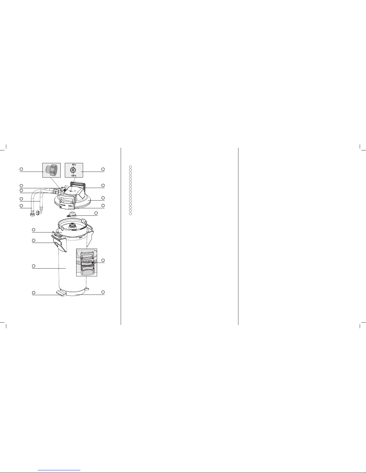
1 Begriffsübersicht
1
Druckbehälter
2
Filterkartusche
3
Druckbehälterdeckel
4
Anschlusskopf
5
Eingangsschlauch
6
Einga ngsventil am Eingangsschlauch
7
Ausgangssc hlauch zum Endgerät
8
Verschlusssicherung
9
Trit tla sch en
10
Auswerfersockel
11
Mantelgriffe
12
Transportschutzkappe
13
Verschnitteinstellschraube
14
Deckelgriff
15
Reduzierstück 1”– 3/4”
16
Spü lventil mit Spülschlauch
2 Allgemeine Informationen
2.1 Funktion und Anwendungsbereich
Die Hobart Wasserfi ltersysteme HYDROLINE STAR und HY DROLINE STAR Extra
optimieren Leitungswasser für Gläser-, Besteck- und Geschirrspülmaschinen durch
Teil- bzw. Vollentsalzung.
Durch Hobart HYDR OLINE STAR werden dem Leitungswasser im Durchfl uss ver fahren über einen Ionenaustauscher selektiv Calcium- und Magnesium -Ionen
entzogen. Karbonathärtebedingte Rückst ände beim Trocknen des Spülguts sowie
Kalkablagerungen an wichtigen Maschinenteilen werden verhinder t. Dadurch verlängert sich die Lebensdauer der Spülmaschinen entscheiden d.
Darüber hinaus gewährleistet Hobart HYD ROLINE STAR Extra durch Vollentsalzung
des Leitungswassers die Eliminierung aller im Wasser enthaltenen Salze, wodurch
deren Ablagerung an Gläsern und Bestecken verhindert wird .
2.2 Gewährle istungsbes timmungen
Die Filtersysteme HYDROLINE STAR und HY DROLINE STAR Extra unterliegen der
gesetzlichen Gewährleistung von zwei Jahren. Ein Gewährleistungsanspruch kann nur
geltend gemacht werden, wenn alle Hinweise dieser Anleitung befolgt und beachtet
werden.
2.3 Lagerun g / Transport
Umgebungsbedingungen bei Lager ung und Transport in den technischen Daten
(Kapitel 10) beachten.
Das Handbuch ist als Teil des Produkts zu verstehen und während der gesamten
Lebensdauer des Filtersystems aufzubewahren und an nachfolgende Besitzer weiterzugeben.
2

2.4 Recycling/Entsorgung
Durch die ordnungsgemäße Entsorgung dieses Produkts und seiner Verpackungsbestandteile tragen Sie dazu bei, potenzielle negative Auswirkungen auf Mensch und Umwelt zu
vermeiden, die durch die unsachgemäße Entsorgung auftreten könnten. Bitte führen Sie
die zu entsorgenden Einheiten gemäß den örtlichen Bestimmungen an den dafür vorgesehenen Sammelstellen einem geordneten Recycling zu.
Erschöpfte Filterkartuschen werden bei Anlieferung an die angegebenen Adressen
zurückgenommen.
3 Betriebs- und Sicherheitshinweise
3.1 Qualifi ziertes Personal
Installation und Instandhaltung des Filtersystems darf nur von geschultem und autorisiertem Personal vorgenommen werden.
3.2 Bestimmungsgemäßer Gebrauch
Der einwandfreie und sichere Betrieb des Produkts setzt die in diesem Handbuch
beschriebene Vorgehensweise für Installation, Gebrauch und Instandhaltung voraus.
Hinweis: Das Filtersystem sowie die systemspezifi schen Filterkartuschen HYDROLINE
STAR/STAR Extra dürfen nur vor Endgeräten wie Gläser-, Besteck- und Geschirrspül-
maschinen zum Einsatz kommen.
3.3 Haftungsausschluss
Die Installation muss genau nach den Angaben in diesem Handbuch ausgeführt werden.
Hobart haftet nicht für etwaige Schäden einschließlich Folgeschäden, die durch falsche
Installation oder falschen Gebrauch des Produkts entstehen können.
3.4 Spezifi sche Sicherheitshinweise
• Als Speisewasser für das Hobart Wasserfi ltersystem darf ausschließlich Trink wasser
innerhalb des in Kapitel 10 angegebenen Wassereingangstemperaturbereichs verwendet werden. Keinesfalls darf mikrobiologisch belastetes Wasser oder Wasser
unbekannter mikrobiologischer Qualität ohne angemessene Sterilisierung eingesetzt
werden.
• Das gefi lterte Wasser ist aus Geschmacksgründen für die Zubereitung von Speisen
und Getränken nicht geeignet.
• Im Fall einer Abkochaufforderung für das Leitungswasser von offi zieller Stelle ist das
Filtersystem außer Betrieb zu nehmen. Nach Ende der Abkochaufforderung müssen
die Filterkartusche getauscht sowie die Anschlüsse gereinigt werden.
• Hobart empfi ehlt, das Filtersystem nicht über einen längeren Zeitraum außer Betrieb
zu nehmen. Nach Stagnationszeiten von über 4 Wochen sollte eine Boilerspülung
oder ein Vorspülgang durchgeführt werden. Bitte beachten Sie hierzu auch die maximale Einsatzdauer der Filterkartusche von 12 Monaten (Kapitel 6).
• Das Filtersystem ist nicht beständig gegen stark konzentrierte Reinigungsmittel
(z. B. Bleichmittel, chlorierte Lösungsmittel, starke Oxidationsmittel) und darf nicht
damit in Kontakt kommen.
3
• Während des Betriebs darf das Filtersystem nicht geöffnet oder demontiert werden.
Die Filterkartusche darf nicht geöffnet werden.
• Druckbehälter und Druckbehälterdeckel des Filtersystems sind -bei sachgemäßer
Installation und Nutzung sowie bei Einhaltung der in den technischen Daten genannten Betriebsbedingungen- auf eine Lebensdauer von bis zu 10 Jahren ausgelegt (ab
Installationsdatum). Spätestens nach Ablauf von 10 Jahren muss in jedem Fall ein
Austausch erfolgen. Die Schläuche müssen turnusgemäß spätestens nach 5 Jahren
ausgewechselt werden.
•
Produktionsdatum:
Produktionscodeaufkleber Filterkartusche und Umkarton, Beispiel: B715002010
7 Produktionsjahr, hier: 2007
15 Produktionswoche, hier: Kalenderwoche 15
002 Chargen-Nr. Filtermedium, hier die mengenmäßig abgefüllte zweite Charge
010 laufende Nummer der Filterkartusche, hier die zehnte Kartusche aus der zweiten Charge
Produktionscodeaufkleber Anschlusskopf, Beispiel: 7102 XX
7 Produktionsjahr, hier: 2007
10 Produktionswoche, hier: Kalenderwoche 10
2 Produktionstag von Montag (1) bis Freitag (5), hier: Dienstag
XX Interne Kennziffer
Produktionsdatum Druckbehälter und Druckbehälterdeckel, Beispiel: 0307
03 Produktionsmonat, hier: März
07 Produktionsjahr, hier: 2007
3.5 Sicherheitstechnische Montagehinweise
• Das mit dem Filter betriebene Endgerät muss vor Installation kalkfrei sein.
!
Achtung: Vor dem Filtersystem darf keine Enthärtungsanlage betrieben werden.
• Filtersystem vor Sonneneinstrahlung und mechanischen Beschädigungen schützen.
Nicht in der Nähe von Hitzequellen und offenem Feuer montieren.
• Vor dem Eingangsschlauch des Filtersystems muss ein Absperrventil installiert sein.
• Ist der Wasserdruck größer als 6 bar, muss ein Druckminderer vor das Filtersystem
eingebaut werden.
• Am Wassereingang des Filterkopfs ist ein vom DVGW baumustergeprüfter Rückfl ussverhinderer werksseitig eingebaut.
• Zwischen Wasserfi lter und Verbraucher dürfen keine Kupferrohre und keine verzinkten oder vernickelten Rohre/Verbindungsstücke eingebaut sein. Hier wird der
Einsatz von Hobart Schlauchsets empfohlen. Bei der Werkstoffauswahl von wasserberührenden Teilen nach dem Hobart Filtersystem muss beachtet werden, dass
das entkarbonisierte bzw. vollentsalzte Wasser verfahrensbedingt freie Kohlensäure
enthält.
• Die Installation aller Teile ist entsprechend der länderspezifi schen Richtlinien zur
Installation von Trinkwassereinrichtungen durchzuführen.
4
4 Installation
!
Achtung: Vor Installation die technischen Daten (Kapitel 10) und die Betriebs- und
Sicherheitshinweise (Kapitel 3) beachten. Nach Lagerung unter 0 °C ist das Produkt
bei geöffneter Originalverpackung mindestens 24 Stunden vor Inbetriebnahme bei Umgebungstemperatur des Installationsorts zu lagern.
4.1 Lieferumfang
Nehmen Sie vor der Installation den gesamten Lieferumfang aus der Verpackung und
prüfen Sie diesen auf Vollständigkeit:
1x Druckbehälter
1
1x Druckbehälterdeckel
3
1x Filterkartusche 2, Hinweis: blaue Markierung an HYDROLINE STAR Filter kartusche,
rote Markierung an HYDROLINE STAR Extra Filterkartusche.
1x Handbuch
1x Karbonathärtetest bzw. Gesamthärtetest
1x Aufkleber für Service-Pass,
Hinweis: hellblauer Aufkleber für HYDROLINE STAR, roter
Aufkleber für HYDROLINE STAR Extra.
1x Reduzierstück 1”– 3/4”
1x Spülventil mit Spülschlauch
Sollten Teile des Lieferumfangs fehlen, wenden Sie sich bitte an die für Sie zuständige
Hobart Geschäftsstelle.
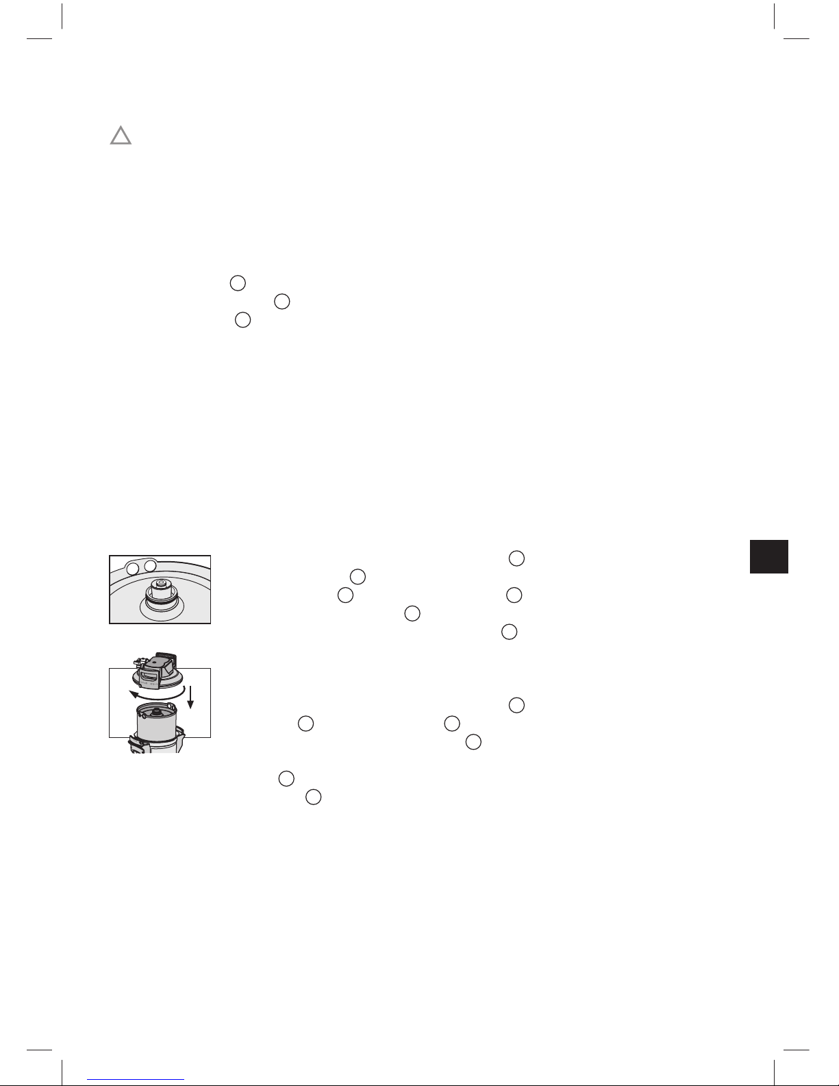
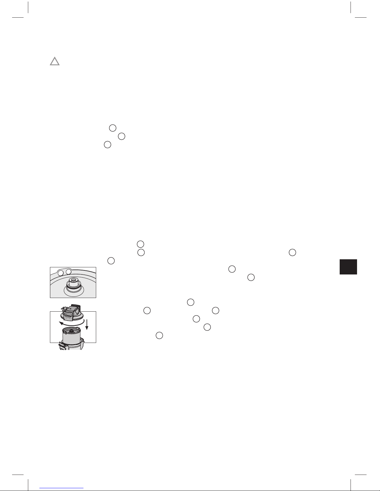
4.2 Montage des Druckbehälters und Druckbehälterdeckels
• Mit beiden Füßen auf die Trittlaschen 9 stellen.
• Druckbehälter
1
anheben und im Uhrzeigersinn drehen, bis
Mantelgriffe
11
über den Trittlaschen 9 stehen.
• Transportschutzkappe
12
von Filterkartusche entfernen.
• O-Ring-Dichtung der Filterkartusche
2
auf korrekten Sitz in Nut,
Verschmutzung und Beschädigung überprüfen.
Hinweis: Der Kartuschensitz ist werkseitig mit lebensmittelechtem
Schmiermittel gefettet.
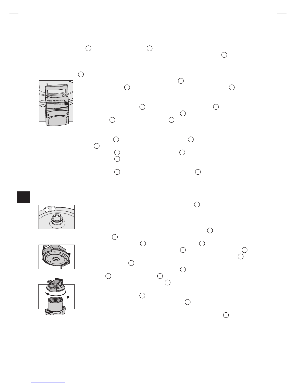
• Mit beiden Füßen auf die Trittlaschen
9
stellen und Druckbehälterdeckel 3 auf Druckbehälter 1 aufsetzen. Die Positionierung der
Pfeilmarkierung am Deckelgriff 14 muss dabei mit Nut „INSERT“
übereinstimmen.
• Druckbehälterdeckel 3 nach unten drücken und im Uhrzeigersinn bis zum Einrasten
der Verschlusssicherung 8 drehen.
5

4.3 Montage der Eingangs- und Ausgangsschläuche
Hinweis: Die Eingangs- und Ausgangsschläuche sind nicht im Standardlieferumfang ent-
halten. Die Verwendung von Hobart Schlauchsets wird empfohlen (Kapitel 11).
• Eingangsschlauch
5
am Eingang des Anschlusskopfs 4 und Ausgangsschlauch 7
am Ausgang des Anschlusskopfs
4
montieren.
Hinweis: Eingang „IN“ und Ausgang „OUT“ des Anschlusskopfs
4
sind mit O-Ringen als Dichtungen ausgestattet; deshalb dürfen hier keine zusätzlichen Flachdichtungen verwendet werden. Auf korrekten Sitz der O-Ringe achten.
!
Achtung: Das maximale Anzugsdrehmoment an den 1”- und 3/4”-Anschlüssen darf
15 Nm nicht überschreiten! Es dürfen nur Schlauchanschlüsse mit Flachdichtungen eingesetzt werden. Schläuche mit konischen Verschraubungen beschädigen die Anschlüsse
des Filterkopfs und führen zum Erlöschen des Gewährleistungsanspruchs!
Vor Montage Fließrichtung an der Oberseite des Filterkopfs beachten, IN = Wassereingang, OUT = Wasserausgang. Vor Installation Einbau abmessungen und Betriebslage
(Kapitel 10) beachten. Werden keine Originalschläuche verwendet, muss das mitgelieferte Reduzierstück 1”– 3/4”
15
verwendet werden, um eine korrekte Abdichtung des
Rückfl ussverhinderers zu gewährleisten.
5 Inbetriebnahme eines Neufi lters
5.1 Einstellung des Verschnitts
• Die Verschnitteinstellschraube
13
ist werkseitig auf 10% eingestellt und kann bei
Bedarf entsprechend der lokalen Wasserqualität oder der jeweiligen Anwendung auf
0% reduziert werden. Bei Fragen zur Wasserqualität berät Sie Ihr Lieferant oder Ihr
Ansprechpartner bei Hobart.
Hinweis: Für die Einstellung der Verschnitteinstellschraube
13
Inbusschlüssel 6 mm
bzw. 7/32” verwenden.
5.2 Bestimmung der Filterkapazität
• Bestimmung der lokalen Karbonathärte bzw. Gesamthärte mittels beiliegendem
Karbonathärte- bzw. Gesamthärtetest.
• Bestimmung der Filterkapazität mittels der Kapazitätstabellen (Kapitel 7) unter
Berücksichtigung der ermittelten Karbonat- bzw. Gesamthärte und des eingestellten
Verschnitts (Kapitel 5.1).
6
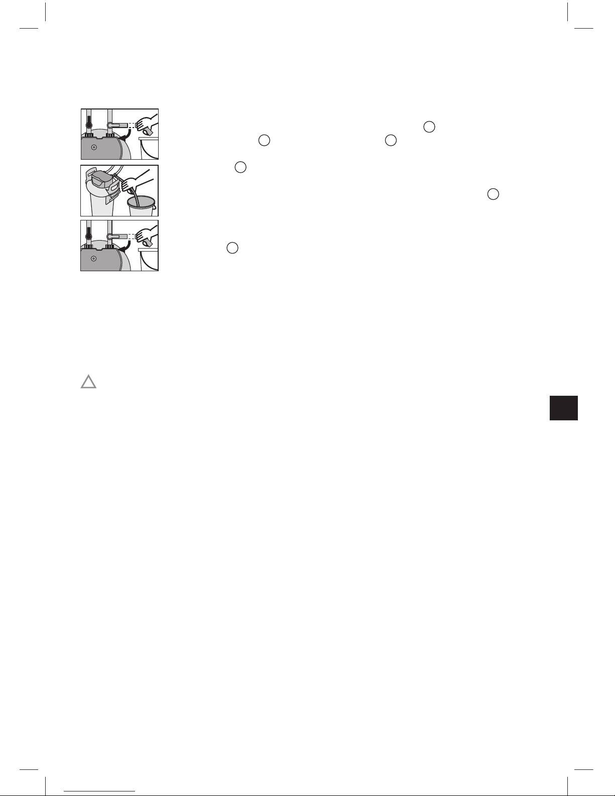
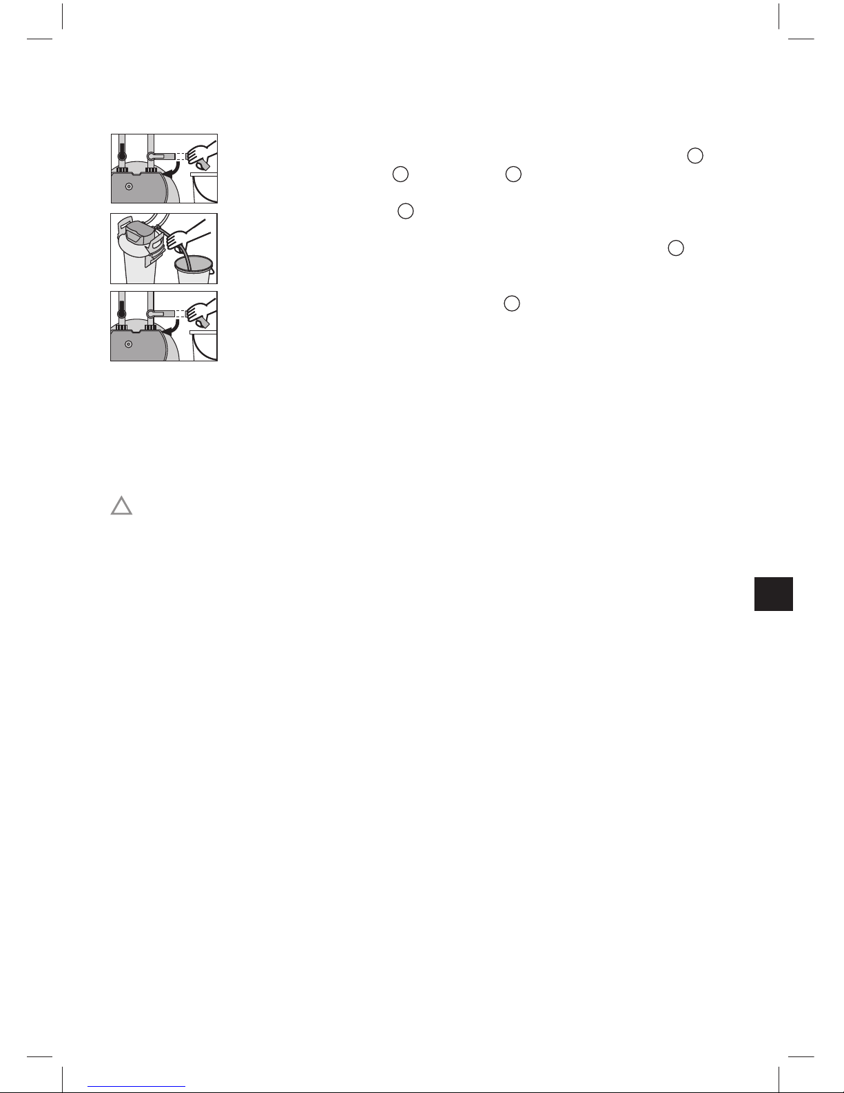
5.3 Einspülen und Entlüften der Filterkartusche
Hinweis: Zum Einspülen/Entlüften wird ein Eimer mit mindestens 10 Liter Fassungs-
vermögen benötigt.
• Eimer unter Spülschlauch stellen und Spülventil
16
öffnen.
• Eingangsventil
6
am Eingangsschlauch 5 öffnen, dabei
Spül schlauch im Eimer festhalten. Mit mindestens 10 Liter spülen.
• Spülventil 16 schließen und Eimer entleeren.
• System auf eventuelle Leckagen prüfen.
• Installationsdatum des Filtersystems auf dem Druckbehälter
1
und
nächstes Austauschdatum auf dem beiliegenden Aufkleber (HYDROLINE STAR: hellblauer Aufkleber, HYDROLINE STAR Extra: roter Aufkleber) vermerken und diesen auf dem Service-Pass auf dem Druckbehälter
1
anbringen.
6 Austausch der Filterkartusche
Der Austausch der Filterkartusche muss nach 6 bis 12 Monaten erfolgen, spätestens
12 Monate nach Inbetriebnahme, unabhängig vom Erschöpfungsgrad der Filterkartusche.
Ist die Kapazität der Filterkartusche bereits vorher erschöpft (Kapitel 7), muss der Austausch früher erfolgen.
!
Achtung: Beim Austausch alle demontierten Teile sorgfältig untersuchen! Defekte
Teile müssen ausgetauscht, verunreinigte Teile gereinigt werden! Vor Austausch die
Betriebs- und Sicherheitshinweise (Kapitel 3) beachten. Nach Lagerung unter 0 °C ist das
Produkt bei geöffneter Originalverpackung mindestens 24 Stunden vor Inbetriebnahme zu
lagern.
,
7
6.1 Entnehmen der Filterkartusche
• Spannungsversorgung des Endgeräts abschalten (Netzstecker ziehen).
• Eingangsventil 6 am Eingangsschlauch 5 schließen.
• Spül schlauch in einen Eimer stecken und durch Öffnen des Spülventils
16
Filter-
system drucklos machen. Die austretende Wassermenge in einem Eimer auffangen.
Hinweis: Wenn die austretende Wassermenge 1 Liter überschreitet, ist das Ein-
gangsventil 6 nicht komplett geschlossen oder verkalkt.
• Mit beiden Füßen auf die Trittlaschen 9 stellen und dabei den Druck-
behälterdeckel 3 durch Drücken der Verschlusssicherung 8 und
durch gleichzeitiges Drehen gegen den Uhrzeigersinn bis zum
Anschlag öffnen.
• Druckbehälterdeckel
3
vertikal auf den Deckelgriff 14 abstellen.
• Mit beiden Füßen auf die Trittlaschen
9
stellen und dabei Druckbehälter 1 an den Mantelgriffen 11 gegen den Uhrzeigersinn bis zum
Anschlag drehen.
• Füße von den Trittlaschen
9
nehmen und Druckbehälter 1 mit beiden Händen an
den Mantelgriffen
11
nach unten drücken.
• Erschöpfte Filterkartusche 2 aus dem Druckbehälter 1 entnehmen.
• Erschöpfte Filterkartusche
2
zum Entleeren mit Anschluss nach unten in Spüle
stellen (> 5 Min.).
• Erschöpfte Filterkartusche
2
mit der Transportschutzkappe 12 der neuen Filterkartusche verschließen und im Originalkarton an die von Ihrem Lieferant angegebene
Tausch-Adresse zurücksenden.
6.2 Einsetzen der Filterkartusche
• O-Ring-Dichtung der neuen Filterkartusche 2 auf korrekten Sitz in
Nut, Verschmutzung und Beschädigungen überprüfen.
Hinweis: Der Kartuschensitz ist werkseitig mit lebensmittelechtem
Schmiermittel gefettet.
• Anschlusssitz für den O-Ring der Filterkartusche 2 im Druckbehäl-
terdeckel 3 auf Schmutz und Beschädigungen überprüfen.
• Neue Filterkartusche 2 in den Druckbehälter 1 einsetzen.
• Mit beiden Füßen auf die Trittlaschen 9 stellen, Druckbehälter 1
anheben und dabei im Uhrzeigersinn drehen, bis Mantelgriffe
11
über
den Trittlaschen
9
stehen.
• Mit beiden Füßen auf die Trittlaschen 9 stellen und Druckbehälter-
deckel 3 auf Druckbehälter 1 aufsetzen. Die Positionierung der
Pfeilmarkierung am Deckelgriff 14 muss dabei mit Nut „INSERT“
übereinstimmen.
• Druckbehälterdeckel 3 nach unten drücken und im Uhrzeigersinn bis
zum Einrasten der Verschlusssicherung 8 drehen.
• Spannungsversorgung des Endgeräts einschalten (Netzstecker).
• Zum Einspülen und Entlüften der neuen Filterkartusche 2 Schritte
unter 5.3 durchführen.
8
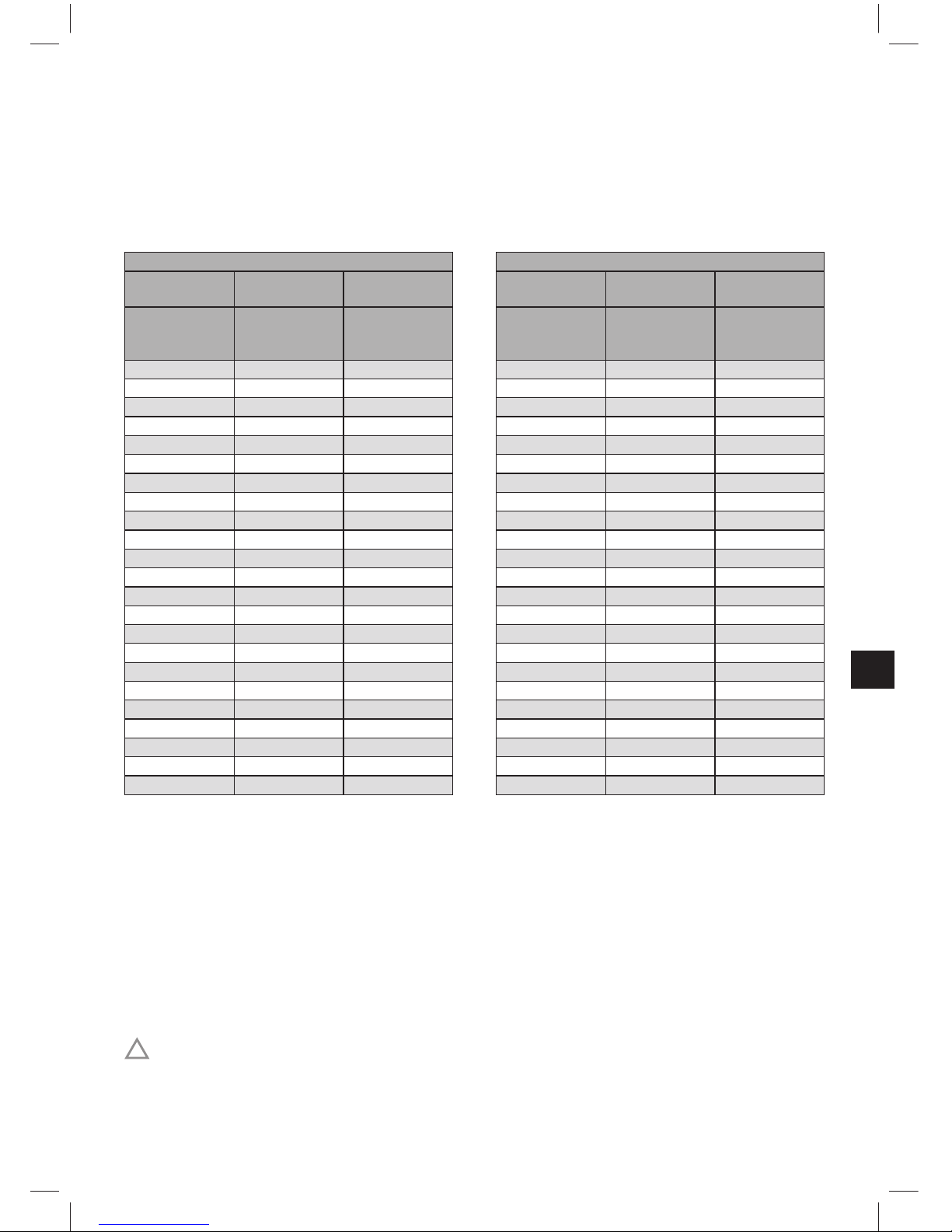
7 Filterkapazität
Zur Kontrolle des Erschöpfungsgrads der Filterkartusche wird die Programmierung
und Verwendung des entsprechenden Countdownzählers in der Steuerung der HobartSpülmaschine (siehe Bedienungsanleitung der Maschine) empfohlen.
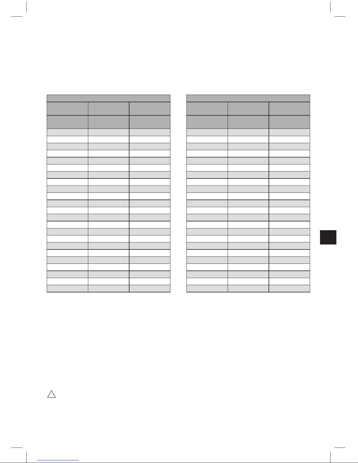
Kapazitätstabellen
HYDROLINE STAR HYDROLINE STAR Extra
Verschnitt-
einstellung 0%
Verschnitt-
einstellung 10%
Verschnitt-
einstellung 0%
Verschnitt-
einstellung 10%
Karbonathärte
in °KH
Volumen
in Liter
Volumen
in Liter
Gesamthärte
in °GH
Volumen
in Liter
Volumen
in Liter
4 30.000 32.667 4 12.500 13.611
5 24.000 26.133 5 10.000 10.889
6 20.000 21.778 6 8.333 9.074
7 17.143 18.667 7 7.143 7.778
8 15.000 16.333 8 6.250 6.806
9 13.333 14.519 9 5.556 6.049
10 12.000 13.067 10 5.000 5.444
11 10.909 11.879 11 4.545 4.949
12 10.000 10.889 12 4.167 4.537
13 9.231 10.051 13 3.846 4.188
14 8.571 9.333 14 3.571 3.889
15 8.000 8.711 15 3.333 3.630
16 7.500 7.167 16 3.125 3.403
17 7.059 7.686 17 2.941 3.203
18 6.667 7.259 18 2.778 3.025
19 6.316 6.788 19 2.632 2.865
20 6.000 6.533 20 2.500 2.722
21 5.714 6.222 21 2.381 2.593
23 5.217 5.681 23 2.174 2.367
25 4.800 5.227 25 2.000 2.178
28 4.286 4.667 28 1.786 1.944
31 3.871 4.215 31 1.613 1.756
35 3.429 3.733 35 1.429 1.556
Hinweis: Die angegebenen Kapazitäten sind Richtwerte, die je nach Produktvolumen-
strom, lokaler Wasserqualität und Maschinentyp um ± 20% variieren können.
8 Instandhaltung
Prüfen Sie das Filtersystem regelmäßig auf Leckagen. Prüfen Sie die Schläuche regelmäßig auf Knickstellen. Geknickte Schläuche müssen ersetzt werden.
Das komplette Filtersystem muss turnusgemäß nach spätestens 10 Jahren ausgewechselt werden.
Die Schläuche müssen turnusgemäß spätestens nach 5 Jahren ausgewechselt werden.
!
Achtung: Vor Auswechslung die technischen Daten (Kapitel 10) und die Betriebs- und
Sicherheitshinweise (Kapitel 3) beachten.
9

Reinigen Sie das Filtersystem außen regelmäßig mit einem weichen, feuchten Tuch.
!
Achtung: Verwenden Sie dabei keine materialunverträglichen Stoffe (Kapitel 3.4) oder
scharfe, scheuernde Reinigungsmittel.
9 Fehlerbehebung
9.1 Kein Wasserfl uss
Ursache: Wasserzufuhr geschlossen.
Fehlerbehebung: Wasserzufuhr am vorgeschalteten Absperrventil oder Eingangsventil
6
am Eingangsschlauch 5 öffnen.
!
Achtung: Die nachfolgenden Fehler dürfen nur von geschultem und autorisiertem
Personal behoben werden.
9.2 Kein oder geringer Wasserfl uss trotz geöffneter Wasserzufuhr
Ursache: Leitungsdruck zu gering.
Fehlerbehebung: Leitungsdruck überprüfen.
Falls der Fehler trotz ausreichendem Leitungsdruck weiterhin auftritt,
Filtersystem und Filterkartusche überprüfen und ggf. auswechseln.
!
Achtung: Vor Auswechslung die technischen Daten (Kapitel 10) und
die Betriebs- und Sicherheitshinweise (Kapitel 3) beachten.
9.3 Leckage an Verschraubungen
Ursache: Verschraubungen nicht ordnungsgemäß montiert.
Fehlerbehebung: Leitungsdruck überprüfen. Sämtliche Verschraubungen überprüfen und
gemäß Kapitel 4 montieren.
Falls der Fehler weiterhin auftritt, Filtersystem auswechseln.
!
Achtung: Vor Auswechslung die technischen Daten (Kapitel 10) und
die Betriebs- und Sicherheitshinweise (Kapitel 3) beachten.
9.4 Leckage nach Filtertausch
Ursache: O-Ring an Filterkartusche sitzt nicht korrekt.
Fehlerbehebung: Korrekten Sitz des O-Rings überprüfen (Kapitel 6.2).
!
Achtung: Vor Demontage die technischen Daten (Kapitel 10) und
die Betriebs- und Sicherheitshinweise (Kapitel 3) beachten.
10
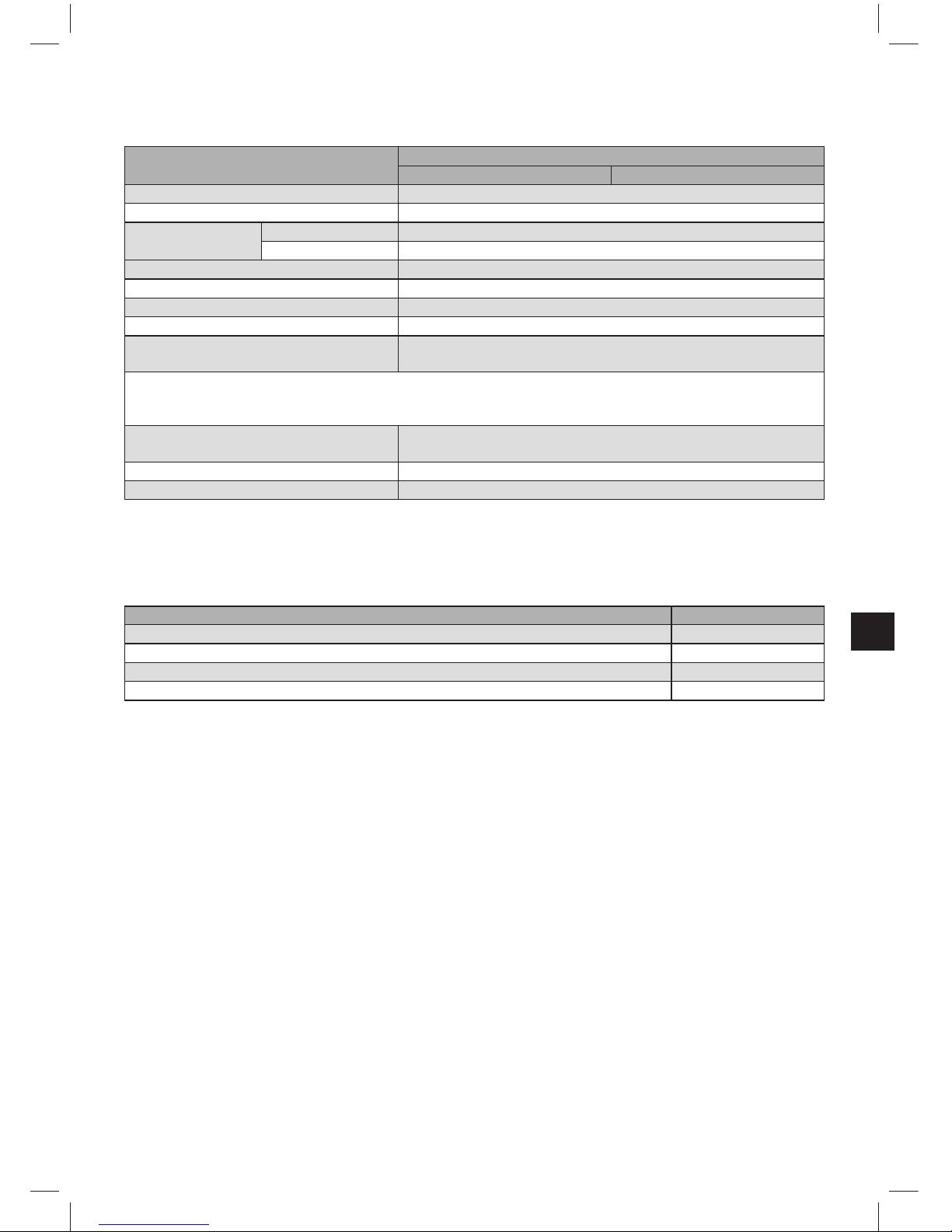
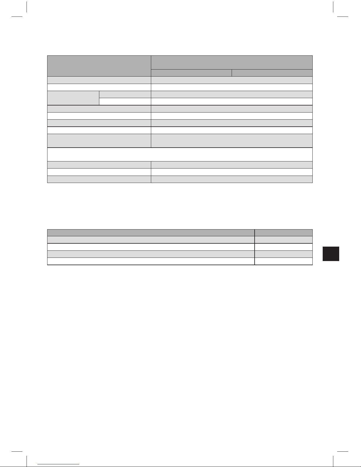
10 Technische Daten
Filtersystem HYDROLINE STAR/STAR Extra mit Filterkartusche
HYDROLINE STAR HYDROLINE STAR Extra
Betriebsdruck 2 bar – max. 6 bar
Betriebs-/Wassertemperatur 4°C – 60°C
Umgebungstemperatur bei
Betrieb 10°C – 60°C
Lagerung/Transport –20°C to 60°C
Durchfl uss bei 1 bar Druckverlust 850 l/h
Nenndurchfl uss gemäß Norm 300 l/h
Druckverlust bei Nenndurchfl uss 0,45 bar
Gewicht (trocken/nass) 18 kg/24 kg
Abmessungen Komplettsystem
(Breite/Tiefe/Höhe)
288 mm/255 mm/550 mm
Die Biegeradien des Eingangs- und Ausgangsschlauchs 2 m, DN13, 3/4"–3/4" betragen 130 mm und sind je
nach räumlicher Einbauorientierung und Betriebslage zusätzlich zu den Abmessungen des Komplettsystems zu
berücksichtigen.
Betriebslage Das Filtersystem kann wahlweise stehend oder liegend betrieben
werden.
Eingangsanschluss G 1"
Ausgangsanschluss G 3/4"
11 Bestellnummern
Filtersystem HYDROLINE STAR/HYDROLINE STAR Extra
Artikel Artikel-Nummer
HYDROLINE STAR (Komplettsystem mit Filterkartusche) 895440-1
HYDROLINE STAR Extra (Komplettsystem mit Filterkartusche) 895440-2
HYDROLINE STAR Wechselkartusche 895440-3
HYDROLINE STAR Extra Wechselkartusche 895440-4
11

1 Defi nition of Terms
1
Pressure Vessel
2
Filter Cartridge
3
Pressure Vessel Lid
4
Connector Head
5
Inlet Hose
6
Inlet Valve on the Inlet Hose
7
Outlet Hose to the Terminal Equipment
8
Locking
9
Kick Loop
10
Ejector Base
11
Mantle Handle
12
Transport Protective Cap
13
Bypass Setting Screw
14
Lid Handle
15
Reducer 1”– 3/4”
16
Flush valve with fl ush hose
2 General Information
2.1 Function and Application
The Hobart HYDROLINE STAR and HYDROLINE STAR Extra Water Filter Systems optimise tap water for dishwashers for glasses, cutlery and crockery by means of partial or
full demineralisation.
In the Hobart HYDROLINE STAR calcium and magnesium ions are selectively removed
from the drinking water via an ion exchanger using the fl ow method. This prevents residues on the dishes during drying due to carbonate hardness and scale deposits on important machine parts. This means that the dishwashers have a greatly increased service life.
Furthermore, Hobart HYDROLINE STAR Extra guarantees elimination of all salts in the
water by means of full demineralisation of the tap water, preventing them from being
deposited on glasses and cutlery.
2.2 Guarantee Provisions
The HYDROLINE STAR and HYDROLINE STAR Extra fi lter systems are subject to the
statutory guarantee of 2 years. A guarantee claim may be asserted only if all instructions
in this Handbook are followed and observed.
2.3 Storage/Transport
Adhere to the ambient conditions in the Technical Data (Chapter10) for storage and transport.
The handbook should be seen as part of the product and kept for the whole service life of
the fi lter system and passed on to subsequent owners.
12

2.4 Recycling/Disposal
By disposing of this product and its packaging in the correct manner you are helping to
prevent potential negative impacts on people and the environment that could be caused
by incorrect disposal. Comply with local regulations and bring the units to be disposed of
to a proper recycling facility at the collection points provided.
Used fi lter cartridges can be returned to the addresses listed.
3 Operating and Safety Information
3.1 Qualifi ed Personnel
Installation and maintenance of the fi lter system may be carried out only by trained or
authorised personnel.
3.2 Correct Use
The product can only be operated properly and safely if it is installed, used and serviced in
the manner described in this Manual. Use only cartridges suitable for this appliance.
Note: the HYDROLINE STAR/STAR Extra fi lter system and system-specifi c fi lter car-
tridges may only be used upstream from compatible end devices such as dishwashers for
glasses, cutlery and crockery.
3.3 Liability Exclusion
Installation must be carried out in accordance withthe instructions in this Manual. Hobart
shall not be held liable for any damage, including subsequent damage, arising from the
incorrect installation or use of the product.
3.4 Specifi c Safety Information
• Only drinking water within the intake water temperature range listed in Chapter 10
may be used as intake water for the Hobart water fi lter system. No microbiologically
impaired water or water of unknown microbiological quality may be used without
appropriate sterilisation.
• For reasons of fl avour, the fi ltered water is not suitable for the preparation of food and
drinks.
• If there is an offi cial requirement of boil tap water, decommission the fi lter system.
When the requirement to boil water comes to an end, the fi lter cartridge must be
replaced and the connections cleaned.
• Hobart recommends that the fi lter system shall not be decommissioned for a long
period. After stagnation times of over 4 weeks, the boiler should be fl ushed or a prerinse executed. Please also note the maximum usage period of the fi lter cartridge is
12 months (Chapter 6).
• The fi lter system is not resistant to heavily concentrated cleaning agents (e.g. bleach,
chlorinated solvents, heavy oxidants) and must not come into contact with them.
13
• The fi lter system must not be opened or dismantled during operation. The fi lter
cartridge must not be opened.
• The pressure vessel and the pressure vessel lid of the fi lter systems have a service
life of up to ten years (from the date of installation), provided that they are installed
and used correctly and the operating conditions outlined in the Technical Data chapter
are adhered to. They must always be replaced after a maximum of ten years. The
hoses must be replaced in rotation after a maximum of fi ve years.
• Production date:
Production code sticker fi lter cartridge and packaging - Example: B715002010
7 Production year, here: 2007
15 Production week, here: calendar week 15
002 Batch No. fi lter medium, here the second batch fi lled in terms of quantity
010 Serial number of the fi lter cartridge, here the tenth cartridge from the second batch
Production code sticker connector head - Example: 7102 XX
7 Production year, here: 2007
10 Production week, here: calendar week 10
2 Production day from Monday (1) to Friday (5), here: Tuesday
xx Internal code
Production date pressure vessel and pressure vessel lid - Example: 0307
03 Production month, here: March
07 Production year, here: 2007
3.5 Technical Safety Assembly Instructions
• The terminal device operated with the fi lter must be free of limescale prior to
installation.
!
Caution: No water softening system may be operated upstream from
the fi lter system.
• Protect the fi lter system from sunlight and mechanical damage. Do not assemble
near sources of heat and open fl ames.
• A stop valve must be installed before the fi lter system intake hose.
• If the water pressure is higher than 6 bar, a pressure reducer must be installed before
the fi lter system.
• A non-return valve tested by the DVGW has been factory-installed at the water intake
of the fi lter head.
• No copper pipes and no galvanised or nickel-plated pipes/connectors may be
installed between the water fi lter and the consumer. The use of Hobart hose sets
is recommended here. When choosing the material for parts that come into contact
with water after the Hobart fi lter system it must be remembered that, due to the
process, decarbonised and/or fully demineralised water contains free carbon dioxide.
• All parts must be installed in accordance with the country-specifi c guidelines on the
installation of drinking water facilities.
14
4 Installation
!
Caution: Prior to installation read the technical data (Chapter 10) and the operating
and safety information (Chapter 3). After the product has been stored at temperatures
below 0°C, it must be stored (with the original packaging open) at the ambient
temperature of the place of installation for at least 24 hours before use.
4.1 Scope of Delivery
Prior to installation, remove the entire delivery scope from the packaging and check that
everything is there:
1x pressure vessel
1
1x pressure vessel lid
3
1x fi lter cartridge 2, Note: Blue marking on HYDROLINE STAR fi lter cartridge, Red
marking on HYDROLINE STAR Extra fi lter cartridge.
1x manual
1x carbonate hardness test or total hardness test
1x sticker for Service Pass, Note: Light blue sticker for HYDROLINE STAR, red sticker for
HYDROLINE STAR Extra.
1x reducer 1”– 3/4”
1x flush valve with flush hose
If parts of the delivery scope are missing, please contact your local Hobart offi ce.
4.2 Assembly of the pressure vessel and the pressure vessel lid
• Stand on the kick loops
9
with both feet.
• Lift the pressure vessel 1 and turn it clockwise until the mantle handles 11 are over
the kick loops
9
.
• Remove the transport protective cap
12
from the fi lter cartridge.
• Check the O-ring seal of the fi lter cartridge
2
for correct seat in the
groove, dirt and damage. Note: The cartridge seat has been
lubricated with food-safe lubricant at the factory.
• Stand on the kick loops 9 with both feet and place the pressure
vessel lid
3
on the pressure lid 1. The positioning of the arrow
marking on the lid handle 14 must line up with the “INSERT” groove.
• Press the pressure vessel lid 3 down and turn clockwise until the
lock engages 8.
15

4.3 Assembly of inlet and outlet hoses
Note: The inlet and outlet hoses are not included in the standard scope of delivery. The
use of Hobart hose sets is recommended (Chapter 11).
• Fit inlet hose
5
at the inlet of the connector head 4 and outlet hose 7 at the outlet
of the connector head
4
.
Note: Inlet “IN” and outlet “OUT” of the connector head 4 are equipped with
O-rings as seals, therefore no additional fl at seals may be used here. Make sure that
the O-rings are seated correctly.
!
Caution: The max. tightening torque at the 1“ and 3/4“ connections must not exceed
15Nm! Only hose connections with fl at seals may be used. Hoses with conical screw
connections damage the connections of the fi lter head and invalidate any guarantee
claims! Before assembly, note the direction of fl ow on the upper side of the fi lter head,
IN = water inlet, OUT = water outlet. Prior to installation, note installation dimensions
and operating position (Chapter 10). If no original hoses are used, the 1“- 3/4“
15
reducer
supplied must be used to ensure correct sealing of the return valve.
5 Commissioning a New Filter
5.1 Setting the Bypass
• The bypass setting screw
13
has been set to 10% at the factory and, if necessary,
can be decreased to 0% according to the local water quality or application in question. If you have any questions about water quality, your supplier or your contact at
Hobart will advise you.
Note: Use Allen key 6mm or 7/32“ to adjust the bypass setting screw
13
.
5.2 Identifying the Filter Capacity
• Identify the local carbonate hardness or total hardness using the enclosed carbonate
hardness or total hardness test kit.
• Identify the fi lter capacity using the capacity tables (Chapter 7) taking account of the
carbonate or total hardness identifi ed and the bypass setting (Chapter 5.1).
16
5.3 Flushing and Bleeding the Filter Cartridge
Note: A bucket with a minimum capacity of 10L is needed for fl ushing/bleeding.
• Place the bucket under the fl ush hose and open the fl ush valve
16
.
• Open the inlet valve 6 on inlet hose 5 while holding the fl ush hose
in the bucket. Flush with at least 10 litres.
• Close the fl ush valve
16
and empty the bucket.
• Check system for any leaks.
• Note installation date of the fi lter system on pressure vessel 1 and
next exchange date on the enclosed sticker (HYDROLINE STAR: light
blue sticker, HYDROLINE STAR Extra: red sticker) and attach it to the
Service Pass on the pressure vessel
1
.
6 Exchanging the Filter Cartridge
The fi lter cartridge must be replaced after 6–12 months, at the latest 12 months after
commissioning, irrespective of the level of exhaustion of the fi lter system. If the capacity
of the fi lter cartridge has been exhausted (Chapter 7), it must be replaced earlier.
!
Caution: During the exchange, carefully examine all dismantled parts! Faulty parts
must be exchanged, dirty parts cleaned! Read the operating and safety information
(Chapter 3) prior to replacement. After the product has been stored at temperatures
below 0°C, it must be stored with the original packaging open at the ambient temperature
of the place of installation for at least 24 hours before entering use.
,
17
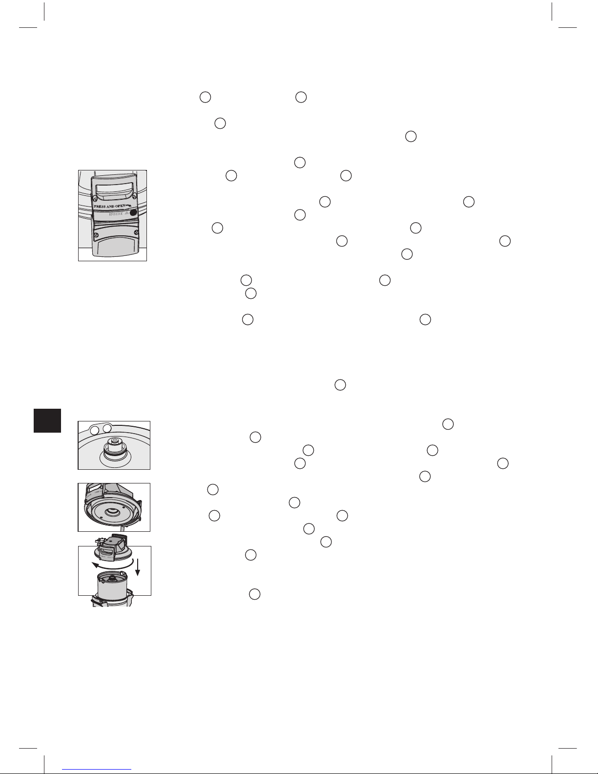
6.1 Removing the Filter Cartridge
• Switch off the power supply of the terminal equipment (remove plug).
• Close the inlet valve 6 at the inlet hose 5.
• Place the fl ush hose in a bucket and remove pressure from the fi lter system by
opening the fl ush valve
16
. Collect waste water in the 10L bucket.
Note: If the escaping water is more than 1 litre, the inlet value
6
is not completely
closed or is blocked with scale.
• Stand on the kick loops 9 with both feet while opening the pressure
vessel lid 3 by pressing the lock 8 and turning it anti-clockwise as
far as it will go.
• Place the pressure vessel lid 3 vertically on the lid handle 14.
• Stand on the kick loops
9
with both feet while turning the pressure
vessel
1
anti-clockwise by the mantle handles 11 as far as it will go.
• Take your feet off the kick loops 9 and press the pressure vessel 1
down with both hands on the mantle handles
11
.
• Remove used fi lter cartridge 2 from the pressure vessel 1.
• Place the used fi lter cartridge
2
in the sink with the connection facing down for
drainage (> 5 min).
• Lock the used fi lter cartridge
2
with the transport protection cap 12 of the new fi lter
cartridge and return in the original packaging to the appropriate address as listed by
your supplier.
6.2 Inserting the Filter Cartridge
• Check the O-ring seal of the new fi lter cartridge 2 for correct seat in the groove, dirt
and damage. Note: The cartridge seat has been lubricated with food-safe lubricant at
the factory.
• Check the connector seat of the fi lter cartridge O-ring
2
in the pres-
sure vessel lid 3 for dirt and damage.
• Place new fi lter cartridge
2
in the pressure vessel 1.
• Stand on the kick loops
9
with both feet; lift the pressure vessel 1
whole turning clockwise until the mantle handles 11 are over the kick
loops 9.
• Stand on the kick loop 9 with both feet and place the pressure ves-
sel lid
3
on the pressure vessel 1. The positioning of the arrow
marking on the lid handle
14
must line up with the “INSERT” groove.
• Press the pressure vessel lid 3 down and turn clockwise until the
lock engages 8.
• Switch on electrical power supply to the terminal device.
• Execute the steps described under 5.3 to fl ush and bleed the new
fi lter cartridge 2.
18
7 Filter Capacity
For the precise, continuous control of the degree of fi lter cartridge exhaustion, it is
recommended to program and use the count down counter of the control of the Hobart
dishwasher (refer to the user manual of the machine)
Capacity Tables
HYDROLINE STAR HYDROLINE STAR Extra
Bypass setting
0 %
Bypass setting
10 %
Bypass setting
0 %
Bypass setting
10 %
Carbonate
hardness in
°KH
Volume
in litres
Volume
in litres
Tota l h ard ness
in °GH
Volume
in litres
Volume
in litres
4 30.000 32.667 4 12.500 13.611
5 24.000 26.133 5 10.000 10.889
6 20.000 21.778 6 8.333 9.074
7 17.143 18.667 7 7.143 7.778
8 15.000 16.333 8 6.250 6.806
9 13.333 14.519 9 5.556 6.049
10 12.000 13.067 10 5.000 5.444
11 10.909 11.879 11 4.545 4.949
12 10.000 10.889 12 4.167 4.537
13 9.231 10.051 13 3.846 4.188
14 8.571 9.333 14 3.571 3.889
15 8.000 8.711 15 3.333 3.630
16 7.500 7.167 16 3.125 3.403
17 7.059 7.686 17 2.941 3.203
18 6.667 7.259 18 2.778 3.025
19 6.316 6.788 19 2.632 2.865
20 6.000 6.533 20 2.500 2.722
21 5.714 6.222 21 2.381 2.593
23 5.217 5.681 23 2.174 2.367
25 4.800 5.227 25 2.000 2.178
28 4.286 4.667 28 1.786 1.944
31 3.871 4.215 31 1.613 1.756
35 3.429 3.733 35 1.429 1.556
Note: The stated capacities are guide values that may vary by ± 20% depending on the
product volume fl ow, local water quality and machine type.
8 Repair
Regularly check the fi lter system for leaks. Regularly check the hoses for kinks. Bent
hoses must be replaced.
The complete fi lter system must be replaced in rotation after a maximum of ten years.
The hoses must be replaced in rotation after a maximum of fi ve years.
!
Caution: Prior to exchange read the technical data (Chapter 10) and the operating and
safety information (Chapter 3).
19

Regularly clean the outside of the fi lter system with a soft, damp cloth.
!
Caution: Do not use any substances incompatible with the material (Chapter 3.4) or
astringent, abrasive cleaning agents.
9 Troubleshooting
9.1 No water fl ow
Cause: Water intake closed.
Troubleshooting: Open water intake on the upstream stop valve or inlet valve
6
on inlet
hose 5.
!
Caution: The following faults may be remedied only by trained and authorised
personnel.
9.2 No or low water fl ow in spite of open water intake
Cause: Mains pressure too low.
Troubleshooting: Check mains pressure.
If the fault continues to occur in spite of adequate mains pressure,
check the fi lter system and fi lter cartridge and change if necessary.
!
Caution: Prior to exchange read the technical data (Chapter 10) and
the operating and safety information (Chapter 3).
9.3 Leaking screw connections
Cause: Screwed connections not fi tted correctly.
Troubleshooting: Check mains pressure. Check all screwed connections and mount
according to Chapter 4.
If the fault continues, exchange fi lter system.
!
Caution: Prior to exchange read the technical data (Chapter 10) and
the operating and safety information (Chapter 3).
9.4 Leak continues after fi lter has been replaced
Cause: O-ring on fi lter cartridge not sitting correctly.
Troubleshooting: Check correct seat of the O-ring (Chapter 6.2).
!
Caution: Prior to dismantling read the data (Chapter 10) and the
operating and safety information (Chapter 3).
20
10 Technical Data
Filter system HYDROLINE STAR/STAR Extra
with fi lter cartridge
HYDROLINE STAR HYDROLINE STAR Extra
Operating pressure 2 bar – max. 6 bar
Operating/water temperature 4°C – 60°C
Ambient temperature during
operation 10°C – 60°C
storage/transport –20°C to 60°C
Flow rate with 1 bar pressure loss 850 l/h
Nominal fl ow according to Norm 300 l/h
Pressure loss at nominal fl ow 0,45 bar
Weight (dry/wet) 18 kg/24 kg
Dimensions complete system
(Width/Depth/Height)
288 mm/255 mm/550 mm
The bending radii of the inlet and outlet hose 2m, DN13, 3/4"–3/4" are 130mm and, depending on the installation
orientation and operating space, must be considered in addition to the dimensions of the complete system.
Operating position The fi lter system can be operated either vertically or horizontally.
Inlet connection G 1"
Outlet connection G 3/4"
11 Order Numbers
Hobart HYDROLINE STAR/HYDROLINE STAR Extra
Article Article Number
HYDROLINE STAR (complete system with fi lter cartridge) 895440-1
HYDROLINE STAR Extra (complete system with fi lter cartridge) 895440-2
HYDROLINE STAR replacement cartridge 895440-3
HYDROLINE STAR Extra replacement cartridge 895440-4
21

1 Eléments
1
Chambre de pression
2
Cartouche fi ltrante
3
Couvercle de chambre de pression
4
Tête de raccordement
5
Flexible d‘entrée
6
Vanne d‘entrée sur le fl exible d‘entrée
7
Flexible de sortie pour appareil
8
Verrou de sécurité
9
Appuis-pieds
10
Support d‘éjection
11
Poignées
12
Capuchon de protection
13
Vis by-pass
14
Poignée de couvercle
15
Réducteur 1” – 3/4”
16
Valve de rinçage avec flexible de rinçage
2 Généralités
2.1 Fonction et domaine d’application
Les systèmes de fi ltration Hobart HYDROLINE STAR et HYDROLINE STAR Extra
optimisent l’eau du robinet utilisée pour les lave-vaisselle grâce à une déminéralisation
partielle ou totale.
De façon sélective, par l’intermédiaire d’une résine échangeuse d’ions, Hobart
HYDROLINE STAR retire des ions calcium et magnésium lorsque l’eau traverse le
fi ltre. Ce système empêche ainsi le dépôt de résidus liés à la dureté carbonate lors du
séchage de la vaisselle de même qu’un entartrage de pièces de machine importantes,
ce qui se traduit par un allongement considérable de la durée de vie des machines.
Le modèle Hobart HYDROLINE STAR Extra garantit quant à lui, au moyen d’une
déminéralisation totale de l’eau du robinet, l’élimination de tous les sels contenus
dans l’eau afi n d’éviter des dépôts sur les verres et les couverts.
2.2 Dispositions relatives à la garantie
Les systèmes de fi ltration HYDROLINE STAR et HYDROLINE STAR Extra sont assortis d’une garantie légale de 2 ans. Un recours en garantie ne pourra être invoqué que si
toutes les instructions du présent manuel ont été lues et respectées.
2.3 Stockage/Transport
Lors du stockage et du transport, respecter les conditions indiquées dans les
caractéristiques techniques (chapitre 10).
Le manuel fait partie intégrante du produit. Il doit être conservé durant toute la durée
de vie du système de fi ltration et, le cas échéant, devra être transmis au prochain
utilisateur.
22

2.4 Recyclage/Mise au rebut
En éliminant ce produit et les parties de l’emballage conformément aux prescriptions,
vous contribuez à éviter les répercussions négatives sur les êtres humains et l’environnement qu’une mise au rebut non conforme peut avoir. Veuillez déposer, en
vue d’un recyclage approprié, les produits à éliminer aux points de collecte prévus à cet
effet conformément aux prescriptions locales.
Les cartouches fi ltrantes saturées renvoyées aux adresses mentionées seront recyclées.
3 Consignes d’utilisation et de sécurité
3.1 Personnel qualifi é
L’installation et l’entretien du système de fi ltration sont réservés à un personnel formé et
autorisé.
3.2 Utilisation conforme
Le fonctionnement correct et sûr du produit implique le respect des consignes d’installation, d’emploi et d’entretien fournies dans le présent manuel.
Remarque : le système de fi ltration et les cartouches fi ltrantes spécifi ques HYDROLINE
STAR/STAR Extra se montent uniquement sur les lave-vaisselle.
3.3 Exclusion de responsabilité
L’installation doit rigoureusement s’effectuer selon les indications du présent manuel. La
société Hobart ne saurait être tenue pour responsable d’éventuels dommages directs ou
indirects résultant d’une installation incorrecte ou d’une utilisation non conforme du produit.
3.4 Consignes de sécurité spécifi ques
• Le système de fi ltration Hobart ne peut être alimenté qu’avec de l’eau potable dans la
plage de température d’entrée indiquée au chapitre 10. N’utiliser en aucun cas de
l’eau chargée de contaminants microbiologiques ou de l’eau dont la qualité microbiologique est inconnue sans effectuer de stérilisation appropriée.
• Pour des raisons de goût, l’eau fi ltrée ne convient pas à la préparation d’aliments ou
de boissons.
• Si un service offi ciel recommandait de faire bouillir l’eau du robinet, le système de
fi ltration devrait être mis hors service. A la levée de cette instruction, il est nécessaire
de changer la cartouche fi ltrante et de nettoyer les raccords.
• Hobart conseille de ne pas mettre le système hors service pendant un intervalle
de temps prolongé. Après une période de stagnation de plus de 4 semaines, il est
recommandé de rincer le chauffe-eau ou d’opérer un pré-rinçage. Tenir à cet effet
aussi compte de la durée d’utilisation maximale de la cartouche fi ltrante, soit 12 mois
(chapitre 6).
• Le système de fi ltration ne résiste pas à des détergents à forte concentration (par ex.
agents de blanchiment, solvants chlorés, oxydants forts) et ne doit pas entrer en
contact avec de tels produits.
23

• Il est interdit d’ouvrir ou de démonter le système de fi ltration pendant le fonctionnement. Il est également proscrit d’ouvrir la cartouche fi ltrante.
• La chambre de pression et son couvercle, qui font partie du système de fi ltration,
sont conçus, si l‘appareil a été correctement installé et utilisé et si les conditions d‘utilisation indiquées dans les caractéristiques techniques ont été respectées, pour une
durée de vie pouvant aller jusqu‘à 10 ans (à compter de la date d‘installation). Après
cette période de 10 ans, au plus tard, un remplacement est absolument nécessaire.
Les fl exibles doivent être remplacés au plus tard tous les 5 ans.
•
Date de fabrication:
Etiquette avec code de fabrication de la cartouche fi ltrante et de l’emballage - exemple :
B715002010
7 Année de fabrication, ici : 2007
15 Semaine de fabrication, ici : semaine 15
002 N° de lot matière fi ltrante, ici le deuxième lot rempli quantitativement
010 Numéro de la cartouche fi ltrante, ici la dixième cartouche du deuxième lot
Etiquette avec code de fabrication de la tête de raccordement - exemple : 7102 XX
7 Année de fabrication, ici : 2007
10 Semaine de fabrication, ici : semaine 10
2 Jour de fabrication, lundi (1) à vendredi (5), ici : mardi
XX Code interne
Date de fabrication de la chambre de pression et de son couvercle – exemple : 0307
03 Mois de fabrication, ici : mars
07 Année de fabrication, ici : 2007
3.5 Consignes de montage relatives à la sécurité
• L’appareil raccordé avec le fi ltre doit être dépourvu de tartre avant l’installation du
système.
!
Attention : Il est interdit d’utiliser un adoucisseur à sel en amont du
système de fi ltration Hobart.
• Conserver le système de fi ltration à l’abri de rayons solaires et le protéger contre des
dommages mécaniques.
• Ne pas le monter à proximité de sources de chaleur ou de fl ammes nues.
• Une vanne d’arrêt doit être installée en amont du fl exible d‘entrée du système de
fi ltration.
• Si la pression de l‘eau est supérieure à 6 bars, un réducteur de pression doit être
monté en amont du système de fi ltration.
• Un clapet anti-retour assorti d’une homologation de modèle établie par l’association
allemande technique et scientifi que des métiers de l’eau et du gaz (DVGW) est monté
en usine au niveau de l‘arrivée d‘eau.
• Aucun tuyau en cuivre et aucun tuyau/raccord zingué ou nickelé ne doivent être
montés entre le fi ltre à eau et le consommateur. Il est recommandé d’utiliser à
cet effet les kits de fl exibles Hobart. Lors de la sélection du matériau des pièces
qui entrent en contact avec l’eau en aval du système de fi ltration Hobart, il faut se
rappeler que l’eau décarbonatée ou complètement déminéralisée contient, du fait
du principe de traitement, de l’acide carbonique à l’état libre.
• L’installation de toutes les pièces doit s’exécuter conformément aux directives
nationales concernant les installations de traitement d’eau potable.
24

4 Installation
!
Attention : Lire attentivement les caractéristiques techniques (chapitre 10) ainsi que
les consignes d’utilisation et de sécurité (chapitre 3) avant l’installation et les respecter.
Après un stockage en dessous de 0°C, stocker le produit avec l’emballage d’origine
ouvert au moins 24 heures avant sa mise en service à la température ambiante du lieu
d’installation.
4.1 Fourniture
Avant de procéder à l’installation, vérifi er si l’emballage contient toutes les pièces prévues :
1x chambre de pression
1
1x couvercle de chambre de pression 3
1x cartouche fi ltrante
2
, remarque : marque bleue sur cartouche fi ltrante HYDROLINE
STAR, marque rouge sur cartouche fi ltrante HYDROLINE STAR Extra
1x mode d‘emploi
1x test de dureté carbonate ou test de dureté totale
1x étiquette pour la carte de service, remarque : étiquette bleu clair pour
HYDROLINE STAR, étiquette rouge pour HYDROLINE STAR Extra
1x réducteur 1“–3/4“
1x valve de rinçage avec fl exible de rinçage
S’il manque des pièces, s’adresser au point Hobart competent.
4.2 Montage de la chambre de pression et du couvercle
• Poser les deux pieds sur les appuis
9
.
• Soulever la chambre de pression
1
et la tourner dans le sens des aiguilles d‘une
montre jusqu‘à ce que les poignées
11
se trouvent dans l‘alignement des appuis 9.
• Enlever le capuchon de protection
12
de la cartouche fi ltrante.
• Vérifi er la bonne position du joint torique de la cartouche fi ltrante
2
dans la rainure, la propreté et l‘état général.
Remarque : Les joints de la cartouche sont graissés en usine avec
une graisse de qualité alimentaire.
• Maintenir les deux pieds sur les appuis 9 et placer le couvercle 3
sur la chambre de pression 1. Le positionnement de la fl èche sur la
poignée de couvercle 14 doit concorder avec la rainure « INSERT ».
• Emboîter le couvercle 3 vers le bas et le tourner dans le sens des
aiguilles d‘une montre jusqu‘à enclenchement du verrou de sécurité
8
.
25
 Loading...