

Hobart HX-30, HX-30 S, HX-40, HX-40 S, FX-30 Installation & Operation Manual
...
HX-30/40 and HX-30/40 S
Glass and Dishwashers
INSTALLATION OPERATION
VERSION 18/01/00

2

Installation and Operation Instructions
for Model HX-30/40 and
HX-30/40 S (with built-in softener)
Content Page
1 Installation............................................................................................. 4
2 Connections .......................................................................................... 4
3 Controls................................................................................................. 6
4 First run................................................................................................. 7
5 Dispensers ...................................................................................... 8, 10
6 Softener (HX-30/40 S only)............................................................ 9, 11
7 Operation ............................................................................................ 12
8 Cleaning.............................................................................................. 13
9 Frost prevention .................................................................................. 14
10 Maintenance ....................................................................................... 14
11 Trouble shooting guide......................................................................... 15
Machine noise level is ≤ 70 dB (A)
Important Notes
● Use in Accordance with Regulations
This machine is exclusively to be used to wash ware such as plates,
cups, glasses, cutlery, trays etc.
Do not use for electrically heated cooking and heat conservation
appliances.
● Safety
Never hose down the machine.
The "Attention" symbol is shown beside instructions that are essential
for the safe operation of the machine. Please read these passages
very thoroughly.
● Liability
Installations and repairs which are not carried out by authorized
technicians or the use of other than original spare parts, and any
technical alterations to the machine, may affect the warranty set
out in the standard conditions of sale.
3
1 Installation
1.1 Location
– Wall clearance of 100 mm is required.
– Level machine by turning the feet.
– Distribute machine weight equally onto all feet.
B
A
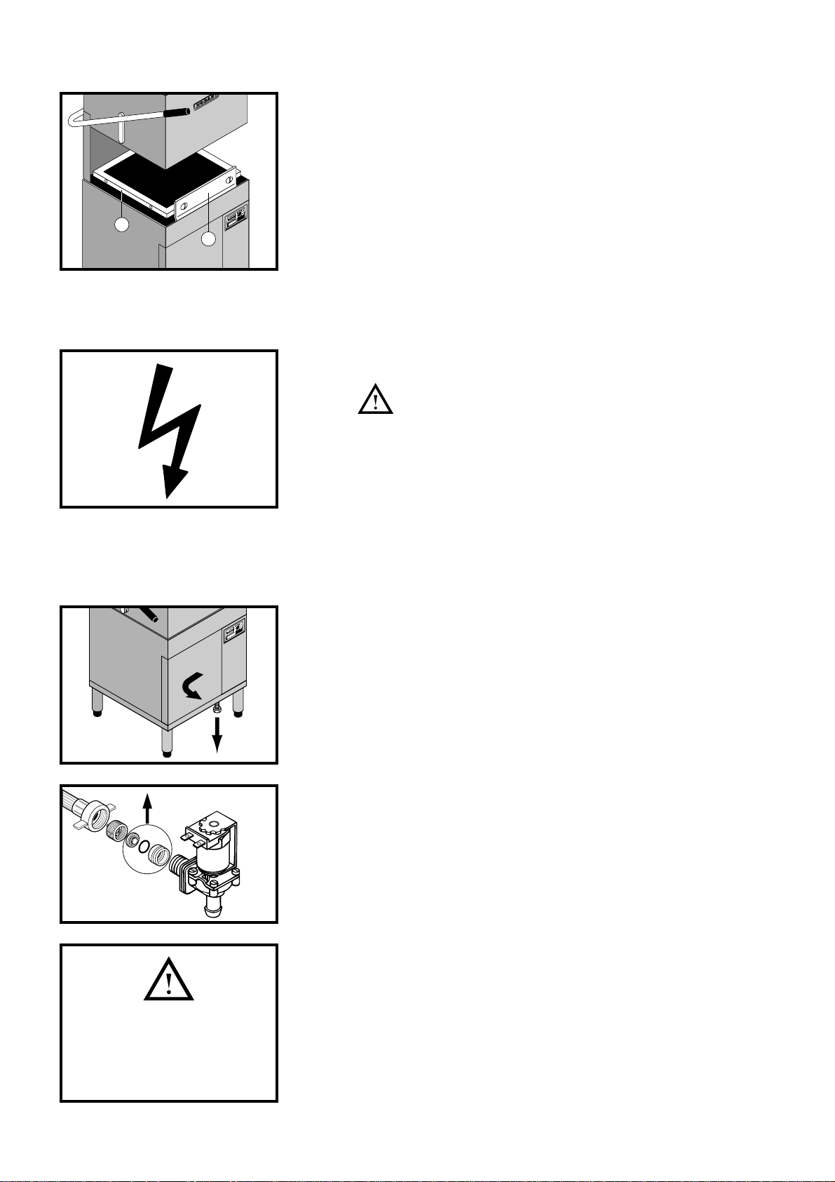
1.2 Converting to corner version
– Open the hood, unscrew guide rail A and fix it to position B.
– To set the tables see installation plan.
2 Connections
2.1 Electrical connection
must be carried out by an authorized technician
according to the local and national codes.
– Set main circuit breaker.
– Check machine specifications to make sure they correspond to
those of the site supply and to wiring diagram.
– Check site fuse rating.
According to EN 60 335 the appliance must be connected to a
equipotential conductor. The connecting screw is located beside
the cable inlet.
2
1
S
HX-30/40
All machines must be operated
with water of drinking quality.
For water with an extremely high
mineral content, water treatment
is recommended.
2.2 Water connection (HX-30/40)
– If possible to soft and warm water (4° Clark, max. 60°C).
– Line flow pressure 0.6 – 6 bar.
If line flow pressure is less than 0.7 bar:
(must be carried out by an authorized technician)
– Switch Off machine.
– Remove front panel.
– Unscrew panel with electrical parts.
– Disconnect the water supply hose from water inlet valve.
– T ake a way the sie ve (S) and remov e the diaphragm (see drawing).
– Replace the sieve and reconnect supply hose.
– If line flow pressure is above 6 bar pro vide pressure reducer .
– Connect flexible supply hose with union nut 3/4" to site connection.
– Fit shut-off valve.
Water connection (HX-30/40 S)
For U.K. see following page.
– If possible to warm water (max. 60°C).
– Machine is provided for flow pressure 1.4 – 6 bar as standard.
– If flow pressure is below 1.4 bar, please contact the HOBART
service.
– If flow pressure exceeds 6 bar, pressure reducer is required.
– Connect flexible supply hose with union nut 3/4" to site connection.
– Fit shut-off valve.
4
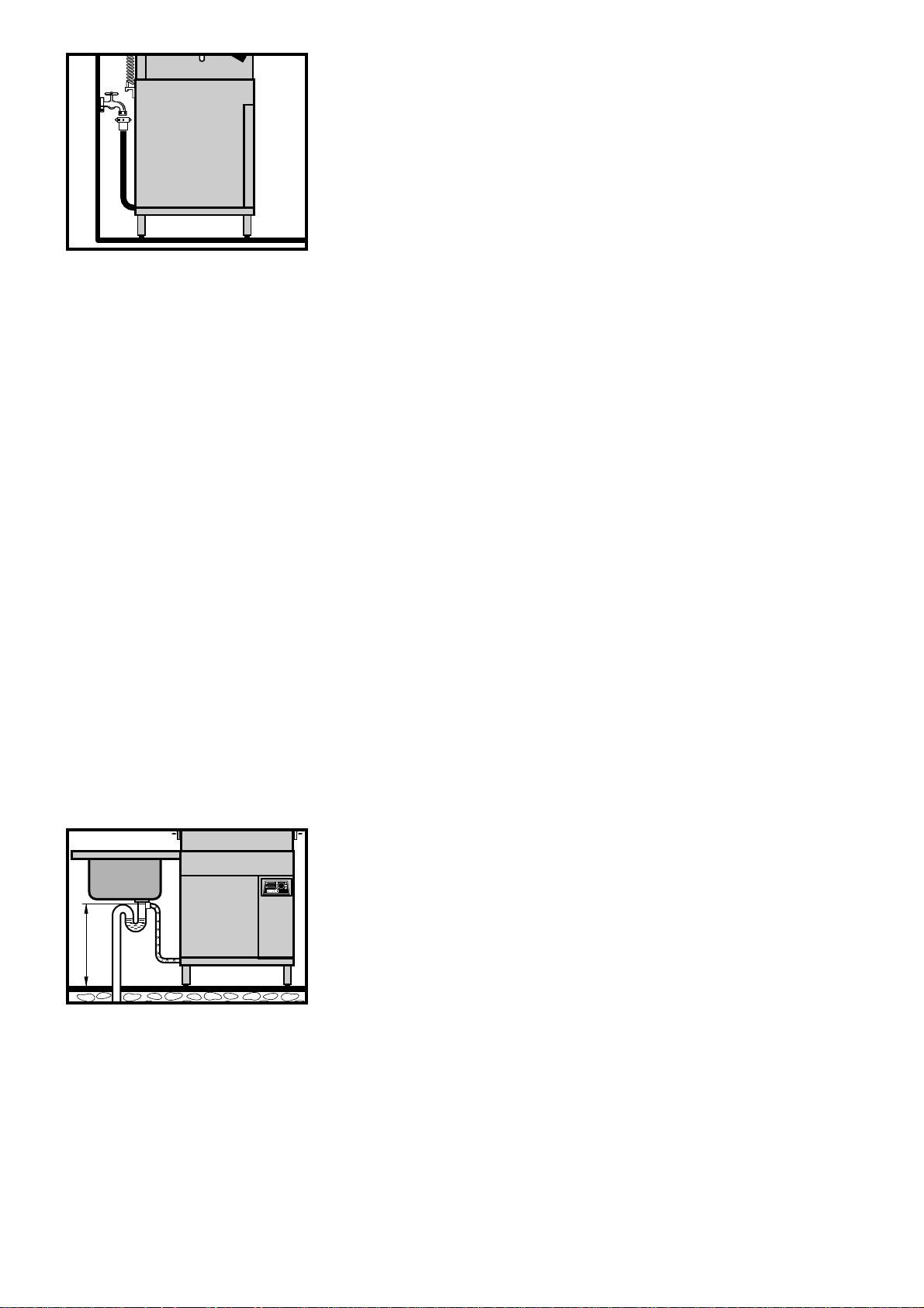
Water connection (HX-30/40 S) only for U.K.
All United Kingdom installations must be supplied from
storage not mains.
Direct connections to the mains supply contravenes Water
Authority Regulations.
– Connect if possible to warm water.
The supply water temperature should not exceed 60°C into the
machine.
For temperatures in excess of 60°C, a thermostatic mixing valve
should be fitted at installation. This valve is available from
HOBART Service Centres.
– Fit shut-off valve.
LOW PRESSURE SITUATIONS
Below 0.4 bar (6 psi) flow pressure there are two solutions.
a) Provide a suitable water storage tank at a height which will
create a pressure in excess of 0.4 bar or,
b) fit a water pump to increase the pressure.
A suitable pump can be supplied by HOBART at extra cost.
max. 1 m
MEDIUM PRESSURE SITUATIONS
0.4 – 0.7 bar (6-10 psi) flow pressure.
– Most installations will fall into this category and the machine will
arrive fitted with a solenoid valve designed for this pressure
range.
HIGH PRESSURE SITUATIONS
Above 0.7 bar flow pressure.
a) Fit a water storage tank at a suitable height.
b) Fit a pressure reducing valve during installation.
2.3 Drain Connection
– Connect to trapped drain line.
– Connection between machine and site drain may not exceed
max. height of drain pump lift of 1 m.
– Do not kink drain hose.
5
 Loading...