


N
S
T
R
U
C
T
I
O
N
S
I
HP15E SERIES
ELECTRIC PRESSURE FRYERS
MODELS
HP15ES ML-126820
HVH23 ML-126819 (Optional Hood)
701 S. RIDGE AVENUE
TROY, OHIO 45374-0001
937-332-3000
– 1 –
www.hobartcorp.com
FORM 34521, Rev. A (October 2001)

TABLE OF CONTENTS
GENERAL. . . . . . . . . . . . . . . . . . . . . . . . . . . . . . . . . . . . . . . . . . . . . . . . . . . . . . . . . . . . . . . . . . . . . . . 3
INSTALLATION . . . . . . . . . . . . . . . . . . . . . . . . . . . . . . . . . . . . . . . . . . . . . . . . . . . . . . . . . . . . . . . . . . 3
Unpacking . . . . . . . . . . . . . . . . . . . . . . . . . . . . . . . . . . . . . . . . . . . . . . . . . . . . . . . . . . . . . . . . . 3
Location . . . . . . . . . . . . . . . . . . . . . . . . . . . . . . . . . . . . . . . . . . . . . . . . . . . . . . . . . . . . . . . . . . 4
Installation Codes and Standards . . . . . . . . . . . . . . . . . . . . . . . . . . . . . . . . . . . . . . . . . . . . . . 5
Assembly . . . . . . . . . . . . . . . . . . . . . . . . . . . . . . . . . . . . . . . . . . . . . . . . . . . . . . . . . . . . . . . . . 5
Leveling . . . . . . . . . . . . . . . . . . . . . . . . . . . . . . . . . . . . . . . . . . . . . . . . . . . . . . . . . . . . . . . . . . 7
Electrical Connections . . . . . . . . . . . . . . . . . . . . . . . . . . . . . . . . . . . . . . . . . . . . . . . . . . . . . . . 7
Optional Ventless Exhaust Hood. . . . . . . . . . . . . . . . . . . . . . . . . . . . . . . . . . . . . . . . . . . . . . . 8
Before First Use . . . . . . . . . . . . . . . . . . . . . . . . . . . . . . . . . . . . . . . . . . . . . . . . . . . . . . . . . . . 12
System Test . . . . . . . . . . . . . . . . . . . . . . . . . . . . . . . . . . . . . . . . . . . . . . . . . . . . . . . . . . . . . . 13
OPERATION . . . . . . . . . . . . . . . . . . . . . . . . . . . . . . . . . . . . . . . . . . . . . . . . . . . . . . . . . . . . . . . . . . . 14
Controls . . . . . . . . . . . . . . . . . . . . . . . . . . . . . . . . . . . . . . . . . . . . . . . . . . . . . . . . . . . . . . . . . 14
Reprogramming Set Temperature and/or Time . . . . . . . . . . . . . . . . . . . . . . . . . . . . . . . . . . 15
Filling the Kettle with Liquid Shortening . . . . . . . . . . . . . . . . . . . . . . . . . . . . . . . . . . . . . . . . 16
Using the Pressure Fryer . . . . . . . . . . . . . . . . . . . . . . . . . . . . . . . . . . . . . . . . . . . . . . . . . . . . 16
Power Failure . . . . . . . . . . . . . . . . . . . . . . . . . . . . . . . . . . . . . . . . . . . . . . . . . . . . . . . . . . . . . 18
Food Preparation . . . . . . . . . . . . . . . . . . . . . . . . . . . . . . . . . . . . . . . . . . . . . . . . . . . . . . . . . . 18
Cooking Guidelines . . . . . . . . . . . . . . . . . . . . . . . . . . . . . . . . . . . . . . . . . . . . . . . . . . . . . . . . 19
High-Limit . . . . . . . . . . . . . . . . . . . . . . . . . . . . . . . . . . . . . . . . . . . . . . . . . . . . . . . . . . . . . . . . 19
Pop-Off Valve . . . . . . . . . . . . . . . . . . . . . . . . . . . . . . . . . . . . . . . . . . . . . . . . . . . . . . . . . . . . . 20
Draining and Filtering Oil . . . . . . . . . . . . . . . . . . . . . . . . . . . . . . . . . . . . . . . . . . . . . . . . . . . . 20
Cleaning . . . . . . . . . . . . . . . . . . . . . . . . . . . . . . . . . . . . . . . . . . . . . . . . . . . . . . . . . . . . . . . . . 21
MAINTENANCE . . . . . . . . . . . . . . . . . . . . . . . . . . . . . . . . . . . . . . . . . . . . . . . . . . . . . . . . . . . . . . . . . 26
O-Ring Seal Replacements . . . . . . . . . . . . . . . . . . . . . . . . . . . . . . . . . . . . . . . . . . . . . . . . . . 26
Service and Parts Information . . . . . . . . . . . . . . . . . . . . . . . . . . . . . . . . . . . . . . . . . . . . . . . . 26
TROUBLESHOOTING GUIDE . . . . . . . . . . . . . . . . . . . . . . . . . . . . . . . . . . . . . . . . . . . . . . . . . . . . . 27
© HOBART CORPORATION, 2001
– 2 –

INSTALLATION, OPERATION, AND CARE OF
HP15E SERIES ELECTRIC PRESSURE FRYERS
PLEASE KEEP THIS MANUAL FOR FUTURE USE
GENERAL
The HP15E Series electric pressure fryers produce uniform, high quality product and operate at a low
temperature (325°F/163°C) and pressure (13 psig). Fast, pressure frying increases production,
improves energy efficiency, preserves food flavor, and reduces shrinkage. Up to 15 pounds of product
can be cooked in each batch.
The optional hood (Model HVH23) includes a nonvented exhaust fan with a three-stage air filtration
system. Models with the hood also include an ANSUL
Model HMF50 is a portable 115-volt filter, available from Hobart, which may be used to filter the cooking
oil. Use of the HMF50 is covered in a separate manual shipped with the filter.
Standard equipment includes:
Drain pipe extension
1
1
/4" diameter exhaust pipe (for models without the hood)
1
/4" pipe plug (for models with the hood)
1
Stainless steel vat
Open-end wrench (used for teardown during cleaning)
Flexible cleaning rod
Four casters
Extra O-Ring seals for the lid, the kettle pressure regulator assembly, and the cleaning port plug screw
are also included.
Models are designed for a 208- or 240-volt, 1- or 3-phase electrical supply. Standard wiring is 208-volt,
3-phase. Single-phase models are rated at 75 amps; 3-phase models are rated at 35 amps.
®
Fire Suppression System.
INSTALLATION
Before installing, verify that the electrical service agrees with the specifications on the rating plate
located on the right side panel as you face the pressure fryer. If the supply and equipment requirements
do not agree, do not proceed with the installation. Contact Hobart Corporation immediately.
UNPACKING
This pressure fryer was inspected before leaving the factory. The transportation company assumes full
responsibility for safe delivery upon acceptance of the shipment. Immediately after unpacking, check
for possible shipping damage. If the pressure fryer is found to be damaged, save the packaging material
and contact the carrier within 15 days of delivery.
– 3 –
Carefully unpack the pressure fryer and place in a work-accessible area as near to its final installed
position as possible.
Do not use the door to lift or move the pressure fryer.
Check off the accessories packed with the pressure fryer and the optional ventless exhaust hood (if so
equipped).
Pressure Fryer Optional Hood
Frying basket and handle
Instruction manual and parts list
Hood and fire suppression system
ANSULEX® Fire Suppressant, 1.5 gal. (5.7 L)
Four legs, pressure fryer cabinet Rear (outer) exhaust manifold
Four swivel casters (two locking, two standard) Front (inner) exhaust manifold
Drain pipe extension Drip cup, inner manifold
Solenoid wrench and flexible cleaning rod Two manifold gaskets
Two replacement diaphragm gaskets Spacer bar, drilled
Wooden doughnut stick (for clearing kettle drain) Grease filter
Crumb catcher Air filter
Warranty registration (inside manual) Charcoal filter
Tube of RTV108 adhesive sealant
Pipe plug for condensation tank
Mounting Hardware:
Four 1/4-20 x 1" hex head screws
Four 1/4-20 wing nuts
LOCATION
The installation location must allow adequate clearances for servicing and proper operation. Required
minimum clearance from side and back is 1" (2.5 cm)
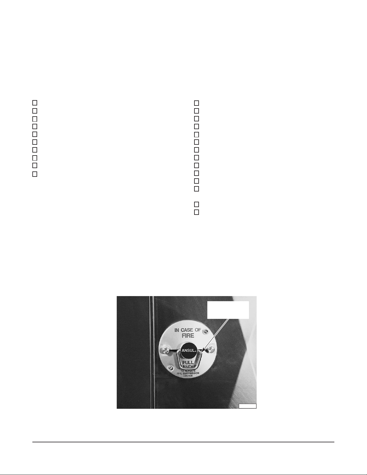
. If your pressure fryer is equipped with the optional
hood, a minimum clearance of 30" (76 cm) is required on the left side of the exhaust hood to permit
operation of the manual actuator of the fire suppression system (Fig. 1).
Fig.1
– 4 –
MANUAL PULL FOR
FIRE SUPPRESION
SYSTEM
PL-41452-1

INSTALLATION CODES AND STANDARDS
The pressure fryer and ventless exhaust hood (if so equipped) must be installed in accordance with:
In the United States of America:
1. State and local codes.
2. National Electrical Code, ANSI/NFPA-70 (latest edition). Copies may be obtained from The
National Fire Protection Association, Batterymarch Park, Quincy, MA 01169.
3. NFPA Standard #96,
Vapor Removal from Cooking Equipment,
available from The National Fire
Protection Association, Batterymarch Park, Quincy, MA 01169. (The optional ventless exhaust
hood and the fire suppression system, if so equipped, already meet NFPA Standard #96 without
requiring a separate exhaust hood.)
In Canada:
1. Local codes.
2. Canadian Electrical Code, CSA C22.1 (latest edition). Copies may be obtained from The
Canadian Standard Association, 178 Rexdale Blvd., Etobicoke, Ontario, Canada M9W 1R3.
ASSEMBLY
Casters (Fig. 2)
Place the pressure fryer on its side, being careful to avoid scratching the surface. Use only the casters
supplied with the pressure fryer. Thread the four casters to the flanges on the bottom corners of the
pressure fryer. Use the open-ended wrench supplied to tighten (apply wrench at the flat surfaces on
leg extensions). The two locking casters mount at the front; the nonlocking casters mount at the rear.
Fig. 2
– 5 –
TIGHTEN AT FLATS
PL-51559
Exhaust Pipe (Models Without the Ventless Exhaust Hood)
Thread the 1
1
/4" diameter exhaust pipe (supplied) to the top of the exhaust tank at the rear of the fryer
(Fig. 3). This pipe should be at least 60" (1.5 m) in length. Use teflon tape or equivalent to seal.
EXHAUST PIPE
SUPPLIED BY INSTALLER
1 1/4" PIPE
THREAD
CONDENSATION
TANK
AC CONDUIT
AC INSPECTION BOX
Fig. 3
DRAIN VALVE,
CONDENSATION
TANK
EXHAUST PIPE
PL-53522
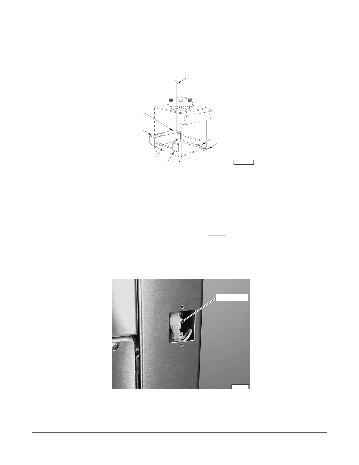
Jumper Plug (Models Without the Ventless Exhaust Hood)
A single-wire jumper plug, with male pins in positions 1 and 2, MUST be plugged into the floating five-pin
hood receptacle located behind the cover plate at the rear of the pressure fryer (Fig. 4). This receptacle,
with five female pins, would otherwise mate to the five-pin hood plug. The fryer
will not operate
without
either the hood plug or the jumper plug in place.
JUMPER PLUG
PL-41453-1
Fig. 4
– 6 –
LEVELING
Casters for this pressure fryer are of the nonadjustable type. Therefore, the floor must be level. If floor
surface is not level, the pressure fryer will experience cooking problems.
ELECTRICAL CONNECTIONS
WARNING: ELECTRICAL AND GROUNDING CONNECTIONS MUST COMPLY WITH THE
APPLICABLE PORTIONS OF THE NATIONAL ELECTRICAL CODE AND/OR OTHER LOCAL
ELECTRICAL CODES.
WARNING: DISCONNECT ELECTRICAL POWER SUPPLY AND PLACE A TAG AT THE DISCONNECT
SWITCH TO INDICATE YOU ARE WORKING ON THE CIRCUIT.
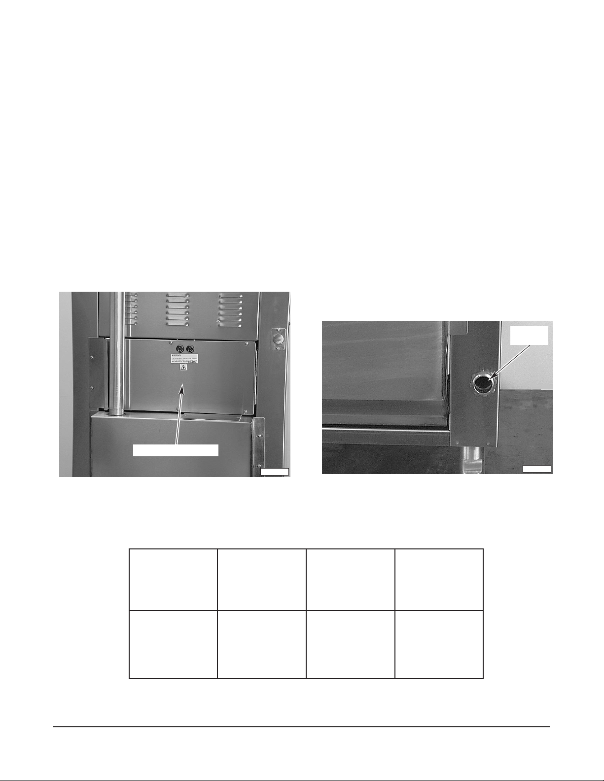
The wiring compartment is located behind the panel (Fig. 5) at the rear of the pressure fryer. Open the
wiring compartment cover and make electrical connections per the wiring diagram located on the inside
of the compartment door. Feed cord through the conduit hole (Fig. 6), exiting at the rear of the fryer.
CORD
CONDUIT
WIRING COMPARTMENT
PL-41454-1
Fig. 5 Fig. 6
ELECTRICAL DATA
STLOVZTREHESAHP
022-802/021
042/021
802
042
* Three-wire system requires three copper wires insulated to 90°C.
** Maximum Circuit Breaker Size/Minimum Circuit Amperage compiled in accordance with the National Electrical Code, latest edition.
06
06
06
06
1
1
3
3
57
57
53
53
**EZISTIUCRIC
)spmA(
PL-41455-1
– 7 –
OPTIONAL VENTLESS EXHAUST HOOD
The ventless exhaust hood is a self-contained air filtration system and includes a fire suppression
system manufactured by ANSUL
®
Fire Protection, 1 Stanton Street, Marinette, Wisconsin 54143. It
enables operation of the pressure fryer in a location without an externally-exhausted ventilation hood
and wall-mounted fire suppression system. The three-stage filtration system removes oil particles,
®
steam and condensation, and cooking odors from the exhaust air. The ANSUL
Fire Suppression
System actuates automatically if the temperature below the hood exceeds 165°F (74°C), or it can be
manually triggered by the operator. In either case, fryer operation will be disabled. A damper at the
blower outlet will close automatically to restrict air flow to the fire.
The ANSUL® Fire Suppression System must be charged and certified by an authorized ANSUL® dealer.
®
Hobart Corporation is not permitted to service the fire suppression system; only an ANSUL
®
properly maintain the fire suppression system. The ANSUL
representative must also adjust the nozzle
dealer may
of the system at the time of charging.
The ANSUL
A separate instruction manual is provided that details the ANSUL
®
system must be fully charged and operational for your appliance to be operational.
®
Fire Suppression System.
Safety interlocks disable operation of the fryer if (a) the fire suppression system is not charged and
cocked; (b) one or more filters are missing or incorrectly installed; or (c) the exhaust blowers are not
operating. Indicator lights aid troubleshooting by pinpointing open interlock switches.
Installation
The ventless exhaust hood is shipped separately from the pressure fryer. Assembly of the ventless
exhaust hood to the pressure fryer will require a minimum of two people. It is recommended that you
install and connect the hood assembly prior to powering the fryer.
To prepare the pressure fryer:
1. Make sure the front casters on the pressure fryer are locked before installing the hood.
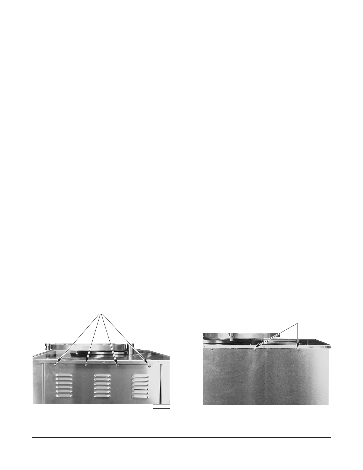
2. Remove and retain the four 10-32 pan head screws from the upper rear of the cabinet below the
countertop lip of the pressure fryer (Fig. 7).
REMOVE 2 SCREWS FROM
REMOVE 4 SCREWS
RIGHT REAR SIDE PANEL
AND 2 SCREWS FROM
LEFT REAR SIDE PANEL
PL-41456-1
Fig. 7 Fig. 8
– 8 –
PL-41457-1
3. Remove and retain two 10-32 pan head screws from the left side panel on the upper rear of the
cabinet and two from the upper rear right side of the cabinet (Fig. 8).
4. Remove the hood from the skid.
• Remove four screws at the rear of the hood.
• Remove two screws from the right side and two screws from the left side of the hood.
5. With two people, lift the hood from the skid and place it on top of the pressure fryer.
6. While one person holds the hood in place, line up the holes of the pressure fryer with the holes
in the hood. Start the four side screws (supplied) first.
7. Slide the drilled spacer bar under the rear overhanging lip of the hood and secure, using the four
rear screws.
8.
Caulk the joints between the hood and the pressure fryer countertop on the inside surface (Fig. 9).
Use silicone rubber adhesive sealant (General Electric RTV108, or equivalent). Observe
manufacturer's instructions for correct application. Allow the sealant to cure thoroughly before
using the pressure fryer.
9. Remove and discard the cover plate from the top of the condensation tank (Fig. 10) at the rear
of the pressure fryer. Retain the screws and leave the gasket in place.
APPLY ADHESIVE SEALANT RTV108
Fig. 9 Fig. 10
PL-41458-1
REMOVE COVER PLATE
PL-41459-1
– 9 –

10. Mount the base of the outer exhaust manifold to the top of the condensation tank (Fig. 11) and
PL-41461-1
DRIP CUP
INNER EXHAUST MANIFOLD
10. Mount the base of the outer exhaust manifold to the top of the condensation tank (Fig. 11) and
secure with the two flat head
secure with the two flat head
1
1
/4-20 screws.
/4-20 screws.
11. Install the inner exhaust manifold (Fig. 12) to the inside of the hood using the four
1
/4-20 hex head
screws and four wing nuts provided. Insert a gasket between each manifold and its mating
surface of the hood.
12. Slide the drip cup (Fig. 12) into the slots below the trough.
OUTER
EXHAUST
MANIFOLD
CONDENSATION
TANK
PL-41460-1
Fig. 11 Fig. 12
Fig. 11 Fig. 12
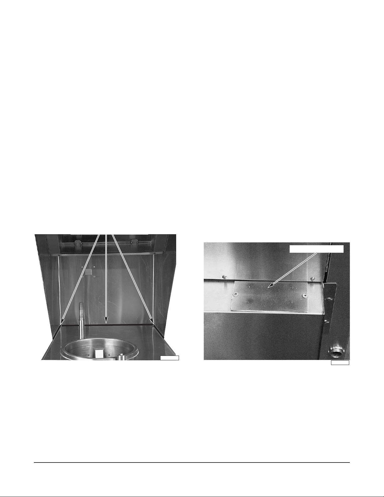
13. Remove the cover plate (Fig. 13) at the right rear of the fryer.
13. Remove the cover plate (Fig. 13) at the right rear of the fryer.
14. Locate the five-pin female receptacle at the right of the solenoid box (Fig. 14). Remove and
14. Locate the five-pin female receptacle at the right of the solenoid box (Fig. 14). Remove and
discard the jumper plug (if present).
discard the jumper plug (if present).
15. Connect the five-pin male hood plug to the five-pin female receptacle.
15. Connect the five-pin male hood plug to the five-pin female receptacle.
16. Install the 1
1
/4" pipe plug (supplied) into the opening on the left side of the condensation tank.
COVER PLATE
PL-41462-1
JUMPER PLUG
PL-41463-1
17. Apply power to the fryer.
Fig. 13
Fig. 14
– 10 –

Positioning Hood Filters
The three hood filters must be in their proper positions or your appliance will not function. Figure 15
shows the long, welded pins (three on the right and three on the left) against which the filters rest.
Directly behind the pins on the left side are three shorter filter actuator switch pins that push in and out.
Place each filter so that it pushes its filter actuator switch pin in, or your appliance will not operate.
WELDED PINS
GREASE FILTER
ACTUATOR PIN
AIR FILTER
ACTUATOR PIN
CHARCOAL FILTER
ACTUATOR PIN
PL-40086-1
Fig. 15
Remove the plastic cover from the charcoal filter. The charcoal filter goes to the rear of the hood. Make
certain it is pulled downward to engage the actuator of the interlock switch. Notice (Fig. 16) that the
actuator pin is pushed in and the filter is resting against the last set of welded pins.
CHARCOAL FILTER ACTUATOR PIN
CHARCOAL
FILTER
Fig. 16
– 11 –
PL-40087-1

Install the air filter onto the center set of pegs (Fig. 17), again making certain that the switch actuator
is engaged. The grease filter is installed last at the front of the hood (Fig. 18). It rests into front and
rear support channels. Pull the handles down to ensure a close fit and to engage the interlock switch
actuator.
AIR FILTER
PL-40088-1
Fig. 17 Fig. 18
GREASE FILTER
Insertion and removal of the filters is described in the CLEANING section of this manual.
Indicator Lights
PL-40089-1
Interlock Light — When lit, indicates all hood interlock switches are closed.
ANSUL
®
Light — When lit, indicates the fire suppression system is cocked and charged.
FIP (Filter-In-Place) Light — When lit, indicates all filters are properly installed.
Sail Light — When lit, indicates the exhaust blower is operating and moving an
adequate volume of air.
Reset Pushbutton Switch — Momentarily overrides sail switch to allow the exhaust blower to start.
BEFORE FIRST USE
WARNING: DISCONNECT ELECTRIC POWER SUPPLY AND PLACE A TAG AT THE DISCONNECT
SWITCH TO INDICATE YOU ARE WORKING ON THE CIRCUIT BEFORE CLEANING.
Clean the pressure fryer and hood (if so equipped) with warm soapy water. Rinse thoroughly and drain
in a drainage receptacle. Wipe completely dry with a soft, clean cloth. Clean all fryer and hood (if so
equipped) accessories. Rinse thoroughly after cleaning and wipe dry.
– 12 –

SYSTEM TEST
1. Make certain the drain valve below the bottom of the kettle is in the CLOSED position. Pour liquid
shortening into the kettle to the MINIMUM line (Fig. 19). Heat will cause the oil to expand and
reach the MAXIMUM line when hot. Use ONLY liquid, all-vegetable, hydrogenated shortening in
the pressure fryer. Never use drippings, lard, suet, or olive oil.
MINIMUM MAXIMUM
Fig. 19
CRUMB CATCHER
PL-41595-1
2. Turn the power switch to the ON position. If the fryer is equipped with the optional ventless
exhaust hood, all three hood filters must be in place.
3. After the fryer is turned on, the L.E.D. screen will display PrE-HEAt, alternating with the rising oil
temperature in degrees Fahrenheit. When the oil temperature reaches 325°F (163°C) or the
programmed temperature, the screen will display rEAdy, and an audible tone will sound for
seconds. The screen will then display idLE until a program (frying cycle) is initiated.
2
4. Turn the power switch to the OFF position.
– 13 –

OPERATION
WARNING: HOT OIL AND PARTS CAN CAUSE BURNS. USE CARE WHEN OPERATING, CLEANING
AND SERVICING THE FRYER.
WARNING: SPILLING HOT OIL CAN CAUSE SEVERE BURNS. DO NOT MOVE THE PRESSURE
FRYER WITHOUT DRAINING ALL OIL FROM THE TANK.
CONTROLS (Fig. 20)
Display Screen — Shows temperature, times and current mode of operation.
Power Switch — Press ON to turn the fryer on; press OFF to turn the fryer off. The digital
controller maintains a cooking temperature of 325°F (163°C), or preset
programmed temperature.
Keypad —
(Program keys 1 thru 6.) After allowing the fryer to complete its heating period,
press a numbered program key to start a preprogrammed cooking cycle.
Key Preprogrammed Time
1 12 minutes (fresh chicken)
2 19 minutes (frozen chicken)
3 4 minutes (chicken strips)
4 7 minutes (potatoes)
5 5 minutes (fish)
6 1 minute (fresh vegetables)
Red Heat Light — When lit, indicates the heating elements are providing heat to the pressure
fryer.
Red High-Limit Light — When lit, indicates oil temperature is higher than normal. The pressure fryer
will shut off and the pressure will be exhausted. The high limit thermostat will
reset automatically once the oil temperature cools to below the high-limit
temperature.
Pressure Gauge — (Not shown. Located on top of kettle lid.) Indicates internal kettle pressure
in pounds per square inch, gauge (psig).
DISPLAY
SCREEN
POWER
SWITCH
RED HEAT
LIGHT
00:00.00
1
2
EDIT
EXIT
ENTER
4
BACK-UP
3
5
6
RED HIGH
LIMIT LIGHT
KEYPAD
Fig. 20
– 14 –
ON
OFF
PL-55682

REPROGRAMMING SET TEMPERATURE AND/OR TIME
Any of the program keys may be reprogrammed if a different time or temperature is desired.
ACTION
1. Enter Program Mode
•
Press both Keys 3 (Up) and 6 (Down), and hold for 2 seconds.
• Key 1 is already programmed for fresh chicken, so press
Key 3 (Up) to change display.
2. Change Temperature
• Press Key 1 tells controller you are changing temp.
• Press Key 1 (Edit) a second time.
• Hold Key 3 (Up) or Key 6 (Down) to set temperature.
• Press Key 2 (Enter) to save the setting.
3. Change Time
• Press Key 3 (Up) tells controller you are changing time.
• Press Key 1 (Edit) and set the desired cooking time for
Menu Item 2; for example, 19 minutes for frozen chicken.
DISPLAY SHOWS
M 1 (Menu Number 1)
M 2 (Menu Number 2)
StPt 1 (Setpoint 1),
alternating with 32°F
Temperature selection
Temperature selection
tinE 1 (Time 1),
alternating with :00
Time selection
• Hold Key 3 (Up) or Key 6 (Down) until the display reads
19:00.
• Press Key 2 (Enter) to save the setting.
4. Exit Programming Mode
• Press and hold Key 4 (Exit) until the display screen blanks.
This exits the programming mode and returns the controller
to normal operating mode.
The controller memory will remember only the last figures programmed under any key. Turning the
fryer off, or any other power interruptions, will not affect the controller settings last saved into memory.
If a program key with no preprogrammed cooking time is pressed, the controller will not respond. The
display will continue to show idLE until a programmed key is selected.
Any program, once initiated, can be cancelled by pressing and holding the lighted program key until
the light on the key extinguishes.
In the event of a program malfunction or error message, turn the power switch OFF, pause for
seconds, then turn power switch ON. The display should read prE-HEAt, and the red heat light will
10
glow if the oil has cooled. If the error message reappears, contact your local Hobart service office.
19:00
19:00
Blank
idLE (Idle)
– 15 –

FILLING THE KETTLE WITH LIQUID SHORTENING
Oil Capacity: 26 pounds (12 kg).
Use only a pure, vegetable, hydrogenated oil prescribed for use in pressure fryers, such as Mel Fry,
Crystal, FryMax, or Gold Label. Never add suet.
Close drain valve (Fig. 21). Fill kettle with liquid shortening; solid shortening is not recommended.
• If shortening is hot, fill kettle to the MAXIMUM line on the crumb catcher probe cover (Fig. 22).
• If shortening is room temperature, fill kettle to the MINIMUM line. This level allows for oil
expansion when heated. Do not overfill.
Regularly add enough oil to keep the oil level in the kettle to the MAXIMUM line.
When changing to new oil, keep the level at the MINIMUM line.
DO NOT operate the fryer with no oil in the kettle.
DRAIN VALVE HANDLE
Fig. 21
MINIMUM MAXIMUM
PL-41465-1
Fig. 22
CRUMB CATCHER
PL-41595-1
USING THE PRESSURE FRYER
CAUTION: Before turning the fryer on, the kettle must be filled to the correct level with liquid
shortening. If this is not done, the kettle walls can be damaged. Warpage can cause leaks.
Pressure is created by the containment of moisture escaping from the product being fried. Dry products
that produce little or no moisture will not create sufficient pressure to pressure-fry that product.
Pressure will not build without product in the kettle.
1. Place the power switch in the ON position. If the fryer is equipped with the optional ventless
exhaust hood, all three hood filters must be in place.
2. After the fryer is turned on, the display will show prE-HEAt, alternating with the rising oil
temperature in degrees Fahrenheit.
– 16 –

3. When the oil temperature reaches 325°F (163°C) or the programmed temperature, the screen will
display rEAdy and an audible tone will sound for 2 seconds. The screen will then display idLE
until a program (frying cycle) is initiated. After the screen reads idLE, place the frying basket into
the oil and proceed with cooking.
4. Using tongs or other long-handled utensil, place prepared foods evenly around the basket, one
piece at a time. Load food in a circular motion so the basket is loaded uniformly and evenly.
5. After loading ten to twelve pieces of food, use insulated mitts and lift the basket high enough to
clear the bottom of the kettle. Swirl the basket a couple of times in the oil to keep pieces from
sticking together.
6. Lift the basket out of the oil and hang the basket on the lip of the kettle. Continue loading the food
(maximum capacity is 15 pounds (7 kg) of food). When the desired amount of food is placed in
the basket, give the basket one more swirl in the oil. Close the lid. Make sure the lock post is
fastened in the overarm post catch (Fig. 23). Hold the front post in place while tightening the
handle.
WARNING: IF THE LID WILL NOT LOCK, DO NOT OPERATE THE FRYER.
OVERARM
POST CATCH
PL-41596-1
Fig. 23
7. After tightening the lid, press the desired program key (1 to 6). The light above the selected
program key will light. The display screen will show the preprogrammed cooking time, then count
down to 00:00, and cooking will begin. Once a program is started, there is a 5-second delay
before there is any response to further program key presses.
8. If you wish to cancel the cooking cycle before the end of the preset time, press the selected
program key again and hold for 2 seconds. Cooking will stop and the display will show rEAdy.
9. If you press the wrong program key, you can change it, but you must do it within 30 seconds. To
change your selection, press the
wrong program key again and hold it in until the indicator light
on the key extinguishes. The fryer will stop cooking. Then press the correct program key.
– 17 –

10. The heat light and the heating elements will continue to cycle on and off and product will continue
to cook until the audible tone sounds at the end of the cooking cycle. Pressure will automatically
begin to release 45 to 60 seconds prior to the audible tone sounding. The selected program key
will flash.
11. At the end of the frying cycle, the audible tone will sound and continue sounding until turned off
manually. Press the flashing program key to silence the audible tone.
12. When the pressure gauge reads 0 and the lid lock releases, turn the handle counterclockwise
until it stops before opening the lid. CAUTION: Seal damage can occur if the handle is not
completely unscrewed. Do not force the lid to open.
When loading and unloading product, always swing the lid to the side. Do not raise the lid.
13. Using insulated mitts, grasp the basket handle and raise the frying basket out of the oil. Hang the
basket on the lip of the kettle. Allow food to drain approximately 20 to 25 seconds. Remove the
food and return the basket to the oil. It is not necessary to turn the fryer off for unloading. Allow
the kettle to recover and maintain the oil temperature, and mimimize the time between loads.
14. It is advisable to inspect the first load. If preparing unusually large pieces, or if product is only
partially thawed, it may be necessary to increase cooking time (not temperature) to compensate.
Turning the Fryer Off
When the display shows idLE, turn the power switch to OFF.
Extended Shutdown
1. When the display shows idLE, turn the power switch to OFF.
2. Clean the fryer following the instructions in the CLEANING section of this manual. The solenoid
assembly must be cleaned thoroughly and routinely.
POWER FAILURE
In the event of a power failure, turn the power switch to OFF. After the pressure gauge indicates 0, open
the kettle lid and remove the basket. If interrupted, the program will automatically cancel after 60
seconds of power loss.
Repeat all startup procedures upon resumption of electrical service. The controller resets to its wakeup mode, and can be restarted by turning the power switch to ON and allowing the fryer to cycle through
its automatic preheat stage.
FOOD PREPARATION
Pressure frying seals in the natural moisture of food products and uses 30% less frying oil. It should
be remembered, however, that no food prepared in the Hobart pressure fryer will be any better than the
quality of the product purchased.
Trim excess skin and fat from product. Coat with your preferred breading. Allow the breading to set
up (become sticky) before frying; this takes about 20 minutes. If breading is not allowed to set up, it
may wash off in the hot oil.
– 18 –

Fresh chicken is frequently stored and sold in a hard-refrigerated state. Allow such product to thaw
completely before preparing or frying. Comply with safe handling procedures regarding thawing. Hardrefrigerated chicken may be thawed overnight under refrigeration. Frozen chicken is defined as
product sold as prebreaded chicken parts frozen to 0°F (-18°C) or below, and is intended for immediate
frying without thawing or additional preparation. Use care when loading frozen chicken parts into the
kettle, as ice crystals on the product may cause the hot cooking oil to spatter.
COOKING GUIDELINES
The cooking guidelines in the chart below are suggested only. They are based on average-sized
portions. If unusually large pieces are not thoroughly cooked, increase cooking time, not temperature.
Frozen portions will require a longer cooking time. Maximum capacity is 15 pounds (6.8 kg), or
approximately 45 pieces of chicken. A typical load is considered to be 6 to 9 pounds (2.7 to 4 kg) of
raw, breaded chicken.
Time Temperature
Product (Minutes) (Degrees F) (Degrees C)
Fresh Chicken 12 325 163
Frozen Chicken 19 325 163
Chicken Strips 4 325 163
Fish Filets 5 325 163
Shrimp (Fresh) 4 325 163
Pork Chops 8 325 163
Veal Cutlets 7 325 163
Chicken Fried Steak 8 325 163
French Fries, Curly Fries (Frozen) 4 325 163
Onion Rings 1 325 163
Vegetables 1 325 163
HIGH-LIMIT
The pressure fryer is equipped with a high-temperature-limit switch that senses a higher than normal
temperature. If a higher than normal temperature is sensed by the high-temperature-limit switch, the
fryer will shut off and the pressure will be exhausted. Once the oil temperature cools to below the highlimit temperature, the high-limit thermostat will reset automatically. It is recommended that you turn the
power off and swing the kettle lid open to allow the oil to cool. After the kettle has cooled to normal
operating temperature, turn the power switch back on and resume the programmed cycle.
NOTE: The high-limit switch may activate during initial startup if the oil is hotter at the top of the kettle
than at the bottom. Normal operation will return after the oil temperature has stabilized. If the high-limit
switch activates anytime after initial startup, turn the pressure fryer off and call your local Hobart service
office.
– 19 –

POP-OFF VALVE
The pop-off valve is located on the fryer lid. This valve is nonadjustable and preset at the factory to
release the kettle pressure automatically if over 15 psig. The valve is also equipped with a ring (Fig. 24)
that should be lifted if kettle pressure exceeds 15 psig and the valve does not release the pressure
automatically. CAUTION: Do not allow kettle pressure to exceed 15 psig. Keep the exhaust port
of the pop-off valve clear of obstructions.
WARNING: STEAM RELEASED BY THE POP-OFF VALVE MAY CAUSE BURNS. USE CAUTION
WHEN OPENING THE VALVE.
Do not use the pop-off valve to manually relieve pressure as a regular practice. Allow pressure to
release automatically.
POP-OFF VALVE RING
PL-41467-1
Fig. 24
DRAINING AND FILTERING OIL
WARNING: HOT OIL AND PARTS CAN CAUSE BURNS. USE CARE WHEN OPERATING,
CLEANING, OR SERVICING THE FRYER.
WARNING: DO NOT DRAIN OR FILTER OIL WHILE KETTLE IS UNDER PRESSURE.
To prolong oil life, it is recommended that you filter the oil after 85 to 90 pounds (39 to 41 kg) of product
has been cooked. Filter the cooking oil using the Hobart HMF50 portable filter, or with a vacuum-style
or gravity-style filter by others. Draining through cheesecloth will not clean the oil sufficiently for
pressure frying.
Using the HMF50 Portable Filter: Follow the instructions shipped with the unit.
Filtering Oil and Cleaning Kettle at the End of the Production Day
This procedure must be performed daily while the kettle is still warm. Filtering time increases as the
oil cools.
1. Turn fryer power switch to OFF before draining or filling. Open the lid.
2. If you use filter powder (diatomaceous earth), follow the manufacturer's instructions and add filter
powder to the oil in the kettle. Stir with the wooden doughnut stick provided.
– 20 –

3. Position filtering system under the drain, open the drain valve, and drain oil until approximately
2" (5 cm) of oil remains in the kettle.
4. Using a long-handled brush, wash sides and bottom of kettle with the remaining warm oil, then
finish draining tank.
5. While oil is out of the kettle, remove any excess breading from the crumb catcher (see Fig. 22).
Use the wooden doughnut stick provided to dislodge any material that may have collected in the
kettle drain.
6. CAREFULLY pour 2 to 3 gallons (7.6 to 11.3 L) of COLD water into the kettle. Use a nylon pad
(nonabrasive, plastic web-type, nonrusting, nonshredding pad) to wash the kettle completely.
Drain the water into a drainage receptacle. Rinse the kettle well with clear water. Drain again.
Wipe the kettle dry with a soft, clean, lint-free cloth. Close the drain valve.
7. Return the oil to the kettle. Check the oil level.
8. If cooking is to resume following the filtering operation, turn the power switch to ON and allow the
fryer to heat. When the oil reaches cooking temperature (display shows idLE), place the frying
basket into the oil and begin cooking.
9. If cooking has concluded for the day, clean the fryer according to the CLEANING procedures
below.
CLEANING
WARNING: DISCONNECT ELECTRICAL POWER SUPPLY AND PLACE A TAG AT THE DISCONNECT
SWITCH TO INDICATE YOU ARE WORKING ON THE CIRCUIT BEFORE CLEANING.
Daily Cleaning
1. Before returning oil to the kettle following the final filtering operation of the day, close the drain
valve and pour 1 or 2 gallons (3.8 or 7.6 L) of cold water into the kettle. Use a web-type,
nonshredding, nylon scrubbing pad and thoroughly wash down the interior of the kettle. Drain the
wash water into a pail and discard. Towel dry the interior of the kettle.
2. Close the kettle drain valve and return the filtered oil to the kettle. Add fresh oil as required to
maintain the correct oil level.
3. Clean stainless steel regularly with a damp cloth and polish with a soft, dry cloth. If regular
cleaning is neglected, grease will be burned on and discolorations may form. These may be
removed by washing with any detergent or soap and water. Particularly stubborn discolorations
may be removed with a self-soaping scouring pad or a paste made of water and a mild scouring
powder applied with a plastic open pad or sponge. CAUTION: Always rub with the grain in a
horizontal direction.
4. It is important to keep the fryer exterior clean and free of accumulated grease. Wash all exterior
surfaces at least once daily. Use a cloth with warm water and a mild soap or detergent. Follow
with a clear rinse, then dry.
5. Wash the frying basket in hot, soapy water. Rinse thoroughly and dry.
– 21 –

6. Raise the lid by pulling the back knob (Fig. 25) out and lifting the lid up. Hold the back knob out
until you reach the desired height. Release the knob to hold the lid in that position. Wipe the under
part of the lid clean, including the diaphragm (Fig. 26).
BACK KNOB
PL-41596-2
Fig. 25
DIAPHRAGM
PL-41468-1
Fig. 26
7. Drain the condensation tank (Fig. 27). The condensation tank drain valve is located behind the
front access door at the lower right.
• Attach the drain pipe extension (supplied) to the condensation tank drain line (Fig. 27). Place
a pail below the extension and drain the condensation tank by turning the handle clockwise.
• After draining the condensation tank, turn the handle counterclockwise to close the drain valve,
then remove the drain pipe extension before closing the door.
When cleaning the area immediately surrounding the fryer (floor, walls), it may be necessary to move
the fryer from its installed position.
WARNING: SPILLING HOT OIL CAN CAUSE SEVERE BURNS. DO NOT MOVE THE PRESSURE
FRYER WITHOUT DRAINING ALL OIL FROM THE TANK.
Unplug the electrical cord.
EXHAUST PIPE
SUPPLIED BY INSTALLER
1 1/4" PIPE
THREAD
CONDENSATION
TANK
AC CONDUIT
AC INSPECTION BOX
DRAIN VALVE,
CONDENSATION
TANK
EXHAUST PIPE
PL-53522
Fig. 27
– 22 –

Weekly Cleaning
Solenoid Assembly (Fig. 28)
CAUTION: The kettle pressure-relief valve in the solenoid assembly must be cleaned at least
once a week during normal usage or the fryer may malfunction.
1. Open the kettle lid and remove the breather elbow (Fig. 29) from the inside wall of the kettle. Wash
the elbow in hot, soapy water, then rinse well and allow to air dry. Inspect the two O-Rings. If
cracked or worn, contact your local Hobart service office for replacement.
SOLENOID
CLEAN-OUT
PORT
HEX NUT
TEFLON GASKET
(INSIDE FITTING )
PRESSURE RELIEF VALVE
O-RING
PRESSURE REGULATOR
HOUSING
O-RING
THUMB
SCREW
PL-53523-E
Fig. 29Fig. 28
BREATHER ELBOW
PL-41469-1
2. Unplug the electrical cord attached to the upper portion of the solenoid assembly. To unplug, twist
the plug counterclockwise and pull out.
3. Remove thumb screw securing both the solenoid and pressure-relief valve. Separate the
solenoid and valve. The valve seats into the block with two O-Rings and some force may be
required.
.
4. Grasp the kettle pressure-relief valve with a towel and remove the valve from the solenoid. If the
1
hex nut on the base of the solenoid does not release easily, use the 1
/4" end wrench supplied.
Wash the valve in hot, soapy water. Rinse in clear water and set aside to air dry. Do not
disassemble the valve, but inspect the O-Rings and contact your local Hobart service office for
replacement if cracked or worn.
5. With the pressure-relief valve assembly out, run the flexible cleaning rod into the cleanout port
and through the kettle exhaust line to clear any obstructions.
6. Make sure the pressure-relief valve and breather elbow have thoroughly dried. Dip the ends of
the assemblies, with O-Rings, into the oil to lubricate the O-Rings.
7. Insert the breather elbow into the kettle exhaust line with the inlet hole directed upward.
8. Assemble the pressure-relief valve to the solenoid. Make certain the teflon gasket is seated
inside the hex nut. Align the widest opening of the valve to the clean-out port in the solenoid block.
Press the valve downward into the block. Make certain the valve O-Rings snap into their grooves.
– 23 –

9. Replace the thumb screw and O-Ring into the cleaning port. If the head of the thumb screw fails
to seat against the O-Ring, check and correct the alignment of the valve opening to the cleanout
port.
10. Plug the cord back into the upper portion of the solenoid and twist clockwise to ensure a good
connection.
Kettle Tilt Lid
Clean the kettle tilt lid weekly.
1.
Remove the tilt lid assembly. To remove, slide the tilt lid clear of the overarm post catch (see Fig. 23),
and remove pivot post knurled cap (see Fig. 23). Pull the back knob at the left, and lift up on the
lid until the overarm bar clears the pivot post.
2. Remove the O-Ring from the underside of the kettle lid by prying it loose at one point with a plastic
knife (Fig. 30) or other blunt, thin tool. Avoid slicing or gouging the O-Ring. Wash the O-Ring
separately in warm, soapy water, then rinse thoroughly and dry with a soft, clean cloth.
CAUTION: Never use a metallic or sharp instrument to remove or insert the O-Ring.
3. Wash the lid assembly in warm, soapy water. Rinse thoroughly and dry with a soft, clean cloth.
4. Before replacing the O-Ring, ensure that the groove (Fig. 31) is free of particles and the edges
of the groove are not sharp or burred.
PL-40909
Fig. 30 Fig. 31
PL-40910
5. The flexible diaphragm of the lid locking device is visible when viewing the underside of the kettle
lid. Make certain the diaphragm material is not torn or punctured. If it is, contact your local Hobart
service office for replacement.
6. Dip the O-Ring in cooking oil for lubrication, and insert it into the groove. IMPORTANT: First,
press the O-Ring into place at the 12-, 6-, 3-, and 9-o'clock positions (Fig. 32). Using finger
pressure only, stretch and work the O-Ring into the groove until it is seated all around. Apply
pressure straight down. Do not twist or roll the ring into the groove; this may fracture the skin of
the ring.
7. To reinstall the kettle tilt lid, reverse the procedure described in Step 1.
– 24 –

12
O’CLOCK
9
O’CLOCK
6
O’CLOCK
3
O’CLOCK
PL-50399
Fig. 32
Pop-Off Valve
Once a week, operate the pop-off valve by lifting the ring up (see Fig. 24) and then releasing it.
Monthly Cleaning
Condensation Tank
1. Open the access door and screw the drain pipe extension to the end of the condensation tank
drain valve (see Fig. 27) at the lower right side of the pressure fryer.
2. Place a pail below the extension, open the drain valve, and drain the condensation from the tank.
Clean the condensation tank by removing the cleanout port cover from the top of the tank and
rinsing the tank with hot water.
3. If the pressure fryer is equipped with the optional ventless exhaust hood, empty and wash the drip
cup below the grease filter (see Fig. 12).
Optional Ventless Exhaust Hood (Fig. 33)
Clean the air filters and hood weekly.
CHARCOAL FILTER
AIR FILTER
GREASE FILTER
TRAY
PL-50755
Fig. 33
– 25 –

1. Push in the bottom of the grease filter. Using the handles, tilt the top of the filter forward and
remove the filter. Scrub the grease filter in warm, soapy water; rinse, drain and towel dry.
2. Push in the bottom of the air filter. Tilt the top of the filter forward and remove the filter. Scrub
the air filter in warm, soapy water; rinse, drain and towel dry.
3. Push in the bottom of the charcoal filter. Using the handles, tilt the top of the filter forward and
remove the filter. When the charcoal filter needs to be cleaned, remove the charcoal from the
filter. Remove the four screws from the filter frame, being careful not to spill the charcoal.
Remove the frame end piece. Pour the charcoal from the filter and save it for future reuse.
Replace the frame end piece and four screws. Scrub the empty filter frame in warm, soapy water;
rinse, drain and towel dry. Remove the frame end piece again (four screws). Put the charcoal
back in the frame; use either old or new charcoal, as required. Replace the frame end piece and
four screws.
4. Scrub the hood interior and tray with warm, soapy water, nylon pad, or Scotchbrite, as required.
5. Reinstall the charcoal filter, the air filter, and the grease filter. Make sure the filters fit correctly
(see POSITIONING HOOD FILTERS in this manual). Your appliance will not operate unless all
three filters are properly installed.
Replacement activated charcoal may be purchased from your local Hobart sales and service office.
The charcoal used in the charcoal filter is coconut-activated charcoal, 4" x 8" mesh. Approximately
9 pounds (4 kg) is required to refill the filter. Recommended replacement schedule is approximately
once every 4 months of normal use.
MAINTENANCE
WARNING: THE PRESSURE FRYER AND ITS PARTS ARE HOT. BE VERY CAREFUL WHEN
OPERATING, CLEANING OR SERVICING THE PRESSURE FRYER.
WARNING: DISCONNECT ELECTRICAL POWER SUPPLY AND PLACE A TAG AT THE DISCONNECT
SWITCH TO INDICATE YOU ARE WORKING ON THE CIRCUIT BEFORE SERVICING THE PRESSURE
FRYER.
O-RING SEAL REPLACEMENTS
Removal and replacement instructions for the lid O-Ring are described in WEEKLY CLEANING —
KETTLE TILT LID (page 24).
The O-Ring seals on the kettle pressure-relief valve assembly (see Fig. 28) need to be replaced if oil
is leaking from the kettle lid. If steam leaks around the kettle pressure-relief valve O-Rings and goes
into the exhaust tank, pressure will not build in the kettle. Dip the new O-Rings in cooking oil for
lubrication and insert them into the pressure-relief valve assembly.
The O-Ring seal on the clean-out port thumb screw (see Fig. 28) needs to be replaced if liquid is leaking
around the screw.
SERVICE AND PARTS INFORMATION
Contact your local Hobart servicer.
– 26 –

TROUBLESHOOTING GUIDE
SYMPTOM
No power when power switch is turned on.
Fryer will not heat.
POSSIBLE CAUSES
1. Tripped breaker, open fuse, check line voltage
at input terminals; should be 208-240 V.
2. Check for loose connections.
3. Problem with power switch.*
4. Problem with high-limit switch.*
One or more hood filters missing or loose (models
5.
with optional exhaust hood).
6. Hood jumper missing or loose (models without
optional exhaust hood).
1. Check electrical input connections.*
2. Check for open thermocouple.*
3. Problem with controller.*
Fryer continues to heat.
Fryer heats, but will not reach desired
temperature.
Pressure too high or too low. Pressure fails to
release.
4. Problem with contactor.*
1. Thermocouple leads reversed or shorted.*
2. Problem with controller.*
3. Problem with contactor.*
Check oil temperature with thermometer. If
1.
elements turn off too soon, replace thermocouple.*
2. Problem with controller.*
1. Solenoid exhaust line restricted or plugged. See
WEEKLY CLEANING procedure.
Pressure-relief valve plugged. Remove and
2.
clean. Replace O-Ring if required.
Check for 208-240 V at solenoid. Check for
3.
looseconnection, or problem with controller.*
4. Improper pressure-relief valve setting.*
*Contact your local Hobart service office.
– 27 –

TROUBLESHOOTING GUIDE, CONT'D.
SYMPTOM
Pressure leaking from kettle lid.
Lid will not release.
Pressure releases too slowly.
POSSIBLE CAUSES
1. Check lid O-Ring. Replace if required.
Check diaphragm in lid-locking device. Replace
2.
if required.
Problem with pop-off valve. Replace if required.*
3.
Do not use pop-off valve to manually relieve
pressure as a regular practice. Allow pressure
to release automatically.
Turn fryer OFF. If pressure still fails to release,
1.
pull pressure-release ring on pop-off valve on
lid to relieve all pressure in kettle.* DO NOT
excessive force on lid-opening handles.
use
Condensation line obstructed. Remove thumb
1.
screw and clean out condensation line and
pressure-relief valve (see WEEKLY CLEANING
procedures).
Cooker stops during operation.
*Contact your local Hobart service office.
Check operation of pressure-relief valve.
2.
Center section of valve should move freely.
Repair or replace if required.*
1. Fuse open or circuit breaker tripped.
2. Oil is too hot and high-limit switch is open.
Problem with controller, thermocouple, or
high-limit switch.*
3. Problem with contactor.*
FORM 34521, Rev. A (October 2001) PRINTED IN U.S.A.
– 28 –
 Loading...