

Page 1
TM-944C October 2003
Handler 135 (500 414) Eff. w/Serial No.
LB096205
Handler 175 (500 416) Eff. w/Serial No.
LB075197
Processes
MIG (GMAW) Welding
Flux Cored (FCAW) W elding
Description
Arc Welding Power Source And
Wire Feeder
Handler 135 / 175
And H-10 Gun
Visit our website at
www.HobartWelders.com
Page 2

TABLE OF CONTENTS
SECTION 1 − SAFETY PRECAUTIONS FOR SERVICING 1 . . . . . . . . . . . . . . . . . . . . . . . . . . . . . . . . . . . . . . . . . .
1-1. Symbol Usage 1 . . . . . . . . . . . . . . . . . . . . . . . . . . . . . . . . . . . . . . . . . . . . . . . . . . . . . . . . . . . . . . . . . . . . . . . .
1-2. Servicing Hazards 1 . . . . . . . . . . . . . . . . . . . . . . . . . . . . . . . . . . . . . . . . . . . . . . . . . . . . . . . . . . . . . . . . . . . .
1-3. California Proposition 65 Warnings 2 . . . . . . . . . . . . . . . . . . . . . . . . . . . . . . . . . . . . . . . . . . . . . . . . . . . . . . .
1-4. EMF Information 2 . . . . . . . . . . . . . . . . . . . . . . . . . . . . . . . . . . . . . . . . . . . . . . . . . . . . . . . . . . . . . . . . . . . . . .
SECTION 2 − SPECIFICATIONS 3 . . . . . . . . . . . . . . . . . . . . . . . . . . . . . . . . . . . . . . . . . . . . . . . . . . . . . . . . . . . . . . . .
2-1. Specifications 3 . . . . . . . . . . . . . . . . . . . . . . . . . . . . . . . . . . . . . . . . . . . . . . . . . . . . . . . . . . . . . . . . . . . . . . . .
2-2. Duty Cycle And Overheating 4 . . . . . . . . . . . . . . . . . . . . . . . . . . . . . . . . . . . . . . . . . . . . . . . . . . . . . . . . . . . .
2-3. Volt-Ampere Curves 5 . . . . . . . . . . . . . . . . . . . . . . . . . . . . . . . . . . . . . . . . . . . . . . . . . . . . . . . . . . . . . . . . . . .
SECTION 3 − INSTALLATION 6 . . . . . . . . . . . . . . . . . . . . . . . . . . . . . . . . . . . . . . . . . . . . . . . . . . . . . . . . . . . . . . . . . .
3-1. Installing Welding Gun 6 . . . . . . . . . . . . . . . . . . . . . . . . . . . . . . . . . . . . . . . . . . . . . . . . . . . . . . . . . . . . . . . . .
3-2. Installing Work Clamp 6 . . . . . . . . . . . . . . . . . . . . . . . . . . . . . . . . . . . . . . . . . . . . . . . . . . . . . . . . . . . . . . . . . .
3-3. Process/Polarity Table 7 . . . . . . . . . . . . . . . . . . . . . . . . . . . . . . . . . . . . . . . . . . . . . . . . . . . . . . . . . . . . . . . . .
3-4. Changing Polarity 7 . . . . . . . . . . . . . . . . . . . . . . . . . . . . . . . . . . . . . . . . . . . . . . . . . . . . . . . . . . . . . . . . . . . . .
3-5. Installing Gas Supply 8 . . . . . . . . . . . . . . . . . . . . . . . . . . . . . . . . . . . . . . . . . . . . . . . . . . . . . . . . . . . . . . . . . .
3-6. Selecting A Location And Connecting Input Power For 115 VAC Model 9 . . . . . . . . . . . . . . . . . . . . . . . . .
3-7. Selecting A Location And Connecting Input Power For 230 VAC Model 10 . . . . . . . . . . . . . . . . . . . . . . . .
3-8. Electrical Service Guide For 230 VAC Model 11 . . . . . . . . . . . . . . . . . . . . . . . . . . . . . . . . . . . . . . . . . . . . . .
3-9. Installing Wire Spool And Adjusting Hub Tension 11 . . . . . . . . . . . . . . . . . . . . . . . . . . . . . . . . . . . . . . . . . . .
3-10. Threading Welding Wire 12 . . . . . . . . . . . . . . . . . . . . . . . . . . . . . . . . . . . . . . . . . . . . . . . . . . . . . . . . . . . . . . . .
SECTION 4 − OPERATION 13 . . . . . . . . . . . . . . . . . . . . . . . . . . . . . . . . . . . . . . . . . . . . . . . . . . . . . . . . . . . . . . . . . . . .
4-1. Controls 13 . . . . . . . . . . . . . . . . . . . . . . . . . . . . . . . . . . . . . . . . . . . . . . . . . . . . . . . . . . . . . . . . . . . . . . . . . . . . .
4-2. Weld Parameter Chart For 115 VAC Model 14 . . . . . . . . . . . . . . . . . . . . . . . . . . . . . . . . . . . . . . . . . . . . . . . .
4-3. Weld Parameter Chart For 230 VAC Model 16 . . . . . . . . . . . . . . . . . . . . . . . . . . . . . . . . . . . . . . . . . . . . . . . .
SECTION 5 − THEORY OF OPERATION 18 . . . . . . . . . . . . . . . . . . . . . . . . . . . . . . . . . . . . . . . . . . . . . . . . . . . . . . . .
SECTION 6 − TROUBLESHOOTING 20 . . . . . . . . . . . . . . . . . . . . . . . . . . . . . . . . . . . . . . . . . . . . . . . . . . . . . . . . . . . .
6-1. Troubleshooting Table 20 . . . . . . . . . . . . . . . . . . . . . . . . . . . . . . . . . . . . . . . . . . . . . . . . . . . . . . . . . . . . . . . . .
6-2. Troubleshooting Circuit Diagram For Welding Power Source (115 VAC Model) 22 . . . . . . . . . . . . . . . . . .
6-3. Troubleshooting Circuit Diagram For Welding Power Source (230 VAC Model) 24 . . . . . . . . . . . . . . . . . .
6-4. Control Board PC1 Testing Information (115 VAC Model) 26 . . . . . . . . . . . . . . . . . . . . . . . . . . . . . . . . . . . .
6-5. Control Board PC1 Test Point Values (115 VAC Model) 27 . . . . . . . . . . . . . . . . . . . . . . . . . . . . . . . . . . . . . .
6-6. Control Board PC1 Testing Information (230 VAC Model) 28 . . . . . . . . . . . . . . . . . . . . . . . . . . . . . . . . . . . .
6-7. Control Board PC1 Test Point Values (230 VAC Model) 29 . . . . . . . . . . . . . . . . . . . . . . . . . . . . . . . . . . . . . .
SECTION 7 − MAINTENANCE &TROUBLESHOOTING 30 . . . . . . . . . . . . . . . . . . . . . . . . . . . . . . . . . . . . . . . . . . . .
7-1. Routine Maintenance 30 . . . . . . . . . . . . . . . . . . . . . . . . . . . . . . . . . . . . . . . . . . . . . . . . . . . . . . . . . . . . . . . . . .
7-2. Overload Protection 30 . . . . . . . . . . . . . . . . . . . . . . . . . . . . . . . . . . . . . . . . . . . . . . . . . . . . . . . . . . . . . . . . . . .
7-3. Drive Motor Protection 30 . . . . . . . . . . . . . . . . . . . . . . . . . . . . . . . . . . . . . . . . . . . . . . . . . . . . . . . . . . . . . . . . .
7-4. Changing Drive Roll Or Wire Inlet Guide 31 . . . . . . . . . . . . . . . . . . . . . . . . . . . . . . . . . . . . . . . . . . . . . . . . . .
7-5. Replacing Gun Contact Tip 31 . . . . . . . . . . . . . . . . . . . . . . . . . . . . . . . . . . . . . . . . . . . . . . . . . . . . . . . . . . . . .
7-6. Cleaning Or Replacing Gun Liner 32 . . . . . . . . . . . . . . . . . . . . . . . . . . . . . . . . . . . . . . . . . . . . . . . . . . . . . . . .
7-7. Replacing Switch And/Or Head Tube 33 . . . . . . . . . . . . . . . . . . . . . . . . . . . . . . . . . . . . . . . . . . . . . . . . . . . . .
SECTION 8 − ELECTRICAL DIAGRAMS 34 . . . . . . . . . . . . . . . . . . . . . . . . . . . . . . . . . . . . . . . . . . . . . . . . . . . . . . . .
SECTION 9 − PARTS LIST 42 . . . . . . . . . . . . . . . . . . . . . . . . . . . . . . . . . . . . . . . . . . . . . . . . . . . . . . . . . . . . . . . . . . . . .
Page 3
SECTION 1 − SAFETY PRECAUTIONS FOR SERVICING
1-1. Symbol Usage
Means Warning! Watch Out! There are possible hazards
with this procedure! The possible hazards are shown in
the adjoining symbols.
safety_stm 5/97
Y Marks a special safety message.
. Means “Note”; not safety related.
1-2. Servicing Hazards
Y The symbols shown below are used throughout this manual to
call attention to and identify possible hazards. When you see
the symbol, watch out, and follow the related instructions to
avoid the hazard.
Y Only qualified persons should service, test, maintain, and re-
pair this unit.
Y During servicing, keep everybody, especially children, away.
ELECTRIC SHOCK can kill.
D Do not touch live electrical parts.
D Turn Off welding power source and w ir e fe ed er
and disconnect and lockout input power using
line disconnect switch, circuit breakers, or by removing plug from receptacle, o r stop engine before servicing unless the procedure specifically requires an energized unit.
D Insulate yourself from ground by standing or working on dry insulat-
ing mats big enough to prevent contact with the ground.
D Do not leave live unit unattended.
D If this procedure requires an energized unit, have only personnel
familiar with and following standard safety practices do the job.
D When testing a live unit, use the one-hand method. Do not put both
hands inside unit. Keep one hand free.
D Disconnect input power conductors from deenergized supply line
BEFORE moving a welding power source.
SIGNIFICANT DC VOLTAGE exists after removal of
input power on inverters.
D Turn Off inverter, disconnect input power, and discharge input
capacitors according to instructions in Maintenance Section before
touching any parts.
This group of symbols means Warning! Watch Out! possible
ELECTRIC SHOCK, MOVING PARTS, and HOT PARTS hazards.
Consult symbols and related instructions below for necessary actions
to avoid the hazards.
FLYING METAL can injure eyes.
D Wear safety glasses with side shields or face
shield during servicing.
D Be careful not to short metal tools, parts, or
wires together during testing and servicing.
HOT PARTS can cause severe burns.
D Do not touch hot parts bare handed.
D Allow cooling period before working on welding
gun or torch.
EXPLODING PARTS can cause injury.
D Failed parts can explode or cause other parts to
explode when power is applied to inverters.
D Always wear a face shield and long sleeves
when servicing inverters.
SHOCK HAZARD from testing.
D Turn Off welding power source and w ir e fe ed er
or stop engine before making or changing meter lead connections.
D Use at least one meter lead that has a self-
retaining spring clip such as an alligator clip.
D Read instructions for test equipment.
FALLING UNIT can cause injury.
STATIC (ESD) can damage PC boards.
D Put on grounded wrist strap BEFORE handling
boards or parts.
D Use proper static-proof bags and boxes to
store, move, or ship PC boards.
FIRE OR EXPLOSION hazard.
D Do not place unit on, over, or near combustible
surfaces.
D Do not service unit near flammables.
Return To Table Of Contents
D Use lifting eye to lift unit only, NOT running
gear, gas cylinders, or any other accessories.
D Use equipment of adequate capacity to lift and
support unit.
D If using lift forks to move unit, be sure forks are
long enough to extend beyond opposite side of
unit.
MOVING PARTS can cause injury.
D Keep away from moving parts such as fans.
D Keep all doors, panels, covers, and guards
closed and securely in place.
TM-944 Page 1Handler 135 / 175
Page 4
MOVING PARTS can cause injury.
H.F. RADIATION can cause interference.
D Keep away from moving parts.
D Keep away from pinch points such as drive
rolls.
MAGNETIC FIELDS can affect pacemakers.
D Pacemaker wearers keep away from servicing
areas until consulting your doctor.
OVERUSE can cause OVERHEATING.
D Allow cooling period; follow rated duty cycle.
D Reduce current or reduce duty cycle before
starting to weld again.
D Do not block or filter airflow to unit.
1-3. California Proposition 65 Warnings
D High-frequency (H.F.) can interfere with radio
navigation, safety services, computers, and
communications equipment.
D Have only qualified persons familiar with
electronic equipment install, test, and service
H.F. producing units.
D The user is responsible for having a qualified electrician prompt-
ly correct any interference problem resulting from the installation.
D If notified by the FCC about interference, stop using the
equipment at once.
D Have the installation regularly checked and maintained.
D Keep high-frequency source doors and panels tightly shut, keep
spark gaps at correct setting, and use grounding and shielding to
minimize the possibility of interference.
READ INSTRUCTIONS.
D Use MILLER Testing Booklet (Part No. 150
853) when servicing this unit.
D Consult the Owner’s Manual for welding safety
precautions.
D Use only genuine MILLER replacement parts.
Y Welding or cutting equipment produces fumes or gases which
contain chemicals known to the State of California to cause
birth defects and, in some cases, cancer. (California Health &
Safety Code Section 25249.5 et seq.)
Y Battery posts, terminals and related accessories contain lead
and lead compounds, chemicals known to the State of
California to cause cancer and birth defects or other
reproductive harm. Wash hands after handling.
1-4. EMF Information
Considerations About Welding And The Effects Of Low Frequency
Electric And Ma g netic Fields
Welding current, as it flows through welding cables, will cause electromagnetic fields. There has been and still is some concern about such
fields. However, after examining more than 500 studies spanning 17
years of research, a special blue ribbon committee of the National
Research Council concluded that: “The body of evidence, in the
committee’s judgment, has not demonstrated that exposure to powerfrequency electric and magnetic fields is a human-health hazard.”
However, studies are still going forth and evidence continues to be
examined. Until the final conclusions of the research are reached, you
may wish to minimize your exposure to electromagnetic fields when
welding or cutting.
To reduce magnetic fields in the workplace, use the following
procedures:
For Gasoline Engines:
Y Engine exhaust contains chemicals known to the State of
California t o cause cancer, birth defects, or other reproductive
harm.
For Diesel Engines:
Y Diesel engine exhaust and some of its constituents are known
to the State of California to cause cancer, birth defects, and
other reproductive harm.
1. Keep cables close together by twisting or taping them.
2. Arrange cables to one side and away from the operator.
3. Do not coil or drape cables around your body.
4. Keep welding power source and cables as far away from operator as practical.
5. Connect work clamp to workpiece as close to the weld as possible.
About Pacemakers:
Pacemaker wearers consult your doctor first. If cleared by your doctor,
then following the above procedures is recommended.
TM-944 Page 2 Handler 135 / 175
Return To Table Of Contents
Page 5

2-1. Specifications
A. 115 VAC Model
Rated W elding
Output
90 A @ 19 Volts DC,
20% Duty Cycle
63 A @ 21 Volts DC,
20% Duty Cycle*
Wire Type
And Dia
* CSA Rating
B. 230 VAC Model
Rated W elding
Output
130 A @ 20 Volts
DC, 30% Duty Cycle
At 60 Hz Input − 20%
Duty Cycle At 50 Hz
Input
Wire Type
And Dia
Amperage
30 − 135
Stainless
.024 − .030 in
(0.6 − 0.8 mm)
Amperage
30 − 175
Stainless
.024 − .035 in
(0.6 − 0.9 mm)
SECTION 2 − SPECIFICATIONS
Amperes Input at
Rated Load Output
115 V, 60 Hz, Single-
Phase
20
15*
370 − 840 IPM (9.2 − 21.8 m/min) At No Load
50 − 800 IPM (1.3 − 20.3 m/min) Feeding Wire
Amperes Input at
Rated Load Output
230 V , 50/60 Hz,
Single-Phase
350 − 900 IPM (9.0 − 23.0 m/min) At No Load
50 − 850 IPM (1.3 − 20.3 m/min) Feeding Wire
KVA KW
2.90
2.20*
Wire Feed Speed Range
KVA KW
Wire Feed Speed Range
Range
Solid/
Range
Solid/
Maximum Open-
Circuit Voltage
DC
28
Flux Cored/
Aluminum
.030 − .035 in
(0.8 − 0.9 mm)/
.030
(0.8 mm)
Maximum Open-
Circuit Voltage
DC
30 19.5 4.60 3.75
Flux Cored/
Aluminum
.030 − .045 in
(0.8 − 1.2 mm)/
.030 − .035 in
(0.8 − 0.9 mm)
2.50
1.77*
Weight
W/ Gun
55 lb
(25 kg)
Weight
W/ Gun
65 lb
(29.5 kg)
Overall
Dimensions
Length: 18-7/8 in
(479 mm)
Width: 10-5/8 in
(270 mm)
Height: 12-3/8 in
(314 mm)
Overall
Dimensions
Length: 18-7/8 in
(479 mm)
Width: 10-5/8 in
(270 mm)
Height: 12-3/8 in
(314 mm)
Return To Table Of Contents
TM-944 Page 3Handler 135 / 175
Page 6
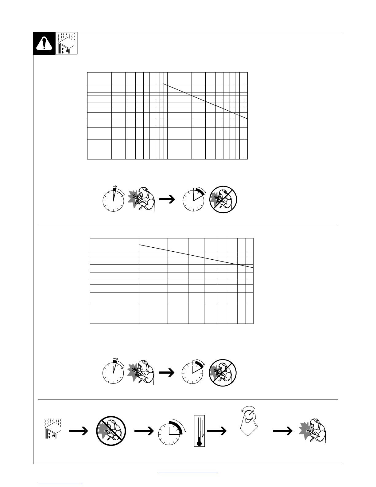
2-2. Duty Cycle And Overheating
C. 115 VAC Model
200
135
100
80
60
40
20
Output Amperes
Duty Cycle is percentage of 10 mi n utes that unit can weld at rated load
without overheating.
If unit overheats, thermostat(s)
opens, output stops, and cooling
fan runs. Wait fifteen minutes for
unit to cool. Reduce amperage or
duty cycle before welding.
Y Exceeding duty cycle can
damage unit or gun and void
warranty.
10
1
D. 230 VAC Model
200
130
100
80
60
40
Output Amperes
20
10
10
410
2
6808
20
40 60 100
Duty Cycle %
20% duty cycle at 90 amps
2 Minutes Welding 8 Minutes Resting
20
30
40 50
60 70 80 100
Duty Cycle %
3 Minutes Welding 7 Minutes Resting
Overheating
TM-944 Page 4 Handler 135 / 175
30% duty cycle at 130 amps, 60 Hz
20% duty cycle at 130 amps, 50 Hz
0
15
Minutes
Return To Table Of Contents
A or V
OR
Reduce Duty Cycle
duty1 4/95 − 196 617 / 196 618
Page 7

2-3. Volt-Ampere Curves
E. 115 VAC Model
30.0
25.0
20.0
15.0
OUTPUT VOLTS
10.0
5.0
0.0
0 10 20 30 40 50 60 70 80 90 100 110 120 130 140 150 160
The volt-ampere curves show the
minimum and maximum voltage
and amperage output capabilities of
the welding power source. Curves
of other settings fall between the
curves shown.
Range 4
Range 3
Range 2
Range 1
LOAD AMPS
F. 230 VAC Model
30.0
25.0
20.0
15.0
OUTPUT VOLTS
10.0
5.0
0.0
0 10 20 30 40 50 60 70 80 90 100 110 120 130 140 150 160 170 180 190 200
Range 4
Range 3
Range 2
Range 1
LOAD AMPS
Return To Table Of Contents
ssb1.1 10/91 − 196 608 / 196 609
TM-944 Page 5Handler 135 / 175
Page 8
SECTION 3 − INSTALLATION
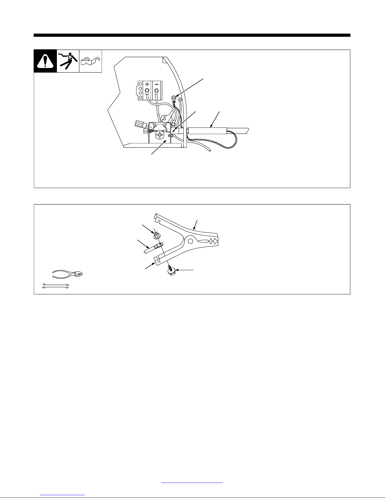
3-1. Installing Welding Gun
3-2. Installing Work Clamp
1 Drive Assembly
2 Gun Securing Thumbscrew
4
2
1
3
3 Gun End
Loosen thumbscrew. Insert gun
end through opening until it bottoms
against drive assembly. Tighten
thumbscrew.
4 Gun Trigger Leads
Insert leads, one at a time, through
gun opening on front panel.
Connect female friction terminals to
matching male terminals in unit.
Polarity is not important.
Close door.
Ref. 802 440-A
Tools Needed:
3/8, 7/16 in
3
1
2
5
4
1 Nut
2 Work Cable From Unit
3 Work Clamp
4 Screw
5 Work Clamp Tabs
Bend tabs around work cable.
802 456
TM-944 Page 6 Handler 135 / 175
Return To Table Of Contents
Page 9
3-3. Process/Polarity Table
Process
Polarity
GMAW − Solid wire with shielding gas
FCAW − Self-shielding wire −
no shielding gas
DCEP − Reverse polarity Connect to positive (+) out-
DCEN − Straight Polarity Connect to negative (−)
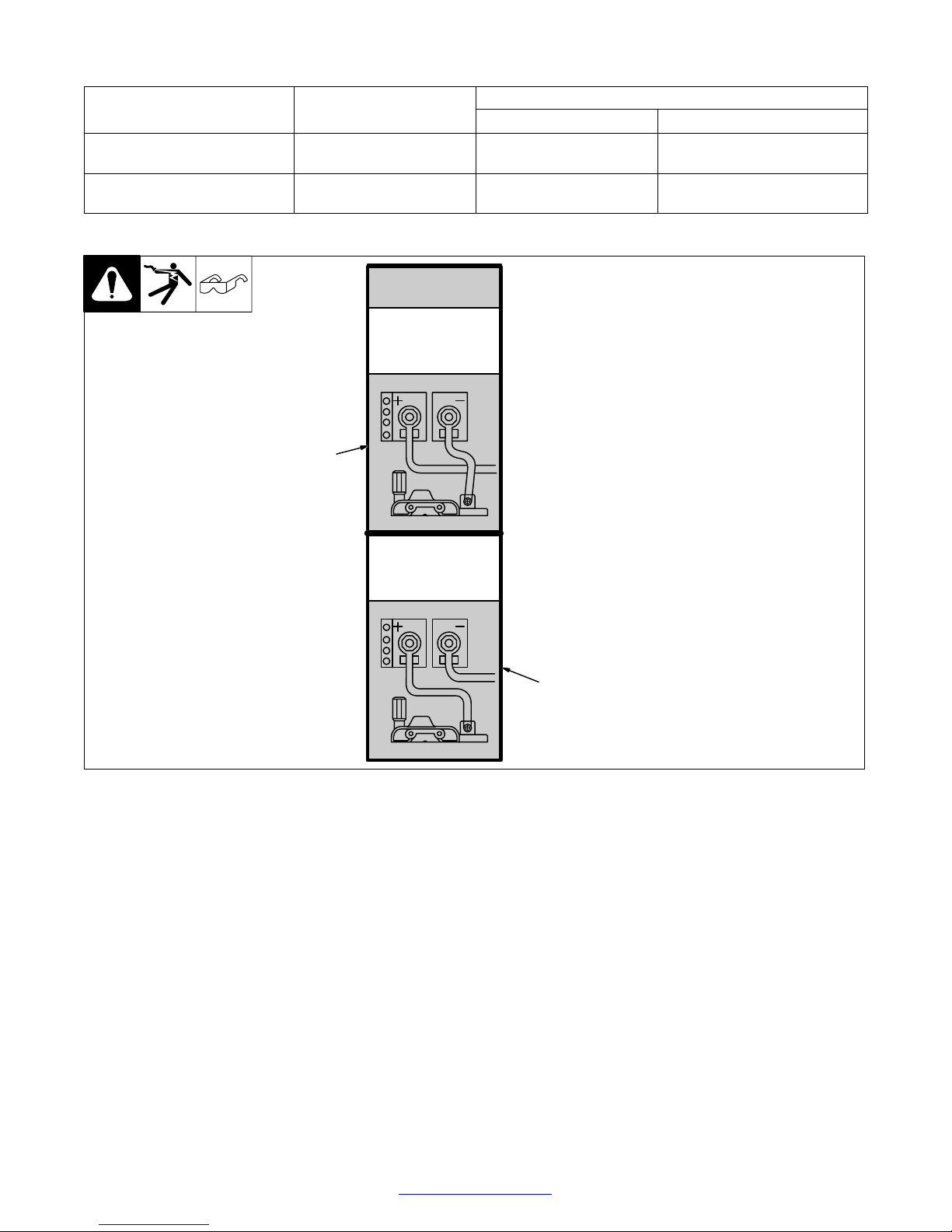
3-4. Changing Polarity
Cable Connections
Cable To Gun Cable To W ork
Connect to negative (−) output
put terminal
terminal
Connect to positive (+) output
output terminal
terminal
CHANGING
POLARITY
DCEN
Electrode Negative
For Flux Core Wire
1
DCEP
Electrode Positive
For Solid Wire
2
1 Lead Connections For Direct
Current Electrode Negative
(DCEN)
2 Lead Connections For Direct
Current Electrode Positive
(DCEP)
Always read and follow wire
manufacturer’s recommended polarity, and see Section 3-3.
Close door.
Return To Table Of Contents
Ref. 209 228 / Ref. 209 229
TM-944 Page 7Handler 135 / 175
Page 10
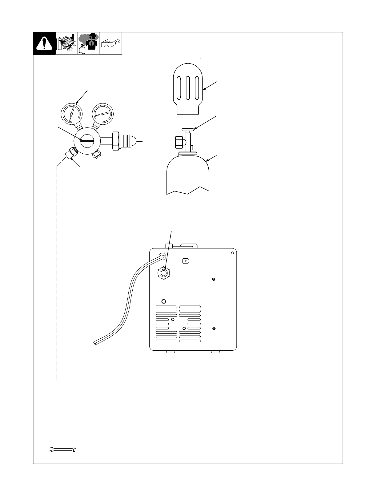
3-5. Installing Gas Supply
. DO NOT use Argon/Mixed gas regulator/flowmeter
with CO2 shielding gas. See Parts List for optional
CO2 gas regulator/flowmeter.
4
7
5
Argon Gas Or
Mixed Gas
Obtain gas cylinder and chain to
running gear, wall, or other
stationary support so cylinder
cannot fall and break off valve.
1 Cap
2 Cylinder Valve
1
2
3
Remove c ap, stand to side of valve,
and open valve slightly. Gas flow
blows dust and dirt from valve.
Close valve.
3 Cylinder
4 Regulator/Flowmeter
Install so face is vertical.
5 Regulator/Flowmeter Gas
Hose Connection
6 Welding Power Source Gas
Hose Connection
Connect customer supplied gas
hose between regulator/flowmeter
gas hose connection, and fitting on
rear of welding power source.
7 Flow Adjust
Typical flow rate is 20 cfh (cubic
feet per hour). Check wire
manufacturer’s rec o m m e n ded flow
rate.
6
Tools Needed:
5/8, 1-1/8 in
TM-944 Page 8 Handler 135 / 175
Ref. 802 028-A / 802 441
Return To Table Of Contents
Page 11
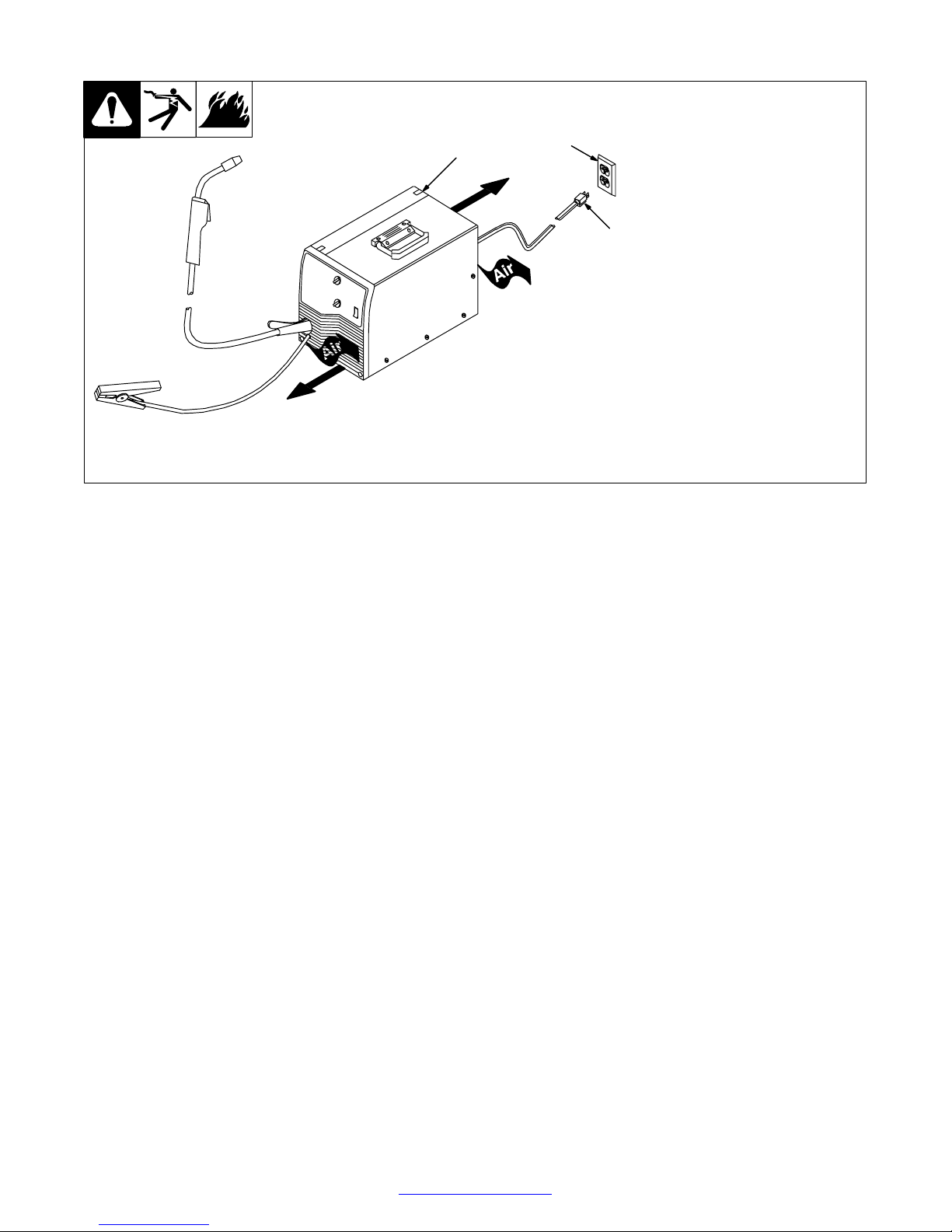
3-6. Selecting A Location And Connecting Input Power For 115 VAC Model
1 Rating Label
2 Grounded Receptacle
A 115 volt, 20 ampere individual
branch circuit protected by tim e- delay fuses or circuit breaker is required.
3 Plug From Unit
Select extension cord of 14 AWG
for up to 50 ft (15 m) or 12 AWG for
50 up to 200 ft (61 m).
Y Special installation may be
required where gasoline or
volatile liquids are present −
see NEC Article 511 or CEC
Section 2 0 .
18 in
(460 mm)
1
18 in
(460 mm)
2
3
802 442-A
Return To Table Of Contents
TM-944 Page 9Handler 135 / 175
Page 12
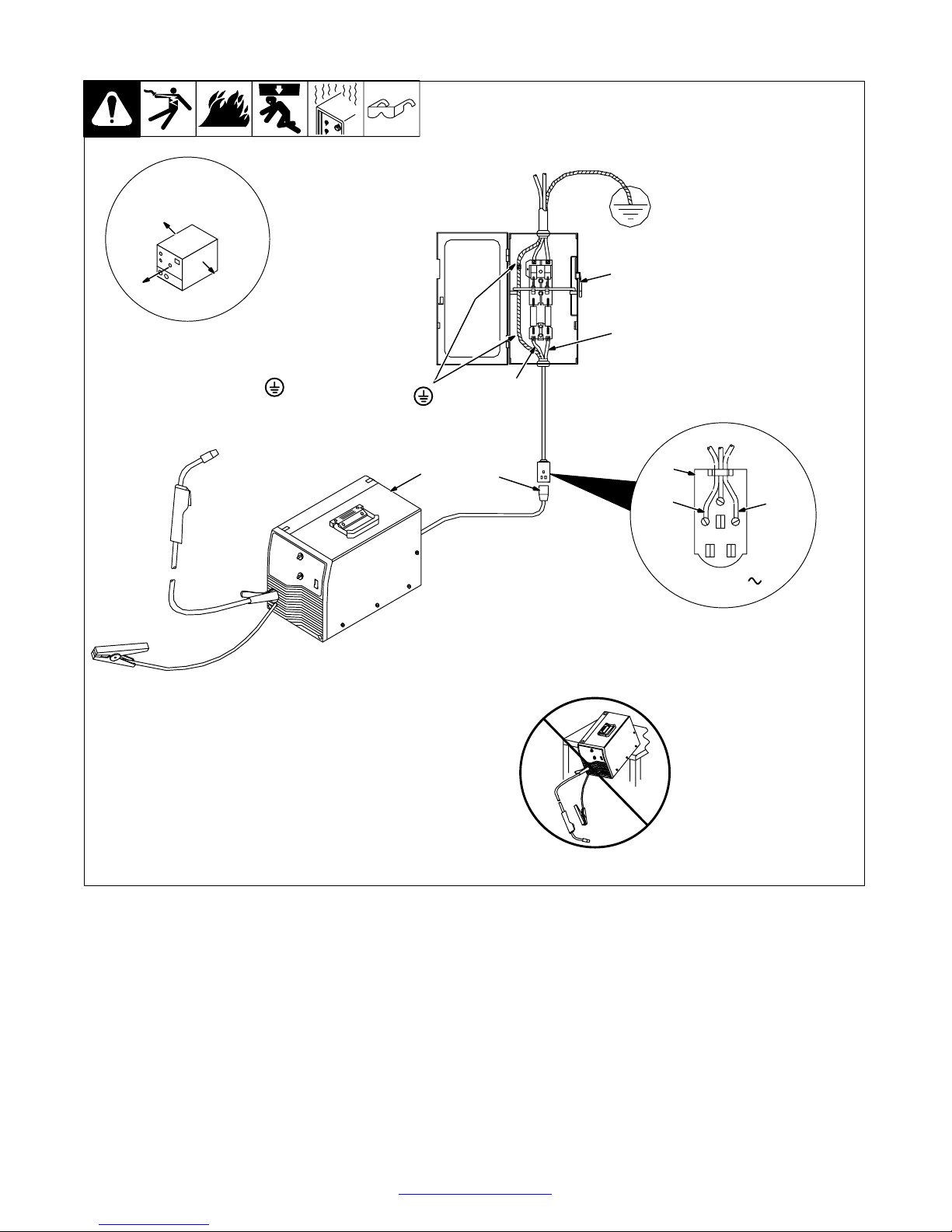
3-7. Selecting A Location And Connecting Input Power For 230 VAC Model
1 Rating Label
Supply correct input power.
2 Plug (NEMA 6-50P)
3 Receptacle (NEMA 6-50R)
Connect plug to receptacle.
18 in (457 mm) of
space for airflow
4
4 Line Disconnect Device
See Section 3-8.
Y Special installation may be
required where gasoline or
volatile liquids are present −
see NEC Article 511 or CEC
Section 2 0 .
Y Always connect
grounding
conductor first.
= GND/PE
Y Do not move or operate unit
where it could tip.
L1
L2
1
2
3
L2
230 VAC, 1
L1
TM-944 Page 10 Handler 135 / 175
ssb2.2* 1/94 − 802 443-A / Ref. 802 085
Return To Table Of Contents
Page 13
3-8. Electrical Service Guide For 230 VAC Model
Input Voltage
Input Amperes At Rated Output
Max Recommended Standard Fuse Or Circuit Breaker Rating In Amperes
Min Input Conductor Size In AWG/Kcmil
Max Recommended Input Conductor Length In Feet (Meters)
Min Grounding Conductor Size In AWG/Kcmil
Reference: 1996 National Electrical Code (NEC) S-0092-J
230
20
20
14
66 (20)
12
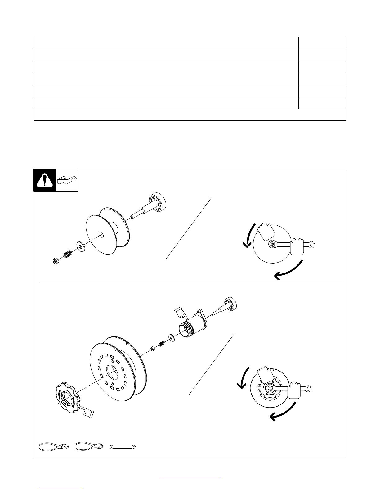
3-9. Installing Wire Spool And Adjusting Hub Tension
Installing 4 in (102 mm) Wire Spool
When a slight force is needed
to turn spool, tension is set.
Installing 8 in (203 mm) Wire Spool
Retaining ring used
with 8 in (203 mm)
spool only.
Tools Needed:
Adapter used with
8 in (203 mm)
spool only.
When a slight force is needed
to turn spool, tension is set.
1/2 in
803 012 / 803 013-B / Ref. 802 971-C
Return To Table Of Contents
TM-944 Page 11Handler 135 / 175
Page 14
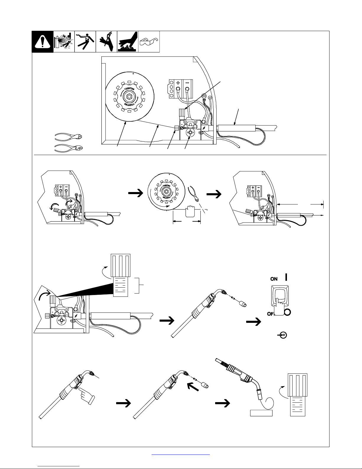
3-10. Threading Welding Wire
Tools Needed:
1 Wire Spool
2 Welding Wire
3 Inlet Wire Guide
4 Pressure Adjustment Knob
5 Drive Roll
6 Gun Conduit Cable
4
Lay gun cable out straight.
6
Open pressure assembly.
Tighten
1
2
3
5
. Hold wire tightly to keep it
from unraveling.
4 in
(102 mm)
6 in
(150 mm)
Pull and hold wire; cut off end.
Push wire thru guides into gun;
continue to hold wire.
. Use pressure indicator
scale to set a desired
drive roll pressure.
1
2
3
4
Pressure
Indicator
Scale
Be sure that wire is positioned
in proper feed roll groove.
Close and tighten pressure
assembly, and let go of wire.
Press gun trigger until wire comes
out of gun.
TM-944 Page 12 Handler 135 / 175
Remove gun nozzle and contact tip.
Be sure that tip matches wire diameter.
Reinstall contact tip and nozzle.
Return To Table Of Contents
INPUT
POWER
Turn power on.
Tighten
1
2
3
WOOD
Feed wire to check drive roll pressure.
Tighten knob enough to prevent slipping.
Cut off wire. Close door .
4
Ref. 802 444-C
Page 15
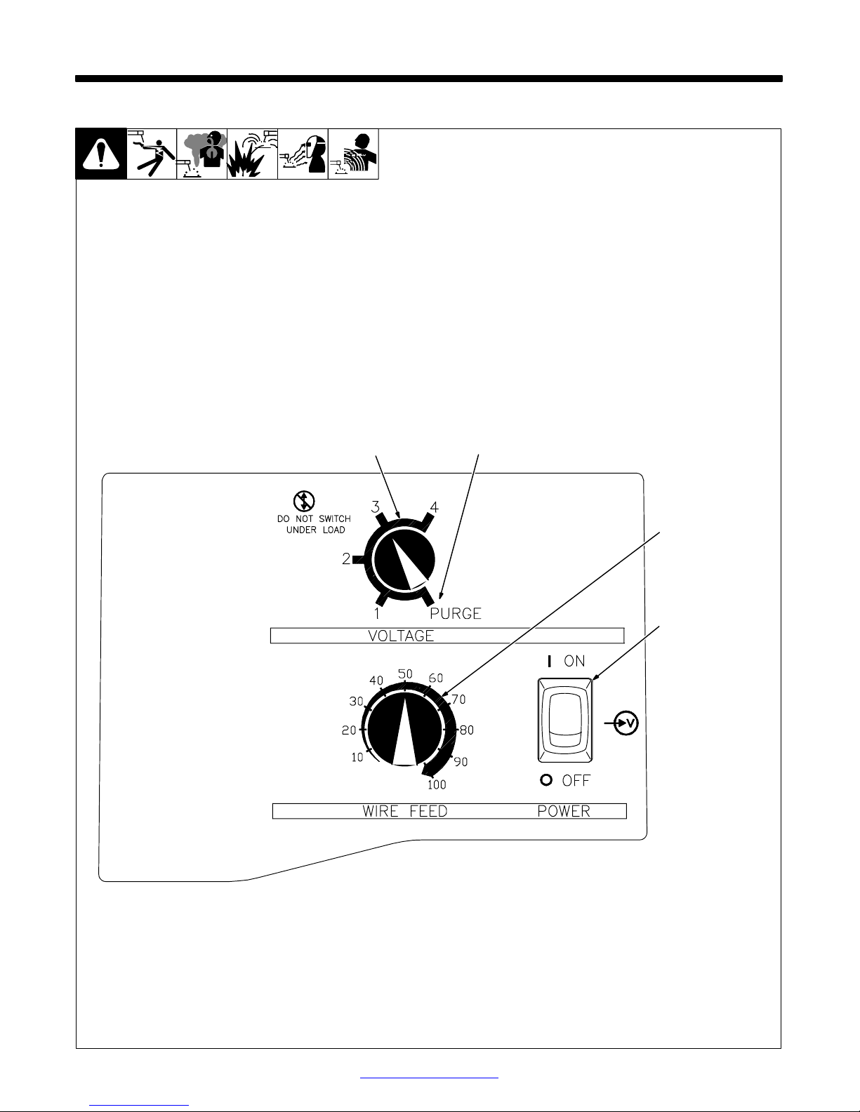
4-1. Controls
SECTION 4 − OPERATION
1
2
1 Voltage Switch
The higher the selected number,
the thicker the material that can be
welded (see weld setting label in
welding power source or Sections
4-2 and 4-3, as applicable). Do not
switch under load.
. Switch must “click” into detent
position 1, 2, 3, 4, or purge for
proper contact.
2 Voltage Switch - Purge “0”
Position
In purge position, fan runs but there
is no weld output.
3 Wire Speed Control
Use control to select a wire feed
speed. A s Voltage switch setting increases, wire speed range also increases (see weld setting label in
welding power source or Sections
4-2 or 4-3, as applicable).
4 Power Switch
3
4
Return To Table Of Contents
Ref. 196 082
TM-944 Page 13Handler 135 / 175
Page 16

4-2. Weld Parameter Chart For 115 VAC Model
Welding Guide
Settings are approximate. Adjust as required. Thicker materials can be welded
using proper technique, joint preparation, and multiple passes.
Material
Being
Welded
Steel
Stainless
Steel
Aluminum
Match feedroll groove to diameter of wire being used.
Set Tension Knob Setting to 3 at Start.
Adjust tension per instructions in the manual.
Wire Type,
and
Polarity Setting
Flux Core
E71T −11
(DCEN)
Solid Wire
ER70S−6
(DCEP)
Solid Wire
ER70S−6
(DCEP)
Stainless
Steel
(DCEP)
Aluminum**
(DCEP)
Suggested
Shielding Gas
20−30 cfh Flow Rate
No Shielding Gas Required
Good for Windy or
Outdoor Applications
C25 Gas Mixture
75% Argon / 25% CO2
Produces less Spatter
Appearance
Better
100% CO2
Tri−Mix
90% He/7.5% Ar/2.5% CO2
100% Argon**
Diameter
Wire
of
Being Used
.030” (0.8 mm)
.035” (0.9 mm)
.024” (0.6 mm)
.030” (0.8 mm)
.024” (0.6 mm)
.030” (0.8 mm)
.024” (0.6 mm)
.030” (0.8 mm)
.030” (0.8 mm)
CAUTION!
Do not change Voltage Switch
Knob position while welding.
**Aluminum wire is relatively soft so feedability is not as good. Make sure that hub tension is not too tight and
TM-944 Page 14 Handler 135 / 175
Return To Table Of Contents
Page 17

for 115 Volt Wire Welding Package
Recommended Voltage and Wire Speed Settings for Thickness of Metal Being Welded.
Number on Left of Slash is Voltage Setting / Number on Right of Slash is Wire Feed Setting.
22 gauge
(.8 mm)
−−−
−−−
1/10
−−−
−−−
−−−
−−−
−−−
−−−
18 gauge
(1.2 mm)
1/10
−−−
1/20
2/10
2/10
3/10
2/30
2/15
−−−
16 gauge
(1.6 mm)
1/20
1/10
2/30
3/30
2/15
4/10
3/40
3/10
−−−
1/8 inch
(3.2 mm)
3/30
3/10
4/65
4/50
4/40
4/20
4/50
4/30
4/90**
3/16 inch
(4.8 mm)
4/40
4/30
−−−
−−−
−−−
−−−
−−−
−−−
−−−
CHANGING
POLARITY
DCEN
Electrode Negative
For Flux Core Wire
DCEP
Electrode Positive
For Solid Wire
Wire Speed listed is a starting value only − Wire Speed setting can be
fine−tuned while welding. Wire Speed also depends on other variables
such as stick out, travel speed, weld angle, cleanliness of metal, etc.
keep torch as straight as possible. A ”push angle” for the torch is normally recommended.
Return To Table Of Contents
209 228
TM-944 Page 15Handler 135 / 175
Page 18

4-3. Weld Parameter Chart For 230 VAC Model
Welding Guide
Settings are approximate. Adjust as required. Thicker materials can be welded
using proper technique, joint preparation, and multiple passes.
Material
Being
Welded
Steel
Stainless
Steel
Aluminum
Match feedroll groove to diameter of wire being used.
Set Tension Knob Setting to 3 at Start.
Adjust tension per instructions in the manual.
Wire Type,
and
Polarity Setting
Flux Core
E71T −1 1
(DCEN)
Solid Wire
ER70S−6
(DCEP)
Solid Wire
ER70S−6
(DCEP)
Stainless
Steel
(DCEP)
Aluminum**
(DCEP)
Suggested
Shielding Gas
20−30 cfh Flow Rate
No Shielding Gas Required
Good for Windy or
Outdoor Applications
C25 Gas Mixture
75% Argon / 25% CO2
Produces less Spatter
Appearance
Better
100% CO2
Tri−Mix
90% He/7.5% Ar/2.5% CO2
100% Argon**
Diameter
of Wire
Being Used
.030” (0.8 mm)
.035” (0.9 mm)
.045” (1.2 mm)
.024” (0.6 mm)
.030” (0.8 mm)
.035” (0.9 mm)
.024” (0.6 mm)
.030” (0.8 mm)
.035” (0.9 mm)
.024” (0.6 mm)
.030” (0.8 mm)
.035” (0.9 mm)
.030” (0.8 mm)
.035” (0.9 mm)
CAUTION!
Do not change Voltage Switch
Knob position while welding.
**Aluminum wire is relatively soft so feedability is not as good. Make sure that hub tension is not too tight and
TM-944 Page 16 Handler 135 / 175
Return To Table Of Contents
Page 19

for 230 Volt Wire Welding Package
Recommended Voltage and Wire Speed Settings for Thickness of Metal Being Welded.
Number on Left of Slash is Voltage Setting / Number on Right of Slash is Wire Feed Setting.
22 gauge
(.8 mm)
−−−
−−−
−−−
1/20
1/10
−−−
1/10
−−−
−−−
−−−
−−−
−−−
−−−
−−−
18 gauge
(1.2 mm)
1/10
−−−
−−−
1/45
1/30
1/20
2/30
2/20
2/10
2/20
2/10
−−−
−−−
−−−
16 gauge
(1.6 mm)
1/30
1/20
−−−
2/85
2/40
2/30
2/35
2/30
2/20
2/40
2/20
2/10
1/100**
1/95**
1/8 inch
(3.2 mm)
3/50
3/40
2/20
3/90
3/80
3/75
3/70
3/65
3/40
3/50
2/40
2/30
4/100**
4/90**
3/16 inch
(4.8 mm)
3/60
3/50
3/40
4/100
4/85
3/80
4/85
4/40
4/30
4/90
4/80
4/70
−−−
−−−
1/4 inch
(6.4 mm)
4/80
4/60
4/50
−−−
4/100
4/70
−−−
4/50
4/40
−−−
−−−
−−−
−−−
−−−
CHANGING
POLARITY
DCEN
Electrode Negative
For Flux Core Wire
DCEP
Electrode Positive
For Solid Wire
Wire Speed listed is a starting value only − Wire Speed setting can be
fine−tuned while welding. Wire Speed also depends on other variables
such as stick out, travel speed, weld angle, cleanliness of metal, etc.
keep torch as straight as possible. A ”push angle” for the torch is normally recommended.
Return To Table Of Contents
209 229
TM-944 Page 17Handler 135 / 175
Page 20

1 Circuit Breaker CB1
SECTION 5 − THEORY OF OPERATION
Protects unit from an over-current
condition b y opening primary power
line.
2 Power Switch S1
Turns unit and fan motor FM on and
off.
3 Fan Motor FM And
Transformer
Controlled by power switch S1. Fan
cools internal components, and
transformer supplies control
voltage to PC1.
4 Thermostat TP1
If unit overheats, TP1 opens
stopping all weld output.
5 Gun Trigger Receptacle RC3
Connects gun trigger circuit to
welding power source.
6 Control Board PC1
Controls weld output by connecting
primary power to main transformer
T1 through a board-mounted
contactor that is activated by
pressing the gun trigger. PC1 also
regulates wire feed motor speed
with a motor control circuit. Speed
is set by feedback from Wire Feed
Speed Control R1.
7 Gas Valve GS1
Controls shielding gas flow.
Pressing gun trigger opens valve.
8 Wire Speed Control R1
Controls wire feed motor speed by
providing a reference voltage to
motor control circuit on PC1.
9 Range Switch S2
Allows selection of weld output
voltage.
10 Main Transformer T1
Supplies power to weld output
circuit.
11 Main Rectifier SR1
Changes the ac output from T1 to
full-wave rectified dc output.
12 Output Capacitor C1
Smooths d c weld voltage from main
rectifier SR1.
13 Stabilizer L1
Smooths d c weld current from main
rectifier SR1.
14 Polarity Changeover Block
Terminals allow changing between
DCEP and DCEN processes.
15 Wire Drive Motor
Feeds wire at a speed set by R1.
Pressing gun trigger activates wire
drive motor.
2
Power Switch
S1
1
Circuit
Breaker CB1
Line
L1
Single-Phase
Line Input
Power
Neutral Line
(115 VAC Model)
Line L2
(230 VAC Models)
34
Fan Motor FM
And Transformer
6
7
Gas Valve
GS1
Thermostat
TP1
Control Board
PC1
8
Wire Speed
Control R1
5
Gun Trigger
Receptacle RC3
TM-944 Page 18 Handler 135 / 175
Return To Table Of Contents
Page 21

9
Range Switch
S2
10
11
Main Rectifier
SR1
13
Stablizer L1
Main
Transformer
T1
12
Capacitor C1
14
Polarity
Changeover
Wire Drive
Block
Motor
15
Welding Wire
(Electrode)
Return To Table Of Contents
Work
AC Or DC Control Circuits
Weld Current Circuit
TM-944 Page 19Handler 135 / 175
Page 22

SECTION 6 − TROUBLESHOOTING
runs.
6-1. Troubleshooting Table
Trouble Remedy
No weld output; wire does not feed; fan
does not run.
Secure power cord plug PLG1 in receptacle (see Section 3-6 or 3-7).
Replace building line fuse or reset circuit breaker if open.
Place Power switch S1 in On position (see Section 4-1).
Reset power source circuit breaker if open (see Section 7-2).
.
See Section 6-2 or 6-3 for test points and values
and Section 9 for parts location.
No weld output; wire does not feed; fan
Electrode wire feeding stops during
welding.
Rotate Voltage switch S2 out of the Purge (gas only) position.
Thermostat TP1 open (overheating). Allow fan to run; the thermostat will close when the unit has
cooled (see Section 7-3).
Secure gun trigger leads to receptacle RC3 (see Section 3-1).
Check continuity of gun trigger leads. Repair or replace gun if necessary.
Check Wire Speed control R1 for proper connections and resistance; R1 is 55k ohms ±20%.
Replace R1 if necessary.
Check continuity of Voltage switch S2, and replace if necessary.
Check diodes in main rectifier SR1, and replace if necessary.
Check main transformer T1 for signs of winding failure. Check continuity across windings and check for
proper connections. Check secondary voltages. Replace T1 if necessary.
Check control board PC1 connections and voltages, and replace if necessary.
Check the setting of Voltage switch S2. Machine will not weld if voltage control is set between range
positions. Rotate switch until it “clicks” into a detent position.
Straighten gun cable and/or replace damaged parts (see Section 7-6).
Readjust drive roll pressure (see Section 3-10).
Change to proper groove (see Section 7-4).
Readjust wire reel hub tension (see Section 3-9).
Replace contact tip if blocked (see Section 7-5).
Clean or replace wire inlet guide or liner if dirty or plugged (see Section 7-4 and/or 7-6).
Replace drive roll or pressure bearing if worn or slipping (see Section 7-4).
Secure gun trigger leads in receptacle RC3 (see Section 3-1).
Check continuity of gun trigger leads. Repair or replace gun if necessary.
Check and clear any restrictions at drive assembly and liner (see Section 3-10 and/or 7-6).
Release gun trigger and allow gun and motor protection circuitry to reset.
Check T1 for signs of winding failure. Check continuity across each winding and check for proper
connections. Check secondary voltages. Replace T1 if necessary.
Check Control board PC1 and connections, and replace PC1 if necessary (see Section 6-4).
TM-944 Page 20 Handler 135 / 175
Return To Table Of Contents
Page 23

Trouble Remedy
No weld output; wire feeds. Connect work clamp to get good metal-to-metal contact.
Replace gun contact tip (see Section 7-5).
Check thumbscrew securing gun end to feedhead adapter and tighten if necessary.
Low weld output. Connect unit to proper input voltage or check for low line voltage.
Place Voltage switch S2 in desired position (see Section 4-1).
Low or erratic wire speed. Readjust weld parameter settings.
Change to correct size drive roll.
Readjust drive roll pressure.
Clean or replace wire inlet guide or liner if dirty or plugged (see Section 7-4 and/or 7-6).
Readjust wire reel hub tension.
Check voltage and connections of wire drive motor. Replace motor if necessary.
Improper or no shielding gas flow. Clean or replace gas hose.
Check shielding gas valve GS1 for proper coil voltage and connections. Check continuity of coil. Replace
GS1 if necessary.
Clear blockage in gun.
Return To Table Of Contents
TM-944 Page 21Handler 135 / 175
Page 24

6-2. Troubleshooting Circuit Diagram For Welding Power Source (115 VAC Model)
V1
R3
V8/R5
R1
R2
V4
V2
V3
V5
See also Section 6-4
for PC1 data
V6
R4
V7
V9/R6
V10
R7
R8
V11/R9
TM-944 Page 22 Handler 135 / 175
Test Equipment Needed:
Return To Table Of Contents
Page 25

Voltage Readings
a) Tolerance − ±10 % unless
specified
b) Wiring Diagram − see Section 8
V1 115 volts ac with power cord plugged in
V2 115 volts ac with Power switch S1 On
V3 24 volts ac with Power switch S1 On
V4 30 volts dc with Power switch S1 On
V5 27 volts dc with gun trigger pressed
V6 115 volts ac with gun trigger pressed
V7 115 volts ac with gun trigger pressed
V8, 15.5 volts ac with Voltage switch S2
V9 in position 1
17.0 volts ac with Voltage switch S2
in position 2
18.5 volts ac with Voltage switch S2
in position 3
20.5 volts ac with Voltage switch S2
in position 4
V10 20.5 volts dc with Voltage switch S2
in position 1
22.5 volts dc with Voltage switch S2
in position 2
25.0 volts dc with Voltage switch S2
in position 3
27.5 volts dc with Voltage switch S2
in position 4
V11 12 to 19 volts dc from min. to max. of
Wire Speed control R1 with
Voltage switch S2 in position 1
13 to 21 volts dc from min. to max. of
Wire Speed control R1 with
Voltage switch S2 in position 2
15 to 23 volts dc from min. to max. of
Wire Speed control R1 with
Voltage switch S2 in position 3
17 to 26 volts dc from min. to max. of
Wire Speed control R1 with
Voltage switch S2 in position 4
Resistance Values
a) Tolerance − ±10% unless specified
b) Turn Off unit and disconnect input
power before checking resistance
R1-R6 All values for T1 are less than 1 ohm
R7 Less than 1 ohm at minimum position of
Wire Speed control R1; 55k ohms at
maximum position of Wire Speed control R1
R8 Less than 1 ohm
R9 Less than 2 ohms with wire feed motor
disconnected from circuit
Wire Speed And Drive Motor RPM Feeding Wire*
Voltage
Wire Diameter
And Type
.030/.035 Solid
or Flux Core
*All tests done with .030-.035 liner in H-10 model 10 foot welding gun, smooth
groove drive roll.
Values are nominal depending on drive roll pressure and spool hub tension.
Switch S2
Position
1
2
3
4
Min.
RPM
50
60
70
80
Max.
RPM
155
170
190
215
Min.
IPM
190
230
265
300
Drive Motor RPM At No Load*
Voltage
Switch S2
Position
Min.
RPM
Max.
RPM
Max.
IPM
585
640
715
800
1
2
3
4
*All tests done with the pressure assembly
open, not feeding wire. Values are nominal.
Return To Table Of Contents
95
110
125
140
170
180
200
225
194 324-C
TM-944 Page 23Handler 135 / 175
Page 26

6-3. Troubleshooting Circuit Diagram For Welding Power Source (230 VAC Model)
V1
R3
V8/R5
R1
R2
V4
V2
V3
V5
See also Section 6-6
for PC1 data
V6
R4
V7
V9/R6
V10
R7
R8
V11/R9
TM-944 Page 24 Handler 135 / 175
Test Equipment Needed:
Return To Table Of Contents
Page 27

Voltage Readings
a) Tolerance − ±10 % unless
specified
b) Wiring Diagram − see Section 8
V1 230 volts ac with power cord plugged in
V2 230 volts ac with Power switch S1 On
V3 24 volts ac with Power switch S1 On
V4 30 volts dc with Power switch S1 On
V5 27 volts dc with gun trigger pressed
V6 230 volts ac with gun trigger pressed
V7 230 volts ac with gun trigger pressed
V8, 13.9 volts ac with Voltage switch S2
V9 in position 1
16.5 volts ac with Voltage switch S2
in position 2
19.1 volts ac with Voltage switch S2
in position 3
21.7 volts ac with Voltage switch S2
in position 4
V10 18.9 volts dc with Voltage switch S2
in position 1
22.6 volts dc with Voltage switch S2
in position 2
25.1 volts dc with Voltage switch S2
in position 3
29.8 volts dc with Voltage switch S2
in position 4
V11 7.0 to 17.5 volts dc from min. to max. of
Wire Speed control R1 with
Voltage switch S2 in position 1
10.0 t o 20.5 volts dc from min. to max. of
Wire Speed control R1 with
Voltage switch S2 in position 2
12.7 t o 24.0 volts dc from min. to max. of
Wire Speed control R1 with
Voltage switch S2 in position 3
15.5 t o 27.0 volts dc from min. to max. of
Wire Speed control R1 with
Voltage switch S2 in position 4
Resistance Values
a) Tolerance − ±10% unless specified
b) Turn Off unit and disconnect input
power before checking resistance
R1-R6 All values for T1 are less than 1 ohm
R7 Less than 1 ohm at minimum position of
Wire Speed control R1; 55k ohms at
maximum position of Wire Speed control R1
R8 Less than 1 ohm
R9 Less than 2 ohms with wire feed motor
disconnected from circuit
Wire Speed And Drive Motor RPM Feeding Wire*
Voltage
Wire Diameter
And Type
.030/.035 Solid
or Flux Core
*All tests done with .030-.035 liner in H-10 model 10 foot welding gun, smooth
groove drive roll.
Values are nominal depending on drive roll pressure and spool hub tension.
Switch S2
Position
1
2
3
4
Min.
RPM
40
50
70
90
Max.
RPM
135
160
190
205
Min.
IPM
150
190
260
340
Drive Motor RPM At No Load*
Voltage
Switch S2
Position
Min.
RPM
Max.
RPM
Max.
IPM
510
600
700
800
1
2
3
4
*All tests done with the pressure assembly
open, not feeding wire. Values are nominal.
Return To Table Of Contents
80
110
135
160
150
175
200
235
194 325-A
TM-944 Page 25Handler 135 / 175
Page 28

6-4. Control Board PC1 Testing Information (115 VAC Model)
Be sure plugs are secure before
testing. See Section 6-5 for specific
values during testing.
1 Control Board PC1
2 Receptacle RC1
3 Receptacle RC2
4 Receptacle RC4
5 Receptacle RC5
6 TP-A
7 TP-B
8 TP-C
9 TP-D
10 TP-E
11 TP-F
1
2
6
78910 11
345
Test Equipment Needed:
802 779 / 195 888-B
TM-944 Page 26 Handler 135 / 175
Return To Table Of Contents
Page 29

6-5. Control Board PC1 Test Point Values (115 VAC Model)
a) Tolerance −
±10% unless
specified
PC1 Voltage Readings
b) Reference − to circuit common
unless noted
Voltage Readings:
a) Tolerance − ±10% unless specified b) Reference − as noted
Receptacle Pin Value
RC1 1 24 volts ac input, reference to pin RC1-2
2 24 volts ac input, reference to pin RC1-1
3,4 35 volts dc with transformer thermostat closed, reference to pin TP-C
5 35 volts dc with gun trigger closed, reference to TP-C
6 35 volts dc, reference to TP-C
7 15.0 volts dc, reference to TP-C
8 15.0 to 6.5 volts dc from min to max of Wire Feed speed control R1, Reference for TP-C
RC2
RC4 −− Circuit common
RC5 −− Positive (+) welder output voltage with gun trigger closed
TP A 35 volts dc, reference to TP-C
TP B 15 volts dc, reference to TP-C
TP C Circuit common
TP D 30 volts dc, reference to TP-C
TP E 15 volts dc with Wire Speed control R1 at minimum, reference to TP-C
TP F 11 volts dc with Wire Speed control R1 at maximum, reference to TP-C
1 Negative (−) welder output voltage
2 Not used
3 Positive (+) output to wire drive motor
4 Negative (−) output to wire drive motor
Return To Table Of Contents
TM-944 Page 27Handler 135 / 175
Page 30

6-6. Control Board PC1 Testing Information (230 VAC Model)
Be sure plugs are secure before
testing. See Section 6-7 for specific
values during testing.
1 Control Board PC1
2 Receptacle RC1
3 Receptacle RC2
4 Receptacle RC4
5 Receptacle RC5
6 TP-A
7 TP-B
8 TP-C
9 TP-D
10 TP-E
11 TP-F
1
5
2
6
78910 11
34
Test Equipment Needed:
802 779 / 195 889-B
TM-944 Page 28 Handler 135 / 175
Return To Table Of Contents
Page 31

6-7. Control Board PC1 Test Point Values (230 VAC Model)
a) Tolerance −
±10% unless
specified
PC1 Voltage Readings
b) Reference − to circuit common
unless noted
Voltage Readings:
a) Tolerance − ±10% unless specified b) Reference − as noted
Receptacle Pin Value
RC1 1 24 volts ac input, reference to pin RC1-2
2 24 volts ac input, reference to pin RC1-1
3,4 35 volts dc with transformer thermostat closed, reference to pin TP-C
5 35 volts dc with gun trigger closed, reference to TP-C
6 35 volts dc, reference to TP-C
7 15.0 volts dc, reference to TP-C
8 15.0 to 6.5 volts dc from min to max of Wire Feed speed control R1, Reference for TP-C
RC2
RC4 −− Circuit common
RC5 −− Positive (+) welder output voltage with gun trigger closed
TP A 35 volts dc, reference to TP-C
TP B 15 volts dc, reference to TP-C
TP C Circuit common
TP D 30 volts dc, reference to TP-C
TP E 15 volts dc with Wire Speed control R1 at minimum, reference to TP-C
TP F 11 volts dc with Wire Speed control R1 at maximum, reference to TP-C
1 Negative (−) welder output voltage
2 Not used
3 Positive (+) output to wire drive motor
4 Negative (−) output to wire drive motor
Return To Table Of Contents
TM-944 Page 29Handler 135 / 175
Page 32

SECTION 7 − MAINTENANCE
7-1. Routine Maintenance
Y Disconnect power before maintaining.
3 Months
Replace
unreadable
labels.
6 Months
Blow out or
vacuum inside.
During heavy
service, clean
monthly.
Or
7-2. Overload Protection
Repair or
replace
cracked
weld cable.
1
Clean and
tighten weld
terminals.
1 Circuit Breaker CB1
CB1 protects unit from overload. If
CB1 opens, unit shuts down.
Reset breaker.
7-3. Drive Motor Protection
Drive motor protection circuit protects drive motor from overload. If drive motor becomes inoperative, release gun
trigger and wait until protection circuit resets allowing drive motor to feed wire again.
TM-944 Page 30 Handler 135 / 175
802 441
Return To Table Of Contents
Page 33

7-4. Changing Drive Roll Or Wire Inlet Guide
1
2
Tools Needed:
4
.024 Groove.030/.035 Groove
1 Inlet Wire Gui d e S e c u r i n g
Screw
2 Inlet Wire Guide
Loosen screw. Slide tip as close t o
drive rolls as possible without
touching. Tighten screw.
3 Drive Roll
3
The drive roll consists of two different sized grooves. The stamped
markings on the end surface of the
drive roll refers to the groove on t he
opposite side of the drive roll. The
groove closest to the motor shaft is
the proper groove to thread (see
Section 3-10).
4 Retaining Pin
To secure drive roll, locate open slot
and push drive roll completely over
retaining pin, then rotate drive roll
(1/4 turn) to closed slot.
Stamped .024
7-5. Replacing Gun Contact Tip
Stamped .030/.035
Ref. 802 444-B
Y Turn Off power before
replacing contact tip.
1 Nozzle
2 Contact Tip
Cut off welding wire at contact tip.
Remove nozzle.
Remove contact tip and install new
contact tip. Reinstall nozzle.
Tools Needed:
2
1
Return To Table Of Contents
Ref. 802 399-A
TM-944 Page 31Handler 135 / 175
Page 34

7-6. Cleaning Or Replacing Gun Liner
Y Disconnect gun from unit.
Remove nozzle, contact tip,
adapter, gas diffuser, and wire
Head Tube
8 mm
outlet guide.
Tools Needed:
8 mm / 10mm
10 mm
Lay gun cable out straight
before installing new liner.
Blow out gun casing.
Remove liner.
To Reassemble Gun:
Insert new liner.
Install wire outlet guide so that 1/8
in (3 mm) of liner sticks out. Hand
tighten outlet guide, and then tighten two full turns more.
Cut liner off so that 3/4 in (19 mm)
sticks out of head tube.
Install g a s d i ffuser, adapter , contact
tip, and nozzle.
TM-944 Page 32 Handler 135 / 175
Ref. 802 446
Return To Table Of Contents
Page 35

7-7. Replacing Switch And/Or Head Tube
1
Remove handle
locking nut.
4
Secure head
tube in vice.
Y Turn Off welding power source
/wire feeder and disconnect gun.
3
Slide handle.
2
Remove switch housing. Install new switch and
connect leads (polarity is not important). Reassemble in reverse order. If replacing head tube,
continue t o end of figure.
6
Tools Needed:
5
Loosen jam nut.
Remove from vice
and turn head tube
out by hand.
Hand-tighten head tube into cable connector.
8
Remove from vice. Reposition handle and install
switch housing. Secure with handle locking nut.
7
Place head tube in vice and tighten until
nuts are tight.
19 mm
Return To Table Of Contents
Ref. ST-800 795-C
TM-944 Page 33Handler 135 / 175
Page 36

SECTION 8 − ELECTRICAL DIAGRAMS
. The circuits in this manual can be used for troubleshooting, but there might be minor circuit differences from your machine. Use circuit inside
machine case or contact your distributor for further information.
Model Serial Or Style Number Circuit Diagram Wiring Diagram
115 VAC Model KK213350 and following 194 324-C 196 637-A
230 VAC Model KK213350 and following 194 325-A 196 655-A
Circuit Board PC1
( 115 VAC Model)
Circuit Board PC1
(230 VAC Model)
KK213350 and following 195 890
KK213350 and following 195 891
TM-944 Page 34 Handler 135 / 175
Return To Table Of Contents
Page 37

Figure 8-1. Circuit Diagram For 115 VAC Model Effective With Serial No. KK213350 And Following
Return To Table Of Contents
194 324-C
TM-944 Page 35Handler 135 / 175
Page 38

Figure 8-2. Circuit Diagram For 230 VAC Model Effective With Serial No. KK213350 And Following
TM-944 Page 36 Handler 135 / 175
194 325-A
Return To Table Of Contents
Page 39

Figure 8-3. Wiring Diagram For 115 VAC Model Effective With Serial No. KK213350 And Following
Return To Table Of Contents
196 637-A
TM-944 Page 37Handler 135 / 175
Page 40

Figure 8-4. Wiring Diagram For 230 Model Effective With Serial No. KK213350 And Following
TM-944 Page 38 Handler 135 / 175
196 655-A
Return To Table Of Contents
Page 41

Figure 8-5. Circuit Diagram For 115 VAC Model Control Board PC1
Effective With Serial No. KK213350 And Following
Return To Table Of Contents
195 890-A
TM-944 Page 39Handler 135 / 175
Page 42

Figure 8-6. Circuit Diagram For 230 VAC Model Control Board PC1
Effective With Serial No. KK213350 And Following
TM-944 Page 40 Handler 135 / 175
195 891-A
Return To Table Of Contents
Page 43

TM-944C October 2003
Handler 135 (500 414) Eff. w/Serial No.
LB096205
Handler 175 (500 416) Eff. w/Serial No.
LB075197
Processes
MIG (GMAW) Welding
Flux Cored (FCAW) W elding
Description
Arc Welding Power Source And
Wire Feeder
Handler 135 / 175
And H-10 Gun
Visit our website at
www.HobartWelders.com
Page 44

13
12
SECTION 9 − PARTS LIST
. Hardware is common and
22
21
20
14
11
10
9
15
16
17
18
19
26
27
not available unless listed.
23
24
25
29
8
7
6
5
4
3
35
32
31
47
52
34
50
33
49
48
51
2
1
46
36
30
45
28
44
37
43
38
40
39
41
42
TM-944 Page 42 Handler 135 / 175
802 449-E
Figure 9-1. Main Assembly
Return To Table Of Contents
Page 45

Part
Dia.
Item
No.
ty
Mkgs.
No.
Description
Quanti
Figure 9-1. Main Assembly
1 199 566 DOOR, access 1. . . . . . . . . . . . . . . . . . . . . . . . . . . . . . . . . . . . . . . . . . . . . . . . . . . . . . . . . . . . . . . . . . . . .
2 196 006 HINGE, door 2. . . . . . . . . . . . . . . . . . . . . . . . . . . . . . . . . . . . . . . . . . . . . . . . . . . . . . . . . . . . . . . . . . . . . .
3 211 887 HUB, nut 1. . . . . . . . . . . . . . . . . . . . . . . . . . . . . . . . . . . . . . . . . . . . . . . . . . . . . . . . . . . . . . . . . . . . . . . . . .
4 204 608 NUT 1. . . . . . . . . . . . . . . . . . . . . . . . . . . . . . . . . . . . . . . . . . . . . . . . . . . . . . . . . . . . . . . . . . . . . . . . . . . . . .
5 202 998 SPRING, cprsn 1. . . . . . . . . . . . . . . . . . . . . . . . . . . . . . . . . . . . . . . . . . . . . . . . . . . . . . . . . . . . . . . . . . . .
6 203 072 WASHER, flat 1. . . . . . . . . . . . . . . . . . . . . . . . . . . . . . . . . . . . . . . . . . . . . . . . . . . . . . . . . . . . . . . . . . . . .
7 211 339 HUB, spool 1. . . . . . . . . . . . . . . . . . . . . . . . . . . . . . . . . . . . . . . . . . . . . . . . . . . . . . . . . . . . . . . . . . . . . . . .
8 202 726 ADAPTER, spool hub 1. . . . . . . . . . . . . . . . . . . . . . . . . . . . . . . . . . . . . . . . . . . . . . . . . . . . . . . . . . . . . . .
9 195 886 CIRCUIT CARD ASSY, control (115 VAC model) 1. . . . . . . . . . . . . . . . . . . . . . . . . . . . . . . . . . . . . . .
9 195 887 CIRCUIT CARD ASSY, control (230 VAC model) 1. . . . . . . . . . . . . . . . . . . . . . . . . . . . . . . . . . . . . . .
10 195 999 BASE, lower 1. . . . . . . . . . . . . . . . . . . . . . . . . . . . . . . . . . . . . . . . . . . . . . . . . . . . . . . . . . . . . . . . . . . . . . .
11 210 109 CIRCUIT BREAKER, 25 amp 1. . . . . . . . . . . . . . . . . . . . . . . . . . . . . . . . . . . . . . . . . . . . . . . . . . . . . . . .
12 196 467 TUBING, PVC .187 ID x .312 OD x 24.000 1. . . . . . . . . . . . . . . . . . . . . . . . . . . . . . . . . . . . . . . . . . . .
13 116 996 VALVE, gas (115 VAC model) 1. . . . . . . . . . . . . . . . . . . . . . . . . . . . . . . . . . . . . . . . . . . . . . . . . . . . . . . .
13 128 751 VALVE, gas (230 VAC model) 1. . . . . . . . . . . . . . . . . . . . . . . . . . . . . . . . . . . . . . . . . . . . . . . . . . . . . . . .
14 197 198 CABLE TIE, .700-.799 bundle dia 2. . . . . . . . . . . . . . . . . . . . . . . . . . . . . . . . . . . . . . . . . . . . . . . . . . . .
15 147 545 CORD SET, 125V 5−15P 14GA 3/C 7ft SPT−3 jkt (115 VAC model) 1. . . . . . . . . . . . . . . . . . . . . . .
15 152 118 CORD SET, 250V 6−50P 12GA 3/C 7ft SPT−3 jkt (230 VAC model) 1. . . . . . . . . . . . . . . . . . . . . . .
16 111 443 BUSHING, strain relief 1. . . . . . . . . . . . . . . . . . . . . . . . . . . . . . . . . . . . . . . . . . . . . . . . . . . . . . . . . . . . . .
17 605 227 NUT, gas valve 1. . . . . . . . . . . . . . . . . . . . . . . . . . . . . . . . . . . . . . . . . . . . . . . . . . . . . . . . . . . . . . . . . . . .
18 196 063 MOTOR, fan (115 VAC model) 1. . . . . . . . . . . . . . . . . . . . . . . . . . . . . . . . . . . . . . . . . . . . . . . . . . . . . . .
18 196 064 MOTOR, fan (230 VAC model) 1. . . . . . . . . . . . . . . . . . . . . . . . . . . . . . . . . . . . . . . . . . . . . . . . . . . . . . .
19 409 953-001 BLADE, fan cooling 1. . . . . . . . . . . . . . . . . . . . . . . . . . . . . . . . . . . . . . . . . . . . . . . . . . . . . . . . . . . . .
20 194 268 TRANSFORMER, power assy (115 VAC model) 1. . . . . . . . . . . . . . . . . . . . . . . . . . . . . . . . . . . . . . . .
20 194 277 TRANSFORMER, power assy (230 VAC model) 1. . . . . . . . . . . . . . . . . . . . . . . . . . . . . . . . . . . . . . . .
21 208 015 HANDLE, carrying 1. . . . . . . . . . . . . . . . . . . . . . . . . . . . . . . . . . . . . . . . . . . . . . . . . . . . . . . . . . . . . . . . . .
22 196 005 WRAPPER 1. . . . . . . . . . . . . . . . . . . . . . . . . . . . . . . . . . . . . . . . . . . . . . . . . . . . . . . . . . . . . . . . . . . . . . . .
23 204 036 LABEL, warning 1. . . . . . . . . . . . . . . . . . . . . . . . . . . . . . . . . . . . . . . . . . . . . . . . . . . . . . . . . . . . . . . . . . . .
24 203 491 CLAMP, capacitor 1. . . . . . . . . . . . . . . . . . . . . . . . . . . . . . . . . . . . . . . . . . . . . . . . . . . . . . . . . . . . . . . . . .
25 193 039 CAPACITOR, electlt 53000uf (115 VAC model) 1. . . . . . . . . . . . . . . . . . . . . . . . . . . . . . . . . . . . . . . . .
25 193 040 CAPACITOR, electrlt 100000uf (230 VAC model) 1. . . . . . . . . . . . . . . . . . . . . . . . . . . . . . . . . . . . . . .
26 203 868 REACTOR ASSY (115 VAC model) 1. . . . . . . . . . . . . . . . . . . . . . . . . . . . . . . . . . . . . . . . . . . . . . . . . . .
26 203 874 REACTOR ASSY (230 VAC model) 1. . . . . . . . . . . . . . . . . . . . . . . . . . . . . . . . . . . . . . . . . . . . . . . . . . .
27 193 191 RECTIFIER ASSY (115 VAC model) 1. . . . . . . . . . . . . . . . . . . . . . . . . . . . . . . . . . . . . . . . . . . . . . . . . .
27 193 316 RECTIFIER ASSY (230 VAC model) 1. . . . . . . . . . . . . . . . . . . . . . . . . . . . . . . . . . . . . . . . . . . . . . . . . .
28 198 585 PLATE, support (230 VAC model only) 1. . . . . . . . . . . . . . . . . . . . . . . . . . . . . . . . . . . . . . . . . . . . . . . .
203 390 KEY, woodruff l (115 VAC model Prior to LC175022 or. . . . . . . . . . . . . . . . . . . . . . .
230 VAC model Prior to LC155844) 1. . . . . . . . . . . . . . . . . . . . . . . . . . . . . . .
29 193 193 BUS BAR (positive) 1. . . . . . . . . . . . . . . . . . . . . . . . . . . . . . . . . . . . . . . . . . . . . . . . . . . . . . . . . . . . . . . .
30 196 000 BAFFLE, center 1. . . . . . . . . . . . . . . . . . . . . . . . . . . . . . . . . . . . . . . . . . . . . . . . . . . . . . . . . . . . . . . . . . . .
31 405 576-001 BUSHING, terminal 1. . . . . . . . . . . . . . . . . . . . . . . . . . . . . . . . . . . . . . . . . . . . . . . . . . . . . . . . . . . . .
32 193 144 INSULATOR, output stud 1. . . . . . . . . . . . . . . . . . . . . . . . . . . . . . . . . . . . . . . . . . . . . . . . . . . . . . . . . . . .
33 193 194 BUS BAR (negative) 1. . . . . . . . . . . . . . . . . . . . . . . . . . . . . . . . . . . . . . . . . . . . . . . . . . . . . . . . . . . . . . . .
34 199 824 LABEL, warning 1. . . . . . . . . . . . . . . . . . . . . . . . . . . . . . . . . . . . . . . . . . . . . . . . . . . . . . . . . . . . . . . . . . . .
35 134 201 STAND-OFF 1. . . . . . . . . . . . . . . . . . . . . . . . . . . . . . . . . . . . . . . . . . . . . . . . . . . . . . . . . . . . . . . . . . . . . . .
36 409 477 SWITCH, rotary 25A 5 position 1. . . . . . . . . . . . . . . . . . . . . . . . . . . . . . . . . . . . . . . . . . . . . . . . . . . . . . .
37 194 513 POTENTIOMETER, 1. . . . . . . . . . . . . . . . . . . . . . . . . . . . . . . . . . . . . . . . . . . . . . . . . . . . . . . . . . . . . . . .
38 196 129 PANEL, front (purple) 1. . . . . . . . . . . . . . . . . . . . . . . . . . . . . . . . . . . . . . . . . . . . . . . . . . . . . . . . . . . . . . .
38 196 007 PANEL, front (black) 1. . . . . . . . . . . . . . . . . . . . . . . . . . . . . . . . . . . . . . . . . . . . . . . . . . . . . . . . . . . . . . . .
39 010368 CLAMP, work 1. . . . . . . . . . . . . . . . . . . . . . . . . . . . . . . . . . . . . . . . . . . . . . . . . . . . . . . . . . . . . . . . . . . . . .
40 196 619 CABLE, work 1. . . . . . . . . . . . . . . . . . . . . . . . . . . . . . . . . . . . . . . . . . . . . . . . . . . . . . . . . . . . . . . . . . . . . .
41 196 575 SWITCH, rocker SPST (115 VAC model) 1. . . . . . . . . . . . . . . . . . . . . . . . . . . . . . . . . . . . . . . . . . . . . .
Return To Table Of Contents
TM-944 Page 43Handler 135 / 175
Page 46

Part
Dia.
Item
No.
ty
Mkgs.
No.
Description
Quanti
Figure 9-1. Main Assembly (Continued)
41 196 574 SWITCH, rocker DPST (230 VAC model) 1. . . . . . . . . . . . . . . . . . . . . . . . . . . . . . . . . . . . . . . . . . . . . .
42 207 078 KNOB, pointer (WFS) 1. . . . . . . . . . . . . . . . . . . . . . . . . . . . . . . . . . . . . . . . . . . . . . . . . . . . . . . . . . . . . . .
43 207 079 KNOB, pointer (voltage) 1. . . . . . . . . . . . . . . . . . . . . . . . . . . . . . . . . . . . . . . . . . . . . . . . . . . . . . . . . . . . .
44 193 187 MOTOR, gear (115 VAC model Prior to LC175022 or. . . . . . . . . . . . . . . . . . . .
230 VAC model Prior to LC155844) 1. . . . . . . . . . . . . . . . . . . . . . . . . . . . . . .
44 202 708 MOTOR, gear (115 VAC model Eff w/LC175022 or. . . . . . . . . . . . . . . . . . . .
230 VAC model w/ LC155844) 1. . . . . . . . . . . . . . . . . . . . . . . . . . . . . . . . . . .
45 193 189 CONNECTOR, gun 1. . . . . . . . . . . . . . . . . . . . . . . . . . . . . . . . . . . . . . . . . . . . . . . . . . . . . . . . . . . . . . . . .
46 196 654 SCREW, thumb 1. . . . . . . . . . . . . . . . . . . . . . . . . . . . . . . . . . . . . . . . . . . . . . . . . . . . . . . . . . . . . . . . . . . .
203 081 SCREW, feed roll (115 VAC model Prior to LC175022 or. . . . . . . . . . . . . . . . . . . . . . .
230 VAC model Prior to LC155844) 1. . . . . . . . . . . . . . . . . . . . . . . . . . . . . . .
47 196 009 FITTING, gas barbed 1. . . . . . . . . . . . . . . . . . . . . . . . . . . . . . . . . . . . . . . . . . . . . . . . . . . . . . . . . . . . . . .
48 202 925 ROLL, feed .024 in, .030/.035 in 1. . . . . . . . . . . . . . . . . . . . . . . . . . . . . . . . . . . . . . . . . . . . . . . . . . . . . .
49 194 508 HEAD, feed assy 1. . . . . . . . . . . . . . . . . . . . . . . . . . . . . . . . . . . . . . . . . . . . . . . . . . . . . . . . . . . . . . . . . . .
50 203 025 GUIDE, wire inlet 1. . . . . . . . . . . . . . . . . . . . . . . . . . . . . . . . . . . . . . . . . . . . . . . . . . . . . . . . . . . . . . . . . . .
51 209 228 LABEL, weld chart (115 VAC model) 1. . . . . . . . . . . . . . . . . . . . . . . . . . . . . . . . . . . . . . . . . . . . . . . . . .
51 209 229 LABEL, weld chart (230 VAC model) 1. . . . . . . . . . . . . . . . . . . . . . . . . . . . . . . . . . . . . . . . . . . . . . . . . .
52 204 711 LATCH 1. . . . . . . . . . . . . . . . . . . . . . . . . . . . . . . . . . . . . . . . . . . . . . . . . . . . . . . . . . . . . . . . . . . . . . . . . . .
♦212 492 REGULATOR/FLOWMETER, 10-50 CFH CO
2
1. . . . . . . . . . . . . . . . . . . . . . . . . . . . . . . . . . . . . . . . . .
♦OPTIONAL
+When ordering a component originally displaying a precautionary label, the label should also be ordered.
To maintain the factory original performance of your equipment, use only Manufacturer’s Suggested
Replacement Parts. Model and serial number required when ordering parts from your local distributor.
1
2
34
5
6
7
9
8
11
TM-944 Page 44 Handler 135 / 175
Return To Table Of Contents
10
802 447
Page 47

Figure 9-2. H-10 Gun
ty
Part
Item
No.
No.
195 957
Description
Figure 9-2. H-10 Gun
Quanti
1 169 715 NOZZLE, slip type .500 orf flush 1. . . . . . . . . . . . . . . . . . . . . . . . . . . . . . . . . . . . . . . . . . . . . . . . . . . . .
2 ♦087 299 TIP, contact scr .023 wire x 1.125. . . . . . . . . . . . . . . . . . . .
2 ♦000 067 TIP, contact scr .030 wire x 1.125. . . . . . . . . . . . . . . . . . . .
2 ♦000 068 TIP, contact scr .035 wire x 1.125. . . . . . . . . . . . . . . . . . . .
2 ♦000 069 TIP, contact scr .045 wire x 1.125. . . . . . . . . . . . . . . . . . . .
3 169 716 ADAPTER, contact tip 1. . . . . . . . . . . . . . . . . . . . . . . . . . . . . . . . . . . . . . . . . . . . . . . . . . . . . . . . . . . . . .
4 170 470 RING, retaining 1. . . . . . . . . . . . . . . . . . . . . . . . . . . . . . . . . . . . . . . . . . . . . . . . . . . . . . . . . . . . . . . . . . . .
5 169 718 TUBE, head 1. . . . . . . . . . . . . . . . . . . . . . . . . . . . . . . . . . . . . . . . . . . . . . . . . . . . . . . . . . . . . . . . . . . . . . .
6 169 738 NUT, locking handle 1. . . . . . . . . . . . . . . . . . . . . . . . . . . . . . . . . . . . . . . . . . . . . . . . . . . . . . . . . . . . . . . .
7 169 719 NUT, jam 1. . . . . . . . . . . . . . . . . . . . . . . . . . . . . . . . . . . . . . . . . . . . . . . . . . . . . . . . . . . . . . . . . . . . . . . . . .
8 079 975 O-RING, .187 ID x .103CS rbr 1. . . . . . . . . . . . . . . . . . . . . . . . . . . . . . . . . . . . . . . . . . . . . . . . . . . . . . .
9 ♦194 010 LINER, monocoil .023/.025 wire x 15ft (consisting of) 1. . . . . . . . . . . . . . . . . . . . . . . . . . . . . . . . .
9 ♦194 011 LINER, monocoil .030/.035 wire x 15ft (consisting of) 1. . . . . . . . . . . . . . . . . . . . . . . . . . . . . . . . .
9 ♦194 012 LINER, monocoil .035/.045 wire x 15ft (consisting of) 1. . . . . . . . . . . . . . . . . . . . . . . . . . . . . . . . .
9 ♦194 014 LINER, monocoil 4/64 AL wire x 10ft nyl(consisting of) 1. . . . . . . . . . . . . . . . . . . . . . . . . . . . . . . .
10 197 123 O-RING, .312 ID x .062 70 Dura BUNA-N 2. . . . . . . . . . . . . . . . . . . . . . . . . . . . . . . . . . . . . . . . . . . . .
11 196 255 SWITCH, trigger 1. . . . . . . . . . . . . . . . . . . . . . . . . . . . . . . . . . . . . . . . . . . . . . . . . . . . . . . . . . . . . . . . . . .
♦OPTIONAL
To maintain the factory original performance of your equipment, use only Manufacturer’s Suggested
Replacement Parts. Model and serial number required when ordering parts from your local distributor.
9-3. Optional Drive Rolls
For All Feed Head Assemblies
P ART NO.
202 925 .024 (.6) and .030/.035 (.8 and .9)
202 926 .030/.035 (.8 and .9) and .045 (1.2 VK Groove)
WIRE DIAMETER
INCHES (mm)
9-4. Options
P ART NO. DESCRIPTION REMARKS
770 187 Running Gear/Cylinder Rack For One Small Gas Cylinder, 100 lb (45 kg)
194 776 Small Running Gear/Cylinder Rack For One Small Gas Cylinder, 75 lb (34 kg)
195 957 H-10 Replacement Gun 10 ft length/.030-.035 wire size
NOTE: If individual parts are required, see Parts List chapter of this manual for part number to order.
Return To Table Of Contents
TM-944 Page 45Handler 135 / 175
Page 48

PRINTED IN USA 2003 Hobart Welding Products
Hobart Welding Products
An Ill inoi s Tool Works Company
600 West Main Street
Troy, OH 45373 USA
For Technical Assistance:
Call1-800-332-3281
For Literature Or Nearest Dealer:
Call 1-877-Hobart1
 Loading...