

Page 1
OM-355 188 290E
August 2001
Processes
TIG (GTAW) Welding
Stick (SMAW) Welding
Description
Arc Welding Power Source
Cybertig 180 SD
Page 2
From Hobart to You
Thank you and congratulations on choosing Hobart.
Now you can get the job done and get it done right.
We know you don’t have time to do it any other way.
This Owner’s Manual is designed to help you get the
most out of your Hobart products. Please take time
to read the Safety precautions. They will help you
protect yourself against
potential hazards on the
worksite. We’ve made
installation and operation
quick and easy. With Hobart you can count on
years of reliable service with proper
maintenance. And if for some reason the unit
Hobart is registered to the
ISO 9001 Quality System
Standard.
needs repair, there’s a Troubleshooting section
that will help you figure out what the problem
is. The parts list will then help you to decide
which exact part you may need to fix the
problem. Warranty and service information for
your particular model are also provided.
Hobart Welders manufactures a full line
of welders and welding related equipment.
For information on other quality Hobart
products, contact your local Hobart distributor
to receive the latest full line catalog or
individual catalog sheets. To locate your nearest
distributor or service agency call 1-877-Hobart1.
Hobart offers a Technical
Manual which provides
more detailed service and
parts information for your
unit. T o obtain a Technical
Manual, contact your local
distributor. Y our distributor
can also supply you with
Welding Process Manuals
such as SMAW, GTAW,
GMAW, and GMA W-P.
Page 3

WARNING
This product, when used
for welding or cutting,
produces fumes or
gases which contain
chemicals known to the
State of California to
cause birth defects and,
in some cases, cancer.
(California Health &
Safety Code Section
25249.5 et seq.)
TABLE OF CONTENTS
SECTION 1 – SAFETY PRECAUTIONS - READ BEFORE USING 1. . . . . . . . . . . . . . . . . . . . . . . . . . . .
1-1. Symbol Usage 1. . . . . . . . . . . . . . . . . . . . . . . . . . . . . . . . . . . . . . . . . . . . . . . . . . . . . . . . . . . . . . . .
1-2. Arc Welding Hazards 1. . . . . . . . . . . . . . . . . . . . . . . . . . . . . . . . . . . . . . . . . . . . . . . . . . . . . . . . . .
1-3. Additional Symbols for Installation, Operation, and Maintenance 3. . . . . . . . . . . . . . . . . . . . . . .
1-4. Principal Safety Standards 3. . . . . . . . . . . . . . . . . . . . . . . . . . . . . . . . . . . . . . . . . . . . . . . . . . . . .
1-5. EMF Information 4. . . . . . . . . . . . . . . . . . . . . . . . . . . . . . . . . . . . . . . . . . . . . . . . . . . . . . . . . . . . . .
SECTION 1 – CONSIGNES DE SECURITE – LIRE AVANT UTILISA TION 5. . . . . . . . . . . . . . . . . . . . .
1-1. Signification des symboles 5. . . . . . . . . . . . . . . . . . . . . . . . . . . . . . . . . . . . . . . . . . . . . . . . . . . . .
1-2. Dangers relatifs au soudage à l’arc 5. . . . . . . . . . . . . . . . . . . . . . . . . . . . . . . . . . . . . . . . . . . . . .
1-3. Dangers supplémentaires en relation avec l’installation, le fonctionnement
et la maintenance 7. . . . . . . . . . . . . . . . . . . . . . . . . . . . . . . . . . . . . . . . . . . . . . . . . . . . . . . . . . . . .
1-4. Principales normes de sécurité 8. . . . . . . . . . . . . . . . . . . . . . . . . . . . . . . . . . . . . . . . . . . . . . . . . .
1-5. Information sur les champs électromagnétiques 8. . . . . . . . . . . . . . . . . . . . . . . . . . . . . . . . . . . .
SECTION 2 – INSTALLATION 9. . . . . . . . . . . . . . . . . . . . . . . . . . . . . . . . . . . . . . . . . . . . . . . . . . . . . . . . . . .
2-1. Included with Your Unit 9. . . . . . . . . . . . . . . . . . . . . . . . . . . . . . . . . . . . . . . . . . . . . . . . . . . . . . . . .
2-2. Selecting A Location 9. . . . . . . . . . . . . . . . . . . . . . . . . . . . . . . . . . . . . . . . . . . . . . . . . . . . . . . . . . .
2-3. Dimensions And Weights 10. . . . . . . . . . . . . . . . . . . . . . . . . . . . . . . . . . . . . . . . . . . . . . . . . . . . . . .
2-4. Specifications 10. . . . . . . . . . . . . . . . . . . . . . . . . . . . . . . . . . . . . . . . . . . . . . . . . . . . . . . . . . . . . . . .
2-5. Duty Cycle Chart 10. . . . . . . . . . . . . . . . . . . . . . . . . . . . . . . . . . . . . . . . . . . . . . . . . . . . . . . . . . . . .
2-6. Volt-Ampere Curves 11. . . . . . . . . . . . . . . . . . . . . . . . . . . . . . . . . . . . . . . . . . . . . . . . . . . . . . . . . . .
2-7. Weld Output Terminals And Selecting Cable Sizes 11. . . . . . . . . . . . . . . . . . . . . . . . . . . . . . . . . .
2-8. Remote 14 Receptacle 12. . . . . . . . . . . . . . . . . . . . . . . . . . . . . . . . . . . . . . . . . . . . . . . . . . . . . . . . .
2-9. Shielding Gas Connections 12. . . . . . . . . . . . . . . . . . . . . . . . . . . . . . . . . . . . . . . . . . . . . . . . . . . . .
2-10. Electrical Service Guide 13. . . . . . . . . . . . . . . . . . . . . . . . . . . . . . . . . . . . . . . . . . . . . . . . . . . . . . . .
2-11. Connecting Input Power 13. . . . . . . . . . . . . . . . . . . . . . . . . . . . . . . . . . . . . . . . . . . . . . . . . . . . . . . .
SECTION 3 – OPERATION 14. . . . . . . . . . . . . . . . . . . . . . . . . . . . . . . . . . . . . . . . . . . . . . . . . . . . . . . . . . . . .
3-1. Controls 14. . . . . . . . . . . . . . . . . . . . . . . . . . . . . . . . . . . . . . . . . . . . . . . . . . . . . . . . . . . . . . . . . . . . .
3-2. Example of Front Panel Amperage Control 15. . . . . . . . . . . . . . . . . . . . . . . . . . . . . . . . . . . . . . . .
3-3. Example of Remote Amperage Control 15. . . . . . . . . . . . . . . . . . . . . . . . . . . . . . . . . . . . . . . . . . .
3-4. Typical TIG Connections 16. . . . . . . . . . . . . . . . . . . . . . . . . . . . . . . . . . . . . . . . . . . . . . . . . . . . . . .
3-5. Typical Stick Connections 16. . . . . . . . . . . . . . . . . . . . . . . . . . . . . . . . . . . . . . . . . . . . . . . . . . . . . .
3-6. Process and Material Thickness Guide Label 17. . . . . . . . . . . . . . . . . . . . . . . . . . . . . . . . . . . . . .
SECTION 4 – MAINTENANCE AND TROUBLESHOOTING 17. . . . . . . . . . . . . . . . . . . . . . . . . . . . . . . . .
4-1. Routine Maintenance 17. . . . . . . . . . . . . . . . . . . . . . . . . . . . . . . . . . . . . . . . . . . . . . . . . . . . . . . . . .
4-2. Adjusting Spark Gaps 18. . . . . . . . . . . . . . . . . . . . . . . . . . . . . . . . . . . . . . . . . . . . . . . . . . . . . . . . .
4-3. Troubleshooting 18. . . . . . . . . . . . . . . . . . . . . . . . . . . . . . . . . . . . . . . . . . . . . . . . . . . . . . . . . . . . . .
SECTION 6 – ELECTRICAL DIAGRAM 19. . . . . . . . . . . . . . . . . . . . . . . . . . . . . . . . . . . . . . . . . . . . . . . . . . .
SECTION 7 – HIGH FREQUENCY (HF) 20. . . . . . . . . . . . . . . . . . . . . . . . . . . . . . . . . . . . . . . . . . . . . . . . . . .
7-1. Welding Processes Using HF 20. . . . . . . . . . . . . . . . . . . . . . . . . . . . . . . . . . . . . . . . . . . . . . . . . . .
7-2. Sources Of HF Radiation From Incorrect Installation 20. . . . . . . . . . . . . . . . . . . . . . . . . . . . . . . .
7-3. Correct Installation 21. . . . . . . . . . . . . . . . . . . . . . . . . . . . . . . . . . . . . . . . . . . . . . . . . . . . . . . . . . . .
SECTION 7 – SELECTING AND PREPARING
TUNGSTEN ELECTRODE 22. . . . . . . . . . . . . . . . . . . . . . . . . . . . . . . . . . . . . . . . . . . . . . . . . . . . . . . . . . . . . .
7-1. Selecting Tungsten Electrode 22. . . . . . . . . . . . . . . . . . . . . . . . . . . . . . . . . . . . . . . . . . . . . . . . . . .
7-2. Safety Information About Tungsten 22. . . . . . . . . . . . . . . . . . . . . . . . . . . . . . . . . . . . . . . . . . . . . . .
7-3. Preparing Tungsten For DC Electrode Negative (DCEN) Welding 23. . . . . . . . . . . . . . . . . . . . .
SECTION 8 – GUIDELINES FOR TIG WELDING (GTAW) 24. . . . . . . . . . . . . . . . . . . . . . . . . . . . . . . . . . .
8-1. Positioning The Torch 24. . . . . . . . . . . . . . . . . . . . . . . . . . . . . . . . . . . . . . . . . . . . . . . . . . . . . . . . . .
8-2. Torch Movement During Welding 25. . . . . . . . . . . . . . . . . . . . . . . . . . . . . . . . . . . . . . . . . . . . . . . .
8-3. Positioning Torch Tungsten For Various Weld Joints 26. . . . . . . . . . . . . . . . . . . . . . . . . . . . . . . .
SECTION 9 – STICK WELDING (SMAW) GUIDELINES 28. . . . . . . . . . . . . . . . . . . . . . . . . . . . . . . . . . . . .
SECTION 10 – PARTS LIST 36. . . . . . . . . . . . . . . . . . . . . . . . . . . . . . . . . . . . . . . . . . . . . . . . . . . . . . . . . . . .
OPTIONS AND ACCESSORIES
WARRANTY
Page 4

Page 5
SECTION 1 – SAFETY PRECAUTIONS - READ BEFORE USING
1-1. Symbol Usage
Means Warning! Watch Out! There are possible hazards
with this procedure! The possible hazards are shown in
the adjoining symbols.
som _nd_4/98
Y Marks a special safety message.
. Means “Note”; not safety related.
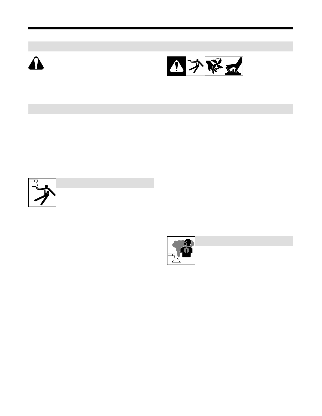
1-2. Arc Welding Hazards
Y The symbols shown below are used throughout this manual to
call attention to and identify possible hazards. When you see
the symbol, watch out, and follow the related instructions to
avoid the hazard. The safety information given below is only
a summary of the more complete safety information found in
the Safety Standards listed in Section 1-4. Read and follow all
Safety Standards.
Y Only qualified persons should install, operate, maintain, and
repair this unit.
Y During operation, keep everybody, especially children, away.
ELECTRIC SHOCK can kill.
Touching live electrical parts can cause fatal shocks
or severe burns. The electrode and work circuit is
electrically live whenever the output is on. The input
live when power is on. In semiautomatic or automatic wire welding, the
wire, wire reel, drive roll housing, and all metal parts touching the
welding wire are electrically live. Incorrectly installed or improperly
grounded equipment is a hazard.
D Do not touch live electrical parts.
D Wear dry, hole-free insulating gloves and body protection.
D Insulate yourself from work and ground using dry insulating mats
or covers big enough to prevent any physical contact with the work
or ground.
D Do not use AC output in damp areas, if movement is confined, or if
there is a danger of falling.
D Use AC output ONLY if required for the welding process.
D If AC output is required, use remote output control if present on
unit.
D Disconnect input power or stop engine before installing or
servicing this equipment. Lockout/tagout input power according to
OSHA 29 CFR 1910.147 (see Safety Standards).
D Properly install and ground this equipment according to its
Owner’s Manual and national, state, and local codes.
D Always verify the supply ground – check and be sure that input
power cord ground wire is properly connected to ground terminal in
disconnect box or that cord plug is connected to a properly
grounded receptacle outlet.
D When making input connections, attach proper grounding conduc-
tor first – double-check connections.
D Frequently inspect input power cord for damage or bare wiring –
replace cord immediately if damaged – bare wiring can kill.
D Turn off all equipment when not in use.
D Do not use worn, damaged, undersized, or poorly spliced cables.
D Do not drape cables over your body.
power circuit and machine internal circuits are also
This group of symbols means Warning! Watch Out! possible
ELECTRIC SHOCK, MOVING PARTS, and HOT PARTS hazards.
Consult symbols and related instructions below for necessary actions
to avoid the hazards.
D If earth grounding of the workpiece is required, ground it directly
with a separate cable.
D Do not touch electrode if you are in contact with the work, ground,
or another electrode from a different machine.
D Use only well-maintained equipment. Repair or replace damaged
parts at once. Maintain unit according to manual.
D Wear a safety harness if working above floor level.
D Keep all panels and covers securely in place.
D Clamp work cable with good metal-to-metal contact to workpiece
or worktable as near the weld as practical.
D Insulate work clamp when not connected to workpiece to prevent
contact with any metal object.
D Do not connect more than one electrode or work cable to any
single weld output terminal.
SIGNIFICANT DC VOLTAGE exists after removal of
input power on inverters.
D Turn Off inverter, disconnect input power, and discharge input
capacitors according to instructions in Maintenance Section
before touching any parts.
FUMES AND GASES can be hazardous.
Welding produces fumes and gases. Breathing
these fumes and gases can be hazardous to your
health.
D Keep your head out of the fumes. Do not breathe the fumes.
D If inside, ventilate the area and/or use exhaust at the arc to remove
welding fumes and gases.
D If ventilation is poor, use an approved air-supplied respirator.
D Read the Material Safety Data Sheets (MSDSs) and the
manufacturer’s instructions for metals, consumables, coatings,
cleaners, and degreasers.
D Work in a confined space only if it is well ventilated, or while
wearing an air-supplied respirator. Always have a trained watchperson nearby. Welding fumes and gases can displace air and
lower th e oxygen level causing injury or death. Be sure the breathing air is safe.
D Do not weld in locations near degreasing, cleaning, or spraying op-
erations. The heat and rays of the arc can react with vapors to form
highly toxic and irritating gases.
D Do not weld on coated metals, such as galvanized, lead, or
cadmium plated steel, unless the coating is removed from the weld
area, the area is well ventilated, and if necessary, while wearing an
air-supplied respirator. The coatings and any metals containing
these elements can give off toxic fumes if welded.
OM-355 Page 1
Page 6
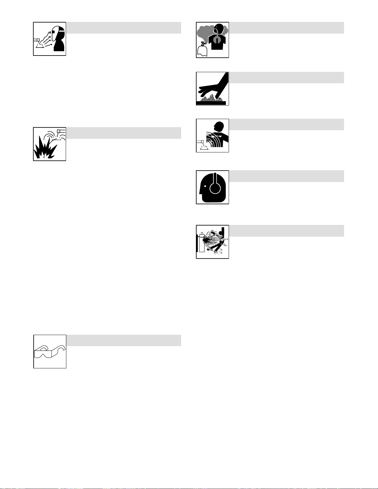
ARC RAYS can burn eyes and skin.
BUILDUP OF GAS can injure or kill.
Arc rays from the welding process produce intense
visible and invisible (ultraviolet and infrared) rays
that can burn eyes and skin. Sparks fly off from the
weld.
D Wear a welding helmet fitted with a proper shade of filter to protect
your face and eyes when welding or watching (see ANSI Z49.1
and Z87.1 listed in Safety Standards).
D Wear approved safety glasses with side shields under your
helmet.
D Use protective screens or barriers to protect others from flash and
glare; warn others not to watch the arc.
D Wear protective clothing made from durable, flame-resistant mate-
rial (leather and wool) and foot protection.
WELDING can cause fire or explosion.
Welding on closed containers, such as tanks,
drums, or pipes, can cause them to blow up. Sparks
can fly off from the welding arc. The flying sparks, hot
burns. Accidental contact of electrode to metal objects can cause
sparks, explosion, overheating, or fire. Check and be sure the area is
safe before doing any welding.
D Protect yourself and others from flying sparks and hot metal.
D Do not weld where flying sparks can strike flammable material.
D Remove all flammables within 35 ft (10.7 m) of the welding arc. If
this is not possible, tightly cover them with approved covers.
D Be alert that welding sparks and hot materials from welding can
easily go through small cracks and openings to adjacent areas.
D Watch for fire, and keep a fire extinguisher nearby.
D Be aware that welding on a ceiling, floor, bulkhead, or partition can
cause fire on the hidden side.
D Do not weld on closed containers such as tanks, drums, or pipes,
unless they are properly prepared according to AWS F4.1 (see
Safety Standards).
D Connect work cable to the work as close to the welding area as
practical to prevent welding current from traveling long, possibly
unknown paths and causing electric shock and fire hazards.
D Do not use welder to thaw frozen pipes.
D Remove stick electrode from holder or cut off welding wire at
contact tip when not in use.
D Wear oil-free protective garments such as leather gloves, heavy
shirt, cuffless trousers, high shoes, and a cap.
D Remove any combustibles, such as a butane lighter or matches,
from your person before doing any welding.
workpiece, and hot equipment can cause fires and
FLYING METAL can injure eyes.
D Welding, chipping, wire brushing, and grinding
cause sparks and flying metal. As welds cool,
they can throw off slag.
D Wear approved safety glasses with side
shields even under your welding helmet.
D Shut off shielding gas supply when not in use.
D Always ventilate confined spaces or use
approved air-supplied respirator.
HOT PARTS can cause severe burns.
D Do not touch hot parts bare handed.
D Allow cooling period before working on gun or
torch.
MAGNETIC FIELDS can affect pacemakers.
D Pacemaker wearers keep away.
D Wearers should consult their doctor before
going near arc welding, gouging, or spot
welding operations.
NOISE can damage hearing.
Noise from some processes or equipment can
damage hearing.
D Wear approved ear protection if noise level is
high.
CYLINDERS can explode if damaged.
Shielding gas cylinders contain gas under high
pressure. If damaged, a cylinder can explode. Since
gas cylinders are normally part of the welding
process, be sure to treat them carefully.
D Protect compressed gas cylinders from excessive heat, mechani-
cal shocks, slag, open flames, sparks, and arcs.
D Install cylinders in an upright position by securing to a stationary
support or cylinder rack to prevent falling or tipping.
D Keep cylinders away from any welding or other electrical circuits.
D Never drape a welding torch over a gas cylinder.
D Never allow a welding electrode to touch any cylinder.
D Never weld on a pressurized cylinder – explosion will result.
D Use only correct shielding gas cylinders, regulators, hoses, and fit-
tings designed for the specific application; maintain them and
associated parts in good condition.
D Turn face away from valve outlet when opening cylinder valve.
D Keep protective cap in place over valve except when cylinder is in
use or connected for use.
D Read and follow instructions on compressed gas cylinders,
associated equipment, and CGA publication P-1 listed in Safety
Standards.
OM-355 Page 2
Page 7
1-3. Additional Symbols For Installation, Operation, And Maintenance
FIRE OR EXPLOSION hazard.
D Do not install or place unit on, over, or near
combustible surfaces.
D Do not install unit near flammables.
D Do not overload building wiring – be sure power supply system is
properly sized, rated, and protected to handle this unit.
FALLING UNIT can cause injury.
D Use lifting eye to lift unit only, NOT running
gear, gas cylinders, or any other accessories.
D Use equipment of adequate capacity to lift and
support unit.
D If using lift forks to move unit, be sure forks are
long enough to extend beyond opposite side of
unit.
OVERUSE can cause OVERHEATING
D Allow cooling period; follow rated duty cycle.
D Reduce current or reduce duty cycle before
starting to weld again.
D Do not block or filter airflow to unit.
STATIC (ESD) can damage PC boards.
MOVING PARTS can cause injury.
D Keep away from moving parts such as fans.
D Keep all doors, panels, covers, and guards
closed and securely in place.
H.F. RADIATION can cause interference.
D High-frequency (H.F.) can interfere with radio
navigation, safety services, computers, and
communications equipment.
D Have only qualified persons familiar with
electronic equipment perform this installation.
D The user is responsible for having a qualified electrician prompt-
ly correct any interference problem resulting from the installation.
D If notified by the FCC about interference, stop using the
equipment at once.
D Have the installation regularly checked and maintained.
D Keep high-frequency source doors and panels tightly shut, keep
spark gaps at correct setting, and use grounding and shielding to
minimize the possibility of interference.
D Put on grounded wrist strap BEFORE handling
boards or parts.
D Use proper static-proof bags and boxes to
store, move, or ship PC boards.
MOVING PARTS can cause injury.
D Keep away from moving parts.
D Keep away from pinch points such as drive
rolls.
WELDING WIRE can cause injury.
D Do not press gun trigger until instructed to do
so.
D Do not point gun toward any part of the body,
other people, or any metal when threading
welding wire.
1-4. Principal Safety Standards
Safety in Welding and Cutting, ANSI Standard Z49.1, from American
Welding Society, 550 N.W. LeJeune Rd, Miami FL 33126
Safety and Health Standards, OSHA 29 CFR 1910, from Superintendent of Documents, U.S. Government Printing Office, Washington, D.C.
20402.
Recommended Safe Practices for the Preparation for Welding and Cutting of Containers That Have Held Hazardous Substances, American
Welding Society Standard AWS F4.1, from American Welding Society,
550 N.W. LeJeune Rd, Miami, FL 33126
National Electrical Code, NFPA Standard 70, from National Fire Protection Association, Batterymarch Park, Quincy, MA 02269.
ARC WELDING can cause interference.
D Electromagnetic energy can interfere with
sensitive electronic equipment such as
computers and computer-driven equipment
such as robots.
D Be sure all equipment in the welding area is
electromagnetically compatible.
D To reduce possible interference, keep weld cables as short as
possible, close together, and down low, such as on the floor.
D Locate welding operation 100 meters from any sensitive elec-
tronic equipment.
D Be sure this welding machine is installed and grounded
according t o this manual.
D If interference still occurs, the user must take extra measures
such as moving the welding machine, using shielded cables,
using line filters, or shielding the work area.
Safe Handling of Compressed Gases in Cylinders, CGA Pamphlet P-1,
from Compressed Gas Association, 1235 Jefferson Davis Highway,
Suite 501, Arlington, VA 22202.
Code for Safety in Welding and Cutting, CSA Standard W117.2, from
Canadian Standards Association, Standards Sales, 178 Rexdale
Boulevard, Rexdale, Ontario, Canada M9W 1R3.
Safe Practices For Occupation And Educational Eye And Face
Protection, ANSI Standard Z87.1, from American National Standards
Institute, 1430 Broadway, New York, NY 10018.
Cutting And Welding Processes, NFPA Standard 51B, from National
Fire Protection Association, Batterymarch Park, Quincy, MA 02269.
OM-355 Page 3
Page 8

1-5. EMF Information
Considerations About Welding And The Effects Of Low Frequency
Electric And Ma g netic Fields
Welding current, as it flows through welding cables, will cause electromagnetic fields. There has been and still is some concern about such
fields. However, after examining more than 500 studies spanning 17
years of research, a special blue ribbon committee of the National
Research Council concluded that: “The body of evidence, in the
committee’s judgment, has not demonstrated that exposure to power-
frequency electric and magnetic fields is a human-health hazard.”
However, studies are still going forth and evidence continues to be
examined. Until the final conclusions of the research are reached, you
may wish to minimize your exposure to electromagnetic fields when
welding or cutting.
To reduce magnetic fields in the workplace, use the following
procedures:
1. Keep cables close together by twisting or taping them.
2. Arrange cables to one side and away from the operator.
3. Do not coil or drape cables around your body.
4. Keep welding power source and cables as far away from operator as practical.
5. Connect work clamp to workpiece as close to the weld as possible.
About Pacemakers:
Pacemaker wearers consult your doctor first. If cleared by your doctor,
then following the above procedures is recommended.
OM-355 Page 4
Page 9
SECTION 1 – CONSIGNES DE SECURITE – LIRE AVANT
UTILISATION
som _nd_fre 4/98
1-1. Signification des symboles
Signifie Mise en garde ! Soyez vigilant ! Cette procédure
présente des risques de danger ! Ceux-ci sont identifiés
par des symboles adjacents aux directives.
Y Identifie un message de sécurité particulier.
. Signifie NOTA ; n’est pas relatif à la sécurité.
1-2. Dangers relatifs au soudage à l’arc
Y Les symboles présentés ci-après sont utilisés tout au long du
présent manuel pour attirer votre attention et identifier les risques
de danger. Lorsque vous voyez un symbole, soyez vigilant et
suivez les directives mentionnées afin d’éviter tout danger. Les
consignes de sécurité présentées ci-après ne font que résumer
l’information contenue dans les normes de sécurité énumérées
à la section 1-4. Veuillez lire et respecter toutes ces normes de
sécurité.
Y L’installation, l’utilisation, l’entretien et les réparations ne doi-
vent être confiés qu’à des personnes qualifiées.
Y Au cours de l’utilisation, tenir toute personne à l’écart et plus par-
ticulièrement les enfants.
UN CHOC ÉLECTRIQUE peut tuer.
Un simple contact avec des pièces électriques peut
provoquer une électrocution ou des blessures graves.
L’électrode et le circuit de soudage sont sous tension
dès que l’appareil est sur ON. Le circuit d’entrée et les
tension à ce moment-là. En soudage semi-automatique ou automatique,
le fil, le dévidoir, le logement des galets d’entraînement et les pièces
métalliques en contact avec le fil de soudage sont sous tension. Des
matériels mal installés ou mal mis à la terre présentent un danger.
D Ne jamais toucher les pièces électriques sous tension.
D Porter des gants et des vêtements de protection secs ne comportant
pas de trous.
D S’isoler de la pièce et de la terre au moyen de tapis ou d’autres
moyens isolants suffisamment grands pour empêcher le contact physique éventuel avec la pièce ou la terre.
D Ne pas se servir de source électrique àcourant électrique dans les zones
humides, dans les endroits confinés ou là où on risque de tomber.
D Se servir d’une source électrique àcourant électrique UNIQUEMENT si le
procédé de soudage le demande.
D Si l’utilisation d’une source électrique àcourant électrique s’avère néces-
saire, se servir de la fonction de télécommande si l’appareil en est équipé.
D Couper l’alimentation ou arrêter le moteur avant de procéder à l’instal-
lation, à la réparation ou à l’entretien de l’appareil. Déverrouiller
l’alimentation selon la norme OSHA 29 CFR 1910.147 (voir normes de
sécurité).
D Installer et mettre à la terre correctement cet appareil conformément à
son manuel d’utilisation et aux codes nationaux, provinciaux et
municipaux.
D Toujours v érifier la terre du cordon d’alimentation – Vérifier et s’assu-
rer que le fil de terre du cordon d’alimentation est bien raccordé à la
borne de terre du sectionneur ou que la fiche du cordon est raccordée
à une prise correctement mise à la terre.
D En effectuant les raccordements d’entrée fixer d’abord le conducteur
de mise à la terre approprié et contre-vérifier les connexions.
D Vérifier fréquemment le cordon d’alimentation pour voir s’il n’est pas
endommagé ou dénudé – remplacer le cordon immédiatement s’il est
endommagé – un câble dénudé peut provoquer une électrocution.
D Mettre l’appareil hors tension quand on ne l’utilise pas.
D Ne pas utiliser des câbles usés, endommagés, de grosseur insuffi-
sante ou mal épissés.
D Ne pas enrouler les câbles autour du corps.
D Si la pièce soudée doit être mise à la terre, le faire directement avec un
câble distinct.
D Ne pas toucher l’électrode quand on est en contact avec la pièce, la
terre ou une électrode provenant d’une autre machine.
circuits internes de l’appareil sont également sous
Ce groupe de symboles signifie Mise en garde ! Soyez vigilant ! Il y a des
risques de danger reliés aux CHOCS ÉLECTRIQUES, aux PIÈCES EN
MOUVEMENT et aux PIÈCES CHAUDES. Reportez-vous aux symboles
et aux directives ci-dessous afin de connaître les mesures à prendre pour
éviter tout danger.
D N’utiliser qu’un matériel en bon état. Réparer ou remplacer sur-le-
champ les pièces endommagées. Entretenir l’appareil conformément
à ce manuel.
D Porter un harnais de sécurité quand on travaille en hauteur.
D Maintenir solidement en place tous les panneaux et capots.
D Fixer le câble de retour de façon à obtenir un bon contact métal-métal
avec la pièce à souder ou la table de travail, le plus près possible de l a
soudure.
D Isoler la pince de masse quand pas mis à la pièce pour éviter le contact
avec tout objet métallique.
Il y a DU COURANT CONTINU IMPORT ANT dans les
convertisseurs après la suppression de l’alimenta-
tion électrique.
D Arrêter les convertisseurs, débrancher le courant électrique, et dé-
charger les condensateurs d’alimentation selon les instructions
indiquées dans la partie entretien avant de toucher les pièces.
LES FUMÉES ET LES GAZ peuvent
être dangereux.
Le soudage génère des fumées et des gaz. Leur
inhalation peut être dangereux pour votre santé.
D Eloigner votre tête des fumées. Ne pas respirer
D A l’intérieur, ventiler la zone et/ou utiliser un échappement au niveau
de l’arc pour l’évacuation des fumées et des gaz de soudage.
D Si la ventilation est insuffisante, utiliser un respirateur à alimenta-
tion d’air homologué.
D Lire les spécifications de sécurité des matériaux (MSDSs) et les
instructions du fabricant concernant les métaux, les consommables, les revêtements, les nettoyants et les dégraisseurs.
D Travailler dans un espace fermé seulement s’il est bien ventilé ou en
portant un respirateur à alimentation d’air. Demander toujours à un
surveillant dûment formé de se tenir à proximité. Des fumées et des
gaz de soudage peuvent déplacer l’air et abaisser le niveau d’oxygène provoquant des blessures ou des accidents mortels. S’assurer que l’air de respiration ne présente aucun danger.
D Ne pas souder dans des endroits situés à proximité d’opérations de
dégraissage, de nettoyage ou de pulvérisation. La chaleur et les
rayons de l ’arc peuvent réagir en présence de vapeurs et former des
gaz hautement toxiques et irritants.
D Ne pas souder des métaux munis d’un revêtement, tels que l’acier
galvanisé, plaqué en plomb ou au cadmium à moins que le revêtement n’ait été enlevé dans la zone de soudure, que l’endroit soit bien
ventilé, et si nécessaire, en portant un respirateur à alimentation
d’air. Les revêtements et tous les métaux renfermant ces éléments
peuvent dégager des fumées toxiques en cas de soudage.
les fumées.
OM-355 Page 5
Page 10
LES RAYONS DE L’ARC peuvent pro-
voquer des brûlures dans les yeux et
sur la peau.
Le rayonnement de l’arc du procédé de soudage
génère des rayons visibles et invisibles intenses
des brûlures dans les yeux et sur la peau. Des étincelles sont projetées
pendant le soudage.
D Porter un casque de soudage muni d’un écran de filtre approprié pour
protéger votre visage et vos yeux pendant le soudage ou pour regarder (voir ANSI Z49.1 et Z87.1 énuméré dans les normes de sécurité).
D Porter des protections approuvés pour les oreilles si le niveau sondre est
trop élevé.
D Utiliser des écrans ou des barrières pour protéger des tiers de l’éclair
et de l’éblouissement; demander aux autres personnes de ne pas regarder l’arc.
D Porter des vêtements de protection constitué dans une matière dura-
ble, résistant au feu (cuir ou laine) et une protection des pieds.
(ultraviolets et infrarouges) susceptibles de provoquer
LES ACCUMULATIONS DE GAZ risquent de provoquer des blessures ou
même la mort.
D Fermer l’alimentation du gaz protecteur en cas de
non utilisation.
D Veiller toujours à bien aérer les espaces confinés ou se servir d’un respi-
rateur d’adduction d’air homologué.
DES PIÈCES CHAUDES peuvent provoquer des brûlures graves.
D Ne pas toucher des parties chaudes à mains nues
D Prévoir une période de refroidissement avant
d’utiliser le pistolet ou la torche.
LE SOUDAGE peut provoquer un
incendie ou une explosion.
Le soudage effectué sur des conteneurs fermés tels
que des réservoirs, tambours ou des conduites peut
provoquer leur éclatement. Des étincelles peuvent être
les, des pièces chaudes et des équipements chauds peut provoquer des
incendies et des brûlures. Le contact accidentel de l’électrode avec des
objets métalliques peut provoquer des étincelles, une explosion, un
surchauffement o u u n incendie. A vant de commencer le soudage, vérifier
et s’assurer que l’endroit ne présente pas de danger.
D Se protéger et d’autres personnes de la projection d’étincelles et de
métal chaud.
D Ne pas souder dans un endroit là où des étincelles peuvent tomber sur
des substances inflammables.
D Déplacer toutes les substances inflammables à une distance de 10,7
m de l’arc de soudage. En cas d’impossibilité les recouvrir soigneusement avec des protections homologués.
D Des étincelles et des matériaux chauds du soudage peuvent facile-
ment passer dans d’autres zones en traversant de petites fissures et
des ouvertures.
D Surveiller tout déclenchement d’incendie et tenir un extincteur à proxi-
mité.
D Le soudage effectué sur un plafond, plancher, paroi ou séparation
peut déclencher un incendie de l’autre côté.
D Ne pas effectuer le soudage sur des conteneurs fermés tels que des
réservoirs, tambours, ou conduites, à moins qu’ils n’aient été préparés correctement conformément à AWS F4.1 (voir les normes de
sécurité).
D Brancher le câble sur la pièce le plus près possible de la zone de sou-
dage pour éviter le transport du courant sur une longue distance par
des chemins inconnus éventuels en provoquant des risques d’élec-
trocution et d’incendie.
D Ne pas utiliser le poste de soudage pour dégeler des conduites ge-
lées.
D En cas de non utilisation, enlever la baguette d’électrode du porte-
électrode ou couper le fil à la pointe de contact.
D Porter des vêtements de protection dépourvus d’huile tels que des
gants en cuir, une chemise en matériau lourd, des pantalons sans re-
vers, des chaussures hautes et un couvre chef.
D Avant de souder, retirer toute substance combustible de vos poches
telles qu’un allumeur au butane ou des allumettes.
projetées de l’arc de soudure. La projection d’étincel-
DES PARTICULES VOLANTES
peuvent blesser les yeux.
D Le soudage, l’écaillement, le passage de la pièce
à la brosse en fil de fer, et le meulage génèrent
lantes. Pendant la période de refroidissement des soudures, elles ris-
quent de projeter du laitier.
D Porter des lunettes de sécurité avec écrans latéraux ou un écran facial.
des étincelles et des particules métalliques vo-
LES CHAMPS MAGNÉTIQUES peuvent
affecter les stimulateurs cardiaques.
D Porteurs d e stimulateur cardiaque, restez à distance.
D Les porteurs d’un stimulateur cardiaque doivent
d’abord consulter leur médecin avant de s’approcher
des opérations de soudage à l’arc, de gougeage ou
de soudage par points.
LE BRUIT peut affecter l’ouïe.
Le bruit des processus et des équipements peut affecter
l’ouïe.
D Porter des protections approuvés pour les oreilles si
le niveau sondre est trop élevé.
Si des BOUTEILLES sont endommagées, elles pourront exploser.
Des bouteilles de gaz protecteur contiennent du gaz
sous haute pression. Si une bouteille est endommagée, elle peut exploser. Du fait que les bouteilles de gaz
manipuler avec précaution.
D Protéger les bouteilles de gaz comprimé d’une chaleur excessive,
des chocs mécaniques, du laitier, des flammes ouvertes, des étin-
celles et des arcs.
D Placer les bouteilles debout en les fixant dans un support stationnai-
re ou dans un porte-bouteilles pour les empêcher de tomber ou de
se renverser.
D Tenir les bouteilles éloignées des circuits d e soudage ou autres cir-
cuits électriques.
D Ne jamais placer une torche de soudage sur une bouteille à gaz.
D Une électrode de soudage ne doit jamais entrer en contact avec une
bouteille.
D Ne jamais souder une bouteille pressurisée – risque d’explosion.
D Utiliser seulement des bouteilles de gaz protecteur, régulateurs,
tuyaux et raccords convenables pour cette application spécifique;
les maintenir ainsi que les éléments associés en bon état.
D Ne pas tenir la tête en face de la sortie en ouvrant la soupape de la
bouteille.
D Maintenir le chapeau de protection sur la soupape, sauf en cas d’uti-
lisation ou de branchement de la bouteille.
D Lire et suivre les instructions concernant les bouteilles de gaz com-
primé, les équipements associés et les publications P-1 CGA énumérées dans les normes de sécurité.
font normalement partie du procédé de soudage, les
OM-355 Page 6
Page 11
1-3. Dangers supplémentaires en relation avec l’installation, le fonctionnement
et la maintenance
Risque D’INCENDIE OU
D’EXPLOSION.
D Ne pas placer l’appareil sur, au-dessus ou à proxi-
mité de surfaces infllammables.
D Ne pas installer l’appareil à proximité de produits inflammables
D Ne pas surcharger l’installation électrique – s”assurer que l’alimen-
tation est correctement dimensionné et protégé avant de mettre
l’appareil en service.
LA CHUTE DE L’APPAREIL peut
blesser.
D Utiliser l’anneau de levage uniquement pour sou-
lever l’appareil, NON PAS les chariot, les bouteilles de gaz ou tout autre accessoire.
D Utiliser un engin d’une capacité appropriée pour
D En utilisant des fourches de levage pour déplacer l’unité, s’assurer
que les fourches sont suffisamment longues pour dépasser du côté
opposé de l’appareil.
soulever l’appareil.
L’EMPLOI EXCESSIF peut
SURCHAUFFER L’ÉQUIPEMENT.
D Prévoir une période de refroidissement, respec-
ter le cycle opératoire nominal.
D Réduire le courant ou le cycle opératoire avant de
D Ne pas obstruer les passages d’air du poste.
recommancer le soudage.
DES ORGANES MOBILES peuvent
provoquer des blessures.
D Rester à l’écart des organes mobiles comme le
ventilateur.
D Maintenir fermés et fixement en place les portes,
panneaux, recouvrements et dispositifs de
protection.
LE RAYONNEMENT HAUTE FRÉ-
QUENCE (H.F.) risque de provoquer
des interférences.
D Le rayonnement haute frequence peut provoquer
des interférences avec les équipements de radio–navigation e t d e communication, les services
D Demander seulement à des personnes qualifiées familiarisées
avec des équipements électroniques de faire fonctionner l’installa-
tion.
D L’utilisateur est tenu de faire corriger rapidement par un électricien
qualifié les interférences résultant de l’installation.
D Si le FCC signale des interférences, arrêter immédiatement l’appa-
reil.
D Effectuer régulièrement le contrôle et l’entretien de l’installation.
D Maintenir soigneusement fermés les portes et les panneaux des
sources de haute fréquence, maintenir les éclateurs à une distance
correcte et utiliser une terre et et un blindage pour réduire les interfé-
rences éventuelles.
de sécurité et les ordinateurs.
LE SOUDAGE À L’ARC risque de
provoquer des interférences.
LES CHARGES ÉLECTROSTATI-
QUES peuvent endommager les circuits imprimés.
D Établir la connexion avec la barrette de terre
avant de manipuler des cartes ou des pièces.
D Utiliser des pochettes et des boîtes antistatiques
pour stocker, déplacer ou expédier des cartes de
circuits imprimes.
DES ORGANES MOBILES peuvent
provoquer des blessures.
D Ne pas s’approcher des organes mobiles.
D Ne pas s’approcher des points de coincement
tels que des rouleaux de commande.
LES FILS DE SOUDAGE peuvent provoquer des blessures.
D Ne pas appuyer sur la gachette avant d’en avoir
reçu l’instruction.
D Ne pas diriger le pistolet vers soi, d’autres person-
nes ou toute pièce mécanique en engageant le fil
de soudage.
D L’énergie électromagnétique risque de provoquer
des interférences pour l’équipement électronique
sensible tel que les ordinateurs et l’équipement
D Veiller à ce que tout l’équipement de la zone de soudage soit com-
patible électromagnétiquement.
D Pour réduire la possibilité d’interférence, maintenir les câbles de
soudage aussi courts que possible, les grouper, et les poser aussi
bas que possible (ex. par terre).
D Veiller à souder à une distance de 100 mètres de tout équipement
électronique sensible.
D Veiller à ce que ce poste de soudage soit posé et mis à la terre
conformément à ce mode d’emploi.
D En cas d’interférences après avoir pris les mesures précédentes, il
incombe à l’utilisateur de prendre des mesures supplémentaires tel-
les que le déplacement du poste, l’utilisation de câbles blindés, l’utilisation de filtres de ligne ou la pose de protecteurs dans la zone de
travail.
commandé par ordinateur tel que les robots.
LES CHAMPS MAGNÉTIQUES peuvent
affecter les stimulateurs cardiaques.
D Porteurs de stimulateur cardiaque, restez à dis-
tance.
D Les porteurs d’un stimulateur cardiaque doivent
d’abord consulter leur médecin avant de s’appro-
cher des opérations de soudage à l’arc, de gou-
geage ou de soudage par points.
OM-355 Page 7
Page 12

1-4. Principales normes de sécurité
Safety in Welding and Cutting, norme ANSI Z49.1, de l’American Wel-
ding Society, 550 N.W. Lejeune Rd, Miami FL 33126
Safety and Health Sandards, OSHA 29 CFR 1910, du Superintendent
of Documents, U.S. Government Printing Office, Washington, D.C.
20402.
Recommended Safe Practice for the Preparation for Welding and Cutting of Containers That Have Held Hazardous Substances, norme A WS
F4.1, de l ’American Welding Society , 550 N.W. Lejeune Rd, Miami FL
33126
National Electrical Code, NFPA Standard 70, de la National Fire Protection Association, Batterymarch Park, Quincy, MA 02269.
Safe Handling of Compressed Gases in Cylinders, CGA Pamphlet P-1,
de la Compressed Gas Association, 1235 Jefferson Davis Highway,
Suite 501, Arlington, VA 22202.
Règles de s écurité en soudage, coupage et procédés connexes, norme
CSA W117.2, de l’Association canadienne de normalisation, vente de
normes, 178 Rexdale Boulevard, Rexdale (Ontario) Canada M9W 1R3.
Safe Pra ctices For Occupation And Educational Eye And Face Protection, norme ANSI Z87.1, de l’American National Standards Institute,
1430 Broadway, New York, NY 10018.
Cutting and Welding Processes, norme NFP A 51B, de la National Fire
Protection Association, Batterymarch Park, Quincy, MA 02269.
1-5. Information sur les champs électromagnétiques
Données sur le soudage électrique et sur les ef fets, pour l ’organisme,
des champs magnétiques basse fréquence
Le courant de soudage, pendant son passage dans les câbles de soudage, causera des champs électromagnétiques. Il y a eu et il y a encore
un certain souci à propos de tels champs. Cependant, après avoir examiné plus de 500 études qui ont été faites pendant une période de
recherche de 17 ans, un comité spécial ruban bleu du National Research Council a conclu: “L’accumulation de preuves, suivant le
jugement du comité, n’a pas démontré que l’exposition aux champs
magnétiques et champs électriques à haute fréquence représente un
risque à la santé humaine”. Toutefois, des études sont toujours en cours
et les preuves continuent à être examinées. En attendant que les conclusions finales de la recherche soient établies, il vous serait
souhaitable de réduire votre exposition aux champs électromagnéti-
ques pendant le soudage ou le coupage.
Afin de réduire les champs électromagnétiques dans l’environnement
de travail, respecter les consignes suivantes :
1 Garder les câbles ensembles en les torsadant ou en les
attachant avec du ruban adhésif.
2 Mettre tous les câbles du côté opposé de l’opérateur.
3 Ne pas courber pas et ne pas entourer pas les câbles autour de
votre corps.
4 Garder le poste de soudage et les câbles le plus loin possible de
vous.
5 Relier la pince de masse le plus près possible de la zone de
soudure.
Consignes relatives aux stimulateurs cardiaques :
Les personnes qui portent un stimulateur cardiaque doivent avant tout
consulter leur docteur. Si vous êtes déclaré apte par votre docteur , il est
alors recommandé de respecter les consignes ci–dessus.
OM-355 Page 8
Page 13
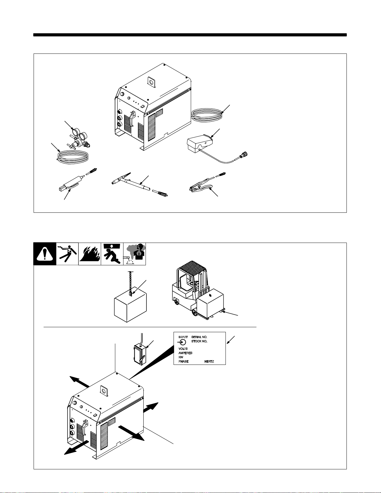
SECTION 2 – INSTALLATION
2-1. Included with Your Unit
5
4
1 12 ft (3.7 m) Work Cable
With Clamp And
Quick-Connect
2 150 Amp TIG Torch with
12-1/2 ft (3.8 m) Cable
3 Electrode Holder and
Quick-Connect
7
6
4 Gas Hose
5 Gas Regulator
6 RFCS-14 Foot Control with
20 ft (6 m) Cable
7 8 ft (2.4 m) Primary Cord
. Some assembly is required.
For options and accessories see
back of book or contact your distributor.
2
3
2-2. Selecting A Location
Movement
Location And Airflow
18 in
(460 mm)
1
OR
4
18 in (460
mm)
1
1 Lifting Eye
2 Lifting Forks
Use lifting eye or lifting forks to
move unit.
If using lifting forks, extend forks
beyond opposite side of unit.
3 Rating Label
Use rating label to determine input
power needs.
2
3
4 Line Disconnect Device
Locate unit near correct input pow-
er supply.
Position unit so air can circulate.
For information about sources of
high-frequency see Section 6.
For carts and caster kits see back
of book or contact your distributor.
Y Special installation may be
required where gasoline or
volatile liquids are present –
see NEC Article 511 or CEC
Section 2 0 .
18 in (460
mm)
18 in (460
mm)
ST-802 238
OM-355 Page 9
Page 14
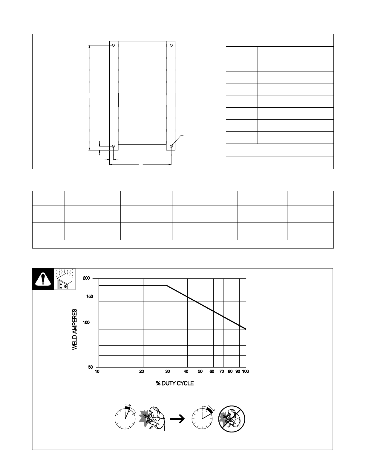
2-3. Dimensions And Weights
A
Dimensions
Height 21 in (533 mm)
Width 13-5/8 in (346 mm)
Length 22-1/8 in (562 mm)
A 21-5/16 in (541 mm)
B 13/16 in (21 mm)
C 12-7/16 in (316 mm)
D 1–1/16 in (27 mm)
4 HolesE
B
D
Front
C
ST-802 259
E 1/2 (13 mm)
Weight
210 lbs (95 kg)
2-4. Specifications
Rated Output at 40%
Mode
DC TIG 150 Amps at 16 Volts 230 V–38 A - (2)* 8.7 - (0.50)* 4.0 - (0.3)* 10–180 80
DC Stick 150 Amps at 26 Volts 230 V–42 A - (2)* 9.7 - (0.50)* 5.7 - (0.3)* 10–180 80
AC TIG 150 Amps at 16 Volts 230 V–67 A - (2)* 15.5 - (0.50)* 4.9 - (0.3)* 15–180 80
AC Stick 150 Amps at 26 Volts 230 V–53 A - (2)* 12.2 - (0.50)* 6.2 - (0.3)* 15–180 80
* () While idling.
Duty Cycle
Rated Input,
60 HZ, Single-Phase
KVA KW
Welding Amperage
Range
Max. Open-Circuit
Voltage
2-5. Duty Cycle Chart
Duty cycle is percentage of 10
minutes that unit can weld at rated
load without overheating.
Y Exceeding duty cycle can
damage unit and void
warranty.
OM-355 Page 10
40% Duty Cycle at 150 A AC/DC
4 Minutes Welding 6 Minutes Resting
ST-188 276-A
Page 15
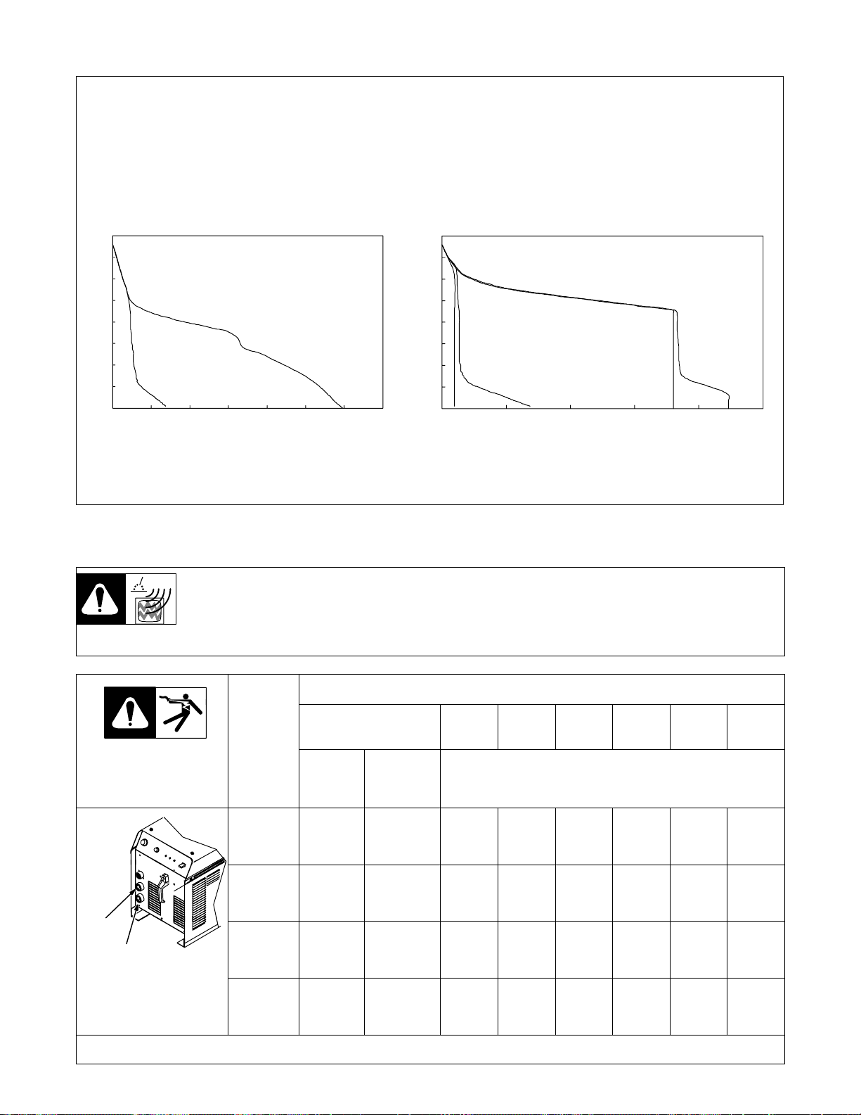
2-6. Volt-Ampere Curves
Volt-ampere curves show minimum
and maximum voltage and amperage output capabilities of welding
power source. Curves of other settings fall between curves shown.
AC MODE
80
70
60
50
40
VOLTS
30
20
10
0
0 50 100 150 200 250 300 350
Stick MIN Stick MAX
AMPERES
80
70
60
50
40
VOLTS
30
20
10
TIG–MIN STICK–MIN
0
0 50 100 150 200 250
2-7. Weld Output Terminals And Selecting Cable Sizes
Y ARC WELDING can cause Electromagnetic Interference.
To reduce possible interference, keep weld cables as short as possible, close together, and down low, such as on the floor.
Locate welding operation 100 meters from any sensitive electronic equipment. Be sure this welding machine is installed
and grounded according to this manual. If interference still occurs, the user must take extra measures such as moving
the welding machine, using shielded cables, using line filters, or shielding the work area.
DC MODE
AMPERES
TIG–MAX
ssb1.1 10/91 – ST-188 277 / ST-188 278
STICK–MAX
Total Cable (Copper) Length In Weld Circuit Not Exceeding
100 ft (30 m) Or Less
Weld Output
Terminals
Electrode
Work
Ref. ST-802 238
Weld cable size (AWG) is based on either a 4 volts or less drop or a current density of at least 300 circular mils per ampere. S-0007-D
Welding
Amperes
100 4 4 4 3 2 1 1/0 1/0
150 3 3 2 1 1/0 2/0 3/0 3/0
200 3 2 1 1/0 2/0 3/0 4/0 4/0
250 2 1 1/0 2/0 3/0 4/0 2-2/0 2-2/0
10 – 60%
Duty
Cycle
60 – 100%
Duty
Cycle
150 ft
(45 m)
200 ft
(60 m)
250 ft
(70 m)
10 – 100% Duty Cycle
300 ft
(90 m)
350 ft
(105 m)
OM-355 Page 11
400 ft
(120 m)
Page 16
2-8. Remote 14 Receptacle
NOTE
AJ
K
B
L
L
C
D
*The remaining sockets are not used.
I
NH
NH
M
G
F
E
E
ST-802 238
Remote control device has complete control of amperage at all times when
connected to Remote 14 receptacle.
Socket* Socket Information
A 24 volts DC.
B Contact closure to A completes 24 volts DC contactor control
circuit.
C Command reference; 0 to +10 volts DC output to remote control.
D Remote control circuit common.
A
E 0 to +10 volts DC input command signal from remote control.
K Chassis common.
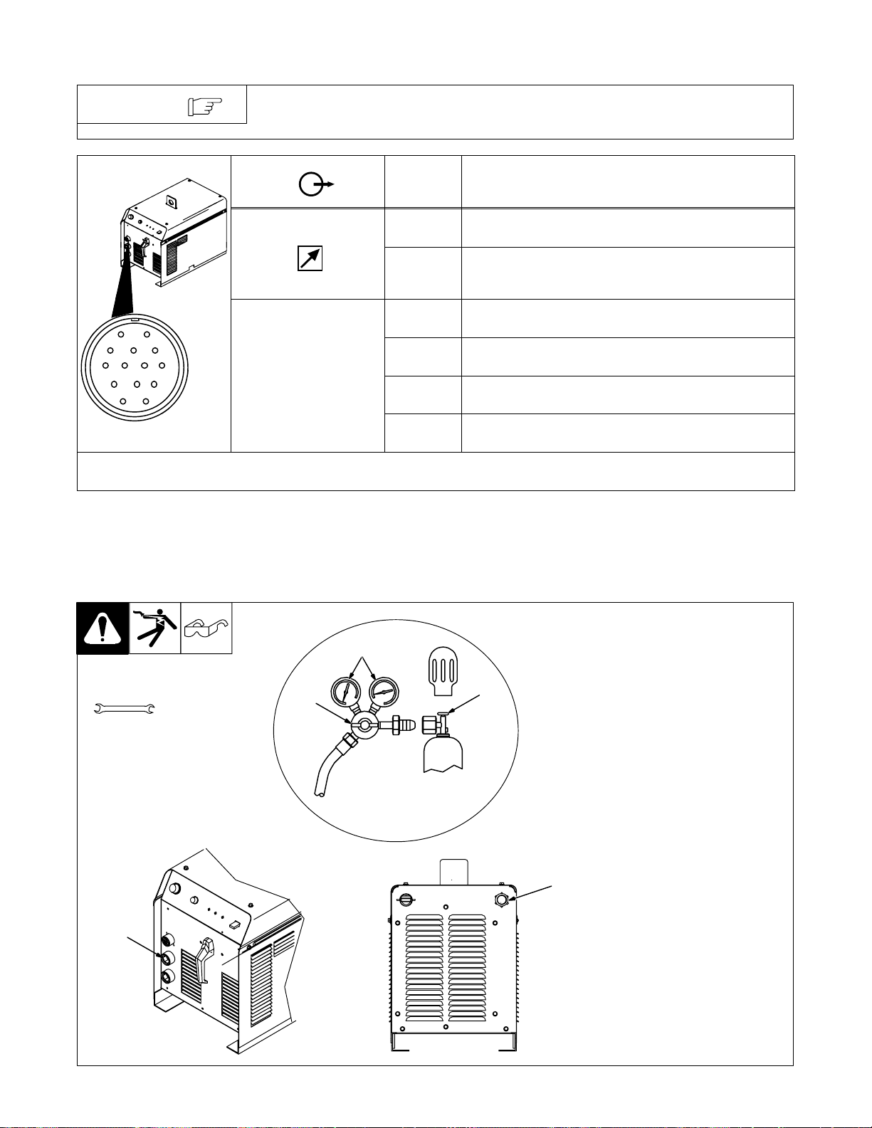
2-9. Shielding Gas Connections
Tools Needed:
5/8, 1-1/8 in
2
5
Y Turn Off power before con-
necting t o receptacle.
4
3
1
1 Gas Valve In Fitting
Fitting has 5/8-18 right-hand
threads.
Located o n rear of unit.
2 Gas Valve Out Fitting
Gas connection is integrated into
the Electrode weld output terminal
by means of a flow-through type
connector.
3 Cylinder Valve
Open valve slightly so gas flow
blows dirt from valve. Close valve.
4 Regulator/Flow Gauge
Connect regulator/flow gauge to
gas cylinder.
Connect gas hose to gas in fitting.
5 Flow Adjust
Typical flow rate is 20 cfh (cubic feet
per hour).
OM-355 Page 12
Ref. ST-802 238 / Ref. ST-802 258 / Ref. ST-157 858
Page 17
2-10. Electrical Service Guide
NOTE
Input Voltage 230
Input Amperes at Rated Output 67
Max Recommended Standard Fuse Or Circuit Breaker Rating In Amperes
Min Input Conductor Size In AWG/Kcmil
Max Recommended Input Conductor Length In Feet (Meters)
Min Grounding Conductor Size In AWG/Kcmil
Reference: 1996 National Electrical Code (NEC) S-0092-J
All values calculated at 40% duty cycle.
100
8
166 (51)
8
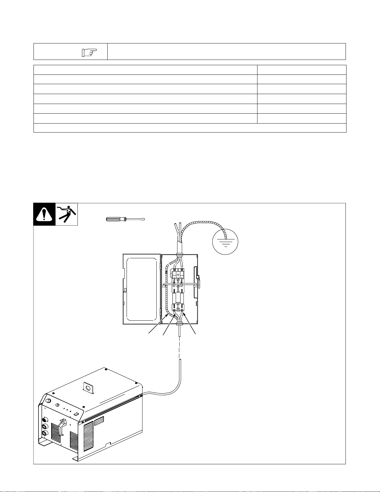
2-11. Connecting Input Power
Tools Needed:
GND/PE
Y Have only qualified persons
make this installation.
Y Special installation may be
required where gasoline or
volatile liquids are present –
see NEC Article 511 or CEC
Section 2 0 .
Units come equipped with input
power cord for installation into line
disconnect device. Select type and
size overcurrent protection using
Section 2-10.
GND/PE
Connect first.
L1 L2
ST-802 238
OM-355 Page 13
Page 18

3-1. Controls
SECTION 3 – OPERATION
23
46
5
7
1 Output Selector Switch
Y Do not use AC output in damp areas, if
movement is confined, or if there is
danger of falling. Use AC output ONLY
if required for the welding process, and
then use a remote control.
Y Do not change position of switch while
welding or while under load.
Use switch to select Direct Current Electrode
Negative (DCEN), AC, or Direct Current Electrode Positive (DCEP) output without changing
weld output cable connections.
2 Amperage Adjust Control
For Stick (SMAW), use control to adjust
amperage.
OM-355 Page 14
1
For remote amperage control used when TIG
(GTAW) welding, front panel Amperage control
setting is the maximum amperage available at
the remote control device.
See Section 3-3 for example of remote amperage control.
3 Weld Process Switch
Use switch to select weld process.
In Stick position (up), weld output goes On and
Off with Power switch.
In GT A W (TIG) position (down), remote control
device turns on and adjusts weld output of unit
as limited by Amperage control. For Direct Current Electrode Negative (DCEN), built-in arc
starter comes on when needed to start or stabi-
Ref. ST-188 714-A
lize welding arc. For AC welding, the arc starter
will turn on and stay on to start and stabilize the
welding arc. No adjustments needed for arc
starter.
4 Output (Contactor) Light
Lights when output (contactor) and unit power
are on.
5 Overtemp Light
Lights when unit overheats and shuts down
(see Section 4-3).
6 Pilot Light
7 Power Switch
Use switch to turn unit, fan, and pilot light On
and Off.
Page 19
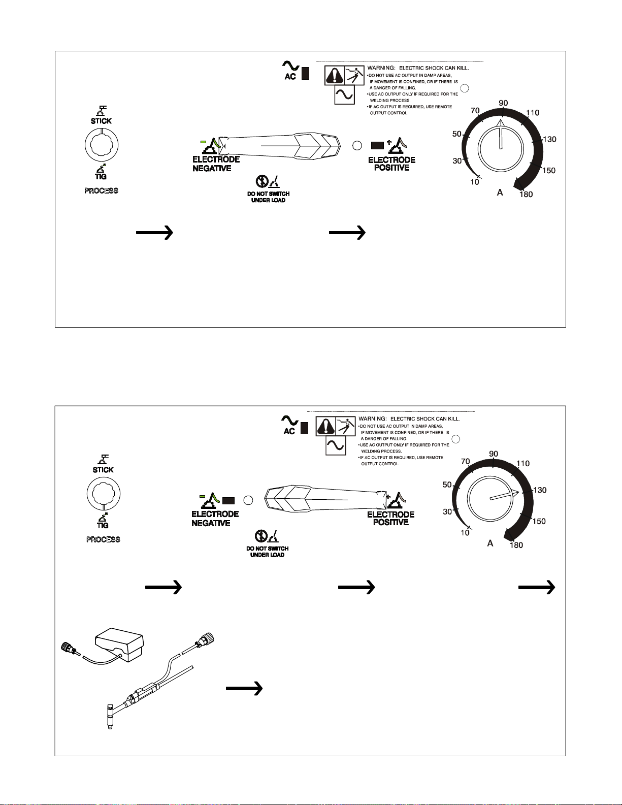
3-2. Example of Front Panel Amperage Control For Stick (SMAW) Welding
Select amperage.Select weld process. Select polarity.
Remote weld amperage = 10–180 amps DC
NOTE: Remote amperage control is active whenever a
remote control is connected. If the remote device does not
include a means of controlling amperage through pin E, the
Amperage Adjustment control on the front panel remains active.
In Example:
3-3. Example of Remote Amperage Control For TIG (GTAW) Welding
or
Connect remote control (see Section 3-4).
Select max amperageSelect weld process. Select polarity.
In Example:
For remote amperage control, front panel amperage control setting is the
maximum amperage available. Full range is 10–180 amps DC, but if front
panel amperage control is set at 130 amps, the range of remote
amperage control is 10 to 130 amps DC. NOTE: Remote amperage
control is active whenever a remote control is connected. If the
remote device does not include a means of controlling amperage through
pin E, the Amperage Adjustment control on the front panel remains active.
OM-355 Page 15
Page 20

3-4. Typical TIG Connections
7
Tools Needed:
5/8, 1-1/8 in
1
2
3
1 Remote Foot Control
6
5
4
A customer supplied remote fingertip control may also be used.
2 Torch
3 Work Clamp
Connect remote control, torch, and
work clamp to receptacles as
shown.
4 Cylinder
Chain or secure cylinder to running
gear, wall, or other stationary
support.
5 Cylinder Valve
Open valve slightly so gas flow
blows dirt from valve. Close valve.
6 Regulator/Flow Gauge
Install so face is vertical.
7 Flow Adjust
Typical flow rate is 20 cfh (cubic feet
per hour) (9.4 L/min).
NOTE: After activating remote con-
trol, 0.3 seconds of gas preflow will
begin.
Application:
Preflow is used to purge the immediate weld area of atmosphere.
Preflow also aids in consistent arc
starting.
NOTE: When remote control is
released, gas continues to flow for
18 seconds
Application:
Postflow is required to cool tungsten and weld, and to prevent contamination of tungsten and weld. Increase postflow time if tungsten or
weld are dark in appearance.
NOTE: Both preflow and postflow
are preset and are not adjustable.
NOTE: When AC welding, the balance control is preset at 60% electrode negative (EN), and 40% electrode positive (EP).
ST-802 238
3-5. Typical Stick Connections
1
2
OM-355 Page 16
1 Electrode Holder
2 Work Clamp
Connect electrode holder and work
clamp to receptacles as shown.
ST-802 238
Page 21
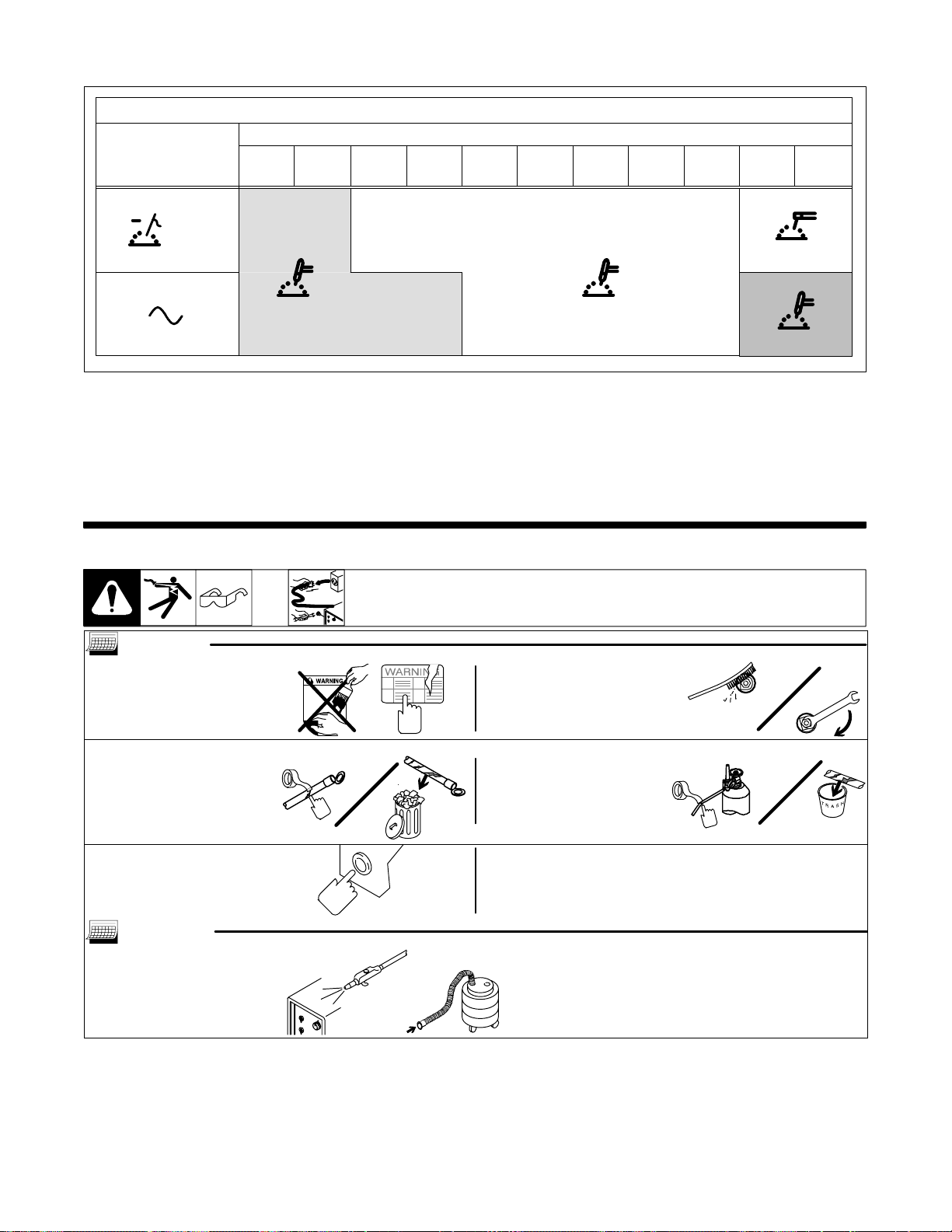
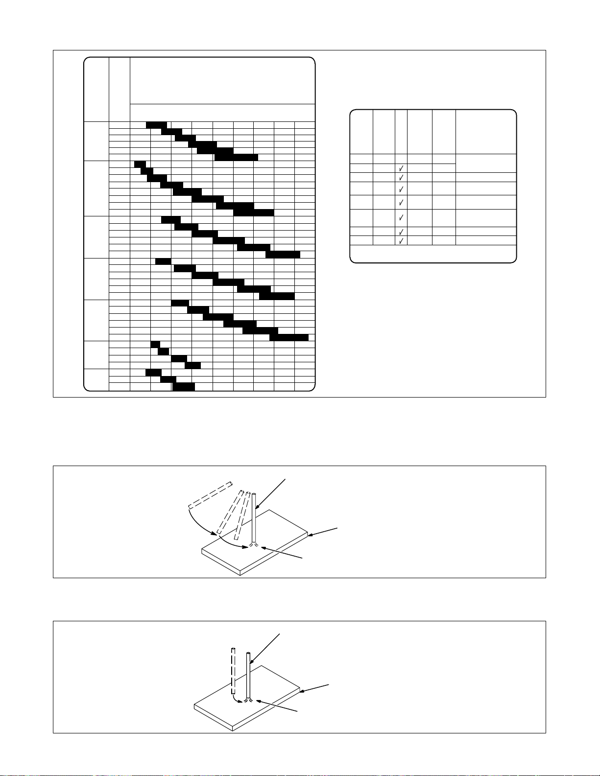
3-6. Process and Material Thickness Guide Label
Guideline For Welding Process And Output For Material
Material Thickness
Material And
Weld Output
Steel Or Stainless Steel
()
ELECTRODE
NEGATIVE
DCEN
Aluminum
AC
22 ga 20 ga 18 ga 16 ga 14 ga 12 ga 11 ga 10 ga 6 ga 2 ga –
0.033 in
0.8 mm
0.036 in
0.9 mm
GTAW
Difficult
0.048 in
1.2 mm
0.06 in
1.5 mm
0.07 in
1.8 mm
0.1 in
2.5 mm
Recommended
0.125 in
3.2 mm
GTAW
0.14 in
3.6 mm
0.186 in
4.8 mm
0.25 in
6.3 mm
Recommended
0.25+ in
6.3+ mm
SMAW
With DCEP
Output
GTAW
Not
SECTION 4 – MAINTENANCE AND TROUBLESHOOTING
S-167 338
4-1. Routine Maintenance
Y Disconnect power before maintaining.
. Maintain more often during severe conditions.
3 Months
Replace unreadable labels. Clean and tighten weld terminals.
Repair or replace cracked weld
cable.
Replace o-ring in Electrode/Gas
Output receptacle if cracked.
6 Months
Blow out or vacuum inside.
Or
Repair or replace cracked gas
hose.
OM-355 Page 17
Page 22
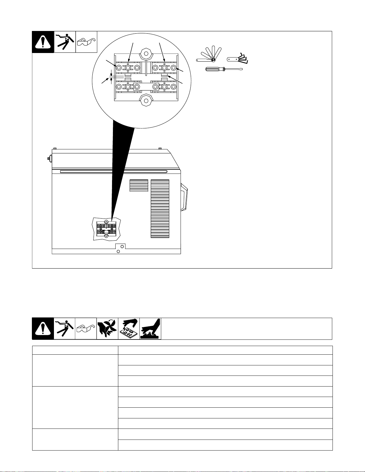
4-2. Adjusting Spark Gaps
4
3
2
4
3
1
Tools Needed:
Y Turn Off power before ad-
justing spark gaps.
Remove left side panel.
1 Tungsten End Of Point
Replace point if tungsten end dis-
appears; do not clean or dress
tungsten.
2 Spark Gap
Normal spark gap is 0.012 in (0.305
mm).
If adjustment is needed, proceed as
follows:
3 Adjustment Screws
Loosen screws. Place gauge of
proper thickness in spark gap.
4 Pressure Point
Apply slight pressure at point until
gauge is held firmly in gap. Tighten
screws to 12 in/lbs torque (overtightening will deform plastic base). Adjust other gap.
Reinstall left side panel.
4-3. Troubleshooting
Trouble Remedy
No weld output; fan does not run. Place line disconnect switch in On position (see Section 2-11).
Check and replace line fuse(s), if necessary, or reset circuit breaker (see Section 2-11).
Check for proper input power connections (see Section 2-11).
No weld output; fan on. Be sure Polarity switch is not set between positions.
Tighten remote control connection to Remote 14 receptacle.
Check remote control (see remote control Owner’s Manual).
Unit overheated. Allow unit to cool (see Section 2-5).
Fan not operating; weld output
available.
Check for and remove anything blocking fan movement.
Have Factory Authorized Service Agent check fan motor.
ST-802 745
OM-355 Page 18
Page 23
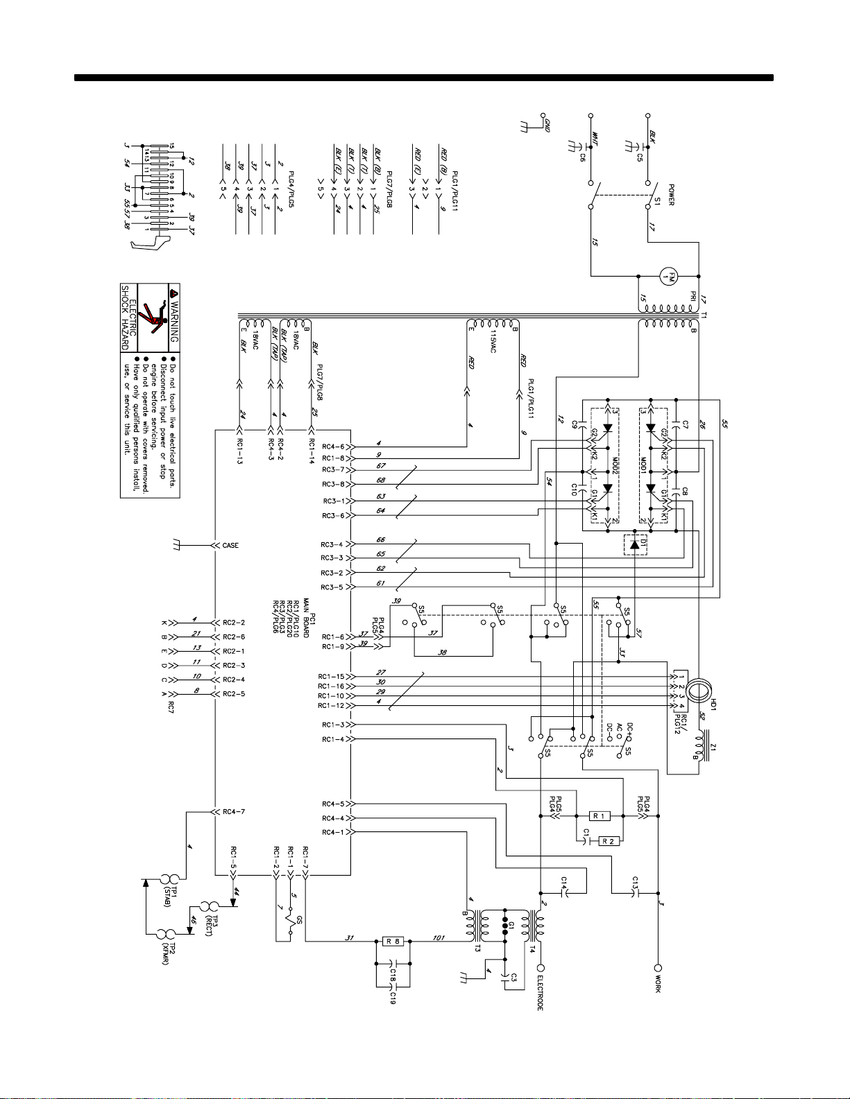
SECTION 5 – ELECTRICAL DIAGRAM
Figure 5-1. Circuit Diagram For Welding Power Source
SD-188 274-F
OM-355 Page 19
Page 24
SECTION 6 – HIGH FREQUENCY (HF)
6-1. Welding Processes Using HF
1
Work Work
1 HF V oltage
GTAW – helps arc jump air gap
between torch and workpiece and/
or stabilize the arc.
SAW – helps arc reach workpiece
2
1
through flux granules.
2 Flux
Gas Tungsten Arc
Welding (GT AW)
Submerged Arc
Welding (SAW)
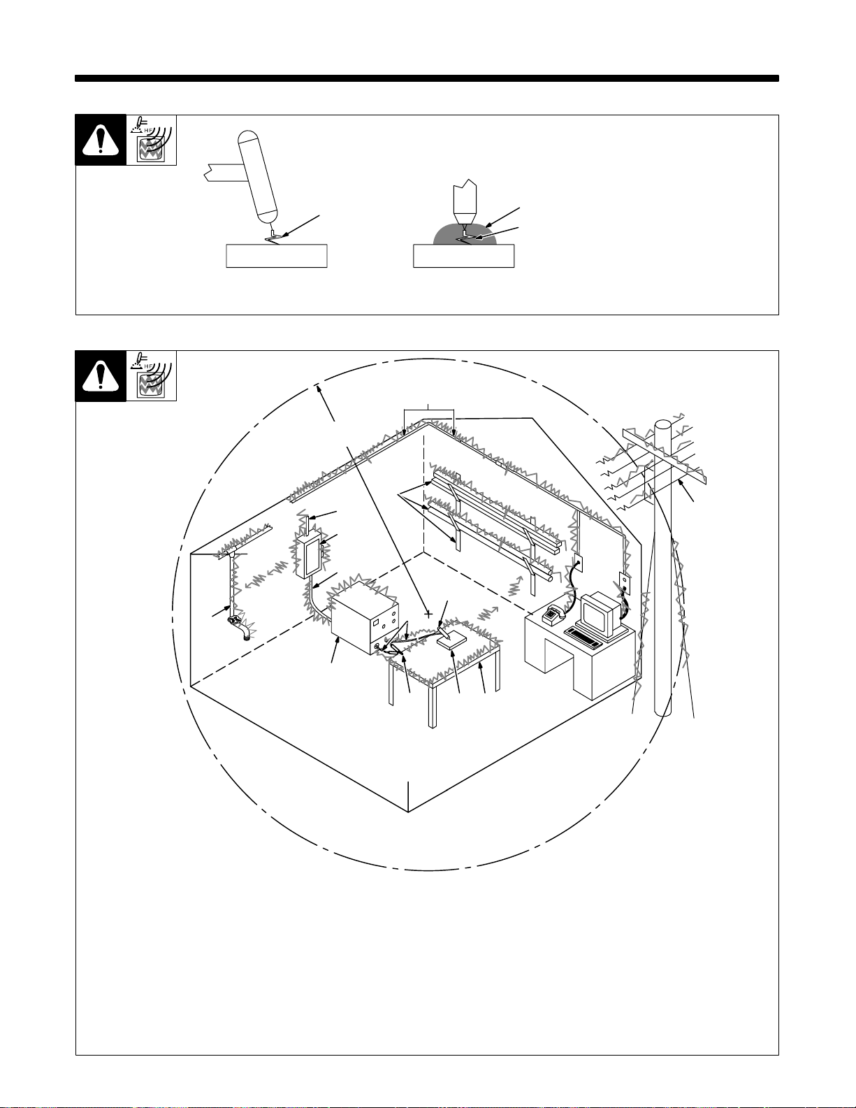
6-2. Sources Of HF Radiation From Incorrect Installation
Weld Zone
11, 12
50 ft
(15 m)
10
9
8
7
3
13
1
2
high_freq1 7/95 – S-0693
14
Sources Of Direct HF Radiation
1 HF source (welding power source with
built-in HF or separate HF unit)
2 Weld Cables
3 Torch
4 Work Clamp
OM-355 Page 20
4 5 6
5 Workpiece
6 Work Table
Sources Of Conduction Of HF
7 Input Power Cable
8 Line Disconnect Device
9 Input Supply Wiring
S-0694
Sources Of Reradiation Of HF
10 Ungrounded Metal Objects
11 Lighting
12 Wiring
13 Water Pipes And Fixtures
14 External Phone And Power Lines
Page 25
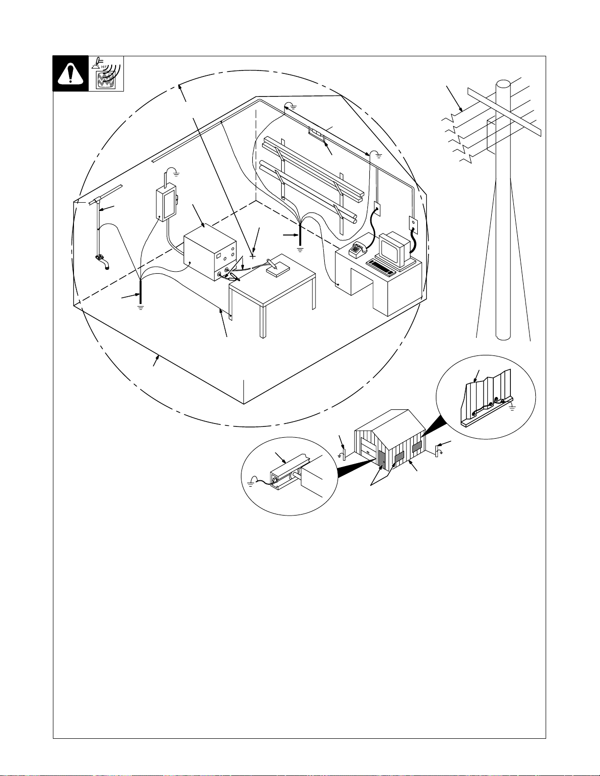
6-3. Correct Installation
Weld Zone
50 ft
(15 m)
Wire
1
2
7
3
Ground
Workpiece
If Required
By Codes
5
7
Ground All
Metal Objects
And All Wiring
In Welding Zone
Using #12 AWG
Nonmetal
Building
50 ft
(15 m)
4
6
8
1 HF Source (Welder With Built-In HF Or
Separate HF Unit)
Ground metal machine case, work output
terminal, line disconnect device, input
supply, and worktable.
2 Welding Zone And Centerpoint
A circle 50 ft (15 m) from centerpoint
between HF source and welding torch in all
directions.
3 Weld Output Cables
Keep cables short and close together.
4 Conduit Joint Bonding And Grounding
7
10
9
Electrically join (bond) all conduit sections
using copper straps or braided wire. Ground
conduit every 50 ft (15 m).
5 Water Pipes And Fixtures
Ground water pipes every 50 ft (15 m).
6 External Power Or Telephone Lines
Locate HF source at least 50 ft (15 m) away
from power and phone lines.
7 Grounding Rod
Consult the National Electrical Code for
specifications.
7
Metal Building
Ref. S-0695 / Ref. S-0695
8 Metal Building Panel Bonding Methods
Bolt or weld building panels together, install
copper straps or braided wire across seams,
and ground frame.
9 Windows And Doorways
Cover all windows and doorways with
grounded copper screen of not more than
1/4 in (6.4 mm) mesh.
10 Overhead Door Track
Ground the track.
OM-355 Page 21
Page 26

SECTION 7 – SELECTING AND PREPARING
TUNGSTEN ELECTRODE
gtaw2 7/97
NOTE
For additional information, see your distributor for a handbook on the Gas
Tungsten Arc Welding (GTAW) process. Wear clean gloves to prevent
contamination of tungsten electrode.
7-1. Selecting Tungsten Electrode
Electrode Diameter DC – Argon – Electrode Negative/Straight
2% Thorium Alloyed Tungsten (Red
Band)
.010” Up to 25 *
.020” 15-40 *
.040” 25-85 *
1/16” 50-160 10-20
3/32” 135-235 15-30
1/8” 250-400 25-40
5/32” 400-500 40-55
3/16” 500-750 55-80
1/4” 750-1000 80-125
Amperage Range - Gas Type♦ - Polarity
DC – Argon – Electrode Positive/Reverse
Polarity
Polarity
♦Typical argon shielding gas flow rates are 15 to 35 cfh (cubic feet per hour) – 7 to 16.5 lpm (liters per minute).
*Not Recommended.
The figures listed are intended as a guide and are a composite of recommendations from American Welding Society (AWS) and electrode
manufacturers.
7-2. Safety Information About Tungsten
Y Grinding the tungsten elec-
trode produces dust and flying sparks which can cause
1
2
injury and start fires. Use local exhaust (forced ventilation) at the grinder or wear an
approved respirator. Read
MSDS for safety information.
Consider using tungsten
containing ceria, lanthana,
or yttria instead of thoria.
Grinding dust from thoriated
electrodes contains low-level radioactive material.
Properly dispose of grinder
dust in an environmentally
safe way. Wear proper face,
hand, and body protection.
Keep flammables away.
1 Tungsten Electrode With
Balled End
2 Pointed Tungsten Electrode
OM-355 Page 22
Ref. S-0161
Page 27

7-3. Preparing Tungsten For DC Electrode Negative (DCEN) Welding
1 Tungsten Electrode
1
Electrode Diameter
4
Ideal Tungsten Preparation – Stable Arc
2
2-1/2 Times
1
2
3
2 Tapered End
Grind end of tungsten on fine grit,
hard abrasive wheel before welding. Do not use wheel for other jobs
or tungsten can become contaminated causing lower weld quality.
1 Stable Arc
2 Flat
Diameter of this flat determines
amperage capacity.
3 Grinding Wheel
4 Straight Ground
1
2
3
4
Wrong Tungsten Preparation – Wandering Arc
1 Arc Wander
2 Point
3 Grinding Wheel
4 Radial Ground
Ref. S-0161 / Ref. S-0162
OM-355 Page 23
Page 28

SECTION 8 – GUIDELINES FOR TIG WELDING (GTAW)
8-1. Positioning The Torch
Y Grinding the tungsten elec-
trode produces dust and flying sparks which can cause
injury and start fires. Use local exhaust (forced ventilation) at the grinder or wear an
approved respirator. Read
MSDS for safety information.
Consider using cerium or
lanthanum based tungsten
instead of thoriated. Thorium dust contains low-level
radioactive material. Properly dispose of grinder dust in
an environmentally safe way.
Wear proper face, hand, an d
body protection. Keep flammables away.
1 Workpiece
Make sure workpiece is clean
before welding.
2 Work Clamp
Place as close to the weld as
possible.
3 Torch
4 Filler Rod (If Applicable)
5 Gas Cup
6 Tungsten Electrode
Select and prepare tungsten
according to Sections 7-1, and 7-2
or 7-3.
Guidelines:
The inside diameter of the gas cup
should be at least three times the
tungsten diameter to provide adequate shielding gas coverage. (For
example, if tungsten is 1/16 in
diameter, gas cup should be a
minimum of 3/16 in diameter.
Tungsten extension is the distance
the tungsten extends out gas cup of
torch.
The tungsten extension should be
no greater than the inside diameter
of the gas cup.
Arc length is the distance from the
tungsten to the workpiece.
10–25°
2
1
10–15°
4
3/16 in
Bottom View Of Gas Cup
90°
5
3
4
5
6
6
1/16 in
OM-355 Page 24
Ref. ST-161 892
Page 29

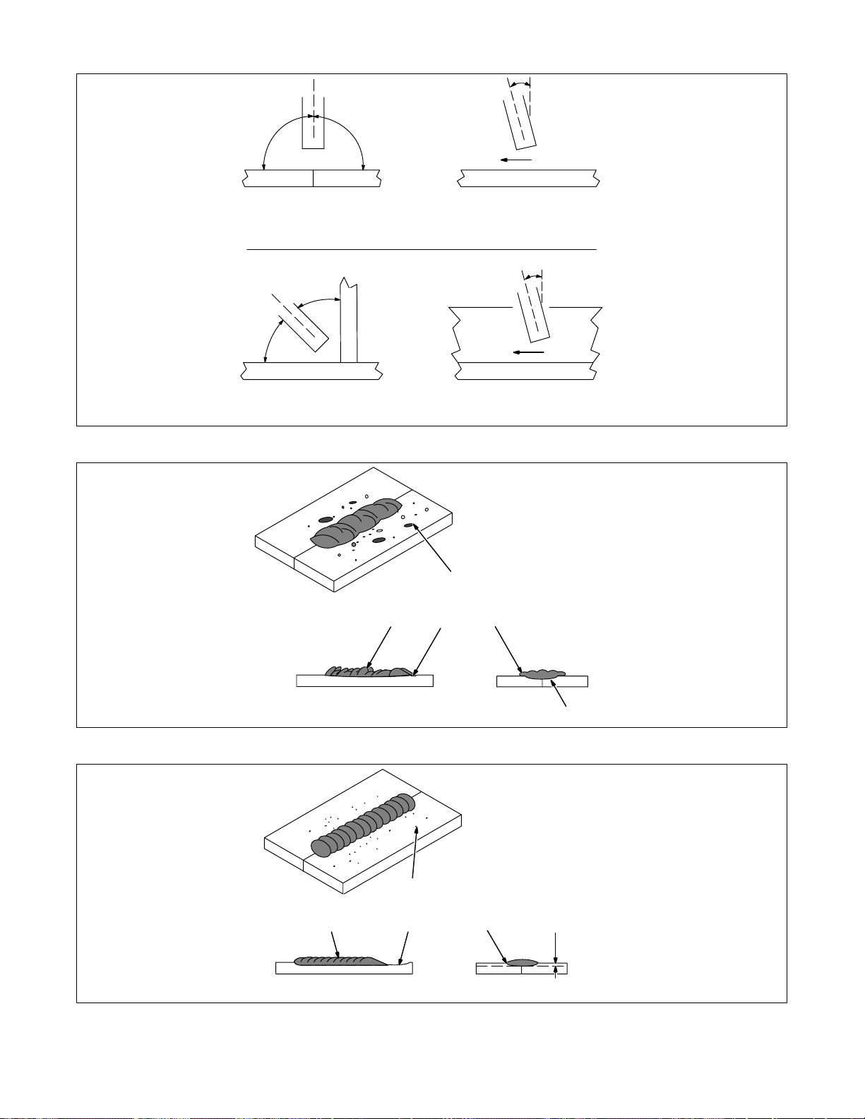
8-2. Torch Movement During Welding
Tungsten Without Filler Rod
Welding direction
Form pool Tilt torch Move torch to front
Tungsten With Filler Rod
Welding direction
Form pool Tilt torch Add filler metal
Remove rod
75°
of pool. Repeat process.
75°
15°
Move torch to front
of pool. Repeat process.
ST-162 002-B
OM-355 Page 25
Page 30

8-3. Positioning Torch Tungsten For Various Weld Joints
90°
Butt Weld And Stringer Bead
20°
20°
“T” Joint
70°
70°
Lap Joint
Corner Joint
10°
20°
40°
70°
20°
30°
90°
70°
OM-355 Page 26
20°
ST-162 003 / S-0792
Page 31

Notes
OM-355 Page 27
Page 32
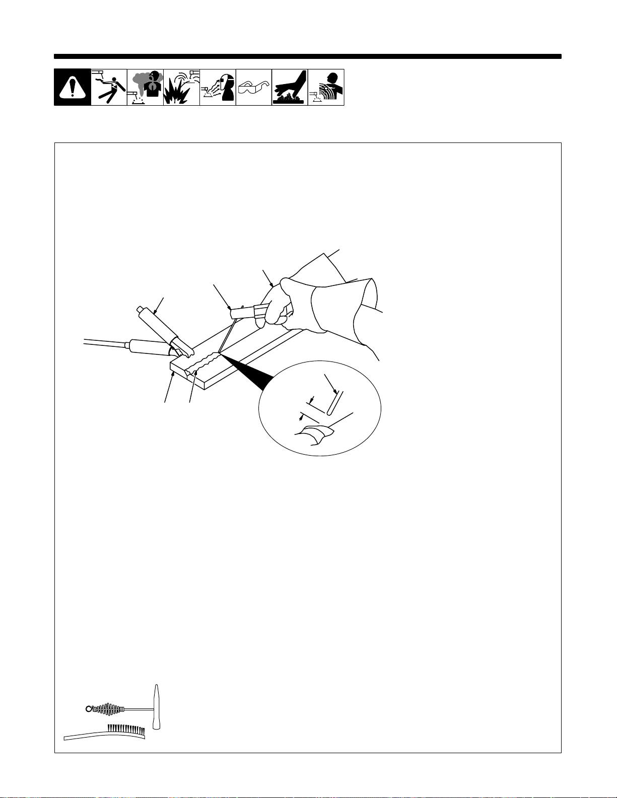
SECTION 9 – STICK WELDING (SMAW) GUIDELINES
9-1. Stick Welding Procedure
Y Weld current starts when
electrode touches workpiece.
Y Weld current can damage
electronic parts in vehicles.
Disconnect both battery
cables before welding on a
vehicle. P lace work clamp as
close t o the weld as possible.
1 Workpiece
Make sure workpiece is clean be-
5
4
2
3
6
1
7
fore welding.
2 Work Clamp
3 Electrode
A small diameter electrode requires
less current than a large one. Follow electrode manufacturer’s
instructions when setting weld amperage (see Section 9-2).
4 Insulated Electrode Holder
5 Electrode Holder Position
6 Arc Length
Arc length is the distance from the
electrode t o the workpiece. A short
arc with correct amperage will give
a sharp, crackling sound.
7 Slag
Use a chipping hammer and wire
brush to remove slag. Remove slag
and check weld bead before making another weld pass.
Tools Needed:
OM-355 Page 28
stick 12/96 – ST-151 593
Page 33
9-2. Electrode and Amperage Selection Chart
RANGE
AMPERAGE
ELECTRODE
6010
&
6011
6013
7014
7018
7024
Ni-Cl
308L
DIAMETER
3/32
1/8
5/32
3/16
7/32
1/4
1/16
5/64
3/32
1/8
5/32
3/16
7/32
1/4
3/32
1/8
5/32
3/16
7/32
1/4
3/32
1/8
5/32
3/16
7/32
1/4
3/32
1/8
5/32
3/16
7/32
1/4
3/32
1/8
5/32
3/16
3/32
1/8
5/32
50
100
150
200
250
300
350
400
450
AC
DC*
ELECTRODE
EP
6010
EP
6011
EP,EN
6013
EP,EN
7014
EP
7018
EP,EN
7024
EP
NI-CL
EP
308L
*EP = ELECTRODE POSITIVE (REVERSE POLARITY)
EN = ELECTRODE NEGATIVE (STRAIGHT POLARITY)
POSITION
ALL
ALL
ALL
ALL
ALL
FLAT
HORIZ
FILLET
ALL
ALL
PENETRATION
DEEP
DEEP
LOW
MED
LOW
LOW
LOW
LOW
USAGE
MIN. PREP, ROUGH
HIGH SPATTER
GENERAL
SMOOTH, EASY,
FAST
LOW HYDROGEN,
STRONG
SMOOTH, EASY,
FASTER
CAST IRON
STAINLESS
Ref. S-087 985-A
9-3. Striking an Arc – Scratch Start Technique
1
3
9-4. Striking an Arc – Tapping Technique
1
3
1 Electrode
2 Workpiece
3 Arc
Drag electrode across workpiece
2
like striking a match; lift electrode
slightly after touching work. If arc
goes out electrode was lifted to
high. If electrode sticks to workpiece, use a quick twist to free it.
S-0049
1 Electrode
2 Workpiece
3 Arc
Bring electrode straight down to
workpiece; then lift slightly to start
2
arc. If arc goes out, electrode was
lifted too high. If electrode sticks to
workpiece, use a quick twist to free it.
S-0050
OM-355 Page 29
Page 34
9-5. Positioning Electrode Holder
90° 90°
End View of Work Angle Side View of Electrode Angle
10°-30°
GROOVE WELDS
45°
45°
End View of Work Angle Side View of Electrode Angle
9-6. Poor Weld Bead Characteristics
FILLET WELDS
2
3
10°-30°
S-0060
1 Large Spatter Deposits
2 Rough, Uneven Bead
3 Slight Crater During Welding
4 Bad Overlap
5 Poor Penetration
1
4
9-7. Good Weld Bead Characteristics
OM-355 Page 30
5
1 Fine Spatter
2 Uniform Bead
3 Moderate Crater During
Welding
Weld a new bead or layer for each
1/8 in. (3.2 mm) thickness in metals
being w elded.
1
5234
4 No Overlap
5 Good Penetration into Base
Metal
S-0053-A
S-0052-B
Page 35
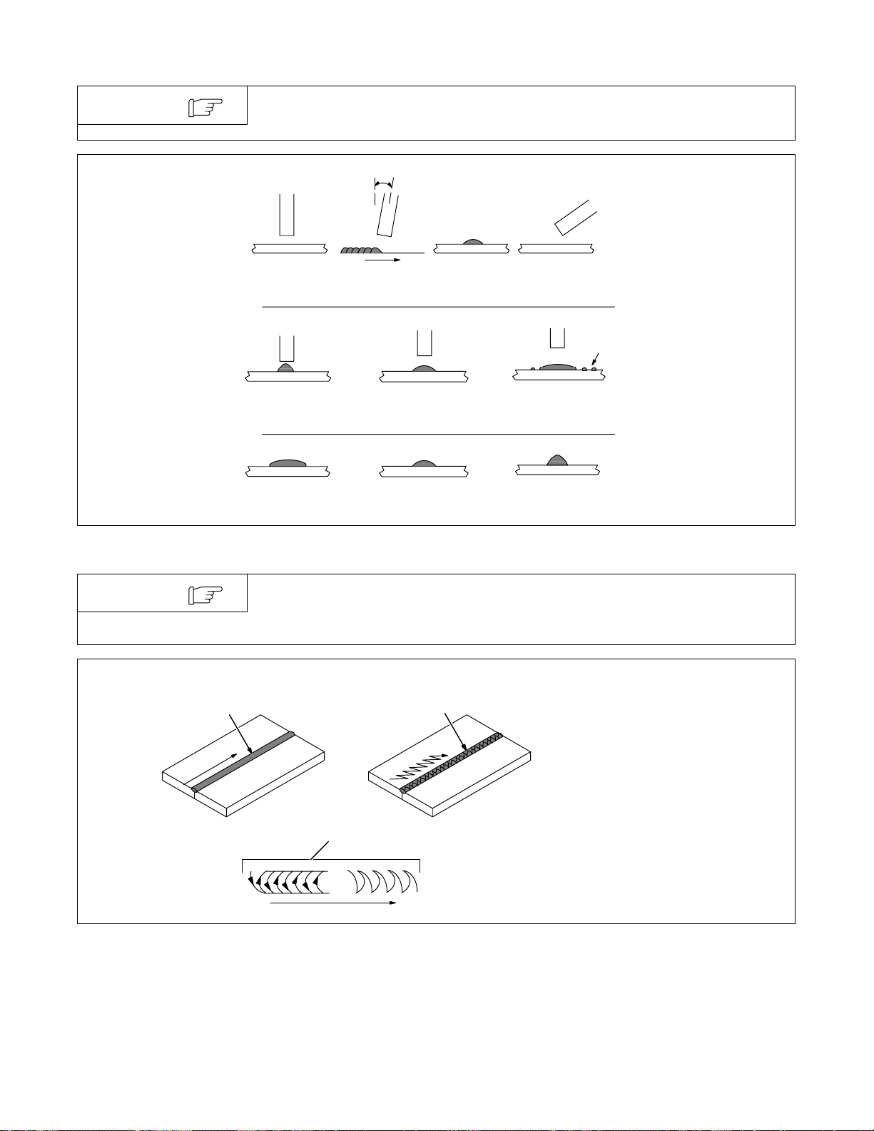
9-8. Conditions That Affect Weld Bead Shape
NOTE
Weld bead shape is affected by electrode angle, arc length, travel speed, and
thickness of base metal.
Angle Too Small
Too Short
Slow
Correct Angle
10° - 30°
Drag
ELECTRODE ANGLE
Normal Too Long
ARC LENGTH
Normal Fast
TRAVEL SPEED
Angle Too Large
Spatter
S-0061
9-9. Electrode Movement During Welding
NOTE
1
Normally , a single stringer bead is satisfactory for most narrow groove weld joints;
however, for wide groove weld joints or bridging across gaps, a weave bead or
multiple stringer beads work better.
3
1 Stringer Bead – Steady
Movement Along Seam
2
2 Weave Bead – Side to Side
Movement Along Seam
3 Weave Patterns
Use weave patterns to cover a wide
area in one pass of the electrode.
Do not let weave width exceed
2-1/2 times diameter of electrode.
S-0054-A
OM-355 Page 31
Page 36
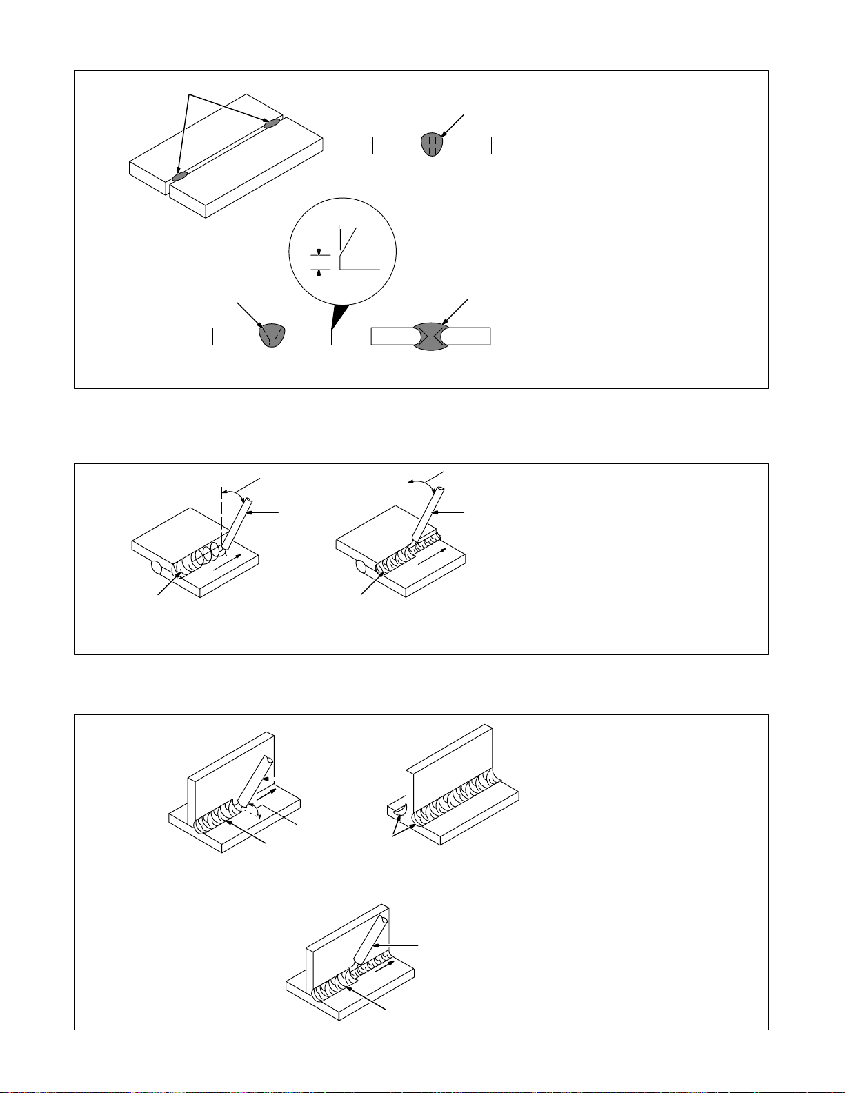
9-10. Butt Joints
1
9-11. Lap Joint
2
Single-Layer Fillet Weld
1 Tack Welds
2
30°
1/16 in
(1.6 mm)
3
30°
Or Less
11
3
Multi-Layer Fillet Weld
4
30°
Or Less
Prevent edges of joint from drawing
together ahead of electrode by tack
welding the materials in position before final weld.
2 Square Groove Weld
Good for materials up to 3/16 in (5
mm) thick.
3 Single V-Groove W eld
Good for materials 3/16 – 3/4 in
(5-19 mm) thick. Cut bevel with oxyacetylene or plasma cutting equipment. Remove scale from material
after cutting. A grinder can also be
used to prepare bevels.
Create 3 0 degree angle of bevel on
materials in V -groove welding.
4 Double V-Groove W eld
Good for materials thicker than 3/16
in (5 mm).
S-0662
1 Electrode
2 Single-Layer Fillet Weld
Move electrode in circular motion.
3 Multi-Layer Fillet Weld
Weld a second layer when a heavi-
er fillet is needed. Remove slag before making another weld pass.
Weld both sides of joint for maximum strength.
S-0063 / S-0064
9-12. Tee Joint
OM-355 Page 32
2
1
45°
Or Less
1 Electrode
2 Fillet Weld
Keep arc short and move at definite
rate of speed. Hold electrode as
shown to provide fusion into the
corner. Square edge of the weld
surface.
For maximum strength weld both
2
1
3
sides of upright section.
3 Multi-Layer Deposits
Weld a second layer when a heavi-
er fillet is needed. Use any of the
weaving patterns shown in Section
9-9. Remove slag before making
another weld pass.
S-0060 / S-0058-A / S-0061
Page 37
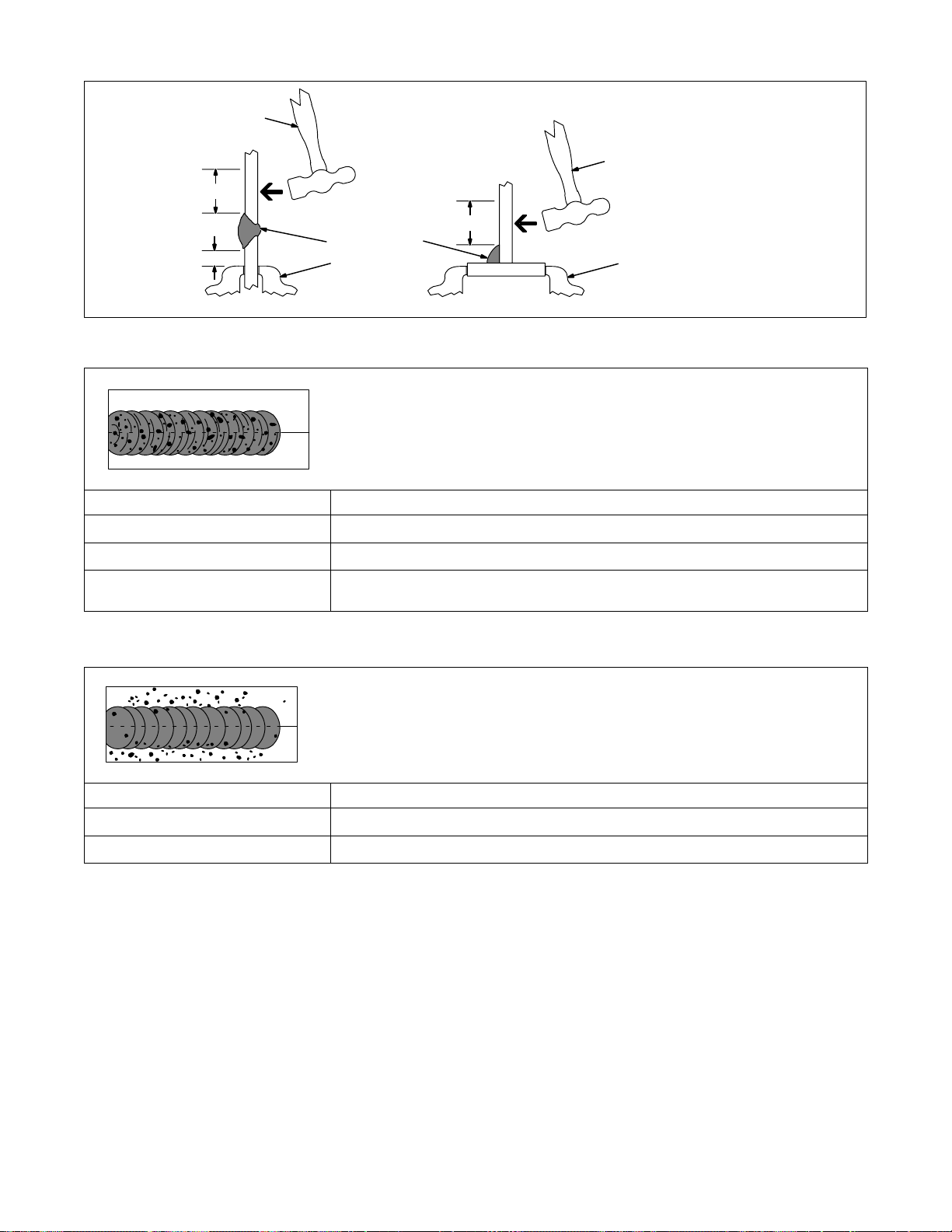
9-13. Weld Test
3
2 To 3 in
(51-76 mm)
2 To 3 in
(51-76 mm)
1/4 in
(6.4 mm)
2
1
2
9-14. Troubleshooting – Porosity
Porosity – small cavities or holes resulting from gas
pockets in weld metal.
Possible Causes Corrective Actions
Arc length too long. Reduce arc length.
1 Vise
2 Weld Joint
3 Hammer
3
1
Strike weld joint in direction shown.
A good weld bends over but does
not break.
S-0057-B
Damp electrode. Use dry electrode.
Workpiece dirty. Remove all grease, oil, moisture, rust, paint, coatings, slag, and dirt from work surface before
welding.
9-15. Troubleshooting – Excessive Spatter
Excessive Spatter – scattering of molten metal particles
that cool to solid form near weld bead.
Possible Causes Corrective Actions
Amperage too high for electrode. Decrease amperage or select larger electrode.
Arc length too long or voltage too high. Reduce arc length or voltage.
OM-355 Page 33
Page 38
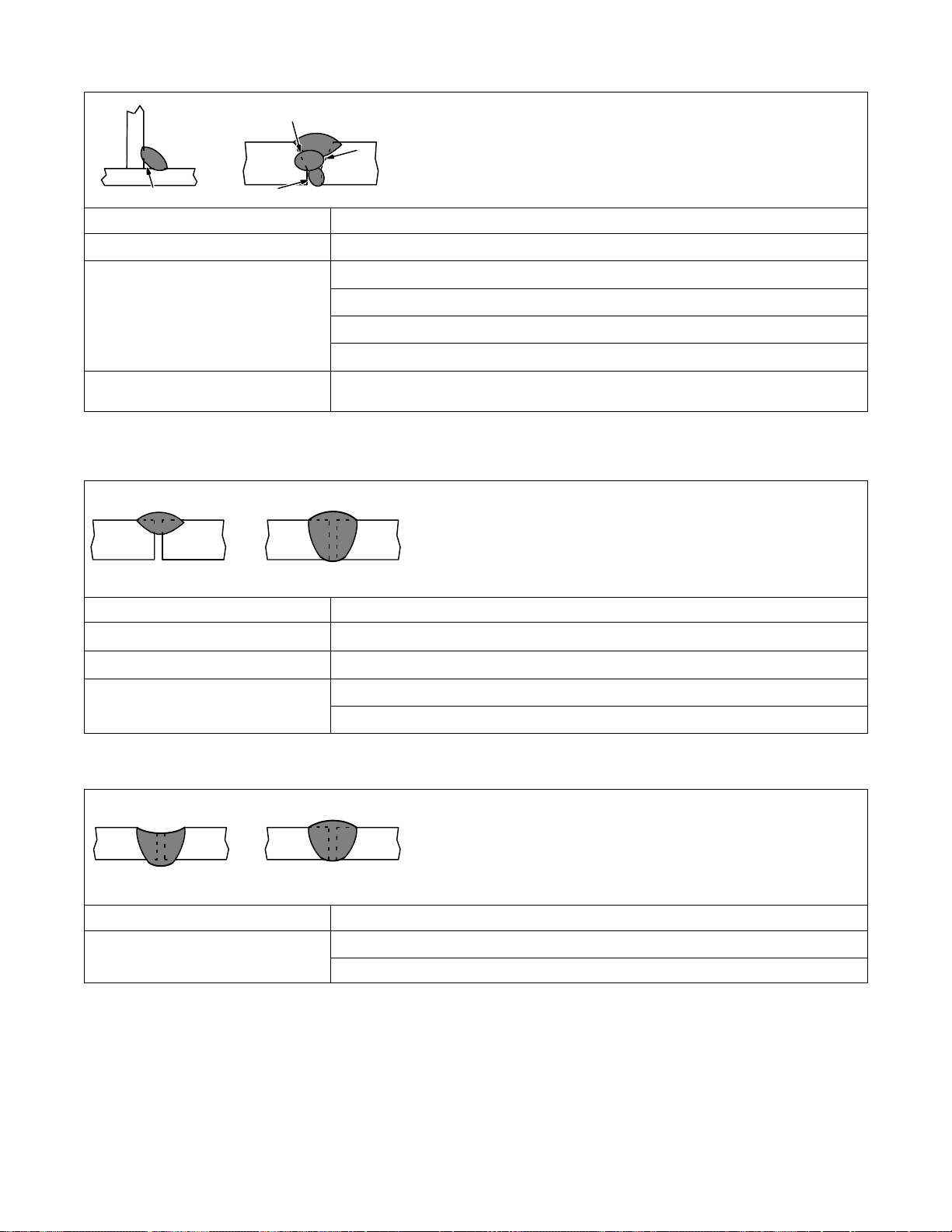
9-16. Troubleshooting – Incomplete Fusion
Incomplete Fusion – failure of weld metal to fuse completely with
base metal or a preceeding weld bead.
Possible Causes Corrective Actions
Insufficient heat input. Increase amperage. Select larger electrode and increase amperage.
Improper welding technique. Place stringer bead in proper location(s) at joint during welding.
Adjust work angle or widen groove to access bottom during welding.
Momentarily hold arc on groove side walls when using weaving technique.
Keep arc on leading edge of weld puddle.
Workpiece dirty. Remove all grease, oil, moisture, rust, paint, coatings, slag, and dirt from work surface before
welding.
9-17. Troubleshooting – Lack Of Penetration
Lack Of Penetration – shallow fusion between weld metal and
base metal.
Lack of Penetration Good Penetration
Possible Causes Corrective Actions
Improper joint preparation. Material too thick. Joint preparation and design must provide access to bottom of groove.
Improper weld technique. Keep arc on leading edge of weld puddle.
Insufficient heat input. Increase amperage. Select larger electrode and increase amperage.
Reduce travel speed.
9-18. Troubleshooting – Excessive Penetration
Excessive Penetration – weld metal melting through base metal and
hanging underneath weld.
Excessive Penetration
Possible Causes Corrective Actions
Excessive heat input. Select lower amperage. Use smaller electrode.
OM-355 Page 34
Good Penetration
Increase and/or maintain steady travel speed.
Page 39
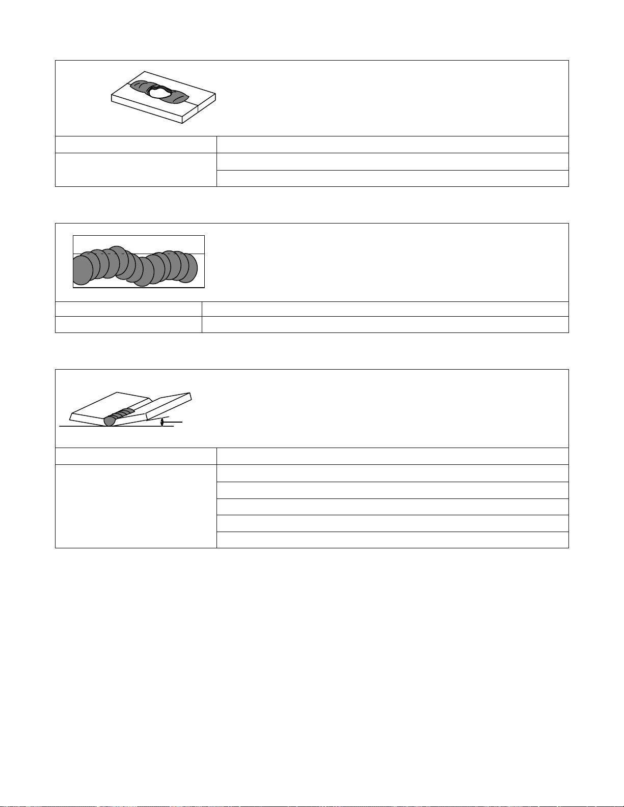
9-19. Troubleshooting – Burn-Through
Burn-Through – weld metal melting completely through base metal resulting
in holes where no metal remains.
Possible Causes Corrective Actions
Excessive heat input. Select lower amperage. Use smaller electrode.
Increase and/or maintain steady travel speed.
9-20. Troubleshooting – Waviness Of Bead
Waviness O f Bead – weld metal that is not parallel and does not cover
joint formed by base metal.
Possible Causes Corrective Actions
Unsteady hand. Use two hands. Practice technique.
9-21. Troubleshooting – Distortion
Distortion – contraction of weld met-
al during welding that forces base
metal t o move.
Base metal moves
in the direction of
the weld bead.
Possible Causes Corrective Actions
Excessive heat input. Use restraint (clamp) to hold base metal in position.
Make tack welds along joint before starting welding operation.
Select lower amperage for electrode.
Increase travel speed.
Weld in small segments and allow cooling between welds.
OM-355 Page 35
Page 40

SECTION 10 – PARTS LIST
29
28
30
27
21
20
19
7
18
22
17
26
24
16
25
14
15
13
12
11
23
9
8
31
32
33
34
35
36
6
. Hardware is common and
not available unless listed.
OM-355 Page 36
41
37
38
42
39
ST-802 252-D
43
10
5
4
3
2
1
40
Figure 10-1. Main Assembly
Page 41

Item
No.
Dia.
Mkgs.
Part
No.
Description Quantity
Figure 10-1. Main Assembly
+ 1 188 270 COVER, top 1. . . . . . . . . . . . . . . . . . . . . . . . . . . . . . . . . . . . . . . . . . . . . . . . . . . . . . . . . . . . . . . . . . . .
2 T4 190 332 COIL, coupling 1. . . . . . . . . . . . . . . . . . . . . . . . . . . . . . . . . . . . . . . . . . . . . . . . . . . . . . . . . . . . . . . .
3 190 436 HOLDER, HF coil 1. . . . . . . . . . . . . . . . . . . . . . . . . . . . . . . . . . . . . . . . . . . . . . . . . . . . . . . . . . . . . . . . .
4 G1 199 854 SPARK GAP ASSEMBLY (consisting of) 1. . . . . . . . . . . . . . . . . . . . . . . . . . . . . . . . . . . . . . . . .
199 855 BASE 1. . . . . . . . . . . . . . . . . . . . . . . . . . . . . . . . . . . . . . . . . . . . . . . . . . . . . . . . . . . . . . . . . . . . . . . . . . . . . . .
199 856 HOLDER 4. . . . . . . . . . . . . . . . . . . . . . . . . . . . . . . . . . . . . . . . . . . . . . . . . . . . . . . . . . . . . . . . . . . . . . . . . . . .
196 455 POINTS 4. . . . . . . . . . . . . . . . . . . . . . . . . . . . . . . . . . . . . . . . . . . . . . . . . . . . . . . . . . . . . . . . . . . . . . . . . . . . .
5 C3 201 197 CAPACITOR, polyp met film .002uf 4400 VAC 1. . . . . . . . . . . . . . . . . . . . . . . . . . . . . . . . . . . . .
6 T3 074 398 XFMR, high voltage 115 v pri 3600 v sec 1. . . . . . . . . . . . . . . . . . . . . . . . . . . . . . . . . . . . . . . . .
7 R8 188 067 RESISTOR, WW fxd 100w 200 ohm 1. . . . . . . . . . . . . . . . . . . . . . . . . . . . . . . . . . . . . . . . . . . . .
8 C18, 19 191 944 CAPACITOR, polyp met film 10uf 2. . . . . . . . . . . . . . . . . . . . . . . . . . . . . . . . . . . . . . . . . . .
9 188 369 HF BOX 1. . . . . . . . . . . . . . . . . . . . . . . . . . . . . . . . . . . . . . . . . . . . . . . . . . . . . . . . . . . . . . . . . . . . . . . . . .
10 190 514 HOLDER, HF coil slide 1. . . . . . . . . . . . . . . . . . . . . . . . . . . . . . . . . . . . . . . . . . . . . . . . . . . . . . . . . . . .
+ 11 192 828 LABEL 1. . . . . . . . . . . . . . . . . . . . . . . . . . . . . . . . . . . . . . . . . . . . . . . . . . . . . . . . . . . . . . . . . . . . . . . .
12 188 272 FRAME, lifting 1. . . . . . . . . . . . . . . . . . . . . . . . . . . . . . . . . . . . . . . . . . . . . . . . . . . . . . . . . . . . . . . . . . .
13 T1 188 283 XFMR, power main 208/230 1. . . . . . . . . . . . . . . . . . . . . . . . . . . . . . . . . . . . . . . . . . . . . . . . . . .
TP1, 2 020 520 THERMOSTAT, NC open 135C w/insulator 2. . . . . . . . . . . . . . . . . . . . . . . . . . . . . . . . . . . . . . .
PLG1 202 119 Connector W/Sockets 1. . . . . . . . . . . . . . . . . . . . . . . . . . . . . . . . . . . . . . . . . . . . . . . . . . . . . . . . . . .
PLG7 202 116 Connector W/Sockets 1. . . . . . . . . . . . . . . . . . . . . . . . . . . . . . . . . . . . . . . . . . . . . . . . . . . . . . . . . . .
PLG8 202 117 Connector W/Sockets 1. . . . . . . . . . . . . . . . . . . . . . . . . . . . . . . . . . . . . . . . . . . . . . . . . . . . . . . . . . .
PLG11 202 118 Connector W/Sockets 1. . . . . . . . . . . . . . . . . . . . . . . . . . . . . . . . . . . . . . . . . . . . . . . . . . . . . . . . . . .
14 190 341 HEAT SINK, rectifier 1. . . . . . . . . . . . . . . . . . . . . . . . . . . . . . . . . . . . . . . . . . . . . . . . . . . . . . . . . . . . . .
15 R1 186 468 RESISTOR, WW fxd 100w 50 ohm 1. . . . . . . . . . . . . . . . . . . . . . . . . . . . . . . . . . . . . . . . . . . . .
16 188 367 BRACKET, rectifier 1. . . . . . . . . . . . . . . . . . . . . . . . . . . . . . . . . . . . . . . . . . . . . . . . . . . . . . . . . . . . . . .
17 MOD1, 2 192 105 THYRISIT OR, SCR module 95A 400V 150C dual 2. . . . . . . . . . . . . . . . . . . . . . . . . . . .
18 190 343 BUS BAR, rectifier 1. . . . . . . . . . . . . . . . . . . . . . . . . . . . . . . . . . . . . . . . . . . . . . . . . . . . . . . . . . . . . . . .
19 190 342 BUS BAR, rectifier 1. . . . . . . . . . . . . . . . . . . . . . . . . . . . . . . . . . . . . . . . . . . . . . . . . . . . . . . . . . . . . . . .
20 HD1 191 941 TRANSDUCER, current hall effect 1. . . . . . . . . . . . . . . . . . . . . . . . . . . . . . . . . . . . . . . . . . . . .
21 C7, 8, 9, 10 190 460 CAPACITOR ASSEMBLY 2. . . . . . . . . . . . . . . . . . . . . . . . . . . . . . . . . . . . . . . . . . . . .
22 D1 192 116 MODULE, diode 1. . . . . . . . . . . . . . . . . . . . . . . . . . . . . . . . . . . . . . . . . . . . . . . . . . . . . . . . . . . . . . .
23 C1 191 944 CAPACITOR, polyp met film 10uf 1. . . . . . . . . . . . . . . . . . . . . . . . . . . . . . . . . . . . . . . . . . . . . . .
24 189 132 RESISTOR ASSEMBLY 1. . . . . . . . . . . . . . . . . . . . . . . . . . . . . . . . . . . . . . . . . . . . . . . . . . . . . . . . . . .
25 TP3 194 363 THERMOSTAT, NC open 150F close 125F 1. . . . . . . . . . . . . . . . . . . . . . . . . . . . . . . . . . . . .
26 133 873 VALVE, 24VDC 2way 1. . . . . . . . . . . . . . . . . . . . . . . . . . . . . . . . . . . . . . . . . . . . . . . . . . . . . . . . . . . . .
27 188 268 PANEL, rear 1. . . . . . . . . . . . . . . . . . . . . . . . . . . . . . . . . . . . . . . . . . . . . . . . . . . . . . . . . . . . . . . . . . . . .
28 604 102 CONNECTOR, clamp cable .690/1.070 1. . . . . . . . . . . . . . . . . . . . . . . . . . . . . . . . . . . . . . . . . . . . . .
29 190 442 CORD SET, 250V 8/3 10 ft 1. . . . . . . . . . . . . . . . . . . . . . . . . . . . . . . . . . . . . . . . . . . . . . . . . . . . . . . .
30 188 366 PLENUM 1. . . . . . . . . . . . . . . . . . . . . . . . . . . . . . . . . . . . . . . . . . . . . . . . . . . . . . . . . . . . . . . . . . . . . . . .
31 150 783 BLADE, fan 9 in 5wg 39deg .312 bore cw 1. . . . . . . . . . . . . . . . . . . . . . . . . . . . . . . . . . . . . . . . . . . .
32 188 706 MOTOR, fan 230V 50/60Hz 1550 RPM 1. . . . . . . . . . . . . . . . . . . . . . . . . . . . . . . . . . . . . . . . . . . . . .
33 187 807 BRACKET, fan motor mtg 1. . . . . . . . . . . . . . . . . . . . . . . . . . . . . . . . . . . . . . . . . . . . . . . . . . . . . . . . .
+ 34 188 362 PANEL, side right 1. . . . . . . . . . . . . . . . . . . . . . . . . . . . . . . . . . . . . . . . . . . . . . . . . . . . . . . . . . . . . .
35 188 269 BASE 1. . . . . . . . . . . . . . . . . . . . . . . . . . . . . . . . . . . . . . . . . . . . . . . . . . . . . . . . . . . . . . . . . . . . . . . . . . .
36 Z1 188 284 STABILIZER 1. . . . . . . . . . . . . . . . . . . . . . . . . . . . . . . . . . . . . . . . . . . . . . . . . . . . . . . . . . . . . . . . .
37 S5 187 467 SWITCH, polarity/changeover 1. . . . . . . . . . . . . . . . . . . . . . . . . . . . . . . . . . . . . . . . . . . . . . . . . .
38 C13, 14 188 964 CAPACITOR ASSEMBLY 2. . . . . . . . . . . . . . . . . . . . . . . . . . . . . . . . . . . . . . . . . . . . . . . .
39 Figure 10-2 PANEL, front w/components 1. . . . . . . . . . . . . . . . . . . . . . . . . . . . . . . . . . . . . . . . . . . . . . . . . . . .
40 188 271 PANEL, side left 1. . . . . . . . . . . . . . . . . . . . . . . . . . . . . . . . . . . . . . . . . . . . . . . . . . . . . . . . . . . . . . . . . .
41 141 162 HOUSING PLUG AND PINS (service kit) 0. . . . . . . . . . . . . . . . . . . . . . . . . . . . . . . . . . . . . . . . . . . .
42 155 552 CONNECTOR, torch (service kit) 0. . . . . . . . . . . . . . . . . . . . . . . . . . . . . . . . . . . . . . . . . . . . . . . . . . .
43 134 460 CONNECTOR, work cable (service kit) 0. . . . . . . . . . . . . . . . . . . . . . . . . . . . . . . . . . . . . . . . . . . . . .
44 134 327 LABEL, warning general precautionary 1. . . . . . . . . . . . . . . . . . . . . . . . . . . . . . . . . . . . . . . . . . . . . .
45 185 759 LABEL, warning electric shock 1. . . . . . . . . . . . . . . . . . . . . . . . . . . . . . . . . . . . . . . . . . . . . . . . . . . . .
OM-355 Page 37
Page 42

Item
No.
Dia.
Mkgs.
Part
No.
Description Quantity
Figure 10-1. Main Assembly (continued)
188 859 ACCESSORY KIT (consisting of) 1. . . . . . . . . . . . . . . . . . . . . . . . . . . . . . . . . . . . . . . . . . . . . . . . . . . . . . .
043 554 RFCS-14, foot control 1. . . . . . . . . . . . . . . . . . . . . . . . . . . . . . . . . . . . . . . . . . . . . . . . . . . . . . . . . . . . . . . . .
DB1712RDI TORCH, TIG 150A 12.5 ft cable 1. . . . . . . . . . . . . . . . . . . . . . . . . . . . . . . . . . . . . . . . . . . . . . . . . . . . .
188 860 WORK CABLE, w/clamp 1. . . . . . . . . . . . . . . . . . . . . . . . . . . . . . . . . . . . . . . . . . . . . . . . . . . . . . . . . . . . . .
193 094 KIT, regulator/hose 1. . . . . . . . . . . . . . . . . . . . . . . . . . . . . . . . . . . . . . . . . . . . . . . . . . . . . . . . . . . . . . . . . . .
176 840 HOLDER, electorde w/cable & dinse connector 1. . . . . . . . . . . . . . . . . . . . . . . . . . . . . . . . . . . . . . . . . . .
+When ordering a component originally displaying a precautionary label, the label should also be ordered.
To maintain the factory original performance of your equipment, use only Manufacturer’s Suggested
Replacement Parts. Model and serial number required when ordering parts from your local distributor.
OM-355 Page 38
Page 43

. Hardware is common and
not available unless listed.
3
7
4
2
1
13
4
14
12
11
5
6
8
9
10
ST-802 254-A
Figure 10-2. Panel, Front w/Components
Item
No.
Dia.
Mkgs.
Part
No.
Description Quantity
Figure 10-2. Panel, Front w/Components (Figure 10-1 Item 39)
1 174 991 KNOB, pointer 1. . . . . . . . . . . . . . . . . . . . . . . . . . . . . . . . . . . . . . . . . . . . . . . . . . . . . . . . . . . . . . . . . . . .
2 NAMEPLATE, (order by model and serial number) 1. . . . . . . . . . . . . . . . . . . . . . . . . . . . . . . . . . . . . . . . . . . . . .
3 RC7 143 976 RECEPTACLE W/ SOCKETS 1. . . . . . . . . . . . . . . . . . . . . . . . . . . . . . . . . . . . . . . . . . . . . . . . . .
4 186 092 RECPT KIT, Din style 1. . . . . . . . . . . . . . . . . . . . . . . . . . . . . . . . . . . . . . . . . . . . . . . . . . . . . . . . . . . . . .
5 192 451 COVER, LED diffuser 1. . . . . . . . . . . . . . . . . . . . . . . . . . . . . . . . . . . . . . . . . . . . . . . . . . . . . . . . . . . . . .
6 PC1 190 772 CIRCUIT CARD ASSEMBLY, control w/ hardware 1. . . . . . . . . . . . . . . . . . . . . . . . . . . . . . . .
PLG3 115 092 CONNECTOR & SOCKETS 1. . . . . . . . . . . . . . . . . . . . . . . . . . . . . . . . . . . . . . . . . . . . . . . . . . . . .
PLG6 115 091 CONNECTOR & SOCKETS 1. . . . . . . . . . . . . . . . . . . . . . . . . . . . . . . . . . . . . . . . . . . . . . . . . . . . .
PLG20 115 093 CONNECTOR & SOCKETS 1. . . . . . . . . . . . . . . . . . . . . . . . . . . . . . . . . . . . . . . . . . . . . . . . . . . .
PLG10 131 052 CONNECTOR & SOCKETS 1. . . . . . . . . . . . . . . . . . . . . . . . . . . . . . . . . . . . . . . . . . . . . . . . . . .
7 192 279 ENCLOSURE, circuit card assembly 1. . . . . . . . . . . . . . . . . . . . . . . . . . . . . . . . . . . . . . . . . . . . . . . . .
8 111 634 CAPACITOR ASSEMBLY 1. . . . . . . . . . . . . . . . . . . . . . . . . . . . . . . . . . . . . . . . . . . . . . . . . . . . . . . . . . .
9 S1 128 755 SWITCH, tgl DPST 40A 600VAC 1. . . . . . . . . . . . . . . . . . . . . . . . . . . . . . . . . . . . . . . . . . . . . . . .
10 C5, 6 188 273 PANEL, front 1. . . . . . . . . . . . . . . . . . . . . . . . . . . . . . . . . . . . . . . . . . . . . . . . . . . . . . . . . . . . .
11 175 952 PLASTIC, handle switch 1. . . . . . . . . . . . . . . . . . . . . . . . . . . . . . . . . . . . . . . . . . . . . . . . . . . . . . . . . . .
12 169 136 PIN, handle 1. . . . . . . . . . . . . . . . . . . . . . . . . . . . . . . . . . . . . . . . . . . . . . . . . . . . . . . . . . . . . . . . . . . . . .
13 174 992 KNOB, pointer .840 DIA x .250 ID 1. . . . . . . . . . . . . . . . . . . . . . . . . . . . . . . . . . . . . . . . . . . . . . . . . .
14 185 703 RECEPTACLE, Twistlock assembly 1. . . . . . . . . . . . . . . . . . . . . . . . . . . . . . . . . . . . . . . . . . . . . . . . .
+When ordering a component originally displaying a precautionary label, the label should also be ordered.
To maintain the factory original performance of your equipment, use only Manufacturer’s Suggested
Replacement Parts. Model and serial number required when ordering parts from your local distributor.
OM-355 Page 39
Page 44

Page 45

Page 46

Page 47

Warranty Questions?
Call
1-877-HOBART1
for your local
Hobart distributor.
Service
Y ou always get the fast,
reliable response you
need. Most replacement
parts can be in your
hands in 24 hours.
Support
Need fast answers to the
tough welding questions?
Contact your distributor or
call 1-800-332-3281. The
expertise of the distributor
and Hobart is there to
help you, every step of
the way.
Effective January 1, 2000
(Equipment with a serial number preface of “LA” or newer)
This limited warranty supersedes all previous Hobart warranties and is exclusive with no other
LIMITED WARRANTY – Subject to the terms and conditions
below, Hobart Welding Products., Troy, Ohio, warrants to its
original ret a i l p urchaser that new Hobart equipment sold after
the effective date of this limited warranty is free of defects in
material and workmanship at the time it is shipped by Hobart.
THIS WARRANTY IS EXPRESSL Y IN LIEU OF ALL OTHER
WARRANTIES, EXPRESS OR IMPLIED, INCLUDING THE
WARRANTIES OF MERCHANTABILITY AND FITNESS.
Within the warranty periods listed below, Hobart will repair or
replace any warranted parts or components that fail due to
such defects in material or workmanship. Hobart must be
notified in writing within thirty (30) days of such defect or
failure, at which time Hobart will provide instructions on the
warranty claim procedures to be followed.
Hobart shall honor warranty claims on warranted equipment
listed below in the event of such a failure within the warranty
time periods. All warranty time periods start on the date that
the equipment was delivered to the original retail purchaser, or
one year after the equipment is sent to a North American
distributor or e i ghteen months after the equipment is sent to an
International distributor.
1. 5 Years Parts – 3 Years Labor
* Original main power rectifiers
* Inverters (input and output rectifiers only)
2. 3 Years — Parts and Labor
* Transformer/Rectifier Power Sources
* Plasma Arc Cutting Power Sources
* Semi-Automatic and Automatic Wire Feeders
* Inverter Power Supplies
* Intellitig
* Engine Driven Welding Generators
(NOTE: Engines are warranted separately by
the engine manufacturer .)
3. 1 Year — Parts and Labor
* DS-2 Wire Feeder
* Motor Driven Guns (w/exception of Spoolmate
185 & Spoolmate 250)
* Process Controllers
* Positioners and Controllers
* Automatic Motion Devices
* RFCS Foot Controls
* Induction Heating Power Sources
* Water Coolant Systems
* HF Units
* Grids
* Maxstar 140
* Spot Welders
* Load Banks
* Hobart Cyclomatic Equipment
* Running Gear/Trailers
* Plasma Cutting Torches (except APT & SAF
Models)
* Field Options
(NOTE: Field options are covered under True
Blue for the remaining warranty period of the
product they are installed in, or for a minimum of
one year — whichever is greater.)
4. 6 Months — Batteries
5. 90 Days — Parts
* MIG Guns/TIG Torches
* Induction Heating Coils and Blankets
guarantees or warranties expressed or implied.
* APT, ZIPCUT & PLAZCUT Model Plasma Cutting
Torches
* Remote Controls
* Accessory Kits
* Replacement Parts (No labor)
* Spoolmate 185 & Spoolmate 250
* Canvas Covers
HOBART’s Limited Warranty shall not apply to:
1. Consumable components; such as contact tips,
cutting nozzles, contactors, brushes, slip rings,
relays or parts that fail due to normal wear.
2. Items furnished by Hobart, but manufactured by others,
such as engines or trade accessories. These items are
covered by the manufacturer’s warranty, if any.
3. Equipment that has been modified by any party other
than Hobart, or equipment that has been improperly
installed, improperly operated or misused based upon
industry standards, or equipment which has not had
reasonable and necessary maintenance, or equipment
which has been used for operation outside of the
specifications for the equipment.
HOBART PRODUCTS ARE INTENDED FOR PURCHASE
AND USE BY COMMERCIAL/INDUSTRIAL USERS AND
PERSONS TRAINED AND EXPERIENCED IN THE USE
AND MAINTENANCE OF WELDING EQUIPMENT.
In the event of a warranty claim covered by this warranty, the
exclusive remedies shall be, at Hobart’s option: (1) repair; or
(2) replacement; or, where authorized in writing by Hobart in
appropriate cases, (3) the reasonable cost of repair or
replacement at an authorized Hobart service station; or (4)
payment of or credit for the purchase price (less reasonable
depreciation bas e d u p o n actual use) upon return of the goods
at customer’s risk and expense. Hobart’s option of repair or
replacement will be F .O.B., Factory at Appleton, Wisconsin, or
F.O.B. at a Hobart authorized service facility as determined by
Hobart. Therefore no compensation or reimbursement for
transportation costs of any kind will be allowed.
TO THE EXTENT PERMITTED BY LAW, THE REMEDIES
PROVIDED HEREIN ARE THE SOLE AND EXCLUSIVE
REMEDIES. IN NO EVENT SHALL HOBART BE LIABLE
FOR DIRECT, INDIRECT, SPECIAL, INCIDENTAL OR
CONSEQUENTIAL DAMAGES (INCLUDING LOSS OF
PROFIT), WHETHER BASED ON CONTRACT, TORT OR
ANY OTHER LEGAL THEORY.
ANY EXPRESS WARRANTY NOT PROVIDED HEREIN
AND ANY IMPLIED WARRANTY, GUARANTY OR
REPRESENTATION AS TO PERFORMANCE, AND ANY
REMEDY FOR BREACH OF CONTRACT TORT OR ANY
OTHER LEGAL THEORY WHICH, BUT FOR THIS
PROVISION, MIGHT ARISE BY IMPLICATION,
OPERATION OF LAW, CUSTOM OF TRADE OR COURSE
OF DEALING, INCLUDING ANY IMPLIED WARRANTY OF
MERCHANTABILITY OR FITNESS FOR PARTICULAR
PURPOSE, WITH RESPECT TO ANY AND ALL
EQUIPMENT FURNISHED BY HOBART IS EXCLUDED
AND DISCLAIMED BY HOBART.
Some states in the U.S.A. do not allow limitations of how long
an implied warranty lasts, or the exclusion of incidental,
indirect, special or consequential damages, so the above
limitation or exclusion may not apply to you. This warranty
provides specific legal rights, and other rights may be
available, but may vary from state to state.
In Canada, legislation in some provinces provides for certain
additional warranties or remedies other than as stated herein,
and to the extent that they may not be waived, the limitations
and exclusions set out above may not apply. This Limited
Warranty provides specific legal rights, and other rights may
be available, but may vary from province to province.
hobart standard 7/00
Page 48

Owner’s Record
Please complete and retain with your personal records.
Model Name Serial/Style Number
Purchase Date (Date which equipment was delivered to original customer.)
Distributor
Address
City
State Zip
Resources Available
Always provide Model Name and Serial/Style Number.
To locate a Distributor,
retail or service location:
Call 1-877-Hobart1 or visit our website at
www.HobartWelders.com
For technical assistance:
Call 1-800-332-3281
Contact the Delivering Carrier for:
For assistance in filing or settling claims,
contact your distributor and/or equipment
manufacturer’s Transportation Department.
Contact your Distributor for:
Welding Supplies and Consumables
Options and Accessories
Personal Safety Equipment
Service and Repair
Replacement Parts
Training (Schools, Videos, Books)
Technical Manuals (Servicing Information
and Parts)
Circuit Diagrams
Welding Process Handbooks
File a claim for loss or damage during
shipment.
Hobart Welding Products
An Ill inoi s Tool Works Company
600 West Main Street
Troy, OH 45373 USA
For Technical Assistance:
Call1-800-332-3281
For Literature Or Nearest Dealer:
Call 1-877-Hobart1
PRINTED IN USA 2000 Hobart Welding Products. 1/00
 Loading...