

Hobart 60SE200 Operation And Maintenance Manual
OM-2155
071406 – Original
060707 – Revision 3
Operation and Maintenance Manual
Model: 60SE200
60 kVA, 3 Phase, 115/200 Volt,
400 Hz. Solid State Frequency Converter
Series 500381
ITW GSE Group
Hobart Ground Power
Troy, Ohio 45373
U.S.A.


Data Sheet 165
Warranty
1. Hobart Brothers Company (hereinafter called HOBART) warrants that each new and unused Hobart Ground Power
Equipment, (hereinafter called the PRODUCT) is of good workmanship and is free from mechanical defects,
provided that (1) the PRODUCT is installed and operated in accordance with the printed instructions of HOBART,
(2) the PRODUCT is used under the normal operating conditions for which it is designed, (3) the PRODUCT is not
subjected to misuse, negligence or accident, and (4) the PRODUCT receives proper care, lubrication, protection,
and maintenance under the supervision of trained personnel.
2. This warranty expires 15 months after shipment by HOBART to the first user, or 12 months after installation,
whichever first occurs.
3. This warranty does not apply to: primary and secondary switch contacts, cable connectors, carbon brushes, fuses,
bulbs, and filters unless found to be defective prior to use.
4. Hobart DOES NO T WARRANT THE FOLLOWING COMPONENTS: Engines, engine components; such as:
starters, alternators, regulators, governors, etc., and cable retrieving devices. Many of the foregoing components
are warranted directly by the manufacturer to the first user and se rviced by a worldwide network of distributors and
others authorized to handle claims for component manufacturers. A first user’s claim should be presented directly
to such an authorized component service outlet. In the event any component manufacturer has warranted its
component to HOBART and will not deal directly with a first user then HOBART will cooperate with the first user
in the presentation of a claim to such manufacturer. Under NO circumstances does HOBART assume any liability
for any warranty cl aim against or warranty work done by or in behalf of any manufacturer of the foregoing
components.
5. This warranty is extended by HOBART only to the purchaser of new PRODUCTS from HOBART or one of its
authorized distributors. The PRODUCTS purchased under thi s warranty are intended for use exclusively by the
buyer and his employees and by no other persons and, therefore, there shall be no third party beneficiary to this
warranty.
6. A claim of defects in any PRODUCT covered by this warranty is subject to HOBART f actory inspection and
judgment. HOBART’S liability is limited to repair of any defects found by HOBART to exist, or at HOBART’S
option the replacement of the defective product, F.O.B. factory, after the defective product has been returned by the
purchaser at its expense to HOBART’S shipping place. Replacement and exchange parts will be warranted for the
remainder of the original Warranty, or for a period of ninety (90) days, whichever is greater.
7. UNDER NO CIRCUMSTANCES whatsoever shall HOBART and its authorized distributors be liable for any
special or consequential damages, whether based on lost goodwill, lost resale profits, work stoppage impairment
of other goods or otherwise, and whether arising out of breach of any express or implied warranty, breach of
contract, negligence or otherwise, except only in the case of personal injury as may be required by applicable law.
8. Continued use of the PRODUCT(S) after discovery of a defect VOIDS ALL WARRANTIES.
9. Except as authorized in writing, this warranty does not cover any equipment that has been altered by any party
other than HOBART.
10. THERE ARE NO WARRANTIES WHICH EXTEND BEYOND THE DESCRIPTION ON THE FACE HERE
OF. HOBART MAKES NO WARRANTIES, EXPRESSED OR IMPLIED, OF MERCHANTABILITY OR
FITNESS FOR A PARTICULAR PURPOSE.
11. HOBART neither assumes nor authorizes any person to assume for HOBART any liability in connection with the
PRODUCTS sold, and there are no oral agreements or warranties collateral to or affecting this written
Warranty. This warranty and all undertakings of HOBART thereunder shall be governed by the laws of the State
of Ohio, United States of America.
HOBART GROUND POWER
TROY, OHIO 45373
Index: 990223
Replaces: 980601
WARNING AT ALL TIMES, SAFETY MUST BE CONSIDERED AN IMPORTANT FACTOR IN THE
INSTALLATION, SERVICING AND OPERATION OF THE PRODUCT, AND SKILLED, TECHNICALLY
QUALIFIED PERSONNEL SHOULD ALWAYS BE EMPLOYED FOR SUCH TASKS.


OM-2155 / Operation and Maintenance Manual
60 kVA PoWerMaster EV / Series 500381 / Solid State Converter
Safety Warnings and Cautions
WARNING
IMPORTANT
1) How to read this manual
To avoid hazards the following safety instructions noted in this section and throughout the manual must be
followed to ensure personnel’s health and safety during installation, daily operation and during maintenance
interventions.
The PoWerMaster EV can be delivered with several optional features. Therefore, kindly refer to Appendix A
for information about the configuration of this particular equipment before installing, operating or performing
maintenance of the equipment.
2) General
Equipment that supplies electrical power can cause serious injury or death, or damage to other equipment or
property. The operator must strictly observe all safety rules and take precautionary actions. Safe practices
have been developed from past experience in the use of power source equipment. While certain practices
below apply only to electrically powered equipment, other practices apply to engine-driven equipment, and
some practices to both.
3) Installation and Shock Prevention
Bare conductors, terminals in the output circuit, or ungrounded, electrically live equipment can fatally shock a
person. Have a certified electrician verify that the equipment is adequately grounded and learn what
terminals and parts are electrically HOT. Avoid hot spots on machine. Use proper safety clothing,
procedures, and test equipment.
The electrical resistance of the body is decreased when wet, permitting dangerous currents to flow through it.
When inspecting or servicing equipment, do not work in damp areas. Stand on a dry rubber mat or dry wood,
and use insulating gloves when dampness or sweat cannot be avoided. Keep clothing dry, and ne ver work
alone.
a) General Installation and Grounding of Electrically Powered Equipment
This equipment must be installed and maintained in accordance with the National Electrical Code,
ANSI/NFPA 70, or other applicable codes. A power disconnect switch or circuit breaker must be
located at the equipment. Check the nameplate for voltage, frequency, and phase requirements. If
ELECTRIC SHOCK can KILL. Do not touch live electrical parts.
ELECTRIC ARC FLASH can injure eyes, burn skin, cause equipment damage, and
ignite combustible material. DO NOT use power cables to break load. Prevent tools
from causing short circuits.
IMPROPER PHASE CONNECTION, PARALLELING, OR USE can damage this and
attached equipment.
Protect all operating personnel. Read, understand, and follow all instructions in the
Operating/Instruction Manual before installing, operating, or servicing the equipment.
Keep the manual available for future use by all operators.
July 14, 2006 Safety Warnings
Page 1

OM-2155 / Operation and Maintenance Manual
60 kVA PoWerMaster EV / Series 500381 / Solid State Converter
only 3-phase power is available, connect any single-phase rated equipment to only two wires of the 3phase line. DO NOT CONNECT the equipment grounding conductor (lead) to the third live wire of
the 3-phase line, as this makes the equipment frame electrically HOT, which can cause a fatal shock.
Always connect the grounding lead, if supplied in a power line cable, to the grounded switch box or
building ground. If not provided, use a separate grounding lead. Ensure that the current (amperage)
capacity of the grounding lead will be adequate for the worst fault current situation. Refer to the
National Electrical Code ANSI/NFPA 70 for det ails. Do not remove plug ground prongs. Use
correctly mating receptacles.
b) Converter Installation safety instructions
Prior to the installation of this equipment, you should read all relevant chapters and sections within
this manual. Special attention must be given to Chapter 1, Section 3, which describes the
requirements for the building installation, the interlock safety system, short circuit protection and
minimum cable dimensions to get the maximum performance of the equipment.
For safety reasons the interlock cables must be connected in accordance to this manual. If the
interlock cables are not correctly mounted, this may cause hazard to operators, as the output plug
would then be left with voltage on, when the start push button has been pushed.
After installation of interlock cables, output cable(s) and plug(s), the phase sequence and the function
of the interlock system must be thoroughly checked prior to connection of any aircraft.
c) Output Cables and Terminals
Inspect cables frequently for damage to the insulation and the connectors. Replace or repair cracked
or worn cables immediately. Do not overload cables. Do not touch output terminal while equipment
is energized.
4) Operator safety instructions
The manual should be read thoroughly be fore operating equipment. The user will gain an overall
introduction of how to operate the equipment.
If the equipment is plugable at the input by means of an industrial plug and in the case that you are not
sure that the building installation complies with the requirements of the equipment to be connected,
please refer to the installation safety instructions or contact a qualified service technician. .
5) Service and Maintenance
Service personnel should study the complete manual carefully. It is important not only to be confident with
the equipment, but also to be aware of local health and safety rules applicable where the equipment is
installed.
This equipment must be maintained in good electrical condition to avoid hazards stemming from
disrepair. Report any equipment defect or safety hazard to the supervisor and discontinue use of the
equipment until its safety has been assured. Repairs should be made by qualified personnel only.
Before inspecting or servicing this equipment, take the following precautions:
a) Shut off all power at the disconnecting switch, or line breaker before inspecting or servicing the
equipment.
July 14, 2006 Safety Warnings
Page 2

OM-2155 / Operation and Maintenance Manual
60 kVA PoWerMaster EV / Series 500381 / Solid State Converter
b) Lock switch OPEN (or remove line fuses) so that power cannot be turned on accidentally.
c) Disconnect power to equipment if it is out of service.
d) If troubleshooting must be done with the unit energized, have another person present who is trained
in turning off the equipment and providing or calling for first aid.
6) Fire And Explosion Prevention
Fire and explosion are caused by electrical sho rt circuits, combustible material near this equipment, or
unsafe operating conditions. Overloaded or shorted equipment can become hot enough to cause fires by
self destruction or by causing nearby combustibles to ignite. For electrically powered equipment, provide
primary input protection to remove short circuited or heavily overloaded equipment from the line.
5) Bodily Injury Prevention
Serious injury can result from contact with fans or hot spots inside some equipment. Shut DOWN such
equipment for inspection and routine maintenance. When equipment is in operation, use extreme care in
doing necessary troubleshooting and adjustment. Do not remove guards while equipment is operating.
6) Medical and First Aid Treatment
First aid facilities and a qualified first aid person should be available for each shift for immediate treatment
of all injury victims. Electric shock victims should be checked by a physician and taken to a hospital
immediately if any abnormal signs are observed.
EMERGENCY
FIRST AID
Call physician immediately. Seek additional assistance. Use First Aid techniques
recommended by American Red Cross until medical help arrives.
IF BREATHING IS DIFFICULT, give oxygen, if available, and have victim lie down.
FOR ELECTRICAL SHOCK, turn off power. Remove victim; if not breathing, begin
artificial respiration, preferably mouth-to-mouth. If no detectable pulse, begin external
heart massage. ALWAYS CALL EMERGENCY RESCUE SQUAD IMMEDIATELY.
7) Equipment Precautionary Labels
Inspect all precautionary labels on the equipment monthly. Order and replace all labels that cannot be
easily read.
July 14, 2006 Safety Warnings
Page 3

OM-2155 / Operation and Maintenance Manual
60 kVA PoWerMaster EV / Series 500381 / Solid State Converter
This page intentionally left blank.
July 14, 2006 Safety Warnings
Page 4

OM-2155 / Operation and Maintenance Manual
60 kVA PoWerMaster EV / Series 500381 / Solid State Converter
Introduction
This manual contains operation and maintenance information for a PoWerMaster EV, 400 Hz Solid State
Frequency Converter manufactured by ITW GSE Group, Hobart Ground Power, Troy, Ohio 45373.
This manual is not intended to be a textbook on electricity or electronics. Its primary purpose is to provide
information and instructions to experienced operators, electricians, and mechanics who have never operated
this equipment. It is the intent of this manual to guide and assist operators and mai ntenance people in the
proper use and care of the equipment.
Use of the manual should not be put off until a trouble or need for help develops. Read the instructions
before starting the unit. Learn to use the manual and to locate information contained in it. Its style and
arrangement are very similar to commercial aircraft manuals.
The manual is divided into chapters . Each chapter is divided into as many sections as required.
In addition to operation and maintenance instructions, the manual contains an options list Appendix A, and a
collection of manufacturer’s literature and supplemental information in Chapter 4.
If you have any questions concerning your Hobart Ground Power equipment, immediately contact our Service
Department by mail, telephone, FA X, or E-Mail.
Write: ITW GSE Group
Hobart Ground Power
Service Department
1177 Trade Road East
Troy, Ohio 45373
U.S.A.
Call Inside U.S.A.: (800) 422 -4166 (Parts)
(800) 422 -4177 (Service)
Call From Foreign Countries: (937) 332-5050 (Parts)
(937) 332 -5060 (Service)
FAX Inside U.S.A. (800) 367 -4945
FAX From Foreign Countries: (937) 332-5121
E-Mail : service@itwgsegroup.com
Web Page : www.itwgsegroup.com
July 14 , 2006 Introduction
Page 1

OM-2155 / Operation and Maintenance Manual
60 kVA PoWerMaster EV / Series 500381 / Solid State Converter
This page intentionally left blank.
July 14 , 2006 Introduction
Page 2

OM-2155 / Operation and Maintenance Manual
60 kVA PoWerMaster EV / Series 500381 / Solid State Converter
Table of Contents
Chapter 1 Description / Operation Chapter- Section/Page#
Section 1
Section 2
Section 3
Section 4
Section 5
July 14 , 2006 Table of Contents
General Description 1-1/1
Technical Specifications 1-2/1
Standards 1-2/1
Electrical Specifications 1-2/1
Efficiency 1-2/1
Setup 1-2/2
Protections 1-2/2
Physical 1-2/2
Environmental 1-2/2
Life, Etc. 1-2/2
Preparation, Adjustment, Maintenance 1-3/1
Storage Before Installation 1-3/1
Operational and Environmental Conditions after Commissioning 1-3/1
Mounting of Bottom Filter 1-3/1
Connection of Cables 1-3/1
Setup of Parameters 1-3/4
Maintenance 1-3/6
Instruction for Use 1-4/1
Input Breaker 1-4/1
Emergency Stop 1-4/1
Control Panel 1-4/1
Display/Keyboard Interface 1-4/2
Setup of Parameters 1-3/4
Maintenance 1-3/6
Functional Description of Power Part 1-5/1
Input Breaker 1-5/1
Input Filter 1-5/1
12-Pulse Transformer / DC/AC Module 1-5/1
Isolation Transformer 1-5/2
Output Filter 1-5/2
Output Contactor 1-5/2
Page 1

OM-2155 / Operation and Maintenance Manual
60 kVA PoWerMaster EV / Series 500381 / Solid State Converter
Section 6
Functional Description of Electronic Part 1-6/1
Facilities 1-6/1
Composition of Processor Module and Interfaces 1-6/1
Chapter 2 Service/Troubleshooting Chapter- Section/Page#
Section 1
Error Diagnostics 2-1/1
Error Numbering / Groupin g 2-1/1
Display Readings / Causes / Suggestions 2-1/2
Listing of DC/AC Modules 2-1/26
Errors Related to Possible Options 2-1/27
Chapter 3 Overhaul/Major Repair Chapter- Section/Page#
Section 1
Overhaul/Major Repair 3-1/1
General 3-1/1
Service Information and Factory Repair 3-1/1
Workmanship 3-1/1
Converter Bridge Mount Removal and Installation 3-1/2
Component Removal and Replacement 3-1/4
PC Board Removal and Replacement 3-1/7
Chapter 4 Illustrated Parts List Chapter- Section/Page#
Section 1
Section 2
Introduction 4-1/1
General 4-1/1
Purpose 4-1/1
Arrangement 4-1/1
Explanation of Parts List 4-1/1
Manufacture's Codes 4-2/1
Explanation of Manufacture's (Vendor) Code List 4-2/1
July 14 , 2006 Table of Contents
Page 2

OM-2155 / Operation and Maintenance Manual
60 kVA PoWerMaster EV / Series 500381 / Solid State Converter
Section 3
Section 4
Illustrated Parts List 4-3/1
Explanation of Parts List Arrangement 4-3/1
Symbols and Abbreviations 4-3/1
Figure 1: General Assembly 4-3/2
Figure 2A: Transformer Section Assembly 4-3/4
Figure 2B: Transformer Section Assembly 4-3/6
Figure 3: Power Module Panel Assembly 4-3/8
Figure 4: Input/Output Panel Assembly 4-3/10
Figure 5: Cooling Fan Box Assembly 4-3/12
Figure 6: Control Panel Assembly 4-3/14
Figure 7: AC Filter Capacitor Bank Assembly 4-3/16
Figure 8: DC Filter Capacitor Bank Assembly 4-3/18
Figure 9: DC/AC and Rectifier Module Panel Assembly 4-3/20
Figure 10: Frame and Exterior Panel Components 4-3/22
Numerical Index 4-4/1
Explanation of Numerical Index 4-4/1
Chapter 5 Manufacture's Literature
Appendix A Options
Unusual Service Conditions
July 14 , 2006 Table of Contents
Page 3

OM-2155 / Operation and Maintenance Manual
60 kVA PoWerMaster EV / Series 500381 / Solid State Converter
This page intentionally left blank.
July 14 , 2006 Table of Contents
Page 4
OM-2155 / Operation and Maintenance Manual
Power
Electronic
60 kVA PoWerMaster EV / Series 500381 / Solid State Converter
Section 1 General Description
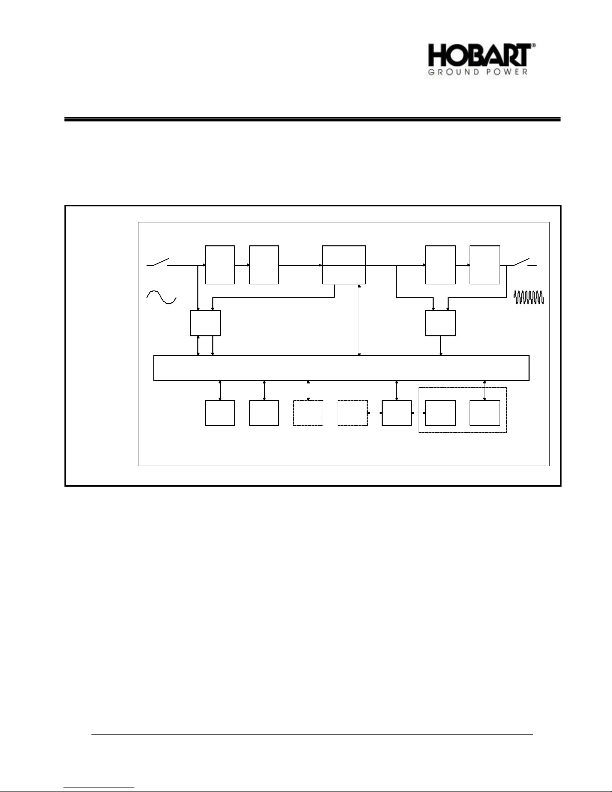
Figure 1 on which the following description is based shows the basic design principle. A detailed description
of the power part is found in Section 5 whereas the electronic part is described in Section 6.
The block diagram shows the power part and electronic part. The power modules and the power switch gear
make up the power part, whereas the electronic modules make up the electronic part.
Part
Part
Input Output
Input breaker
50/60 Hz
AUX
module
Input
filter
12-pulse
transformer
RS232RS485
Relay
module 2
DC/AC-module 1
DC/AC-module 2
Processor module
Remote
control
Relay
module 1
Isolation
transformer
Output feed
module
Control panel
Instrumen-
tation
Users operational zone
Output
filter
Display
Keyboard
module
Output
contactor(s)
400 Hz
Diagram and Design Principle
Figure 1
The input filter protects the convert er from mains transients. After the filtering, the three phases of the mains
are transformed into six phases which are then rectified in a non -regulated 12-pulse full bridge rectifier. The
combination of the 12 pulse rectifier, the related transformer an d the input filter ensures that harmonic feed
back into the mains is reduced to a minimum (i.e. no mains pollution/distortion).
An additional benefit provided by the 12 pulse rectifier is the soft start facility which limits the inrush currents
at the input to a value much lower than the converter’s nominal current.
The filtered DC-voltage supplies the inverter which generates a 3-phase 400 Hz system with a regulated
amplitude and a low harmonic content. The inverter technology is based on a Space Vector Pulse Width
Modulation (SV -PWM) concept which is an advanced type of the PWM technology. The SV-PWM system
provides the converter with extremely fast dynamic properties and a low distortion.
The isolation transformer secures galvanic separation betwee n the mains and the 400 Hz output.
July 14 , 2006 Chapter 1-1
Page 1

OM-2155 / Operation and Maintenance Manual
60 kVA PoWerMaster EV / Series 500381 / Solid State Converter
The converter has individual voltage regulation at each output phase. This secures a precise 400 Hz voltage
at the aircraft plug even in case of a high degree of unbalanced load and long cables. The harmonic content
of the output voltage is further reduced by means of an output filter resulting in a total distortion of less than
2%.
The processor module is based on a micro -controller and a digital signal processor (DSP), which together
regulate, supervise and diagnose external and internal faults. As soon as the converter is connected to the
mains, and constantly during normal operation, the processor module runs through a self-check program
which checks all internal functions. If an internal or external error is detected, the display shows the nature of
the error. All immediate parameters related to a shut-down are stored in the converter’s memory whereas up
to 1000 error situations can be stored.
July 14 , 2006 Chapter 1-1
Page 2

OM-2155 / Operation and Mainten ance Manual
60 kVA PoWerMaster EV / Series 500381 / Solid State Converter
Section 2 Technical Specifications
1) Standards
DFS 400 Specification for 400 Hz aircraft power supply.
ISO 6858 Aircraft ground support electrical supplies- General requirements
BS 2G 219 General requirements for ground support electrical supplies for aircraft
MIL-704E Aircraft electric power characteristics.
EN 50091 -1 General and safety requirements
EN 61000 -6-4 Electromagnetic compatibility, Generic emission standard
EN 61000 -6-2 Electromagnetic compatibility, Generic immunity standard
SAE ARP 5015 Ground equipment – 400 Hz ground power performance requirement
EN2282 Aerospace series characteristics of aircraft electrical supplies
2) Electrical Specifications
a) Input
Voltage: 3 x 460/480V ± 15% or according to customers specification.
Frequency: 50 / 60 Hz ± 5 %
Rectification: 12-pulse
Line Current : 75 A ± 15%
Max. Pre-fusing: 100 A
Line Current Distortion: < 10%
Power Factor: > 0. 96 at 100% load
Inrush current : None, soft start
Power interruption: Up to 20 ms
b) Output
Power: 60 kVA, P.F. = 0.8
Voltage: 3 x 200/115 V.
Power factor: 0.7 lagging to 0.95 leading.
Voltage regulation: < 0.5% for balanced load and 30% unbalanced load
Voltage transient recovery: ∆U < 8% and recovery time < 10 ms at 100% load change
Total harmonic content: < 2% at linear load (typically < 1.5%)
< 2% at non-linear load according to ISO 1540
Crest factor: 1.414 ± 3%
Voltage mo dulation: < 1.0% (typically< 0.5%)
Phase angle symmetry: 120° ± 1° for balanced load
120° ± 2° for 30% unbalanced load
Frequency: 400 Hz ± 0. 1%
Overload: 120% for 600 seconds
150% for 30 seconds
170% for 5 seconds
200% for 1 second
3) Efficiency
Overall efficiency: > 0.93 at 35-90 kVA load
Stand-by losses : < 50 W
No-load losses: < 1500 W
July 14, 2006 Chapter 1-2
Page 1

OM-2155 / Operation and Mainten ance Manual
60 kVA PoWerMaster EV / Series 500381 / Solid State Converter
4) Setup
Output voltage: 100-128 V
Voltage compensation: 0-9V (individual for each outlet)
Delay to stand -by: 0-15 min.
Time: Year, month, day, hour, minute and seconds
Interlock: Bypass on / off
Fan: Test on / off
Serial Protocol: 3964R or JBUS
Serial Port: RS232 or RS422/485
JBUS slave address: 1-247
Error log / Power log: Reset
Timer (hour counter): Reset
5) Protections
No Break Power Transfer
Input over -and under voltage
Input overload
Internal high temperature
Internal voltage error
Output over-and under voltage (according to DFS 400)
Overload at output
Short circuit at output
6) Physical
Weight
Fixed model: 1102 lbs (500 kg)
Bridge-mounted model: 1102 lbs (500 kg)
Mobile model: 1700 lbs (600 kg)
For dimensions, kindly refer to layout drawings enclosed under Chapter 5.
7) Environmental
Operating temperature: -40 °C to +52 °C
Relative humidity: 10-95%
Noise level: < 65 dB (A) at 1m, typically 60 dB(A)
Standard protection: IP55 (Electronic part)
8) Life, etc.
Operational life: Min 25 years
Mean time between failures (MTBF):
Converter: Min 25.000 hours
Ventilation system: Min. 100.000 hours
Mean time to repair (MTTR): Max. 20 min.
July 14, 2006 Chapter 1-2
Page 2
OM-2155 / Operation and Maintenance Manual
Ground Cable
60 kVA PoWerMaster EV / Series 500381 / Solid State Converter
Section 3 Preparation, Adjustment and Maintenance
1) Storage Before Installation
To secure optimal storage conditions prior to installation, it is recommended that the converter be stored
inside to protect it from rain and excessive humidity while it is left without power on.
Only equipment in seaworthy packing can be stored outside.
2) Operational and Environmental Conditions after Commissioning
When the converter has been installed and commissioned, we recommend that the input always be kept
with input po wer ON to provide optimal conditions for the electronic components and to avoid humidity in
the form of condensation from reaching vital parts.
If for some reason the converter has been without input voltage for a long period, a visual inspection
should be carried out. In case that condensation is discovered on any internal parts, the parts have to
dry out before input voltage is again applied.
3) Mounting of Bottom Filter (only valid for stationary/fixed models)
Due to transport safety, fixed models are delivered without the bottom filter mounted. The filter is
mounted in the hole (designated for fork -lifting) at the bottom by means of the accompanying mounting
devices.
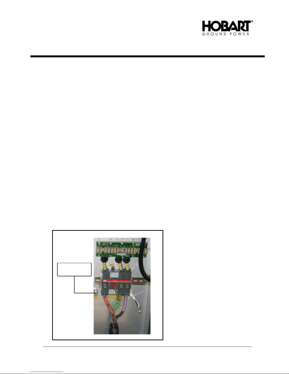
4) Connection of Cables
a) Input
Due to personal safety the converter most be protected by grounding of the PE terminal (Figure 1).
The converter should be pre-fused according to the table below:
PE Terminal
January 18, 2007
Revision 2
Input Cable Connections
Figure 1
Chapter 1-3
Page 1
OM-2155 / Operation and Maintenance Manual
60 kVA PoWerMaster EV / Series 500381 / Solid State Converter
kVA Rating Input Line Current Maximum pre -fuse
400 V 76 A ± 15%
460 V 66 A ± 15% 60
480 V 63 A ± 15%
Input Voltage Requirements
Figure 2
The three phases of the input voltage supply and the earth connection are connected to the terminals
labeled L1, L2, L3 and PE. As the phase sequence is of importance for the converter's function, the
phase sequence is checked by means of the built-in auto test (when input power is applied). If the
phase sequence is wrong, this is shown at the display. If wrong, the correction is made by changing
the two phases. All connection diagrams can be found in Chapter 5.
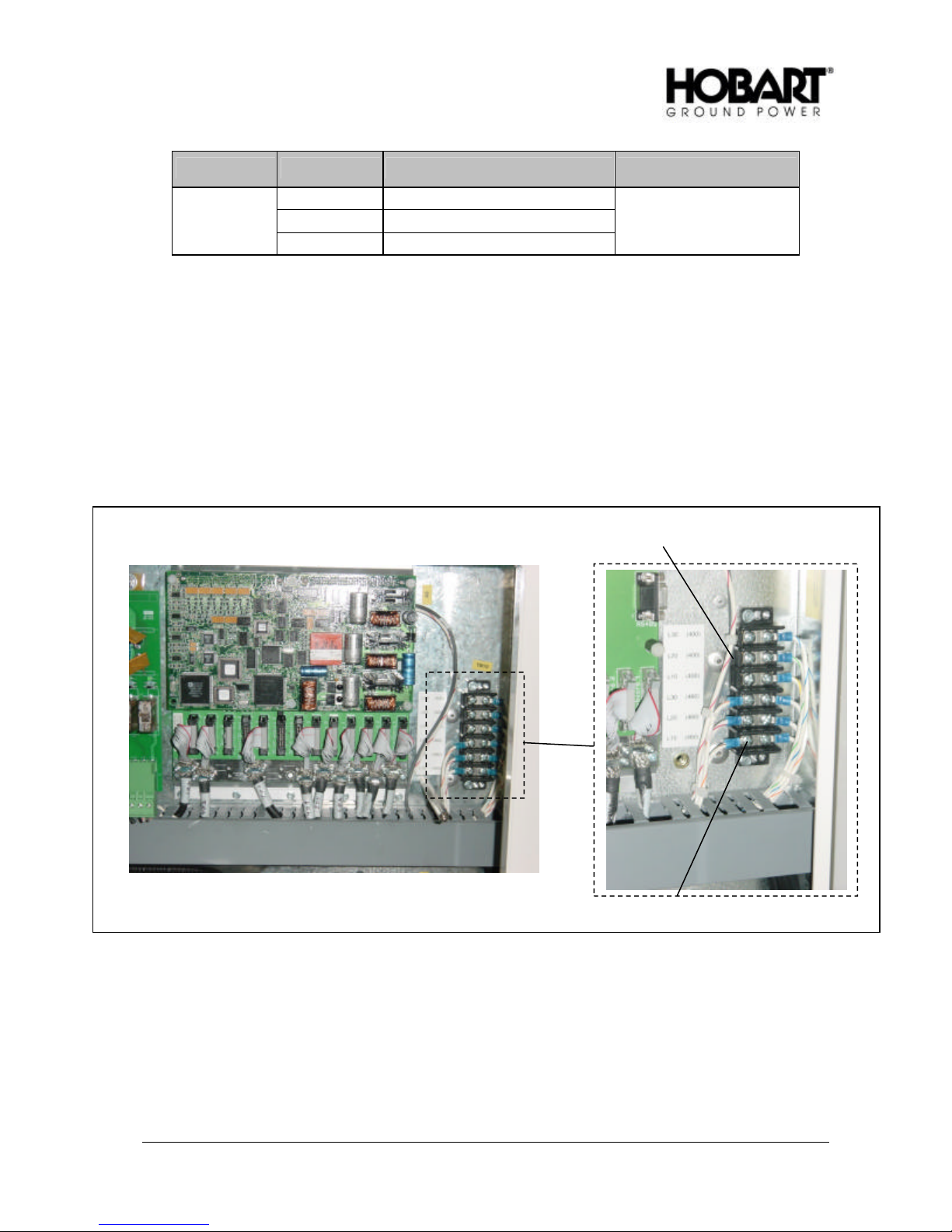
The internal converter circuitry operates at 400 VAC, so when setting the converter up to run on one
of the voltage settings in Figure 2, please make the proper connections are made on the terminal
strip in Figure 3.
100 A
400 V Input
b) Output
The supply cables to the aircraft , or to an eventual distribution box, are connected to the terminals
labeled A, B, C and N on the output contactor (Q2). All connection diagrams can be found in
Chapter 5.
January 18, 2007
Revision 2
460/480 V Input
Input Voltage Connecti ons
Figure 3
Chapter 1-3
Page 2
OM-2155 / Operation and Maintenance Manual
60 kVA PoWerMaster EV / Series 500381 / Solid State Converter
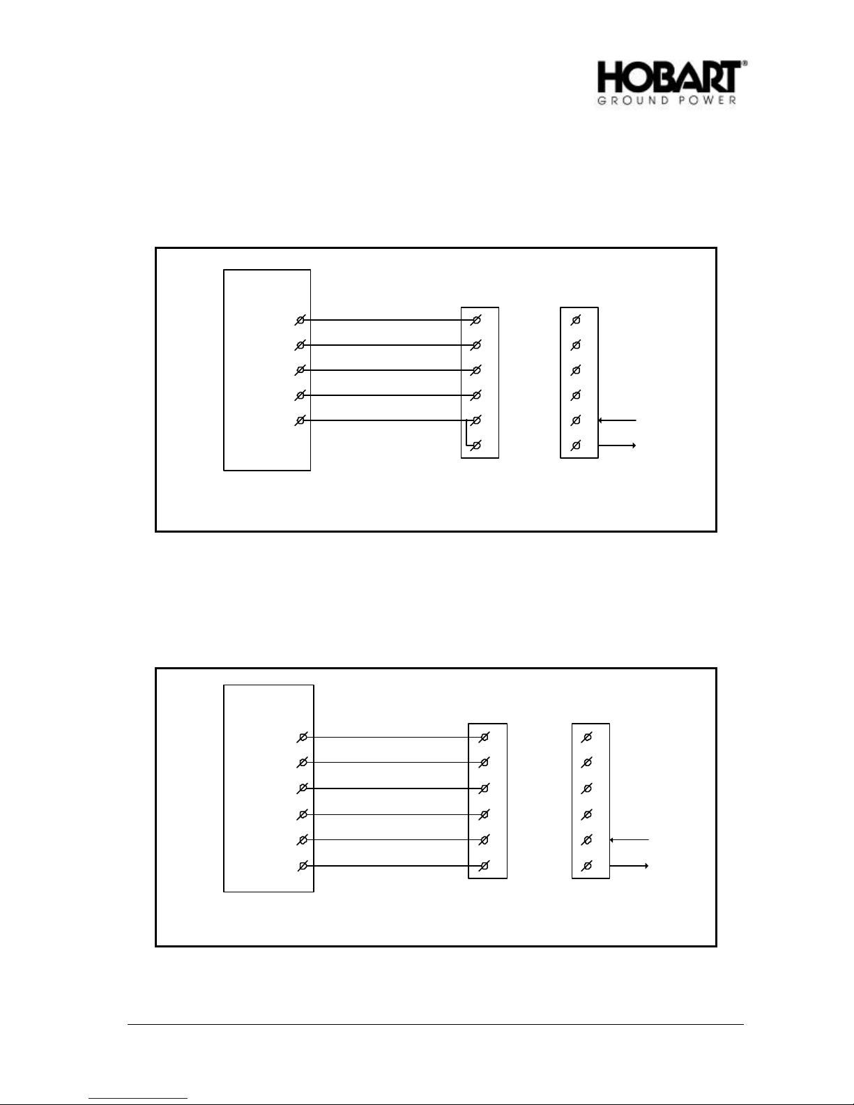
c) Interlock Safety System
To secure personnel’s health and safety, the converter is equipped with an interlock system. The
system ensures that the output contactor only stays energized as long as the plug is inserted in the
aircraft receptacle (i.e. as long as the aircraft provides 28 VDC with respect to 400 Hz neutral to
terminal F ). Standard wiring between converter and plug is shown in Figure 4.
A
B
C
N
F
Jumper
Ground Power Unit Cable Plug
A
B
C
N
F
E
A
B
C
N
+28VDC
F
To control
E
Aircraft Receptacle
Standard wiring diagram, Civil aircraft
Figure 4
When used in connection with some military aircraft, the converter normally has to provide 28 VDC
with respect to 400 Hz neutral to ensure a proper interlock function. Standard wiring between
converter and plug is shown in Figure 5.
Ground Power Unit Cable Plug
January 18, 2007
Revision 2
A
B
C
N
F
E+28VDC
A
B
C
N
F
E
Standard wiring diagram, Military aircraft
Figure 5
A
B
C
N
+28VDC
F
To control
E
Aircraft Receptacle
Chapter 1-3
Page 3

OM-2155 / Operation and Maintenance Manual
60 kVA PoWerMaster EV / Series 500381 / Solid State Converter
For service, maintenance and test purposes, the interlock system can be by -passed via the display
and keyboard set -up. To secure personnel’s health and safety, the unit automatically returns into
normal mode once it receives 28 VDC at terminal F. (i.e. when the converter is connected to an
aircraft).
d) Remote Control
The converter can be operated by means of the remote control terminals, which are label ed in
accordance with the diagrams found in Chapter 5. In case of very long remote control cables, it
might be necessary to use shielded cables. The shield has to be connected at both ends.
5) Setup of Parameters
It is possible to set and to adjust the following parameters by means of the converter's display and
keyboard. The proc edure is described in Chapter 3, Section 4.
a) Language
The display ed text is provided in 3 languages as a standard. It is possible to switch between the
languages by means of the dip switch (S1) situated on the back of the display. The table shows how
to select language.
Language/Position S1 - 1 S1 - 2 S1 - 3 S1 - 4
English OFF OFF X X
English ON ON X X
Spanish OFF ON X X
French ON OFF X X
X = position is random
b) Output Voltage Phase-Neutral
At delivery, the converter is set to nominal output voltage. This level can be adjusted, if re quired (i.e.
due to voltage drop in the supply cable ). The adjustment range is nominal voltage of ± 15%.
PLEASE NOTICE! If the voltage level falls outside the converter's operation range under
adjustment, the converter disengages and reports an under or over -voltage fault. The nominal
voltage as well as the levels for under and over -voltage are shown in Chapter 1, Section 2.
c) Output Voltage Compensation
If long output cables are used, the voltage drop becomes considerable during load situations.
However, it is possible to increase the converter's output voltage proportionate to the load current.
The adjustment is made while the converter is loaded and when the output cables have been
mounted. With a load current above 20% of the nominal output current, the voltage at the output plug
is adjusted to the required value (larger load current gives a better result). At delivery, the
compensation is pre -set to 0. The maximum compensation is 9V.
If only one outlet is available, only set up 1 is in use.
If two outlets are available , each output has its own set up (1 and 2). In case both outlets are in
use at the same time, the compensation will be set to half of the mean value of the two set up values.
January 18, 2007
Revision 2
Chapter 1-3
Page 4

OM-2155 / Operation and Maintenance Manual
60 kVA PoWerMaster EV / Series 500381 / Solid State Converter
d) Delay from Contactor OFF to Standby
If the converter's output contactor(s) is (are) not energized, the converter automatically passes into
standby mode after elapse of a pre -set period of time. This time delay can be set to values between
1 and 900 seconds. At delivery, the time delay is set to 15 seconds.
e) Date and Hour
The converter has a built-in real time clock showing the date and the hour. At delivery, the clock is
set to actual hour (USA EST time). The clock does not adjust itself at changes from summer time to
winter time and vice versa (no daylight savings time adjustment). It is possible to set year, month,
day, hour, minutes and seconds.
f) Setup of Interlock By-pass
The interlock safety system can be by -passed by setting the value to 1. For further information of the
interlock system, kindly refer to paragraph 4 in this chapter.
g) Setup of Fan By-pass
From the factory the by-pass value is set to 0, which means that the fan is temperature controlled. In
order to by -pass the temperature control, for instance for test purposes, the by-pass value is set to 1.
This means that the fan will run continuously.
h) Setup of Serial Protocol
There are two protocols available. If the value is set to 1, the Siemens 3964R protocol is chosen. If
the value is set to 2, the JBUS protocol is chosen. For further information about the protocols please
contact HOBART.
i) Setup of Serial Port
It is possible to select an RS232 port and an RS422/485 port. If the value is set to 1, the RS232 port
is selected. With the value set to 2, the RS422/485 protocol is selected.
j) Setup of JBUS Slave Address
If the JBUS protocol is selected, the slave address can be set up. The slave address can be set to
values between 1 and 247. At delivery, the address is set to 1.
k) Setup of Error Log, Power Log, Black Box
From the factory the by-pass value is set to 0. If for some reason it is necessary to clear the memory
log after installation the by -pass value is set to 1. After the reset, the by-pass value is automatically
set to 0.
l) Setup of Counters
The hour counter and the energy counter are reset, when the value is set to 1 (used to clear the
counter memory after installation). The value is automatically set to 0 after reset.
January 18, 2007
Revision 2
Chapter 1-3
Page 5

OM-2155 / Operation and Maintenance Manual
60 kVA PoWerMaster EV / Series 500381 / Solid State Converter
6) Maintenance
At least once a year it is recommended to
1. Check air filters - Wash or change as appropriate.
Note: We recommend, however, checking the air filters once a month to ensure proper air flow in
harsh environments.
2. Check that all fans are running properly.
3. Check bolt/screw and wire connections.
4. Check vibration dampers.
5. Visual inspection of all components.
6. Visual inspection of PCB's - control unit / gate drive.
7. Control of the contactors' contact sets and coil.
8. Control of output voltage.
9. Check of external cables and plugs.
Especially for outside mounted models, we recommend to:
10. Check rubber seals around panels and doors .
Especially for mobile -converters:
11. Check trailer tires for wear and tear.
12. Check that air pressure.
Note: We rec ommend, however, checking the tire pressure on a more frequent basis.
Battery back -up:
Situated on the processor board, a lithium battery assures that set -up data etc. is not lost if input power is
removed. The expected life of the battery is approximately 10 years. However, a low battery voltage
does not affect the internal safety system of the GPU that monitors the output voltage, among other
things. Thus aircraft connected to the GPU is not exposed to any danger. To avoid loss of data we
recommend you to replace the battery after 8 to 9 years of us e.
January 18, 2007
Revision 2
Chapter 1-3
Page 6

OM-2155 / Operation and Maintenance Manual
60 kVA PoWerMaster EV / Series 500381 / Solid State Converter
Section 4 Instruction for Use
The converter is equipped with the following operational controls and indications:
• Input breaker On/Off
• Emergency stop
• Display and keyboard
• Control panel with
Ø Input voltage indication (Mains)
Ø Fault indication (Common Error)
Ø Start / Reset push-button and indication for each output contactor
Ø Stop push-button for each output contactor
Ø Push button for lamp test (in common with indication of input voltage)
1) Input Breaker
When activated it connects the converter to the input power. Upon energizing, the converter runs
through a check program which tests the converter's internal and external conditions. If no faults or
irregularities are detected, the converter passes into standby mode.
2) Emergency Stop
The converter can be immediately stopped by activation of the emergency stop.
PLEASE NOTICE! The emergency stop must be released, before it is possible to restart the converter.
3) Control Panel
START 1 /MAINS /
LAMP TEST RESET
RESET
START 2 /
June 7, 2007
Revision 3
COMMON
ERROR
STOP 2STOP 1
Control Panel
Figure 1
Chapter 1-4
Page 1

OM-2155 / Operation and Maintenance Manual
60 kVA PoWerMaster EV / Series 500381 / Solid State Converter
a) Mains/Lamp Test
The mains lamp is lit, as soon as the converter is connected to the input power, and the input breaker
is activated. A push-button for lamp test can be built in. If built in, the activation of the button lights
all workable buttons at the control panel and keeps them lit until the button is released.
b) Common Error
This lamp is lit in case of a fault in the converter. The converter passes into alarm mode, and the
fault is displayed (for further information see Chapter F. The lamp is lit as long as the fault has not
been corrected.
c) Start/Reset
(1) Converter in Standby Mode:
A push of the Start/Reset button resets the converter, which then performs an auto-test of
internal and external parameters. If the test program is performed without detection of any errors
the system will state it is ready for use. The corresponding output contactor can now be
energized and the converter automatically passes from standby into 400 Hz available mode. The
Start/Reset button is lit, when 400 Hz is available at the output. The output contactor is activated
for 1 second no matter whether the interlock signal is present or not. If the interlock signal is not
available, the converter passes into standby mode after the elapse of the time delay to standby.
Missing interlock signal is shown at the display.
(2) Converter in 400 Hz Available
The converter is in 400 Hz available when at least one of the output contactors is energized. A
push of Start/Reset engages the output contactor of the corresponding outlet and the button is lit,
indicating that the output contac tor is energized. The converter supplies 400 Hz at the output,
until the output contactor(s) is de-energized. If one (single output) or both (dual output) interlock
signals become unavailable, the converter passes into stand-by mode after the elapse of the time
delay to standby. Missing interlock signal is shown at the display.
d) Stop
A push of the stop button disengages the corresponding output contactor. At de-energizing of both
output contactors, the converter immediately passes into standby mode.
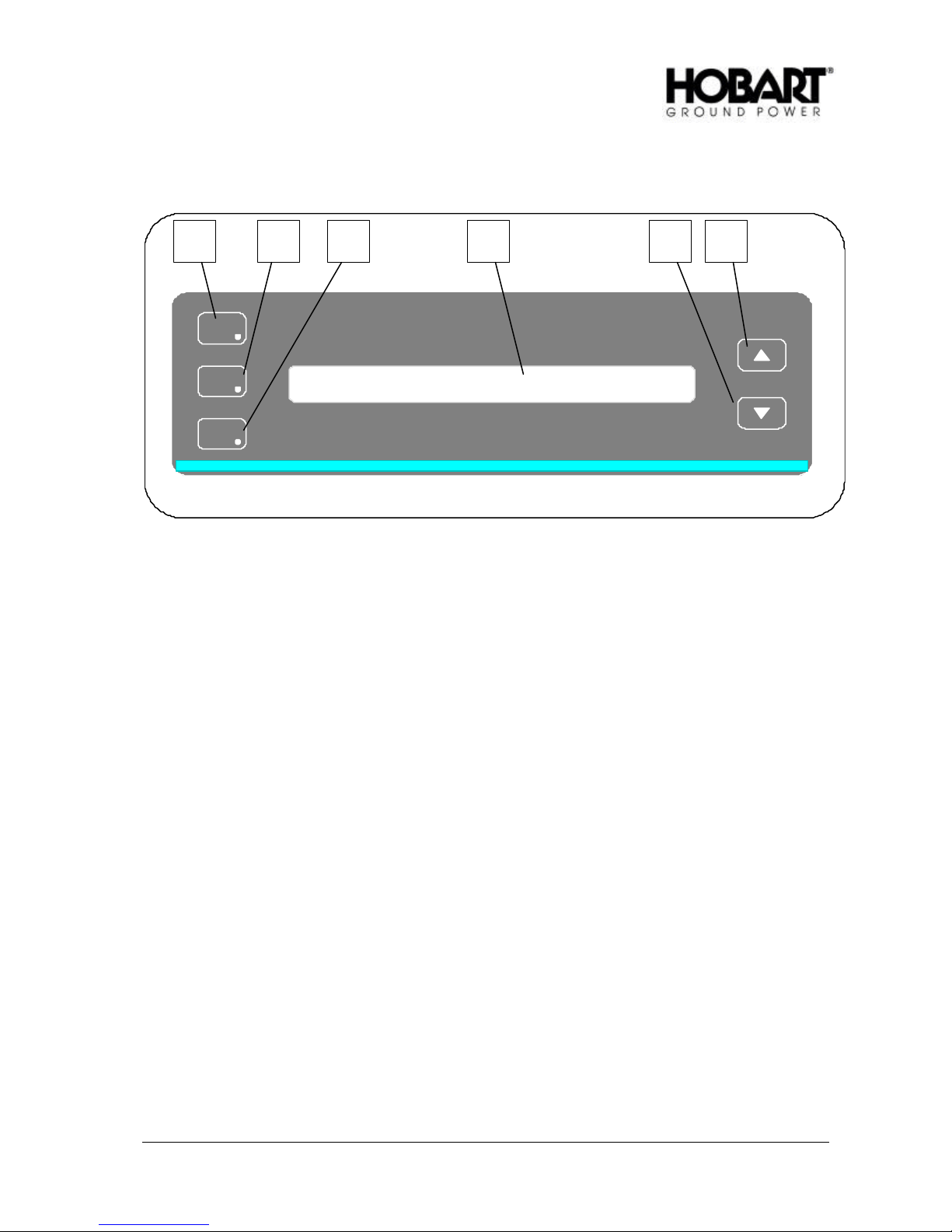
4) Display/Keyboard Interface
a) Basic Information
From the display/keyboard it is possible to:
1. view different internal and external parameters.
2. change GPU settings.
3. browse through the GPU memory.
4. adjust the display contrast.
June 7, 2007
Revision 3
Chapter 1-4
Page 2
OM-2155 / Operation and Maintenance Manual
NORMA
DISP
ALAR
DISP
SETU
GP
60 kVA PoWerMaster EV / Series 500381 / Solid State Converter
1 2 3 6 4 5
1. Display text area, 2 lines of 40 characters per line.
2. Key and LED : NORMAL DISP.
3. Key and LED : ALARM DISP.
4. Key and LED : SET-UP GPU.
5. Key : ARROW UP.
6. Key : ARROW DOWN.
b) How to Use Display/Keyboard
The display/keyboard reacts in 2 different ways on a key press.
(1) If switching between display modes or selecting a new picture, the display reacts on a key press
when the key is released. In these cases, the LED NORMAL DISP. flashes in order to show that
the key press is registered and that the display is working. The flashing stops when the desired
text appears on the display.
(2) If adjusting GPU-settings or display -contrast the value keeps changing, as long as one of the
ARROW keys is held down.
The keyboard is read 4 times per second. Therefore pressing a key must last longer than 1/4 of a
second to make sure that the key press is registered.
Display/Keyboard
Figure 2
June 7, 2007
Revision 3
Chapter 1-4
Page 3

OM-2155 / Operation and Maintenance Manual
60 kVA PoWerMaster EV / Series 500381 / Solid State Converter
c) Signification of the LED Signals
As already mentioned above, the LED NORMAL DISP flashes when the display has registered a key
press until the instruction has been carried out. Additionally, the LED's are lit as shown below:
Display mode: LED lit:
Default mode: NORMAL DISP.
View mode: NORMAL DISP.
Alarm mode: ALARM DISP.
Black box mode: ALARM DISP. & NORMAL DISP.
Power log mode: ALARM DISP. & SETUP GPU
Setup mode 1: SETUP GPU (constant light)
Setup mode 2: SETUP GPU (flashing light)
d) Parameter Updating
The time from a key press to the new picture shows, and the time between updating of the parameter
values, depend on the number of parameters in the picture. Normally this time will be less than 1
second. However, this is not applicable when adjusting setup parameters, where the update time is
very short.
e) Parameters Measuring Range
If the value of a parameter, in a selected display picture, is below the measuring range the display will
show the parameter as “< xxx”, where “xxx” shows the lowest value of the measuring range.
f) Adjusting Display Contrast (only LCD display)
If the light conditions or the viewer’s position makes it difficult to read the display, the display -contrast
can be adjusted by means of the NORMAL DISP. and ARROW UP/ ARROW DOWN keys. Contrast
adjusting can be made in any display mode.
Start by pressing NORMAL DISP and keep it down. Press ARROW UP or ARROW DOWN until the
display contrast is satisfactory. Release NORMAL DISP. key as the last. If not, the display changes
according to last pressed ARROW key.
g) Display Modes
There are 6 basic display modes:
• Default mode (display shows actual converter status)
• View mode (viewing parameters)
• Alarm mode (browsing through error log)
• Black box mode (browsing through errors and related parameters)
• Power log mode (browsing through logged operation information)
• Setup mode (viewing or changing settings)
The user can switch freely between the different display modes.
(1) Default Mode
Possibilities in Default mode:
In Default mode, the displayed picture is one of the following 5 pictures or an ALARM picture,
depending on the status of the converter.
June 7, 2007
Revision 3
Chapter 1-4
Page 4

OM-2155 / Operation and Maintenance Manual
60 kVA PoWerMaster EV / Series 500381 / Solid State Converter
STANDBY
SYSTEM READY FOR USE
year-mo-da ho.mi
OR
SYSTEM IN OPERATION
xxx/xxx.x V
year-mo-da
xxx A
OR
INTERLOCK SIGNAL MISSING
VERIFY PLUG POSITION OR CHECK CABLING
OR
EMERGENCY STOP ACTIVATED
SYSTEM STOP
OR
CONTROL UNIT IS WORKING
PLEASE WAIT
OR
ALARM PICTURE, according to Alarm mode
In case of built-in options such as magnetic card readers or 90% switches integrated in the
plug, additional display default pictures may occur.
Switching to other modes from Default mode:
Switch to: By pressing key:
View mode NORMAL DISP. or ARROW UP or ARROW DOWN
Alarm mode ALARM DISP.
Black box mode ALARM DISP. and ARROW UP
Power log mode ALARM DISP. and ARROW DOWN
Setup mode SETUP GPU
Switching to Default mode from other modes :
Switch from: By pressing key:
View mode NORMAL DISP
Alarm mode NORMAL DISP. first key press gives View mode, the
second Default mode
Black box mode NORMAL DISP. first key press gives View mode, the
second Default mode
Power log mode NORMAL DISP. first key press gives View mode, the
second Default mode
Setup mode NORMAL DISP.
June 7, 2007
Revision 3
ho.mi
xxx.x Hz
Chapter 1-4
Page 5

OM-2155 / Operation and Maintenance Manual
60 kVA PoWerMaster EV / Series 500381 / Solid State Converter
(2) View Mode
Possibilities in View mode:
When from one of the other display modes View mode is selected, the first picture shown is:
INPUT VOLTAGE:PHASE-PHASE
L1-L2=xxx
L2-L3=xxx
By pressing and releasing ARROW UP or ARROW DOWN, the user can browse through the
following pictures, including the above shown picture.
ARROW UP : Order as shown below
ARROW DOWN: Reverse order of below
INPUT FREQUENCY
[Hz]
VOLTAGE AT DC CAPACITOR BANK
[V]
OUTPUT VOLTAGE:PHASE-NEUTRAL
A=xxx B=xxx
OUTPUT VOLTAGE:PHASE-PHASE
AB=xxx BC=xxx
CA=xxx
OUTPUT CURRENT
A=xxx B=xxx
INVERTER CURRENT
A=xxx B=xxx
ACTIVE OUTPUT POWER
A=xxx B=xxx
APPARENT OUTPUT POWER
A=xxx B=xxx
OUTPUT FREQUENCY
[Hz]
C=xxx
C=xxx
C=xxx
C=xxx
C=xxx
[V]
L3-L1=xxx
xxx.x
xxx
[V]
Avg=xxx.x
[V]
Avg=xxx
[A]
Avg=xxx.x
[A]
[kW]
S =xxx
[kVA]
S =xxx
xxx.x
June 7, 2007
Revision 3
Chapter 1-4
Page 6
 Loading...