

Hobart 60PL20 Operation And Maintenance Manual

OM-2053
032089
Revised 050693
Revised 050994
OPERATION AND MAINTENANCE MANUAL
with
ILLUSTRATED PARTS LIST
for
ENGINE-DRIVEN GENERATOR SET
SPECIFICATION NUMBER 7009 , 7009A, & 7009B
For Truck or Trailer Mounting
MODEL No. 60PL20
60-KVA, 400-HZ, 115/200-V AC, 3-PHASE
with
PERKINS DIESEL ENGINE
TYPE 6.3544
Hobart Brothers Company
Airport Systems Group
Ground Power Equipment
Troy, Ohio 45373
U.S.A.

This page intentionally left blank.

OM-2053
SAFETY INSTRUCTIONS AND WARNINGS FOR ELECTRICAL POWER EQUIPMENT
WARNING
ELECTRIC SHOCK can KILL. Do not touch live electrical parts.
ELECTRIC ARC FLASH can injure eyes, burn skin, cause equipment damage, and ignite combustible
material. DO NOT use power cables to break load and prevent tools from causing short circuits.
IMPROPER PHASE CONNECTION, PARALLELING, OR USE can damage this and attached
equipment.
Important:- Protect all operating personnel. Read, understand, and follow all instructions in
the Operating/Instruction Manual before installing, operating, or servicing the equipment. Keep
the manual available for future use by all operators.
A. GENERAL
Equipment that supplies electrical power can cause serious injury or death, or damage to other equipment
or property. The operator must strictly observe all safety rules and take precautionary actions. Safe practices
have been developed from past experience in the use of power source equipment. While certain practices below apply only to electrically-powered equipment, other practices apply to engine-driven equipment, and some
practices to both.
B. SHOCK PREVENTION
Bare conductors, or terminals in the output circuit, or ungrounded, electrically-live equipment can fatally
shock a person. Have a certified electrician verify that the equipment is adequately grounded and learn what
terminals and parts are electrically HOT. Avoid hot spots on machine. Use proper safety clothing, procedures,
and test equipment.
The electrical resistance of the body is decreased when wet, permitting dangerous currents to flow
through it. When inspecting or servicing equipment, do not work in damp areas. Stand on a dry rubber mat or
dry wood, use insulating gloves when dampness or sweat cannot be avoided. Keep clothing dry, and never
work alone
1. Installation and Grounding of Electrically Powered Equipment
Equipment driven by electric motors (rather than by diesel or gasoline engines) must be installed and
maintained in accordance with the National Electrical Code, ANSI/NFPA 70, or other applicable codes. A
power disconnect switch or circuit breaker must be located at the equipment. Check the nameplate for voltage, frequency, and phase requirements. If only 3-phase power is available, connect any single-phase rated
equipment to only two wires of the 3-phase line. DO NOT CONNECT the equipment grounding conductor
(lead) to the third live wire of the 3-phase line, as this makes the equipment frame electrically HOT, which can
cause a fatal shock.
Always connect the grounding lead, if supplied in a power line cable, to the grounded switch box or building ground. If not provided, use a separate grounding lead. Ensure that the current (amperage) capacity of
the grounding lead will be adequate for the worst fault current situation. Refer t o the National Electrical Code
ANSI/NFPA 70 for details. Do not remove plug ground prongs. Use correctly mating receptacles.
2. Output Cables and Terminals
Inspect cables frequently for damage to the insulation and the connectors. Replace or repair cracked or
worn cables immediately. Do not overload cables. Do not touch output terminal while equipment is energized.
3. Service and Maintenance
This equipment must be maintained in good electrical and mechanical condition to avoid hazards stemming from disrepair. Report any equipment defect or safety hazard to the supervisor and discontinue use of
the equipment until its safety has been assured. Repairs should be made by qualified personnel only.
Before inspecting or servicing electrically-powered equipment, take the following precautions:
a. Shut OFF all power at the disconnecting switch or line breaker before inspecting or servicing the
equipment.
b. Lock switch OPEN (or remove line fuses) so that power cannot be turned on accidentally.
December 31/91 Revised Page 1

OM-2053
c. Disconnect power to equipment if it is out of service.
d. If troubleshooting must be done with the unit energized, have another person present who is trained in
turning off the equipment and providing or calling for first aid.
C . FIRE AND EXPLOSION PREVENTION
Fire and explosion are caused by electrical short circuits, combustible material near engine exhaust pip-
ing, misuse of batteries and fuel, or unsafe operating or fueling conditions.
1. Electrical Short Circuits and Overloads
Overloaded or shorted equipment can become hot enough to cause fires by self destruction or by causing
nearby combustibles to ignite. For electrically-powered equipment, provide primary input protection to remove
short circuited or heavily overloaded equipment from the line.
2. Batteries
Batteries may explode and/or give off flammable hydrogen gas. Acid and arcing from a ruptured battery
can cause fires and additional failures. When servicing,do not smoke, cause sparking, or use open flame
near the battery.
3. Engine Fuel
Use only approved fuel container or fueling system. Fires and explosions can occur if the fuel tank is not
grounded prior to or during fuel transfer. Shut unit DOWN before removing fuel tank cap. DO NOT completely fill tank, because heat from the equipment may cause fuel expansion overflow. Remove all spilled fuel
IMMEDIATELY, including any that penetrates the unit. After clean-up, open equipment doors and blow fumes
away with compressed air.
D. TOXIC FUME PREVENTION
Carbon monoxide - Engine exhaust fumes can kill and cause health problems. Pipe or vent the exhaust
fumes to a suitable exhaust duct or outdoors. Never locate engine exhausts near intake ducts of air conditioners.
E. BODILY INJURY PREVENTION
Serious injury can result from contact with fans inside some equipment. Shut DOWN such equipmentfor
inspection and routine maintenance. When equipment is in operation, use extreme care in doing necessary
trouble-shooting and adjustment. Do not remove guards while equipment is operating.
F. MEDICAL AND FIRST AID TREATMENT
First aid facilities and a qualified first aid person should be available for each shift for immediate treat-
ment of all injury victims. Electric shock victims should be checked by a physician and taken to a hospital immediately if any abnormal signs are observed.
EMERGENCY FIRST AID
Call physician immediately. Seek additional assistance. Use First Aid techniques recommended
by American Red Cross until medical help arrives.
IF BREATHING IS DIFFICULT, give oxygen, if available, and have victim lie down. FOR ELECTRICAL SHOCK, turn off power. Remove victim; if not breathing, begin artificial respiration, preferably mouth-to-mouth. If no detectable pulse, begin external heart massage. CALL EMERGENCY
RESCUE SQUAD IMMEDIATELY.
G. EQUIPMENT PRECAUTIONARY LABELS
Inspect all precautionary labels on the equipment monthly. Order and inspect all labels that cannot be
easily read.
Page 2 December 31/91 Revised

OM-2053
INTRODUCTION
This manual contains operation and maintenance information for a 400-Hertz generator set manufactured
by Hobart Brothers Company, Power Systems Group, Troy, Ohio 45373.
This manual is not intended to be a textbook on electricity or electronics. Its primary purpose is to provide
information and instructions to experienced operators, electricians, and mechanics who h ave never seen
or operated this equipment. It is the intent of this manual to guide and assist operators and maintenance
people in the proper use and care of the equipment.
Use of the manual should not be put off until a trouble or need for help develops. Read the instructions be-
fore starting the unit. Learn to use the manual and to locate information contained in it. Its style and ar-
rangement are very similar to commercial aircraft manuals. The manual is divided into six chapters. Each
chapter is divided into as many sections as required. Each new section starts with page 1. Each page is
identified by chapter, section and page number, which are located in the lower, outside corner. When infor-
mation located in another portion of the manual is referred to, its location is identified by a chapter, sec-
tion, and paragraph, or figure number.
For example, “
Chapter and Section are not indicated in a reference, the referenced material is located in the same sec-
tion as the reference, Example,
In addition to operation and maintenance instructions, the manual contains an illustrated parts list in Chap-
ter 4, and a collection of manufacturer’s literature and supplemental information in Chapter 6.
Content of the manual is arranged as follows:
Chapter 1. Description/Operation
Chapter 2. Servicing
Chapter 3. Troubleshooting
Chapter 4. Illustrated Parts List
Chapter 5. Optional Equipment
Chapter 6. Manufacturer’s Literature
(See 2-3, Para. B)
” refers to information located in Chapter 2, Section 3, Paragraph B. If a
(See Para. B).
December 31/91 Revised Introduction
Page 1

OM-2053
This page intentionally left blank.
Introduction December 31/91 Revised
Page 2

LIST OF EFFECTIVE PAGES
CHAPTER/ CHAPTER/
SECTION PAGE DATE SECTION PAGE DATE
List of 1 Mar 20/89 1-3 1 Mar 20/89
Effective 2 Mar 20/89 1-3 2 Mar 20/89
Pages 1-3 3 Mar 20/89
1-3 4 Mar 20/89
Introduction 1 Mar 20/89 1-3 5 Mar 20/89
Introduction 2 Mar 20/89 1-3 6 Mar 20/89
Contents 1 Mar 20/89 2-1 1 Mar 20/89
Contents 2 Mar 20/89 2-1 2 Mar 20/89
Contents 3 Mar 20/89 2-1 3 Mar 20/89
Contents 4 Mar 20/89 2-1 4 Mar 20/89
Contents 5 Mar 20/89 2-1 5 Mar 20/89
Contents 6 Mar 20/89 2-1 6 Mar 20/89
Contents 7 Mar 20/89 2-1 7 Mar 20/89
Contents 8 Mar 20/89 2-1 8 Mar 20/89
Contents 9 Mar 20/89 2-1 9 Mar 20/89
Contents 10 Mar 20/89 2-1 10 Mar 20/89
Contents 11 Mar 20/89 2-1 11 Mar 20/89
Contents 12 Mar 20/89 2-1 12 Mar 20/89
2-1 13 Mar 20/89
1-1 1 Mar 20/89 2-1 14 Mar 20/89
1-1 2 Mar 20/89
1-1 3 Mar 20/89 2-2 1 Mar 20/89
1-1 4 Mar 20/89 2-2 2 Mar 20/89
1-1 5 Mar 20/89 2-2 3 Mar 20/89
1-1 6 Mar 20/89 2-2 4 Mar 20/89
1-1 7 Mar 20/89 2-2 5 Mar 20/89
1-1 8 Mar 20/89 2-2 6 Mar 20/89
1-1 9 Mar 20/89
1-1 10 Mar 20/89 2-3 1 Mar 20/89
1-1 11 Mar 20/89 2-3 2 Mar 20/89
1-1 12 Mar 20/89 2-3 3 Mar 20/89
1-1 13 Mar 20/89 2-3 4 Mar 20/89
1-1 14 Mar 20/89 2-3 5 Mar 20/89
1-1 15 Mar 20/89 2-3 6 Mar 20/89
1-1 16 Mar 20/89 2-3 7 Mar 20/89
1-1 17 Mar 20/89 2-3 8 Mar 20/89
1-1 18 Mar 20/89 2-3 9 Mar 20/89
1-1 19 Mar 20/89 2-3 10 Mar 20/89
1-1 20 Mar 20/89 2-3 11 Mar 20/89
1-1 21 Mar 20/89 2-3 12 Mar 20/89
1-1 22 Mar 20/89 2-3 13 Mar 20/89
2-3 14 Mar 20/89
1-2 1 Mar 20/89 2-3 15 Mar 20/89
1-2 2 Mar 20/89 2-3 16 Mar 20/89
1-2 3 Mar 20/89 2-3 17 Mar 20/89
1-2 4 Mar 20/89 2-3 18 Mar 20/89
OM-2053
March 20/89 List of Effective Pages
Page 1

OM-2053
LIST OF EFFECTIVE PAGES
CHAPTER/ CHAPTER/
SECTION PAGE DATE SECTION PAGE DATE
3-1 1 Mar 20/89 4-3 6 Mar 20/89
3-1 2 Mar 20/89 4-3 7 Mar 20/89
3-1 3 Mar 20/89 4-3 8 Mar 20/89
3-1 4 Mar 20/89 4-3 9 Mar 20/89
3-1 5 Mar 20/89 4-3 10 Mar 20/89
3-1 6 Mar 20/89 4-3 11 Mar 20/89
3-1 7 Mar 20/89 4-3 12 Mar 20/89
3-1 8 Mar 20/89 4-3 13 Mar 20/89
3-1 9 Mar 20/89 4-3 14 Mar 20/89
3-1 10 Mar 20/89 4-3 15 Mar 20/89
3-1 11 Mar 20/89 4-3 16 Mar 20/89
3-1 12 Mar 20/89 4-3 17 Mar 20/89
3-1 13 Mar 20/89 4-3 18 Mar 20/89
3-1 14 Mar 20/89 4-3 19 Mar 20/89
3-1 15 Mar 20/89 4-3 20 Mar 20/89
3-1 16 Mar 20/89 4-3 21 Mar 20/89
3-1 17 Mar 20/89 4-3 22 Mar 20/89
3-1 18 Mar 20/89 4-3 23 Mar 20/89
3-1 19 Mar 20/89 4-3 24 Mar 20/89
3-1 20 Mar 20/89 4-3 25 Mar 20/89
3-1 21 Mar 20/89 4-3 26 Mar 20/89
3-1 22 Mar 20/89 4-3 27 Mar 20/89
3-1 23 Mar 20/89 4-3 28 Mar 20/89
3-1 24 Mar 20/89 4-3 29 Mar 20/89
4-3 30 Mar 20/89
4-1 1 Mar 20/89 4-3 31 Mar 20/89
4-1 2 Mar 20/89 4-3 32 Mar 20/89
4-3 33 Mar 20/89
4-2 1 Mar 20/89 4-3 34 Mar 20/89
4-2 2 Mar 20/89
4-2 3 Mar 20/89 4-4 1 Mar 20/89
4-2 4 Mar 20/89 4-4 2 Mar 20/89
4-2 5 Mar 20/89 4-4 3 Mar 20/89
4-2 6 Mar 20/89 4-4 4 Mar 20/89
4-2 7 Mar 20/89 4-4 5 Mar 20/89
4-2 8 Mar 20/89 4-4 6 Mar 20/89
4-3 1 Mar 20/89 5-0 1 Mar 20/89
4-3 2 Mar 20/89 5-0 2 Mar 20/89
4-3 3 Mar 20/89
4-3 4 Mar 20/89 6-0 1 Mar 20/89
4-3 5 Mar 20/89 6-0 2 Mar 20/89
List of Effective Pages March 20/89
Page 2

OM-2053
Table of Contents
SUBJECT CHAPTER/SECTION PAGE
WARNING
INTRODUCTION
Chapter 1. Description/Operation
Section 1. Description 1-1 1
1. General 1-1 1
2. Orientation 1-1 1
3. Special Features 1-1 1
A. Protective Monitor 1-1 1
B. Voltage Regulator 1-1 1
C. Electric Governor 1-1 1
4. Canopy 1-1 4
5. Optional Equipment 1-1 4
6. Engine, Generator, and Controls Assembly 1-1 4
A. Basic Engine 1-1 4
B. Engine Manufacturer’s Equipment 1-1 4
C.Hobart Engine Equipment 1-1 6
(1) Electric governor system 1-1 6
(a) Magnetic pickup 1-1 6
(b) Control unit 1-1 6
(c) Actuator 1-1 6
(2) Engine electrical system 1-1 6
(3) Engine protective devices 1-1 6
(a) High coolant temperature switch 1-1 6
(b) Oil pressure switch 1-1 6
(4) Air cleaner 1-1 7
(5) Exhaust system 1-1 7
(6) Radiator 1-1 7
D. Generator 1-1 8
E. Control Box Assembly 1-1 9
(1) Front Panel 1-1 9
(a) Generator output monitors (meters) 1-1 9
(b) Meter and line switches 1 -1 9
(c) Instrument light 1-1 9
(d) Indicating lights 1-1 9
(2) Control box internal components 1-1 9
(a) Sensing modules 1-1 10
(b) Memory and time delay module 1-1 11
(c) Excitation-deenergization relay 1-1 11
(d) Plug-interlock relay 1-1 11
(e) Test-bank switch 1-1 11
(f) Resistor 1-1 11
(g) Fuse-interlock relay 1-1 12
(h) Auxiliary underfrequency relay 1-1 12
(j ) Terminal boards 1-1 12
December 31/91 Revised Table of Contents
Page 1

OM-2053
Table of Contents
SUBJECT CHAPTER/SECTION PAGE
(k) Solid-state voltage regulator 1-1 12
(l) Overload module 1-1 12
(m) Rectifier 1-1 12
F. Engine Control Panel 1-1 12
(1) Engine instruments 1-1 12
(a) Ammeter 1-1 12
(b) Temperature gage 1-1 12
(c) Oil pressure gage and oil
pressure switch 1-1 14
(d) Hourmeter 1-1 14
(e) Fuel gage and blocking diodes 1-1 14
(2) Engine and generator controls 1-1 14
(a) Engine-generator control switch 1-1 14
(b) Contactor control switch 1-1 14
(c) Instrument light and switch 1-1 14
(d) Engine starting circuit 1-1 15
(e) Indicating lights 1-1 15
(f) Fuse 1-1 15
G. Load Contactor Circuit Components 1-1 15
(1) Load contactor 1-1 15
(2) Current transformers 1-1 15
(a) Ammeter current transformers 1-1 15
(b) Line-drop current transformers 1-1 15
(c) Overload current transformers 1-1 15
(3) Overload module 1-1 17
(4) Rectifier 1-1 17
Section 2. Preparation For Use,
Storage, Or Shipping 1-2 1
1. Preparation for Use 1-2 1
A. Inspection/Check 1-2 1
B. Installing Three-phase AC Output Cables 1-2 1
2. Preparation for Storage 1-2 2
A. General 1-2 2
B. Temporary Storage 1-2 2
C. Long Time Storage 1-2 2
Section 3. Operation 1-3 1
1. General 1-3 1
2. Operating the Generator Set 1-3 1
A. Pre-start Inspection 1-3 1
B. Normal Engine Starting Procedures 1-3 1
C.Preparation for Power Delivery 1-3 3
D. Power Delivery 1-3 4
E. Discontinue Power Delivery 1-3 4
F. Stopping the Engine 1-3 4
Table of Contents December 31/91 Revised
Page 2

OM-2053
Table of Contents
SUBJECT CHAPTER/SECTION PAGE
3. Trailer Operation 1-3 5
A. Towing 1-3 5
B. Parking 1-3 5
Chapter 2. Service
Section 1. Maintenance 2-1 1
1. General 2-1 1
2. Inspection 2-1 1
3. Lubrication 2-1 1
A. General 2-1 1
B. Generator 2-1 1
C. Generator Controls 2-1 1
D. Engine 2-1 1
(1) Lubrication schedule 2-1 2
(2) Oil specification 2-1 2
(3) Oil viscosity 2-1 2
(4) Changing engine oil 2-1 2
(5) Changing engine oil filter 2-1 2
E. Starter 2-1 2
F. Trailer 2-1 2
(1) Front axle assembly 2-1 2
(2) Wheel bearings 2-1 3
4. Air Cleaner Service 2-1 3
A. Inspecting the Air Cleaner 2-1 3
B. Cleaning Instructions 2-1 4
C. Disposal 2-1 4
5. Engine Fuel 2-1 4
A. Quality 2-1 4
B. Fuel Filter 2-1 4
6. Engine Cooling System 2-1 4
A. General 2-1 4
B. Radiator Cap 2-1 5
(1) General 2-1 5
(2) Removal 2-1 5
(3) Installation 2-1 5
C. Warm Weather Operation 2-1 5
D. Cold Weather Operation 2-1 5
(1) General 2-1 5
(2) Checking coolant solution 2-1 5
(3) Preparing the coolant solution 2-1 5
(4) Installing the antifreeze solution 2-1 6
E. Draining the Cooling System 2-1 6
F. Cleaning the Cooling System 2-1 6
G. Cleaning the Radiator Core 2-1 7
H. Filling the Cooling System 2-1 7
December 31/91 Revised Table of Contents
Page 3

OM-2053
Table of Contents
SUBJECT CHAPTER/SECTION PAGE
7. Generator Maintenance 2-1 7
A. Cleaning 2-1 7
B. Adjustment 2-1 7
8. Drive Belts 2-1 8
A. Checking Belt Tension 2-1 8
B. Belt Adjustment 2-1 8
9. Battery Maintenance 2-1 8
A. General 2-1 8
B. Battery Location and Accessibility 2-1 8
C. Battery Care 2-1 8
D. Liquid Level 2-1 9
E. Cleaning the Battery 2-1 9
F.Testing the Battery 2-1 9
(1) Test with Battery-Starter Tester 2-1 9
(2) Test with Hydrometer 2-1 9
10. Service Helps 2-1 10
A. Wiring 2-1 10
B. Generator Exciter 2-1 10
(1) Preparation for exciter removal. 2-1 10
(2) Exciter removal 2-1 10
(3) Exciter installation 2-1 10
Section 2. Inspection/Check 2-2 1
1. General 2-21 1
2. Engine 2-2 1
A. Fuel 2-2 1
B. Lubrication 2-2 1
C. Coolant 2-2 1
D. V-Belt 2-2 1
E. Exhaust System 2-2 1
3. Electrical System (12-V DC) 2-2 2
A. Lights 2-2 2
B. Fuses 2-2 2
C. Wiring and Connections 2-2 3
4. Electrical System (115-V AC) 2-2 4
A. Monitoring Instruments 2-2 4
B. Indicating Lights 2-2 4
C. Protective Modules 2-2 4
D. Wiring and Connections 2-2 4
5. Trailer 2-2 4
Table of Contents December 31/91 Revised
Page 4

OM-2053
Table of Contents
SUBJECT CHAPTER/SECTION PAGE
Section 3. Adjustment/Test 2-3 1
1. General 2-3 1
2. Generator Set Test 2-3 1
A. Pre-operational Test Procedures 2-3 1
B. Operational Test Procedures 2-3 1
3. Generator Set Adjustment 2-3 7
A. Generator Adjustment 2-3 7
B. Voltage Regulator Adjustments 2-3 7
C.Basic Engine Adjustments 2-3 7
D. Engine Accessories Adjustment 2-3 8
(1) Generator and fan belt adjustment 2-3 8
E. Electric Governor System Adjustment
(Woodward Governor Kit) 2-3 8
(1) General 2-3 8
(2) Actuator linkage adjustment 2-3 9
(3) Magnetic pickup adjustment 2-3 10
(4) Governor Control Unit Adjustment 2-3 11
F. Electric Governor System Adjustment
(Barber-Colman Governor Kit) 2-3 13
(1) General 2-3 13
(2) Actuator Linkage Adjustment 2-3 13
(3) Magnetic Pick-up Inspection / Adjustment 2-3 15
(4) Governor Controller Adjustment 2-3 16
(5) Re-checking Actuator Linkage 2-3 16
(6) Checking the Actuator 2-3 16
(7) Troubleshooting 2-3 18
4. Generator and Exciter Test 2-3 19
5. Diode Test 2-3 19
Chapter 3.Troubleshooting
Section 1. Trouble Shooting
Procedures 3-1 1
1. General 3-1 1
2. Troubleshooting Chart 3-1 1
A. Description 3-1 1
B. Use of the Trouble Shooting Chart 3-1 1
3. Equipment for Troubleshooting 3-1 2
4. Safety - WARNING: 3-1 2
5. Parts Replacement 3-1 2
6. Test Values 3-1 2
7. Checking Connections and Leads 3-1 3
8. Electric Governor Trouble Shooting 3-1 3
9. Engine Trouble Shooting Procedures 3-1 3
10.Illustrations 3-1 3
December 31/91 Revised Table of Contents
Page 5

OM-2053
Table of Contents
SUBJECT CHAPTER/SECTION PAGE
Chapter 4. Illustrated Parts List
Section 1. Introduction 4-1 1
1. General 4-1 1
2. Purpose 4-1 1
3. Arrangement 4-1 1
4. Explanation of Parts List 4-1 1
A. Contents 4-1 1
B. Parts List Form 4-1 2
(1) FIGURE-ITEM NO. Column 4-1 2
(2) HOBART PART NUMBER Column 4-1 2
(3) NOMENCLATURE Column 4-1 2
(4) REC. SPARES Column 4-1 2
(5) “EFF” (Effective) Column 4-1 2
(6) UNITS PER ASSEMBLY Column 4-1 2
Section 2. Manufacturer’s Codes 4-2 1
1. Explanation of Manufacturer’s
(Vendor) Code List 4-2 1
Section 3. Parts List 4-3 1
1. Explanation of Parts List Arrangement 4-3 1
2. Symbols and Abbreviations 4-3 1
Section 4. Numerical Index 4-4 1
1. Explanation of Numerical Index 4-4 1
Chapter 5. Optional Equipment
Chapter 6. Manufacturers Literature
Table of Contents December 31/91 Revised
Page 6

OM-2053
CHAPTER 1. DESCRIPTION/OPERATION
SECTION 1. DESCRIPTION
1. General
This manual covers two trailer-mounted 60-kVA generator sets manufactured by Hobart Brothers Company and identified respectively as Specification No. 7009-1, Specification No. 7009A-1, and Specification No. 7009B-1
All three generator sets feature an armature with Hoover Bearings, Browning Coupler, and different magnetic pole construction for the generator revolving field. This new armature can be easily identified by two
copper rings on each end of the field coils and copper wedges between magnetic poles.
The difference between Specification No. 7009-1and Specification No. 7009A-1 is that Specification No.
7009A-1 features new-style doors on the canopy assembly. Specification 7009B-1 is physically and electrically identical toSpecification 7009A-1, except that a Barber-Colman engine speed governor is used instead of the Woodward governor used on Specification No. 7009-1and Specification No. 7009A-1.
The purpose of these generator sets
to a parked
ators are not running. See Figure 2 for specifications and capabilities.
(or towed)
aircraft for operation of the aircraft’s electrical equipment when the on-board gener-
(Fig. 1)
is to generate and deliver regulated, 400-Hz electrical power
2. Orientation
For purpose of orientation and to familiarize operators and maintenance personnel with the location of
components, the radiator is considered to be at the FRONT of the unit. The generator and controls are at
the REAR. RIGHT and LEFT are determined by standing at the rear end facing the machine.
3. Special Features
These generator sets have many special features which are later described more fully under the assemblies in which they appear. Some of the main features are mentioned here and described briefly.
A. Protective Monitor
A single, solid-state device
ator output circuit and functions to cause the load to be disconnected from the generator if an abnormal condition of voltage, frequency, or load develops.
B. Voltage Regulator
A solid-state, adjustable voltage regulator
tion at the aircraft
of output cable sizes and lengths.
(or distribution panel when applicable).
(7, Fig. 7)
receives signals from all of the fault sensing units in the gener-
(Items 13 and 17, Fig. 7)
The regulator is also adjustable for a variety
provides automatic voltage regula-
C. Electric Governor
The engine is equipped with an all electric type governor kit
equipment more fully described under the engine description.
December 31/91 Revised 1-1
(13 and 16, Fig. 3)
and other special
Page 1
OM-2053
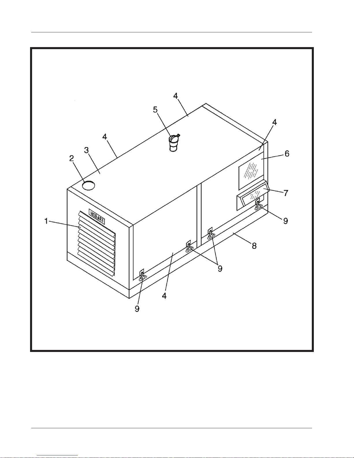
1. Engine fan exhaust deflectors 6. Generator control panel window
2. Radiator cap access hole 7. Engine control panel window
3. Canopy 8. Mounting frame
4. Doors (attached to canopy) 9. Doorlatches
5. Engine exhaust pipe and cover
1-1 December 31/91 Revised
Page 2
Generator Set
Figure 1

PHYSICAL
BASIC GENERATOR SET
Length overall 84 inches (2134 mm)
Width 33 inches (838 mm)
Height 43 inches (1092 mm)
Weight (Approximate) 3655 pounds (1658 kg)
TRAILER-MOUNTED GENERATOR SET
Length overall 90 inches (2286 mm)
Width 66 inches (1676 mm)
Height 57 inches (1448 mm)
Weight (Approximate) 4120 pounds (1868.5 kg)
GENERATOR
Output power rating 60 KVA
Output voltage 115/200 V
Rated load capacity 173 A
Frequency (cycles-per-second) 400 Hz
Output kilowatts 48 KW
Power factor 0.8 PF
Duty cycle 100%
Operating speed at 400 Hz 2000 RPM
Overload capacity (125% of rated load capacity) 216 A
OM-2053
GENERATOR PROTECTIVE SYSTEM
Overvoltage relay trips 130 V to 134 V; resets 125 V
Undervoltage relay trips 102 V or below; resets 110 V
Overfrequency relay trips 415 Hz to 425 Hz; resets 410 Hz
Underfrequency relay trips 375 Hz to 385 Hz; resets 385 Hz
Overload relay trips 112 KVA in less than 5 minutes
Undervoltage time delay relay 4 to 12 seconds
ENGINE
Manufacturer Perkins Diesel
Model 6.3544
Type In-line, 6-cylinder, 4-cycle Diesel
Displacement 354 cu. in. (5.8 liters)
Compression ratio 16:1
Firing order 1-5-3-6-2-4
Horsepower at 2000 RPM 107
Governed speed 2000 RPM +/- 4.5%
Idle speed 850+/- 25 RPM
Electrical system 12 volt
Oil capacity (with filter) 15 quarts (14 liters)
Oil capacity (without filter) 14quarts (13.6 liters)
Coolant capacity (approx.) 20 quarts (19 liters)
Fuel Diesel oil conforming to ASTM Specification
D.975-66T, Nos. 1-D and 2-D
Lube oil MIL-L-2104C or MIL-L-2104D
December 31/91 Revised 1-1
Specifications and Capabilities
Figure 2
Page 3

OM-2053
4. Canopy
A sheet metal enclosure, identified as a canopy
and electrical controls. This generator set is equipped with a canopy having doors on both sides. This
canopy is largely of one-piece construction, with the four access doors of the unit attached to the canopy
top by welded-on piano hinges. Hex-head bolts attach the front and back panels to the canopy top assembly and the frame. Air enters the bottom of the unit into the engine compartment and is discharged
through the radiator by the engine fan. Metal strips are mounted horizontally across the front grille to deflect engine fan exhaust air and noise downward. Air entering the generator compartment is circulated
over generator controls and drawn into the rear exciter and generator housings where it passes over all
windings before being discharged by the generator fan.
Panel mounted instruments may be observed through two Plexiglas windows in the left rear door which
covers the control box and engine control panel. The lower window is slanted outward at the bottom to
provide access to engine controls when the door is closed.
Doors on the unit are equipped with flexible rubber draw latches
vibration when the unit is running.
(2, Fig. 1)
, provides protection for the engine, generator
(9, Fig. 1)
which prevent excessive door
5. Optional Equipment
Two items of optional equipment are presently available for the 7009 & 7009A units: a cold-weather starting aid kit identified as Hobart Part No. 488913 , and a four-wheel trailer with fuel tank, identified as Hobart Part No. 280718 (7009) or Hobart Part No. 281056 (7009A). Refer to TO-186 in Chapter 5 for
information on the four-wheel trailer.
6. Engine, Generator, and Controls Assembly
This assembly is the basic generator set without canopy. It includes all components required to generate
and regulate 400 Hz, 115/200 V, threephase power, and is operable when provided with fuel and 12 V DC
power. The engine-generator assembly is mounted on a welded steel frame. A superstructure, attached to
the main frame, provides mounting facilities for the canopy, control box, and electrical equipment and controls.
A. Basic Engine
This generator set is equipped with a 6-cylinder, in-line, turbocharged Perkins Diesel engine. See Figure 2 for general specifications, and see Engine Operator’s Handbook in Chapter 6 for more detailed
information.
B. Engine Manufacturer’s Equipment
As received from the engine manufacturer, the engine includes the following equipment which is described in the Perkins Diesel shop Manual
(1) Fuel filter.
(2) Reverse-flow, engine cooling fan to blow air OUTWARD through the radiator.
(Chap. 6)
1-1 December 31/91 Revised
Page 4

OM-2053
1. Generator7. Quick-start kit 13. Governor control box
2. Batteries (2) 8. Air cleaner 14. Engine control panel
3. Control box assembly 9. Engine assembly assembly
4. Muffler 10. Cooling fan 15. Exhaust pipe assembly
5. Rain cap 11. Radiator assembly 16. Governor actuator
o
elbow 12. Mounting frame 17. Load contactor
6. 90
December 31/91 Revised 1-1
Generator Set Components
Figure 3
Page 5

OM-2053
C.Hobart Engine Equipment
The engine is modifiee at Hobart Brothers by the addition of the following equipment:
(1) Electric governor system
An electric governor kit is installed on the engine to replace a conventional, mechanical type. The
electric governor was selected for control of engine speed (and generator output frequency) because it provides faster engine response to changes in load conditions. This fast response results in very close frequency control. Refer to the Woodward Governor manual in Chapter 6 for a
detailed description. A brief description is given below:
The governor system consists of the following main components:
(a) Magnetic pickup, (b) Control unit, and, (c) Actuator
(a) Magnetic pickup
This pickup is a device for detecting engine speed. It is mounted in the flywheel housing directly over the ring gear. It produces an AC signal to the control unit when the ferrous flywheel teeth pass through the magnetic field at the end of the pickup.
(b) Control unit
The control unit
nents. It receives an AC signal from the magnetic pickup and senses speed changes in the
engine. It provides a voltage signal to the actuator which causes the actuator to move the fuel
control lever as required to maintain a predetermined engine speed. Its power is received
from the 12-V DC battery system.
(c) Actuator
The actuator
quired to maintain a constant engine speed. The actuator is operated by a DC signal from the
control unit.
(2) Engine electrical system
Items in the 12-volt engine electrical system that are provided by Hobart Brothers are:
(a) A heavy-duty motor starter
(b) Alternator with voltage regulator
(c) Starting switch
(d) Wiring harness
(3) Engine protective devices
(a) High coolant temperature switch
A high coolant temperature switch is mounted in the front of the cylinder block to monitor the
coolant temperature. If the coolant temperature reaches 210 degrees F
normally closed switch opens and de-energizes the fuel valve solenoid which shuts down the
engine.
(13, Fig. 3)
(16, Fig. 3)
is a box containing a compact assembly of solid state compo-
supplies the force needed to move and position the fuel lever as re-
(99 degrees C),
this
(b) Oil pressure switch
A diaphragm-type switch monitors the pressure in the lubricating oil system. It is mounted in
the side of the cylinder block
(69 kPa)
gine.
1-1 December 31/91 Revised
Page 6
, this switch opens and de-energizes the fuel valve solenoid which shuts down the en-
(9, Fig. 3)
. If the pressure in the lube oil system falls to 10 psi
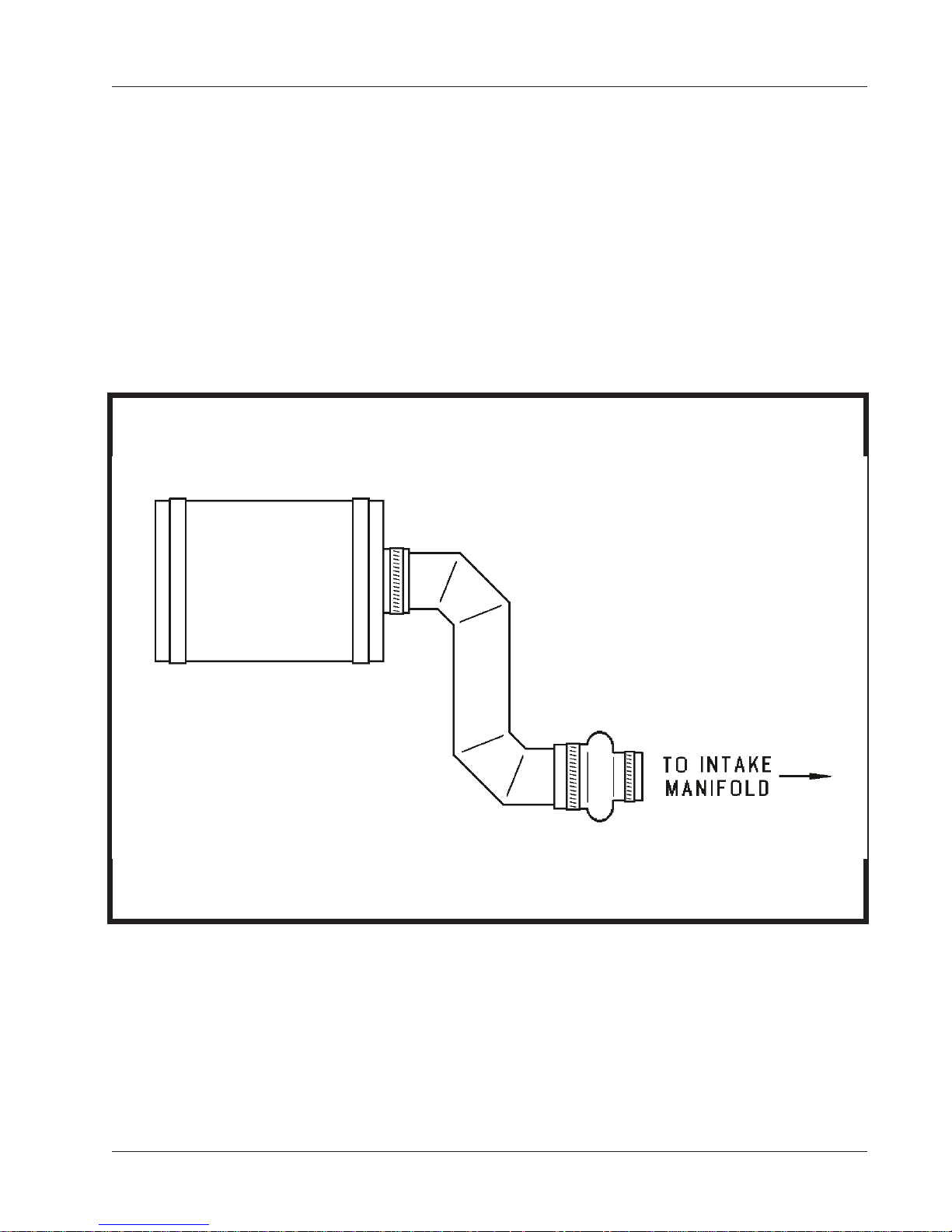
(4) Air cleaner
OM-2053
The diesel-engine air cleaner
lindrical body of the air cleaner itself, and is filtered in the process before being passed on to the
engine intake manifold assembly.
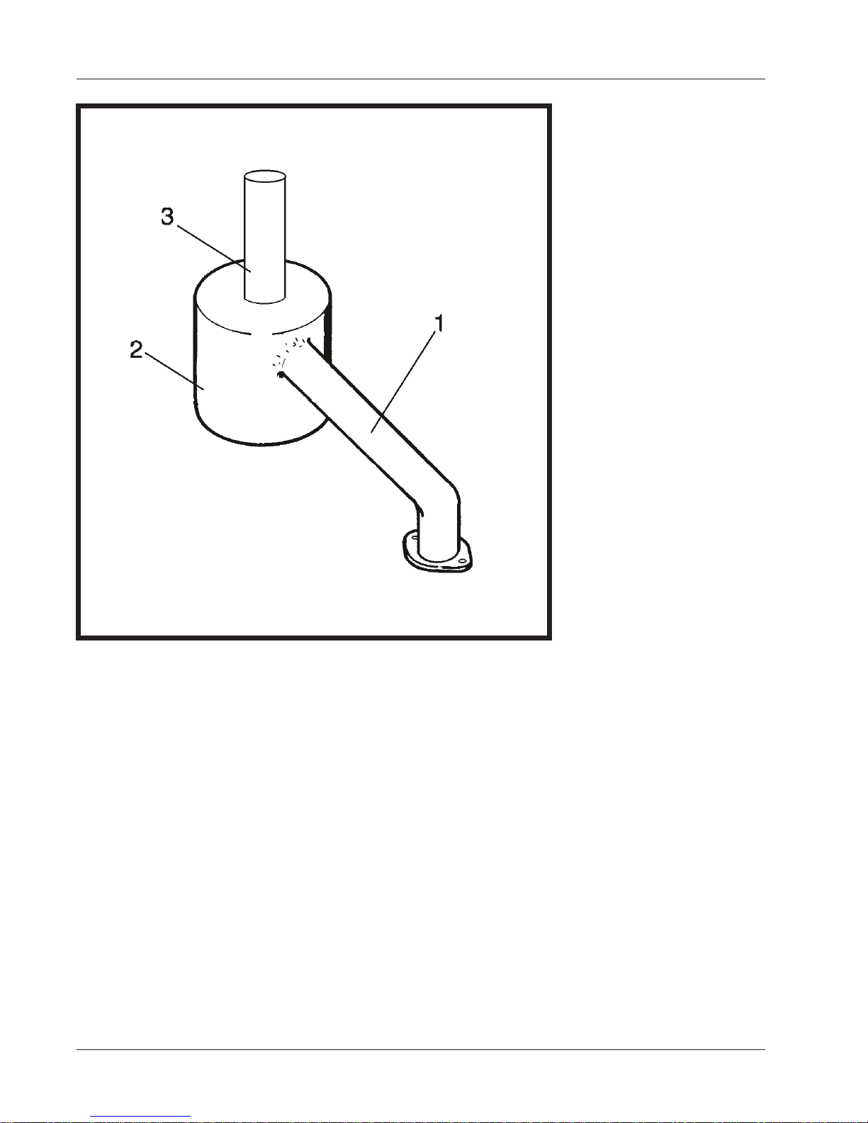
(5) Exhaust system
The exhaust system consists of a noise reducing muffler
(1)
to the exhaust manifold. The tail pipe
(6) Radiator
This radiator is a one-piece item designed for long periods of operation without servicing. Refer
to Section 2-1, Para. 7, G, for servicing procedure.
(11, Fig. 3)
(Fig. 4)
is so constructed that air enters it through the perforated cy-
(2, Fig.5)
(3)
directs exhaust and noise upward.
which is connected by a pipe
December 31/91 Revised 1-1
Air Cleaner
Figure 4
Page 7
OM-2053
1. Pipe, manifold-to-muffler
2. Muffler
3. Tail Pipe
Exhaust System
Figure 5
D. Generator
The 400-Hz generator is a brushless, revolving field, three-phase, alternating current type. The rotor
assembly is mounted by two, permanently lubricated, sealed, ball bearings. The front bearing is supported by the fan housing; the rear bearing is mounted in the exciter housing. Both of these housings
are attached to the main generator stator housing. The front end of the rotor shaft extends forward beyond the rear bearing and into the exciter stator housing. The exciter rotor is mounted on this shaft extension with a Woodruff key and is secured by a washer and 1/2"-13 thd, cap screw. A rectifier with
six diodes is mounted on the exciter rotor and converts exciter AC output to DC for excitation of the
generator revolving fields. The exciter DC output to the generator fields, and consequently the generator output, is controlled by the amount of DC voltage supplied to exciter fields by the static voltage
regulator. A centrifugal, radial-blade fan which is part of the hub and coupling assembly, draws cooling air over all internal windings. Air enters at the exciter end and is discharged at the drive end. The
complete generator is bolted to the engine flywheel housing.
1-1 December 31/91 Revised
Page 8

E. Control Box Assembly
OM-2053
The control box
generator controls, and engine and generator monitoring equipment. For access to components
mounted inside the control box, it is necessary to remove two 1/4 X 20 - 1/2-inch hex bolts, and to pull
down the front panel, which is hinged to the control box at the bottom.
(1) Front Panel
(a) Generator output monitors (meters)
The generator output is monitored by three instruments; a frequency meter
(3)
quency of the generator output alternating current in the range of 380 to 420 Hz
second)
B-N and C-N)
(5)
has a 3-1/2-inch face and the scale is graduated 0 to 300 V. The ammeter is also 3-1/2-inch
sizeandisgraduated0to500A.Theamperagevalueineachofthethreephasesmaybe
read on the ammeter by selecting the desired phase with switch
transformers, located beneath the generator control box support panel, lower the output load
current to a lesser value, of definite ratio, which will operate the ammeter movement without
damage. The ammeter dial scale is graduated and numbered so that the pointer w ill indicate
the true load current value rather than the meter movement current.
(b) Meter and line switches
These switches provide a means of selecting and determining which phase of voltage and
current is indicated on the voltmeter and ammeter and whether the voltage is line-to-neutral
or line-to-line The meter switch
der the switch knob, is marked and lettered to indicate the three functional positions of the meter switch.
is a two-position, toggle switch used to select either line-to-neutral or line-to-line voltage to the
voltmeter. The nameplate is also marked to indicate position of this switch.
(Fig. 6)
, and an ammeter
. The voltmeter indicates the generator output voltage in each phase-to-neutral
and the line selector switch
is a sheet metal enclosure which houses and provides mounting facilities for
(4)
The frequency meter is a resonant-reed type, and indicates the fre-
or phase-to-phase
(A-B, B-C and C-A)
as selected by the meter selector switch
(7).(These switches will be described below.)
(5)
. Three ammeter current
(5)
is a four-position, rotary type. A nameplate
(When the knob is pointing straight DOWN, the switch is OFF.)
The line switch
(2)
, a voltmeter
(cycles per
The voltmeter
(6)
, located un-
(A-N,
(7)
(c) Instrument light
A shielded, instrument panel light
nate controls, instruments, and indicator lights. It is controlled by a toggle switch on the engine control panel
(d) Indicating lights
The function of these lights
mal condition of overvoltage, underfrequency, etc., which caused the protective monitor system to function. Each of the five lights is connected to an actuating circuit within the memory
and time delay module. When one of the circuits is activated, it turns on the applicable indicating light. The light will remain on until the reset switch
lights may be tested by pressing switch
(2) Control box internal components
Internally, the control box contains a solid-state voltage regulator, and electrical and safety devices designed to protect the aircraft electrical system against damage which could result from
overvoltage, undervoltage, overfrequency, or underfrequency. Also contained therein are devices
for the protection and control of the generator output electrical system.
(3, Fig. 8)
(1)
is mounted at the left side of the control panel to illumi-
which also controls instrument light on the engine control control.
(10, 11, 12, 13 and 14)
is to indicate, to the operator, the abnor-
(17)
is pushed. All lamps in indicating
(16).
(Figure 7)
December 31/91 Revised 1-1
Page 9
OM-2053
(a) Sensing modules
The voltage sensing module
ator output leads between the generator and load contactor. These solid-state modules sense
any abnormal condition of voltage or frequency and signal the solid-state circuitry of the memory and time delay module
craft. A solid-state overload signaling device
module and performs a function similar to the voltage and frequency sensing modules.
(4)
and frequency sensing module
(7)
to open the load contactor and disconnect output to the air-
(5)
is also connected to the protective monitor
(6)
are connected to gener-
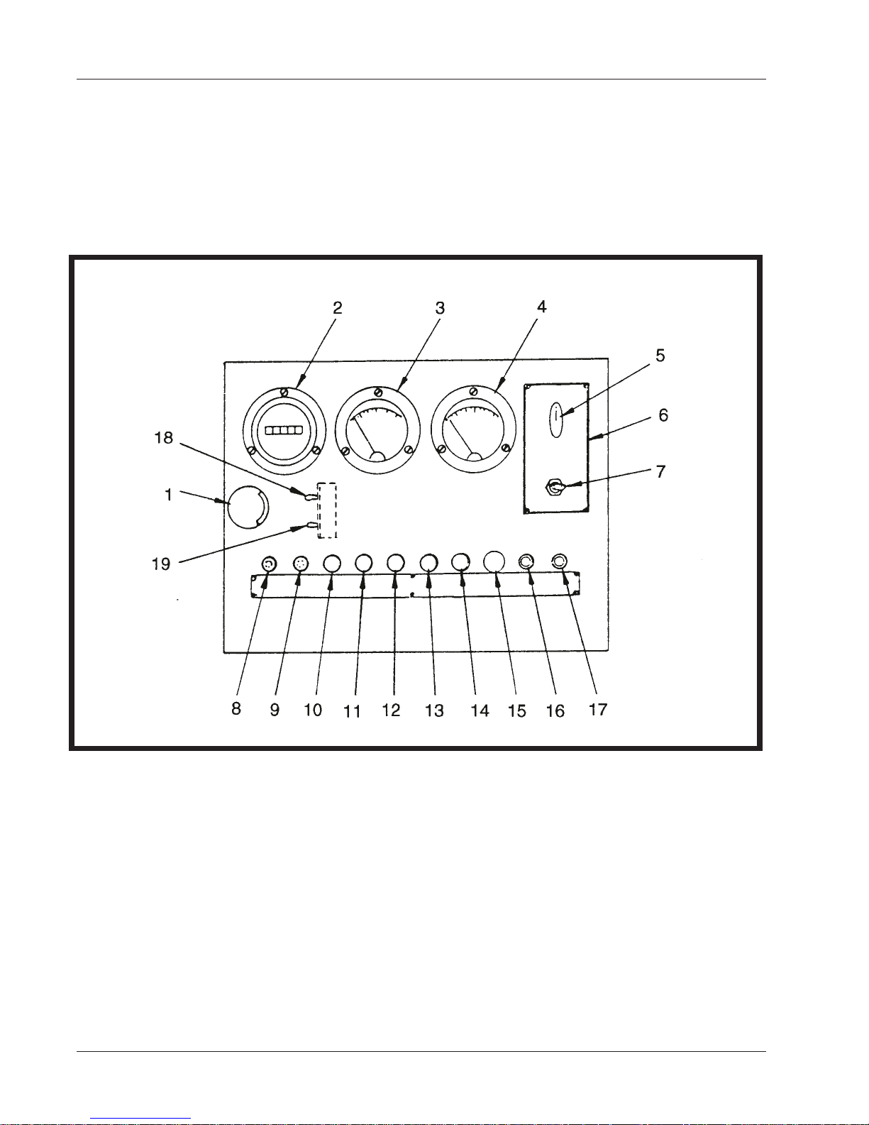
1. Instrument panel light 11. Undervoltage indicating light
2. Frequency meter 12. Overfrequency indicating light
3. Voltmeter 13. Underfrequency indicating light
4. AC ammeter 14. Overload indicating light
5. Meter selector rotary switch 15. Hole plug
6. Instruction plate 16. Light test switch
7. Line selector toggle switch 17. Reset switch
8. Protective system fuse (2-A) 18. Regulated/diagnostic switch
9. Load contactor circuit fuse (2-A) 19. Aircraft/test-bank switch
10. Overvoltage indicating light
1-1 December 31/91 Revised
Page 10
Front Panel of Generator Control Box
Figure 6

Trip values for protective circuits are as follows:
Overvoltage trips at 130 V to 134 V
Undervoltage trips at 102 V or below
Overfrequency trips at 415 Hz to 425 Hz
Underfrequency trips at 390 Hz to 395 Hz
OM-2053
Undervoltage time delay
Overload circuit trips at any value over 125% rated load capacity.
Trip values are adjustable, however, adjustments should be made ONLY under laboratory
conditions.
(3)
SeePara6,H,
(b) Memory and time delay module
The memory and time delay module
is a solid-state device with a hermetically-sealed, reed-type relay. The printed circuit board or
“card” includes five memory circuits and a time delay circuit. Each circuit is connected to a
corresponding sensing circuit in the sensing modules
connected to the module relay coil, and any one of the circuits can energize the coil to open
the relay contacts. Thus, when a sensing device energizes any one of the module circuits, the
module relay is also energized to break the load contactor holding circuit and allow the load
contactor to open. The module relay will remain energized
ON until the reset switch
the relay to return to normal, CLOSED position. All circuits, except the undervoltage circuit,
function immediately to open the load contactor. A time delay system is designed into the undervoltage circuit to prevent nuisance opening of the contactor under conditions of momentary undervoltage in the generator output. An undervoltage condition which continues
uninterrupted for a period of 4 to 12 seconds
open the load contactor. Each of the five circuits is connected to a corresponding indicating
light
(10, 11, 12, 13 and 14)
(c) Excitation-deenergization relay
for more specific and detailed information regarding overload device.
(adjustable)
(7)
is sometimes called the protective monitor module. It
(4,5,and6)
(OPEN)
(17, Fig. 6)
whichisturnedonwhenafaultoccurs.
is pushed to break the module 12-V DC cirucit, and allow
(adjustable)
will cause the time delay circuit to
. All memory circuits are
and the light will remain
The purpose of this relay
field only when engine speed is being controlled by the electric governor.
(d) Plug-interlock relay
The function of the plug interlock relay
event the cable plug connector becomes accidentally disconnected from the aircraft during
power delivery, or if an attempt is made to deliver power when the output cable is not connected to the aircraft. Twenty-eight-volt, direct current for operation of the relay is supplied
from the aircraft either through an on-board transformer-rectifier, or from a twenty-eight-volt,
electrical system. Connection from the aircraft to the interlock relay is made through terminals E and F on the output cable plug connector.
(e) Test-bank switch
A spst, toggle switch
supplying power to a load bank or to an aircraft not equipped with a plug interlock system.
(f) Resistor
A 100-ohm, 25-watt resistor
the relay in the event that phase C contacts in t he load contactor should fail to close when the
generator ON switch is operated.
December 31/91 Revised 1-1
(1)
is to allow automatic excitation to be connected to the exciter
(2)
is to cause the output load contactor to open in the
(19)
provides a means of bypassing the plug interlock relay
(18)
is connected in series with the plug interlock relay to protect
(2)
when
Page 11

OM-2053
(g) Fuse-interlock relay
The function of the fuse-interlock relay
andremovetheloadincaseofa“blown”fuse
(h) Auxiliary underfrequency relay
The function of the auxiliary underfrequency relay
deenergization relay and disconnect the voltage regulator any time generator frequency
drops to 380 Hz or below. This protects the voltage regulator PC board
overload which could be caused by high voltage regulator output in its attempt to maintain
voltage when the generator is operating at a speed which cannot produce normal voltage output.
(8)
is to interrupt the load contactor holding coil circuit
(8,Fig.6)
in the protective relay coil circuit.
(9)
is to automatically open the excitation-
(13, Fig. 7)
against
NOTE: If the auxiliary underfrequency relay is tripped, it will be necessary to momentarily
place engine operating mode switch (5, Fig. 8) in
BUILD-UP-VOLTAGE
position to restore
generator voltage.
(j ) Terminal boards
Two terminal boards
(k) Solid-state voltage regulator
This voltage regulator consists of two assemblies, a line-drop compensation assembly
and a voltage regulator PC board
is provided in Solid State Regulator Manual OM-2020, which is a part of Chapter 6 of this
manual.
(l) Overload module
See Para. 6, H,
(14)
provide connection facilities for small leads.
(13).
A full and working description of this voltage regulator
(5)
(3)
for functional description of the overload module.
(17)
(m) Rectifier
See Para. 6, H,
F. Engine Control Panel (See Fig. 8)
The engine control panel is mounted directly below the control box. Along with engine controls and instruments, generator output controls are mounted here. A plexiglas window in the canopy rear door,
slants outward at the bottom t o form an opening for access to controls when the door is closed.
(1) Engine instruments
Engine operation is monitored by an ammeter
sure gage
(a) Ammeter
The ammeter
system. Its graduated range is from -60 A through 0 A, to +60 A.
(b) Temperature gage
The temperature gage
mounted indicating mechanism which is connected by a capillary tube to a bulb mounted in
the engine cooling system. The gage indicates engine coolant temperature in the range of
100F to 220F.
(10)
(10).
An hourmeter
(4)
for functional description of the load contactor rectifier.
(4)
a coolant temperature gage
(6)
records engine operating time.
(4)
indicates the direction and value of current flow in the 12-V DC electrical
(8)
is a mechanical type of unit construction. It consists of a panel
(8),
and an oil pres-
1-1 December 31/91 Revised
Page 12
OM-2053
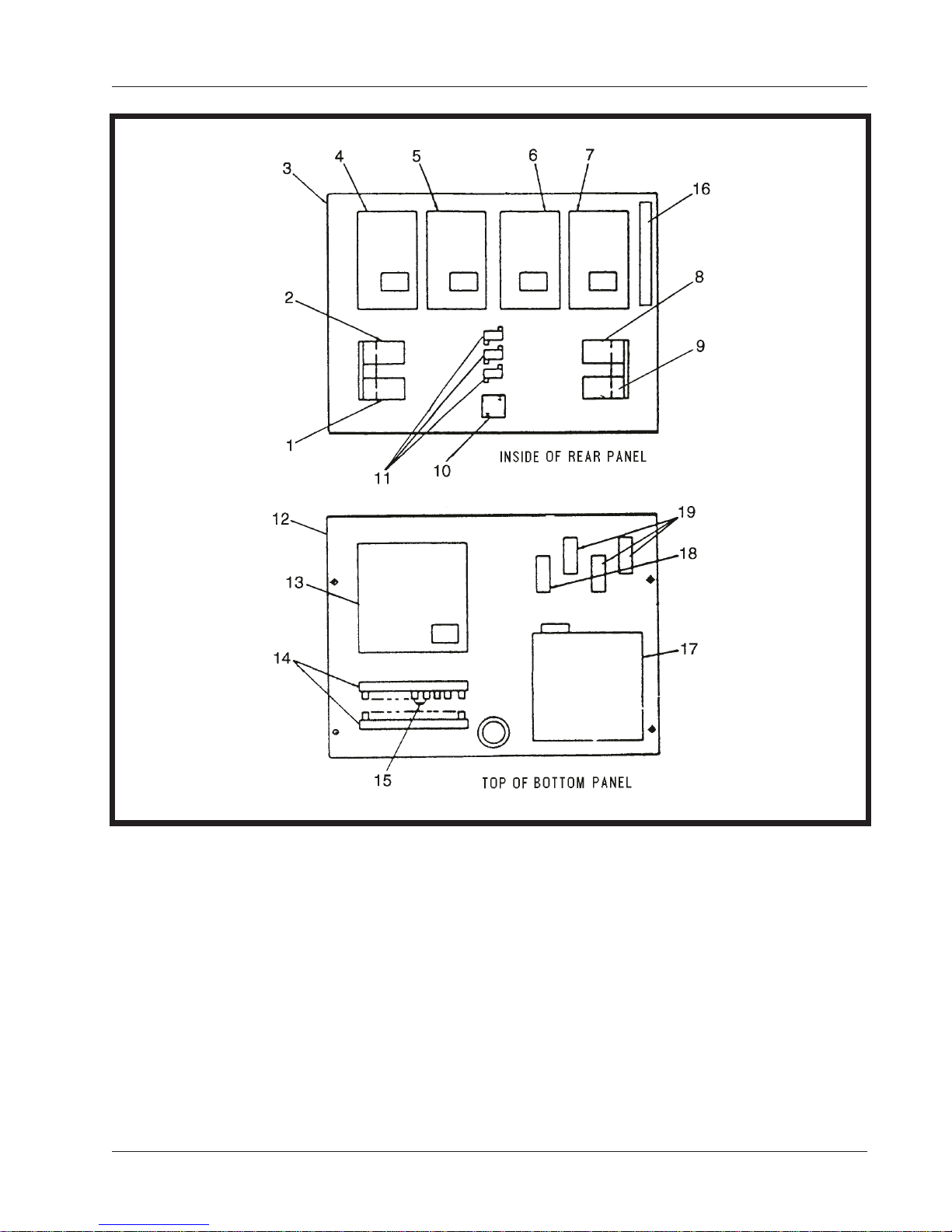
1. Excitation-deenergization relay 12. Bottom interior panel
2. Plug-interlock relay 13. Voltage regulator PC board
3. Rear interior panel 14. Terminal strips
4. Over-undervoltage module 15. Blocking diode assembly
5. Overload module 16. Ballast resistor,
6. Over-underfrequency module 20 ohm, 100 watt
7. Memory and time delay module 17. Line drop compensator
8. Fuse-interlock relay assembly
9. Auxiliary underfrequency relay 18. Resistor, 100 ohm, 25 watt
10. Contactor rectifier 19. Line drop burden resistors,
11. Overload burden resistors, 50 ohm, 25 watt
16.6 ohm, 25 watt
December 31/91 Revised 1-1
Control Box Internal Components
Figure 7
Page 13

OM-2053
(c) Oil pressure gage and oil pressure switch
The oil pressure gage
sure. It is graduated from 0 PSI to 75 PSI. An oil p ressure switch is mounted in a tee fitting directly behind the gage. This switch connects 12-V DC power to the engine control system
and to the generator 12-V DC control system when the engine is running.
(d) Hourmeter
The hourmeter
measures and records engine running time and will record up to 9999.9 hours on five revolving drums. The hourmeter operates only when the engine is running and the oil pressure
switch is closed.
(e) Fuel gage and blocking diodes
An electric fuel gage
for the generator set. A sending unit mounted in the trailer or truck mounted unit fuel tank supplies the signal to the gage. Twelve-volt DC operating power is supplied to the fuel gage from
two sources. The gage functions when the engine is running, or when the instrument lights
are ON. Since two power sources are connected to the fuel gage system, a blocking diode is
required in each power source circuit. One diode prevents energizing the motor-generator
control circuit when panel lights are ON. Another diode prevents operation of the panel lights
by the engine-generator circuit when the engine is running.
(6)
(10)
is electrically driven from the 12-V DC battery system. The hourmeter
(2, Fig. 8)
Chapter 6 for location of these diodes).
switch to turn on panel lights.
(2) Engine and generator controls
(a) Engine-generator control switch
is a bourdon tube type and indicates engine lubricating oil pres-
accurately indicates the quantity of fuel oil in the tank provided
(See Connection Diagram
To check fuel quantity when engine is stopped, use
in
The engine-generator control switch
idle” switch)
VOLTAGE, and will automatically reposition to GENERATE position when released. In
BUILD-UP-VOLTS position it performs a dual function. First, it supplies power to the gover-
nor control box, which allows the engine to operate at normal governed speed; second, it momentarily supplies current for closing the excitation-deenergization relay
to make three-phase, 115-V AC power available to the voltage regulator, or to the regulateddiagnostic circuit, for excitation of the generator exciter. In GENERATE position, power is
maintained to the governor control box and to the excitation relay
is placed in IDLE position, power is disconnected so that the engine returns to idle speed and
the exciter field is deenergized.
(b) Contactor control switch
This is another three-position, toggle switch
trol switch. When placed in the spring loaded CLOSE position, it provides 115-V AC power di-
rectly to a rectifier which supplies DC power for closing the load contactor. When released it
returns to the normal ON position and continues to provide power to the rectifier, but in this
switch position, AC power must pass through the plug interlock and fuse interlock relays. In
OFF position the switch opens the AC circuit to the rectifier, thereby cutting off the source of
DC power to the contactor coil which allows the contactor to open.
(c) Instrument light and switch
A shielded, instrument panel light
trolled by a toggle switch
is a three-position toggle type. It is spring-loaded in one position, BUILD-UP-
(3)
, which also controls instrument lights on the control box.
(5) (also identified as the “build-up-voltage, generate,
(1, Fig. 7)
(1, Fig. 7).
(7,Fig.8)
(1)
is mounted at the left side of the control panel. It is con-
identical to the engine-generator con-
contacts,
When the switch
1-1 December 31/91 Revised
Page 14

(d) Engine starting circuit
OM-2053
The pushbutton start switch
the starter solenoid which functions to engage the starter gear with the flywheel ring gear and
apply power to the starter motor to crank the engine. The permissive toggle switch
stops the engine when the toggle is placed in the STOP
(e) Indicating lights
A green indicating light
system. The light operates only when the engine permissive start switch
or RUN position. Another green indicating light
load contactor is CLOSED and power is available at the generator output cables.
(f) Fuse
A 10-ampere fuse
light circuit, and 12-V DC system in the main generator protective system.
G. Load Contactor Circuit Components
Load contactor circuit components are located either attached beneath the control box support panel,
on the trailer assembly, or inside the generator control box. The load contactor and its associated circuit components provide a means of connecting and disconnecting generator output to and from the
load
(aircraft)
(1) Load contactor
The load contactor
sets of contacts. The three larger contacts conduct three-phase AC generator output. A smaller
contact set is connected in the protective monitor circuit and supplies 12-V DC power used by
sensing relays to signal the protective monitor when a fault occurs. Three-phase, 400-Hz generator output power is conducted to the load contactor by 2/0 cables which pass through 3 sets of
current transformers.
.
(11)
(3, Fig. 9)
(13
) and permissive toggle switch
(15)
serve to connect power to
(15)
(down)
(12)
glows to indicate that power is available to the engine protective
(9, Fig. 8)
protects the 12-V DC engine control circuit, hourmeter, illuminating
is a sealed unit which contains a magnetic operating coil and four
position.
(15)
is in the START
glows when the generator output
also
(2) Current transformers
These current transformers are located beneath the control box support panel directly below the
control box.
(a) Ammeter current transformers
Three current transformers lower the output load current to a lesser value of definite ratio
(250-A to 5-A)
meter dial scale is graduated and numbered so that the ammeter pointer will indicate the true
load current value rather than the meter movement current.
(b) Line-drop current transformers
The three line-drop current transformers in conjunction with burden resistors, detect the magnitude and power factor of current flowing from generator to load. They feed a signal to the
voltage regulator which interprets the signal and alters the exciter field current as required to
maintain a constant predetermined voltage at the load.
(c) Overload current transformers
Three overload current transformers, in conjunction with burden resistors monitor the output
load current in each of the three output phases, and supply a reduced value current signal to
theoverloadmodule
which will operate the ammeter
(5, Fig 7)
(2,Fig.10)
(3, Fig. 10)
(4, Fig. 10)
(4,Fig.6)
movement without damage. The am-
December 31/91 Revised 1-1
Page 15
OM-2053
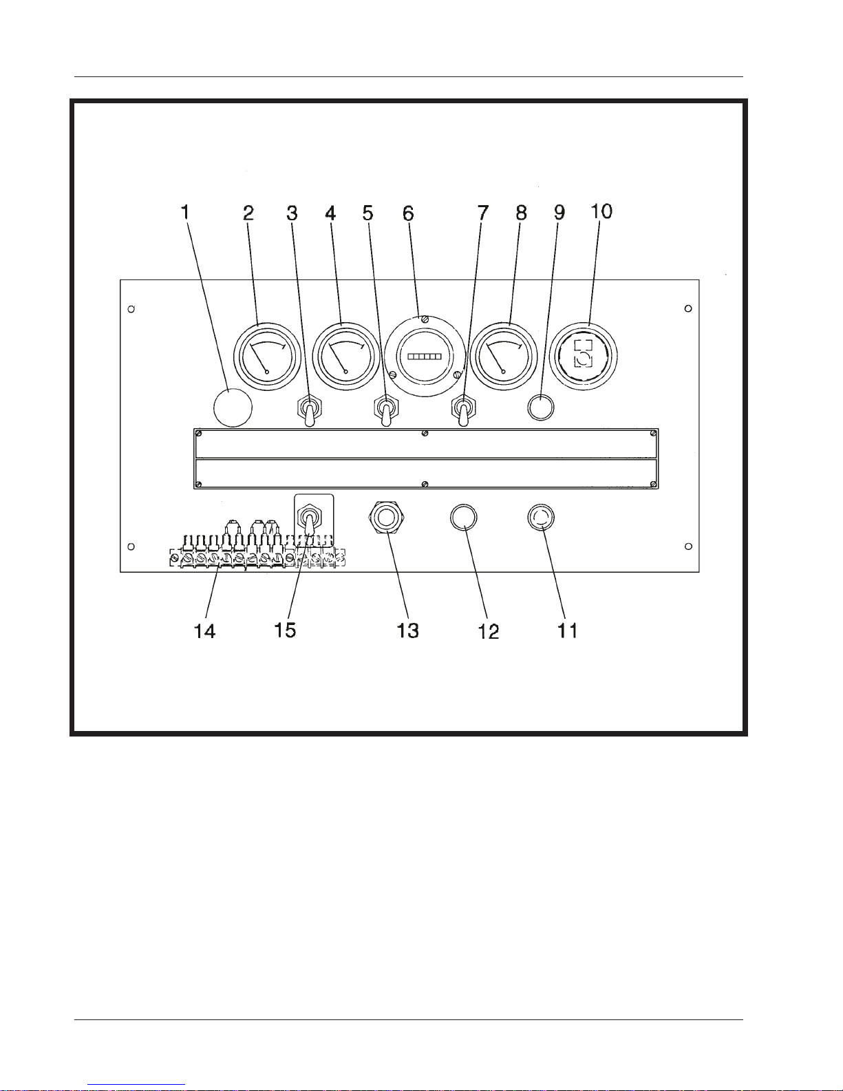
1. Panel light 9.Load contactor indicating light
2. Fuel gage 10. Engine oil pressure gage
3. Light switch 11. Engine circuit fuse (10-A)
4. DC Ammeter 12. Engine “ON” indicating light
5. Engine-generator control switch 13. Engine starter switch
6. Hourmeter 14. Terminal strip (behind panel)
7. Load contactor control switch 15. Permissive start switch
8. Coolant temperature gage
1-1 December 31/91 Revised
Page 16
Engine Control Panel
Figure 8
 Loading...