

Page 1
Model Reciprocating Saw
Modèle Scie alternative
Modelo Sierra reciprocante
CR 13VBY
INSTRUCTION MANUAL AND SAFETY INSTRUCTIONS
WARNING
Improper and unsafe use of this power tool can result in death or serious bodily injury!
This manual contains important information about product safety. Please read and
understand this manual before operating the power tool. Please keep this manual
available for others before they use the power tool.
MODE D’EMPLOI ET INSTRUCTIONS DE SECURITE
AVERTISSEMENT
Une utilisation incorrecte et dangereuse de cet outil motorisé peut entraîner la mort ou
de sérieuses blessures corporelles!
Ce mode d’emploi contient d’importantes informations à propos de la sécurité de ce
produit. Prière de lire et de comprendre ce mode d’emploi avant d’utiliser l’outil
motorisé. Garder ce mode d’emploi à la disponibilité des autres utilisateurs avant qu’ils
utilisent l’outil motorisé.
MANUAL DE INSTRUCCIONES E INSTRUCCIONES DE SEGURIDAD
ADVERTENCIA
¡La utilización inapropiada e insegura de esta herramienta eléctrica puede resultar en
lesiones serias o en la muerte!
Este manual contiene información importante sobre la seguridad del producto. Lea y
comprenda este manual antes de utilizar la herramienta eléctrica. Guarde este manual
para que puedan leerlo otras personas antes de que utilicen la herramienta eléctrica.
DOUBLE INSULATION
DOUBLE ISOLATION
AISLAMIENTO DOBLE
Page 2

English
IMPORTANT INFORMATION ............................... 3
MEANINGS OF SIGNAL WORDS ........................ 3
SAFETY ...................................................................... 4
GENERAL SAFETY RULES ................................... 4
SPECIFIC SAFETY RULES AND SYMBOLS ......... 6
DOUBLE INSULATION FOR SAFER
OPERATION ................................................... 7
FUNCTIONAL DESCRIPTION .................................... 8
NAME OF PARTS .................................................. 8
SPECIFICATIONS .................................................. 8
CONTENTS
Page Page
ASSEMBLY AND OPERATION ................................. 9
APPLICATIONS ..................................................... 9
PRIOR TO OPERATION ......................................... 9
HOW TO USE THE RECIPROCATING SAW ...... 13
MAINTENANCE AND INSPECTION ....................... 17
ACCESSORIES ......................................................... 18
STANDARD ACCESSORIES ............................... 18
OPTIONAL ACCESSORIES ................................. 19
PARTS LIST .............................................................. 56
Français
INFORMATIONS IMPORTANTES ...................... 20
SIGNIFICATION DES MOTS
D’AVERTISSEMENT .................................... 20
SECURITE ................................................................ 21
REGLES GENERALE DE SECURITE ................... 21
REGLES DE SECURITE SPECIFIQUES ET
SYMBOLES .................................................. 23
DOUBLE ISOLATION POUR UN
FONCTIONNEMENT PLUS SUR ................. 24
DESCRIPTION FONCTIONNELLE ........................... 26
NOM DES PARTIES ............................................ 26
SPECIFICATIONS ................................................ 26
Español
INFORMACIÓN IMPORTANTE ........................... 38
SIGNIFICADO DE LAS PALABRAS DE
SEÑALIZACIÓN ............................................ 38
SEGURIDAD ............................................................. 39
NORMAS GENERALES DE SEGURIDAD........... 39
NORMAS Y SÍMBOLOS
ESPECÍFICOS DE SEGURIDAD ................... 41
AISLAMIENTO DOBLE PARA OFRECER
UNA OPERACIÓN MÁS SEGURA .............. 42
DESCRIPCIÓN FUNCTIONAL ................................. 44
NOMENCLATURA ............................................... 44
ESPECIFICACIONES ............................................ 44
TABLE DES MATIERES
Page Page
Página Página
ASSEMBLAGE ET FONCTIONNEMENT ................ 27
ENTRETIEN ET INSPECTION .................................. 35
ACCESSOIRES ......................................................... 36
LISTA DES PIÈCES .................................................. 56
ÍNDICE
MONTAJE Y OPERACIÓN ...................................... 45
MANTENIMIENTO E INSPECCIÓN ........................ 53
ACCESORIOS ........................................................... 54
LISTA DE PIEZAS ................................................... 56
APPLICATIONS ................................................... 27
AVANT L’UTILISATION ...................................... 27
COMMENT UTILISER LA SCIE
ALTERNATIVE .............................................. 32
ACCESSOIRES STANDARD ............................... 36
ACCESSOIRES SUR OPTION ............................. 37
APLICACIONES ................................................... 45
ANTES DE LA OPERACIÓN ................................ 45
COMO USAR LA SIERRA RECIPROCANTE ....... 50
ACCESORIOS ESTÁNDAR ................................. 54
ACCESORIOS OPCIONALES .............................. 55
Page 3

English
IMPORTANT SAFETY INFORMATION
Read and understand all of the safety precautions, warnings and operating instructions in
the Instruction Manual before operating or maintaining this power tool.
Most accidents that result from power tool operation and maintenance are caused by the
failure to observe basic safety rules or precautions. An accident can often be avoided by
recognizing a potentially hazardous situation before it occurs, and by observing appropriate
safety procedures.
Basic safety precautions are outlined in the “SAFETY” section of this Instruction Manual
and in the sections which contain the operation and maintenance instructions.
Hazards that must be avoided to prevent bodily injury or machine damage are identified by
WARNINGS on the power tool and in this Instruction Manual.
NEVER use this power tool in a manner that has not been specifically recommended by
HITACHI.
MEANINGS OF SIGNAL WORDS
WARNING indicates a potentially hazardous situations which, if ignored, could result in
death or serious injury.
CAUTION indicates a potentially hazardous situations which, if not avoided, may result in
minor or moderate injury, or may cause machine damage.
NOTE emphasizes essential information.
3
Page 4

English
SAFETY
GENERAL SAFETY RULES
WARNING: Read all instructions
Failure to follow all instructions listed below may result in electric shock,
fire and/or serious injury.
The term “power tool” in all of the warnings listed below refers to your
mains-operated (corded) power tool or battery-operated (cordless)
power tool.
SAVE THESE INSTRUCTIONS
1) Work area safety
a) Keep work area clean and well lit.
Cluttered or dark areas invite
accidents.
b) Do not operate power tools in
explosive atmospheres, such as in
the presence of flammable liquids,
gases or dust.
Power tools create sparks which
may ignite the dust of fumes.
c) Keep children and bystanders away
while operating a power tool.
Distractions can cause you to lose
control.
2) Electrical Safety
a) Power tool plugs must match the
outlet.
Never modify the plug in any way.
Do not use any adapter plugs with
earthed (grounded) power tools.
Unmodified plugs and matching
outlets will reduce risk of electric
shock.
b) Avoid body contact with earthed or
grounded surfaces such as pipes,
radiators, ranges and refrigerators.
There is an increased risk of electric
shock if your body is earthed or
grounded.
c) Do not expose power tools to rain
or wet conditions.
4
Water entering a power tool will
increase the risk of electric shock.
d) Do not abuse the cord. Never use
the cord for carrying, pulling or
unplugging the power tool.
Keep cord away from heat, oil,
sharp edges or moving parts.
Damaged or entangled cords
increase the risk of electric shock.
e) When operating a power tool
outdoors, use an extension cord
suitable for outdoor use.
Use of a cord suitable for outdoor
use reduces the risk of electric
shock.
3) Personal safety
a) Stay alert, watch what you are
doing and use common sense when
operating a power tool.
Do not use a power tool while you
are tired or under the influence of
drugs, alcohol or medication.
A moment of inattention while
operating power tools may result in
serious personal injury.
b) Use safety equipment. Always wear
eye protection.
Safety equipment such as dust
mask, non-skid safety shoes, hard
hat, or hearing protection used for
appropriate conditions will reduce
personal injuries.
Page 5

English
c) Avoid accidental starting. Ensure the
switch is in the off position before
plugging in.
Carrying power tools with your
finger on the switch or plugging in
power tools that have the switch on
invites accidents.
d) Remove any adjusting key or
wrench before turning the power
tool on.
A wrench or a key left attached to a
rotating part of the power tool may
result in personal injury.
e) Do not overreach. Keep proper
footing and balance at all times.
This enables better control of the
power tool in unexpected situations.
f) Dress properly. Do not wear loose
clothing or jewellery. Keep your
hair, clothing and gloves away from
moving parts.
Loose clothes, jewellery or long hair
can be caught in moving parts.
g) If devices are provided for the
connection of dust extraction and
collection facilities, ensure these are
connected and properly used.
Use of these devices can reduce
dust-related hazards.
4) Power tool use and care
a) Do not force the power tool. Use the
correct power tool for your
application.
The correct power tool will do the
job better and safer at the rate for
which it was designed.
b) Do not use the power tool if the
switch does not turn it on and off.
Any power tool that cannot be
controlled with the switch is
dangerous and must be repaired.
c) Disconnect the plug from the power
source and/or the battery pack from
the power toll before making any
adjustments, changing accessories,
or storing power tools.
Such preventive safety measures
reduce the risk of starting the power
tool accidentally.
d) Store idle power tools out of the
reach of children and do not allow
persons unfamiliar with the power
tool or these instructions to operate
the power tool.
Power tools are dangerous in the
hands of untrained users.
e) Maintain power tools. Check for
misalignment or binding of moving
parts, breakage of parts and any
other condition that may affect the
power tools operation.
If damaged, have the power tool
repaired before use.
Many accidents are caused by
poorly maintained power tools.
f) Keep cutting tools sharp and clean.
Properly maintained cutting tools
with sharp cutting edges are less
likely to bind and are easier to
control.
g) Use the power tool, accessories and
tool bits etc., in accordance with
these instructions and in the
manner intended for the particular
type of power tool, taking into
account the working conditions and
the work to be performed.
Use of the power tool for operations
different from intended could result
in a hazardous situation.
5) Service
a) Have your power tool serviced by a
qualified repair person using only
identical replacement parts.
This will ensure that the safety of the
power tool is maintained.
–WARNING–
To reduce the risk of injury, user must read
instruction manual.
5
Page 6
English
SPECIFIC SAFETY RULES AND SYMBOLS
1. Hold power tool by insulated gripping
surfaces when performing an operation
where the cutting tool may contact
hidden wiring or its own cord. Contact
with a “live” wire will make exposed
metal parts of the tool “live” and shock
the operator.
2. Use clamps or another practical way to
secure and support the workpiece to a
stable platform. Holding the work by
hand or against your body leaves it
unstable and may lead to loss of control.
3. ALWAYS wear ear protectors when
using the tool for extended periods.
Prolonged exposure to high
intensity noise can cause
hearing loss.
4. NEVER touch moving parts.
NEVER place your hands, fingers or
other body parts near the tool’s moving
parts.
5. NEVER operate without all guards in
place.
NEVER operate this tool without all
guards or safety features in place and
in proper working order. If maintenance
or servicing requires the removal of a
guard or safety feature, be sure to
replace the guard or safety feature
before resuming operation of the tool.
6. Use right tool.
Don’t force small tool or attachment to
do the job of a heavy-duty tool.
Don’t use tool for purpose not intended
—for example— don’t use circular saw
for cutting tree limbs or logs.
7. NEVER use a power tool for applications
other than those specified.
NEVER use a power tool for applications
other than those specified in the
Instruction Manual.
8. Handle tool correctly.
Operate the tool according to the
instructions provided herein. Do not
drop or throw the tool. NEVER allow the
tool to be operated by
children,individuals unfamiliar with its
operation or unauthorized personnel.
6
9. Keep all screws, bolts and covers tightly
in place.
Keep all screws, bolts, and plates tightly
mounted. Check their condition periodically.
10. Do not use power tools if the plastic
housing or handle is cracked.
Cracks in the tool’s housing or handle
can lead to electric shock. Such tools
should not be used until repaired.
11. Blades and accessories must be
securely mounted to the tool.
Prevent potential injuries to yourself or
others. Blades, cutting implements and
accessories which have been mounted
to the tool should be secure and tight.
12. Keep motor air vent clean.
The tool’s motor air vent must be kept
clean so that air can freely flow at all
times. Check for dust build-up frequently.
13. Operate power tools at the rated
voltage.
Operate the power tool at voltages
specified on its nameplate.
If using the power tool at a higher
voltage than the rated voltage, it will
result in abnormally fast motor
revolution and may damage the unit and
the motor may burn out.
14. NEVER use a tool which is defective or
operating abnormally.
If the tool appears to be operating
unusually, making strange noises, or
otherwise appears defective, stop using
it immediately and arrange for repairs
by a Hitachi authorized service center.
15. NEVER leave tool running unattended.
Turn power off.
Don’t leave tool until it comes to a
complete stop.
16. Carefully handle power tools.
Should a power tool be dropped or
struck against hard materials
inadvertently, it may be deformed,
cracked, or damaged.
17. Do not wipe plastic parts with solvent.
Solvents such as gasoline, thinner
benzine, carbon tetrachloride, and
alcohol may damage and crack plastic
parts. Do not wipe them with such
solvents.
Wipe plastic parts with a soft cloth lightly
dampened with soapy water and dry
thoroughly.
Page 7

English
18. ALWAYS wear eye protection that meets
19. ALWAYS be careful with buried object
20. Definitions for symbols used on this tool
V ............. volts
Hz ........... hertz
A .............amperes
n
W ............watt
---/min ....revolutions or recipocation per
the requirement of the latest
revision of ANSI Standard
Z87.1.
such as an underground wiring.
Touching live wiring or electric cable
with this tool may result in electric
shock.
Confirm before use whether hidden
objects are present, such as electric
cables within the wall, floor or ceiling.
o ............ no load speed
............ Class II Construction
minute
DOUBLE INSULATION FOR SAFER OPERATION
To ensure safer operation of this power tool,
HITACHI has adopted a double insulation
design. “Double insulation” means that two
physically separated insulation systems
have been used to insulate the electrically
conductive materials connected to the
power supply from the outer frame handled
by the operator. Therefore, either the symbol
“
” or the words “Double insulation”
appear on the power tool or on the
nameplate.
Although this system has no external
grounding, you must still follow the normal
electrical safety precautions given in this
Instruction Manual, including not using the
power tool in wet environments.
To keep the double insulation system
effective, follow these precautions:
䡬 Only Hitachi Authorized Service Center
should disassemble or assemble this
power tool, and only genuine HITACHI
replacement parts should be installed.
䡬 Clean the exterior of the power tool only
with a soft cloth moistened with soapy
water, and dry thoroughly.
Never use solvents, gasoline or thinners
on plastic components; otherwise the
plastic may dissolve.
SAVE THESE INSTRUCTIONS
AND
MAKE THEM AVAILABLE TO
OTHER USERS
AND
OWNERS OF THIS TOOL!
7
Page 8

English
FUNCTIONAL DESCRIPTION
NOTE: The information contained in this Instruction Manual is designed to assist you in
the safe operation and maintenance of the power tool.
NEVER operate, or attempt any maintenance on the tool unless you have first read
and understood all safey instructions contained in this manual.
Some illustrations in this Instruction Manual may show details or attachments that
differ from those on your own power tool
NAME OF PARTS
Blade holder
Lever
Blade
Base
Rubber cap
Front cover
Base lever
Push button
Change lever
Fig. 1
Brush cap
Switch trigger
Handle
Housing
Dial
SPECIFICATIONS
Motor Single-Phase, Series Commutator Motor
Power Source Single-Phase, 120 V AC 60 Hz
Current 13 A
Capacity Mild Steel Pipe: O.D. 5" (130 mm)
Vinyl Chloride Pipe: O.D. 5" (130 mm)
Wood: Depth 5" (130 mm)
No-Load Speed 0 – 3000/min.
Stroke 1-1/4" (32 mm)
Weight (without cord) 9.7 lbs (4.4 kg)
8
Page 9
ASSEMBLY AND OPERATION
English
APPLICATIONS
䡬 Cutting metal and stainless steel pipe.
䡬 Cutting various lumber.
䡬 Cutting mild steel, aluminum and
copper plate.
䡬 Cutting synthetic resins, such as phenol
resin and vinyl chloride.
PRIOR TO OPERATION
1. Power source
Ensure that the power source to be
utilized conforms to the power source
requirements specified on the product
nameplate.
2. Power switch
Ensure that the switch is in the OFF
position. If the plug is connected to a
receptacle while the switch is in the ON
position, the power tool will start
operating immediately and can cause
serious injury.
3. Extension cord
When the work area is far away from the
power source, use an extension cord of
sufficient thickness and rated capacity.
The extension cord should be kept as
short as practicable.
4. Check the receptacle
If the receptacle only loosely accepts the
plug, the receptacle must be repaired.
Contact a licensed electrician to make
appropriate repairs.
If such a fautly receptacle is used, it may
cause overheating, resulting in a serious
hazard.
WARNING:
Damaged cord must be
replaced or repaired.
5. Confirming condition of the
environment:
Confirm that the work site is placed under
appropriate conditions conforming to
prescribed precautions.
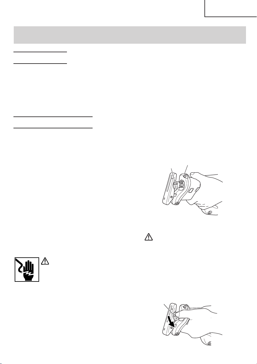
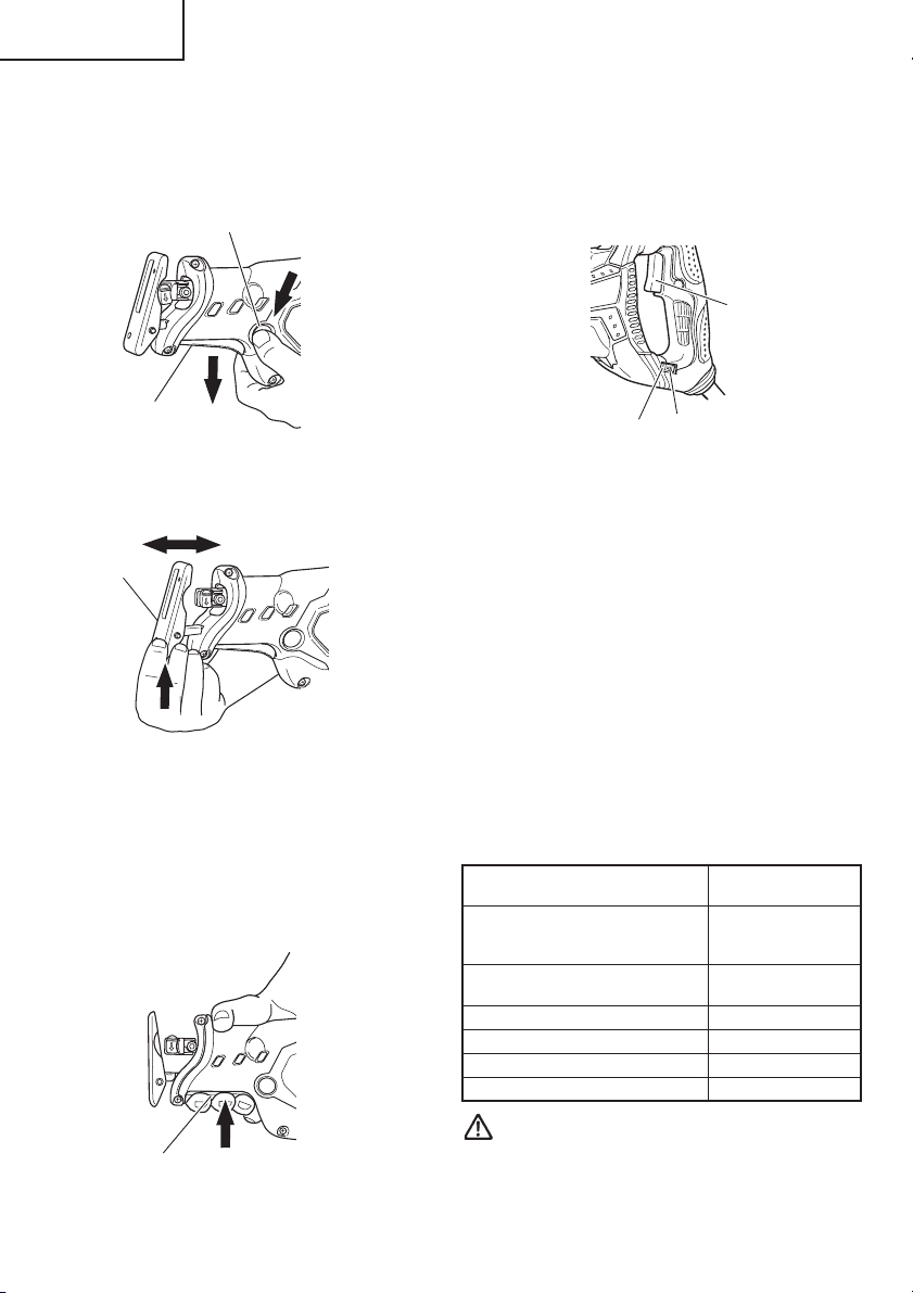
6. Mounting the blade
This unit employs a detachable
mechanism that enables mounting and
removal of saw blades without the use
of a wrench or other tools.
(1) Turn on and off the switching trigger
several times so that the lever can
jump out of the front cover
completely. Thereafter, turn off the
switch and unplug the power cord.
(Fig. 2)
Lever
CAUTION:
Be absolutely sure to keep the
switch turned off and the power
cord unplugged to prevent any
accident.
(2) Push the lever in the direction of the
arrow mark shown in Fig. 3 marked
on the lever.
Lever
Front cover
Fig. 2
Fig. 3
9
Page 10
English
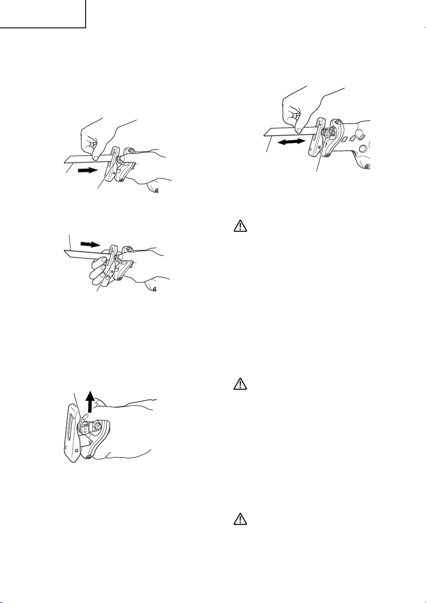
(3) Insert the saw blade all the way into
the small slit of the plunger tip with
the lever pushing. You can mount
this blade either in the upward or
downward direction. (Fig. 4, Fig. 5)
know it is properly mounted if it
clicks and the lever moves slightly.
(Fig. 7)
Blade
Blade
Slit of plunger
Blade
(4) When you release the lever, the
spring force will return the lever to
the correct position automatically.
(Fig. 6)
Lever
(5) Pull the back of the saw blade two
or three times by hand and check
that the blade is securely mounted.
When pulling the blade, you will
Fig. 4
Slit of plunger
Fig. 5
Fig. 6
Lever
Fig. 7
CAUTION:
When pulling the saw blade, be
absolutely sure to pull it from the
back. Pulling other parts of the
blade will result in an injury.
7. Dismounting the blade
(1) Turn on and off the switching trigger
several times so that the lever can
jump out of the front cover
completely. Thereafter, turn off the
switch and unplug the power cord.
(Fig. 2)
CAUTION:
Be absolutely sure to keep the switch
turned off and the power cord
unplugged to prevent any accident.
(2) After you have pushed the lever in
the direction of the arrow mark
shown in Fig. 3, turn the blade so it
faces downward. The blade should
fall out by itself. If the blade doesn’t
fall out, pull it out by hand.
CAUTION:
Never touch the saw blade
immediately after use. The metal is
hot and can easily burn your skin.
10
Page 11

English
WHEN THE BLADE IS BROKEN
Even when the saw blade is broken and
remains inside the small slit of the
plunger, it should fall out if you push the
lever in the direction of the arrow mark,
and face the blade downward. If it doesn’t
fall out itself, take it out using the
procedures explained below.
(1) If a part of the broken saw blade is
sticking out of the small slit of the
plunger, pull out the protruding part
and take the blade out.
(2) If the broken saw blade is hidden
inside the small slit, hook the broken
blade using a tip of another saw
blade and take it out. (Fig. 8)
Lever
Another blade
Slit of plunger
Fig. 8
NOTE:
Continued use of the tool without
cleaning and lubricating the area
where the saw blade is installed can
result in some slack movement of
the lever due to accumulated
sawdust and chips. Under the
circumstances, pull a rubber cap
provided on the lever in the
direction of an arrow mark as shown
in Fig. 10 and remove the rubber cap
from the lever. Then, clean up the
inside of the blade holder with air
and the like and carry out sufficient
lubrication.
The rubber cap can be fitted on if it
is pressed firmly onto the lever. At
this time, make certain that there
exists no clearance between the
blade holder and the rubber cap,
and furthermore ensure that the
saw-blade-installed area can
function smoothly.
Lever
MAINTENANCE AND INSPECTION
OF SAW BLADE MOUNT
(1) After use, blow away sawdust, earth,
sand, moisture, etc., with air or brush
them away with a brush, etc., to ensure
that the blade mount can function
smoothly.
(2) As shown in Fig. 9, carry out lubrication
around the blade holder on a periodic
basis by use of cutting fluid, etc.
Blade holder
Lever
Machine oil
Fig. 9
Rubber cap
Fig. 10
CAUTION:
Do not use any saw blade with a
worn-out blade hole. Otherwise, the
saw blade can come off, resulting
in personal injury. (Fig. 11)
Blade hole
Blade
Fig. 11
8. Adjusting the base
This unit employs a mechanism that can
adjust the base mounting position in three
11
Page 12
English
stages without the use of a wrench or
other tools.
(1) Press a pushbutton. When you do this,
a base lever will jump out to prepare
the base for adjustment (Fig. 12)
Push button
Base lever
Fig. 12
(2) Push up the base tip and jog the base
back and forth. (Fig. 13)
Base
Fig. 13
(3) You can adjust the base position in
three stages. Move the base at an
interval of about 15 mm, find the
position where the base hooks, and
press in the base lever with your
fingers. The base is secured when
you hear the clicking sound. (Fig. 14)
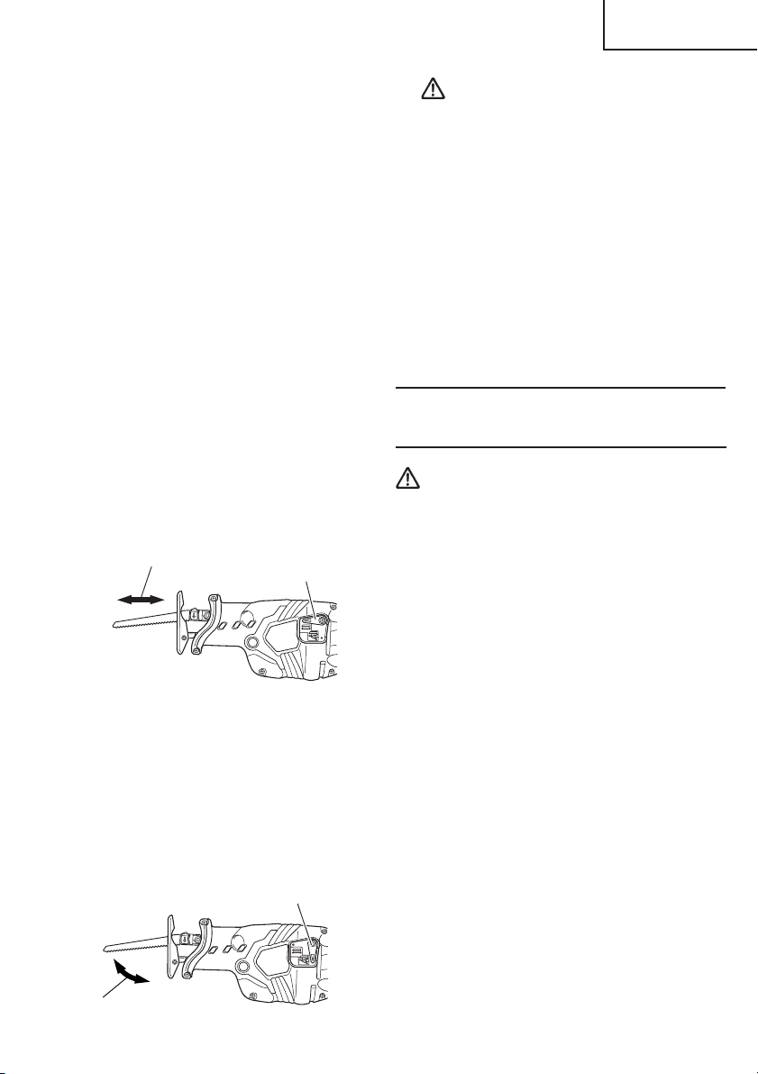
This unit has a built-in electronic control
circuit that makes it possible to adjust the
variable speed of the saw blade either
both by pulling a switching trigger or
turning a dial. (Fig. 15)
Switch
trigger
Dial
Graduation
Fig. 15
(1) If you pull the trigger further in, the
speed of the blade accelerates. Begin
cutting at a low speed to ensure the
accuracy of your target cut position.
Once you’ve obtained a sufficient
cutting depth, increase the cutting
speed.
(2) On the dial scale, “5” is the maximum
speed and “1” the minimum. The high
speed is generally suitable for soft
materials such as wood, and the low
speed is suitable for hard materials
such as metal. We recommend that
you use the following as a rough guide
in selecting the suitable speed for the
materials you are cutting.
Example of materials Recommended
to be cut dial scale
Mild steel pipes /
cast-iron tubes / 2 – 4
L-shaped angle steel
Wood / wood with nails
driven in
Stainless steel 1 – 3
Aluminum / brass / copper 2 – 4
Plaster board 4 – 5
Plastic / fiber board 1 – 3
5
Base lever
Fig. 14
9. Adjusting the blade reciprocating
speed
12
CAUTION:
䡬 When cutting at low speed (scale of 1 –
2), never cut a wooden board more than
25/64" (10 mm) thick or a mild steel plate
more than 5/64" (2 mm) thick. The load
Page 13
English
on the motor can result in overheating
and damage.
䡬 Although this unit employs a powerful
motor, prolonged use at a low speed will
increase the load unduly and may lead to
overheating. Properly adjust the saw
blade to allow steady, smooth cutting
operation, avoiding any unreasonable
use such as sudden stops during cutting
operation.
10.
Adjusting the swing cutting operation
Two cutting systems can be selected with
this unit. The first is straight cutting, in
which the saw blade is moved linearly,
and the second is the swing cutting, in
which the saw blade is swung like a
pendulum. (Fig. 16, Fig. 17)
(1) Straight cutting
You can perform straight cutting by
setting the change lever widthwise.
Straight cutting should normally be
performed when cutting hard
materials such as metal, etc. (Fig. 16)
Straight cutting
Fig. 16
(2) Swing cutting
You can perform swing cutting by
setting the change lever lengthways.
Swing cutting should normally be
performed when cutting soft materials
such as wood, etc.
Swing cutting is efficient since the
saw blade forcibly bites into the
material. (Fig. 17)
Swing cutting
Fig. 17
Change lever
Change lever
CAUTION:
䡬 Even for soft materials, you should
perform straight cutting if you wish
to make curved or clean cuts.
䡬 Dust and dirt accumulated on the
change lever section can degrade the
function of the change lever.
Periodically clean the change lever
section.
䡬 When performing swing cutting, use
a saw with straight blade. If a saw
with curved blade is used, the saw
blade may be broken or the unit may
be damaged.
HOW TO USE THE
RECIPROCATING SAW
CAUTION:
䡬 Avoid carrying it plugged to the outlet
with your finger on the switch. A
sudden startup can result in an
unexpected injury.
䡬 Be careful not to let sawdust, earth,
moisture, etc., enter the inside of the
machine through the plunger section
during operation. If sawdust and the like
accumulate in the plunger section,
always clean it before use.
䡬 Do not remove the front cover (refer to
Fig. 2).
Hold firmly the front cover by hand to
operate.
But, do not extend your hand or finger
beyond the flange (see Fig.18) of front
cover to avoid an injury.
䡬 During use, press the base against the
material while cutting.
Vibration can damage the saw blade if
the base is not pressed firmly against
the workpiece.
Furthermore, a tip of the saw blade can
sometimes contact the inner wall of the
pipe, damaging the saw blade.
13
Page 14
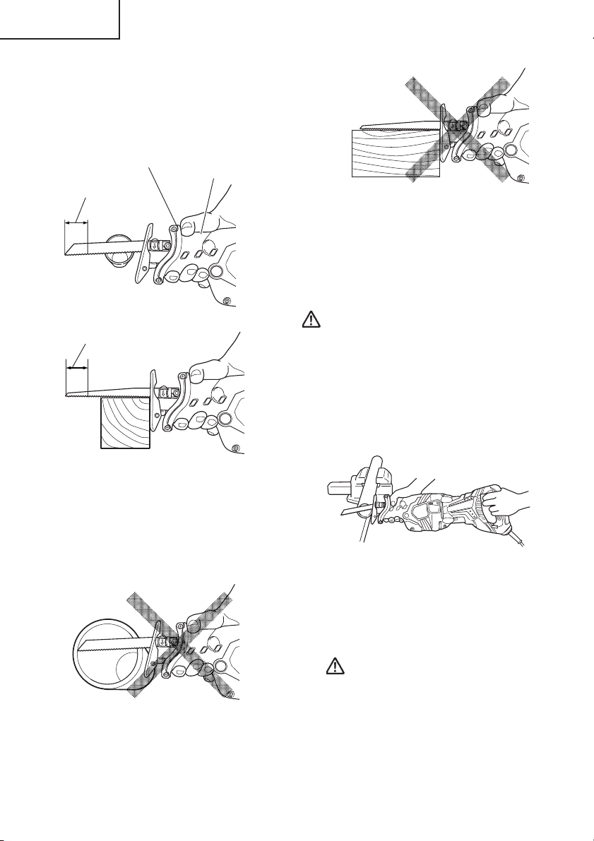
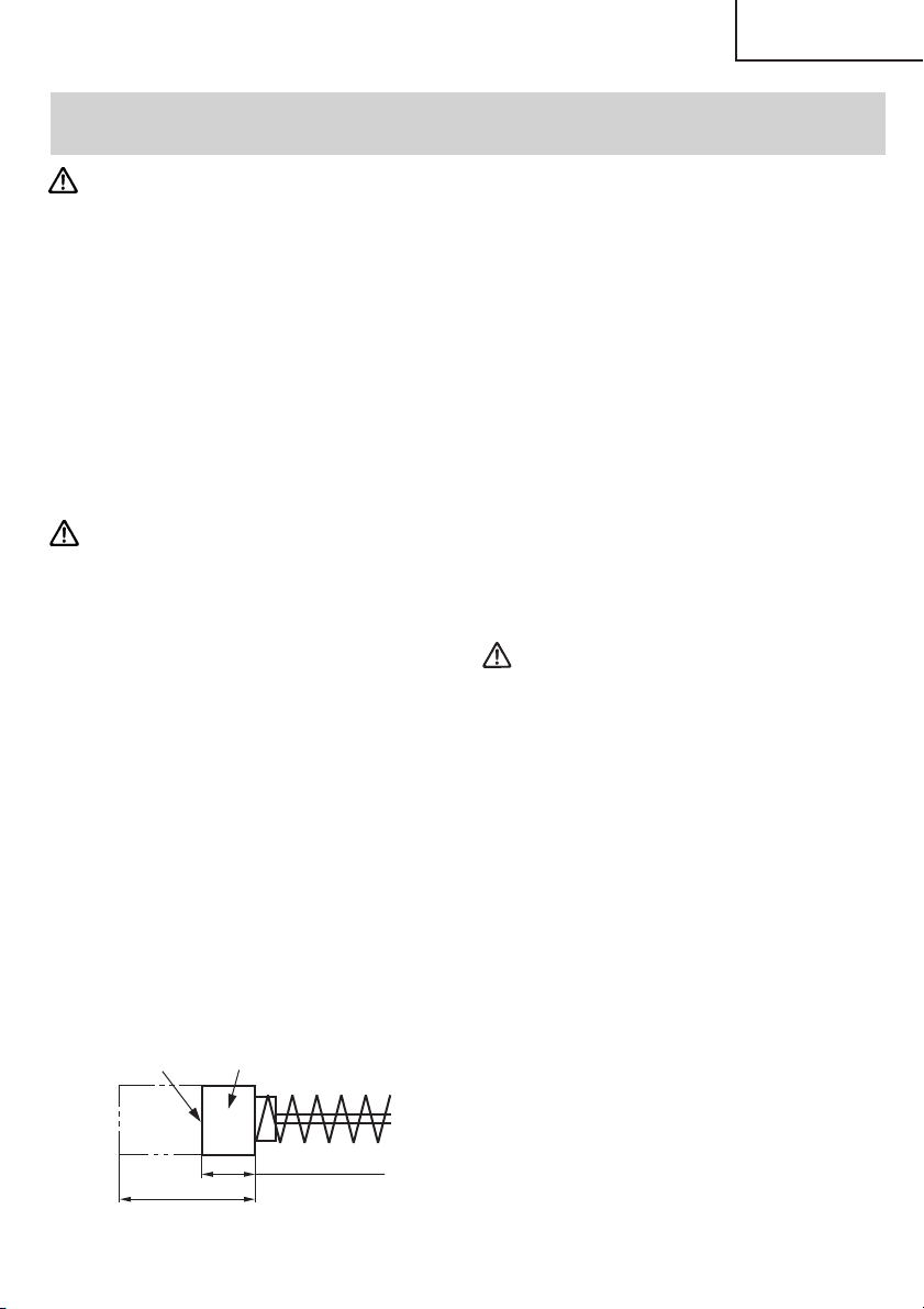
English
䡬 Select a saw blade of the most
appropriate length. Ideally, the length
protruding from the base of the saw
blade after subtracting the stroke
should be larger than the material (see
Fig. 18 and Fig. 19).
Flange of front cover
Front cover
Stroke
Fig. 18
Stroke
Fig. 21
䡬 To maximize cutting efficiency for the
materials you are using and working
conditions, adjust the speed of the saw
blade and the switching to swing cutting.
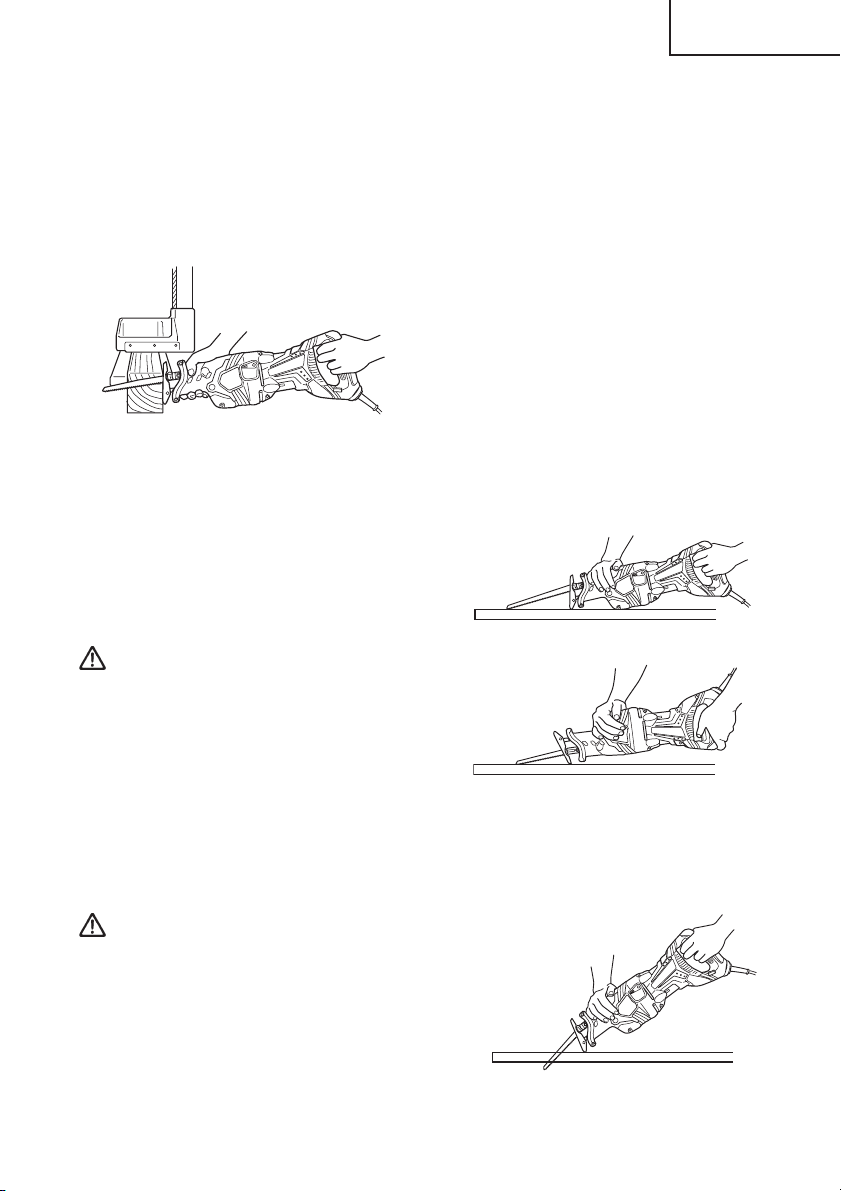
1. Cutting metallic materials
CAUTION:
䡬 Press the base firmly against the
workpiece.
䡬 Never apply any unreasonable force to
the saw blade when cutting. Doing so
can easily break the blade.
(1) Fasten a workpiece firmly before
operation. (Fig.22)
Fig. 19
If you cut a large pipe, large block of
wood, etc., that exceeds the cutting
capacity of a blade; there is a risk that
the blade may contact with the inner
wall of the pipe, wood, etc., resulting in
damage. (Fig. 20, Fig. 21)
Fig. 20
14
Fig. 22
(2) When cutting metallic materials, use
proper machine oil (turbine oil, etc.).
When not using liquid machine oil,
apply grease over the workpiece.
CAUTION:
The service life of the saw blade will
be drastically shortened if you don’t
use machine oil.
(3) Use the dial to adjust the speed of the
saw blade to suit your working
conditions and materials.
Page 15
English
(4) You can cut smoothly if you set the
change lever position to straight
cutting (Fig. 16).
2. Cutting lumber
(1) When cutting lumber, make sure that
the workpiece is fastened firmly
before beginning. (Fig. 23)
Fig. 23
(2) You can cut efficiently if the speed of
the saw blade is set to dial scale “5”.
(3) You can cut efficiently if the change
lever position is set to swing cutting
(Fig. 17). Alternatively, you can cut
cleanly if the change lever position is
set to straight cutting (Fig. 16).
CAUTION:
Never apply any unreasonable force
to the saw blade when cutting. Also
remember to press the base against
the lumber firmly.
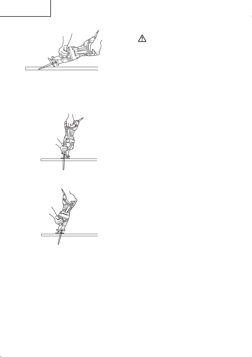
4. Plunge cutting
With this tool, you can perform pocket
cutting on plywood panels and thin
board materials. You can carry out
pocket cutting quite easily with the saw
blade installed in reverse as illustrated
in Fig. 25, Fig. 27, and Fig. 29. Use the
saw blade that is as short and thick as
possible. We recommend for this
purpose that you use BI-METAL Blade
No. 132 mentioned in Page 18. Be sure
to use caution during the cutting
operation and observe the following
procedures.
(1) Press the lower part (or the upper
part) of the base against the
material. Pull the switch trigger
while keeping the tip of the saw
blade apart from the material. (Fig.
24, Fig. 25)
Fig. 24
3. Sawing curved lines
We recommend that you use the
BIMETAL blade mentioned in Page 18
for the saw blade since it is tough and
hardly breaks.
CAUTION:
Delay the feed speed when cutting
the material into small circular arcs.
An unreasonably fast feed may
break the blade.
Fig. 25
(2) Raise the handle slowly and cut in
with the saw blade little by little. (Fig.
26, Fig. 27)
Fig. 26
15
Page 16
English
Fig. 27
(3) Hold the body firmly until the saw
blade completely cuts into the
material. (Fig. 28, Fig. 29)
Fig. 28
CAUTION:
䡬 Avoid plunge cutting for metallic
materials. This can easily damage
the blade.
䡬 Never pull the switch trigger while
the tip of the saw blade tip is
pressed against the material. If you
do so, the blade can easily be
damaged when it collides with the
material.
䡬 Make absolutely sure that you cut
slowly while holding the body
firmly. If you apply any
unreasonable force to the saw blade
during the cutting operation, the
blade can easily be damaged.
Fig. 29
16
Page 17
English
MAINTENANCE AND INSPECTION
WARNING: Be sure to switch power OFF and disconnect the plug from the
receptacle during maintenance and inspection.
1. Inspecting the blade
Continued use of a dull or damaged blade
will result in reduced cutting efficiency
and may cause overloading of the motor.
Replace the blade with a new one as soon
as excessive abrasion is noted.
2. Inspecting the mounting screws
Regularly inspect all mounting screws
and ensure that they are properly
tightened. Should any of the screws be
loosened, retighten them immediately.
WARNING: Using this reciprocating
saw with loosen screws
is extremely dangerous.
3. Maintenance of the motor
The motor unit winding is the very “heart“
of the power tool. Exercise due care to
ensure the winding does noto become
damaged and/or wet with oil or water.
4. Inspecting the carbon brushes (Fig. 30)
The Motor employs carbon brushes which
are consumable parts. When they become
worn to or near the “wear limit”, it could
result in motor trouble. When an auto-stop
carbon brush is equipped, the motor will
stop automatically. At that time, replace
both carbon brushes with new ones which
have the same carbon brush Numbers
shown in the figure. In addition, always
keep carbon brushes clean and ensure that
they slide freely within the brush holders.
No. of Carbon
Wear Limit
Brush
43
0.24" (6 mm)
NOTE: Use HITACHI carbon brush No. 43
indicated in Fig. 30.
5. Replacing carbon brushes
Disassemble the brush caps with a
slotted-head screwdriver. The carbon
brushes can then be easily removed.
6. Service and repairs
All quality power tools will eventually
require servicing or replacement of parts
because of wear from normal use. To
assure that only authorized replacement
parts will be used, all service and repairs
must be performed by a HITACHI
AUTHORIZED SERVICE CENTER, ONLY.
7. Service parts list
CAUTION:
Repair, modification and inspection of
Hitachi Power Tools must be carried out
by an Hitachi Authorized Service Center.
This Parts List will be helpful if presented
with the tool to the Hitachi Authorized
Service Center when requesting repair
or other maintenance. In the operation
and maintenance of power tools, the
safety regulations and standards
prescribed in each country must be
observed.
MODIFICATIONS:
Hitachi Power Tools are constantly being
improved and modified to incorporate
the latest technological advancements.
Accordingly, some parts may be changed
without prior notice.
0.67” (17 mm)
Fig. 30
17
Page 18

English
ACCESSORIES
WARNING: ALWAYS use Only authorized HITACHI replacement parts and
accessories. NEVER use replacement parts or accessories which are
not intended for use with this tool. Contact HITACHI if you are not sure
whether it is safe to use a particular replacement part or accessory
with your tool.
The use of any other attachment or accessory can be dangerous and
could cause injury or mechanical damage.
NOTE: Accessories are subject to change without any obligation on the part of the HITACHI.
STANDARD ACCESSORIES
(1) Blade (Code No. 725362) .....................................................................................................1
(2) Case (Code No. 321142) ...................................................................................................... 1
18
Page 19

OPTIONAL ACCESSORIES.......sold separately
English
TYPE LENGTH WIDTH TPI
6" (152 mm) 3/4" (18 mm) 6 HCS 725300 5
WOOD CUTTING 9" (228 mm) 3/4" (18 mm) 5 HCS 725301 5
12" (305 mm) 3/4" (18 mm) 6 HCS 725302 5
6" (152 mm) 3/4" (18 mm) 6 BI-METAL 725310 5
WOOD CUTTING
NAIL-EMBEDED
METAL CUTTING
ALL PURPOSE 9" (228 mm) 3/4" (18 mm) 10//14 BI-METAL 725331 5
CARBIDE GRIT 9" (228 mm) 3/4" (18 mm) GRIT — 725340 3
DEMOLITION
NEW WOOD 6" (152 mm) 3/4" (18 mm) PROG. BI-METAL 725360 5
NEW METAL 6" (152 mm) 3/4" (18 mm) PROG. BI-METAL 725361 5
NEW ALL PURPOSE 8" (203 mm) 3/4" (18 mm) PROG. BI-METAL 725362 5
6" (152 mm) 3/4" (18 mm) 6 BI-METAL 725311 5
6" (152 mm) 5/8" (16 mm) 6 BI-METAL 725312 5
9" (228 mm) 3/4" (18 mm) 6 BI-METAL 725313 5
12" (305 mm) 3/4" (18 mm) 6 BI-METAL 725314 5
6" (152 mm) 3/4" (18 mm) 10 BI-METAL 725320 5
9" (228 mm) 3/4" (18 mm) 10 BI-METAL 725321 5
6" (152 mm) 3/4" (18 mm) 14 BI-METAL 725322 5
9" (228 mm) 3/4" (18 mm) 14 BI-METAL 725323 5
6" (152 mm) 3/4" (18 mm) 18 BI-METAL 725324 5
9" (228 mm) 3/4" (18 mm) 18 BI-METAL 725326 5
6" (152 mm) 3/4" (18 mm) 24 BI-METAL 725325 5
9" (228 mm) 3/4" (18 mm) 24 BI-METAL 725327 5
6" (152 mm) 3/4" (18 mm) 10//14 BI-METAL 725330 5
12" (305 mm) 3/4" (18 mm) 10//14 BI-METAL 725332 5
9" (228 mm) 7/8" (22 mm) 6 BI-METAL 725350 3
9" (228 mm) 7/8" (22 mm) 9 BI-METAL 725351 3
MATERIAL
CODE NO.
PROG.: NEW PROGRESSIVE TOOTH HCS: HIGHSPEED CARBON STEEL
BLADES /
POUCH
NOTE: Specifications are subject to change without any obligation on the part of the
HITACHI.
19
Page 20

Français
INFORMATIONS IMPORTANTES DE SÉCURITÉ
Lire et comprendre toutes les précautions de sécurité, les avertissements et les instructions
de fonctionnement dans ce mode d’emploi avant d’utiliser ou d’entretenir cet outil motorisé.
La plupart des accidents causés lors de l’utilisation ou de l’entretien de l’outil motorisé
proviennent d’un non respect des règles ou précautions de base de sécurité. Un accident
peut la plupart du temps être évité si l’on reconnaît une situation de danger potentiel avant
qu’elle ne se produise, et en observant les procédures de sécurité appropriées.
Les précautions de base de sécurité sont mises en évidence dans la section “SECURITE” de
ce mode d’emploi et dans les sections qui contiennent les instructions de fonctionnement
et d’entretien.
Les dangers qui doivent être évités pour prévenir des blessures corporelles ou un
endommagement de la machine sont identifiés par AVERTISSEMENTS sur l’outil motorisé
et dans ce mode d’emploi.
NE JAMAIS utiliser cet outil motorisé d’une manière qui n’est pas spécifiquement
recommandée par HITACHI.
SIGNIFICATION DES MOTS D’AVERTISSEMENT
AVERTISSEMENT indique des situations potentiellement dangereuses qui, si elles sont
ignorées, pourraient entraîner la mort ou de sérieuses blessures.
PRECAUTION indique des situations dangereuses potentilles qui, si elles ne sont pas
évitées, peuvent entraîner de mineures et légères blessures ou endommager la machine.
REMARQUE met en relief des informations essentielles.
20
Page 21

SECURITE
CONSIGNES DE SÉCURITÉ GÉNÉRALES
AVERTISSEMENT: Lire toutes les instructions
Tout manquement à observer ces instructions peut engendrer
des chocs électriques, des incendies et/ou des blessures
graves.
Le terme “outil électrique” qui figure dans l'ensemble des
avertissements ci-dessous se réfère aux outils électriques
(câblé) ou aux outils à piles (sans fil).
CONSERVER CES INSTRUCTIONS
Français
1) Sécurité de l’aire de travail
a) Maintenir l'aire de travail propre et
bien éclairée.
Les endroits encombrés ou sombres
sont propices aux accidents.
b) Ne pas utiliser d'outils électriques
en présence de liquides, gaz ou
poussière inflammables, au risque
de provoquer une explosion.
Les outils électriques créent des
étincelles susceptibles d'enflammer
la poussière.
c) Ne pas laisser les enfants et les
visiteurs s'approcher de vous
lorsque vous utiliser un outil
électrique.
Les distractions peuvent faire perdre
le contrôle.
2) Sécurité électrique
a) Les prises de l'outil électrique
doivent correspondre à la prise
secteur.
Ne jamais modifier la prise.
Ne pas utiliser d'adaptateurs avec
les outils électriques mis à la masse.
Les prises non modifiées et les
prises secteurs correspondantes
réduisent les risques de choc
électrique.
b) Eviter tout contact avec les surfaces
mises à la masse telles que les
tuyaux, radiateurs, bandes et
réfrigérateurs.
Le risque de choc électrique est
accru en cas de mise à la masse du
corps.
c) Ne pas exposer les outils électriques
à la pluie ou à des conditions
humides.
Si l'eau pénètre dans l'outil, cela
augmente les risques de choc
électrique.
d) Ne pas utiliser le cordon à tort. Ne
jamais utiliser le cordon pour
transporter ou débrancher l'outil
électrique.
Maintenir le cordon loin de la
chaleur, de l'huile, des bords
pointus ou des pièces mobiles.
Les cordons endommagés ou usés
augmentent les risques de choc
électrique.
e) En cas d'utilisation d'un outil
électrique à l'extérieur, utiliser un
cordon de rallonge adapté à un
usage extérieur.
L'utilisation d'un cordon adapté à
l'usage extérieur réduit les risques
de choc électrique.
21
Page 22

Français
3) Sécurité personnelle
a) Restez alerte, regarder ce que vous
faites et usez de votre bon sens en
utilisant un outil électrique.
Ne pas utiliser d'outil électrique si
vous êtes sous l'influence de
drogues, d'alcool ou de
médicaments.
Pendant l'utilisation d'outils
électrique, un instant d'inattention
peut entraîner des blessures graves.
b) Utiliser des équipements de
sécurité. Toujours porter des verres
de protection.
L'utilisation d'équipements de
sécurité tels que les masques antipoussière, les chaussures de
sécurité anti-dérapantes, les casques
ou les protections auditives dans des
conditions appropriées réduisent les
risques de blessures.
c) Eviter les démarrages accidentels.
Veiller à ce que l'interrupteur soit en
position d'arrêt avant de brancher
l'outil.
Transporter les outils électriques
avec le doigt sur l'interrupteur ou
brancher les outils électriques avec
l'interrupteur en position de marche
peut entraîner des accidents.
d) Retirer toute clé de sécurité ou clé
avant de mettre l'outil électrique en
marche.
Laisser une clé ou une clé de sécurité
sur une partie mobile de l'outil
électrique peut engendrer des
blessures.
e) Ne pas trop se pencher. Toujours
garder une bonne assise et un bon
équilibre pendant le travail.
Cela permet un meilleur contrôle de
l'outil électrique dans des situations
imprévisibles.
f) Porter des vêtements adéquats. Ne
pas porter de vêtements amples ni
de bijoux. Maintenir les cheveux, les
vêtements et les gants loin des
pièces mobiles.
22
Les vêtements amples ou les
cheveux longs peuvent se prendre
dans les pièces mobiles.
g) En cas de dispositifs destinés au
raccordement d'installations
d'extraction et de recueil de la
poussière, veiller à ce qu'ils soient
correctement raccordés et utilisés.
L'utilisation de ces dispositifs peut
réduire les dangers associés à la
poussière.
4) Utilisation et entretien d'un outil
électrique
a) Ne pas forcer sur l'outil électrique.
Utiliser l'outil électrique adapté à
vos travaux.
Le bon outil électrique fera le travail
mieux et en toute sécurité au régime
pour lequel il a été conçu.
b) Ne pas utiliser l'outil électrique si
l'interrupteur ne le met pas en
position de marche et d'arrêt.
Tout outil ne pouvant être contrôlé
par l'interrupteur est dangereux et
doit être réparé.
c) Débrancher la prise ou retirer la
batterie avant de procéder à des
réglages, au remplacement des
accessoires ou au stockage des
outils électriques.
Ces mesures préventives de sécurité
réduisent les risques de démarrage
accidentel de l'outil électrique.
d) Stockez les outils électriques
inutilisés hors de la portée des
enfants et ne pas laisser des
personnes non familiarisées avec
l'outil ou ces instructions utiliser
l'outil électrique.
Les outils électriques sont
dangereux entre les mains
d'utilisateurs non habilités.
e) Entretenir les outils électriques.
Vérifier l'absence de mauvais
alignement ou d'arrêt,
d'endommagement de pièces ou
toute autre condition susceptible
d'affecter l'opération de l'outil.
Page 23

Français
Si l'outil est endommagé, le faire
réparer avant utilisation.
De nombreux accidents sont dus à
des outils mal entretenus.
f) Maintenir les outils coupants
aiguisés et propres.
Des outils coupants bien entretenus
avec des bords aiguisés sont moins
susceptibles de se coincer et plus
simples à contrôler.
g) Utiliser l'outil électrique, les
accessoires et les mèches de l'outil,
etc. conformément à ces
instructions et de la manière
destinée pour le type précis d'outil
électrique, en tenant compte des
conditions d'utilisation et du travail
à réaliser.
L'utilisation de l'outil électrique pour
des opérations différentes de celles
pour lesquelles il a été conçu est
dangereuse.
5) Service
a) Faire entretenir l'outil électrique par
un technicien habilité à l'aide de
pièces de rechange identiques
exclusivement.
Cela garantira le maintien de la
sécurité de l'outil électrique.
–PRECAUTION–
Pour réduire tout risque de blessure,
l’utilisateur doit lire le mode d’emploi.
REGLES DE SECURITE SPECIFIQUES ET SYMBOLES
1. Lors de l’utilisation de la scie électrique,
la tenir par les surfaces isolées de saisie
lorsqu’elle peut entrer en contact avec
des fils cachés ou son propre cordon
d’alimentation. Un contact avec un fil
“sous tension” mettra les parties
métalliques de l’outil “sous tension” et
électrocutera l’utilisateur.
2. Utiliser des serres ou un autre dispositif
de fixation pour fixer et soutenir la pièce
à une plate-forme stable. La pièce
demeure instable si on la maintient à la
main ou contre le corps et peut
provoquer une perte de contrôle.
3. TOUJOURS porter des protections
d’oreille lors de l’utilisation de l’outil
pendant de longues périodes.
Une exposition prolongée à un
son de forte intensité peut
endommager l’ouïe de
l’utilisateur.
4. NE JAMAIS toucher les parties mobiles.
NE JAMAIS placer ses mains, ses doigts
ou toute autre partie de son corps près
des parties mobiles de l’outil.
5. NE JAMAIS utiliser l’outil sans que tous
les dispositifs de sécurité ne soient en
place.
NE JAMAIS faire fonctionner cet outil
sans que tous les dispositifs et
caractéristiques de sécurité ne soient en
place et en état de fonctionnement. Si un
entretien ou une réparation nécessite le
retrait d’un dispositif ou d’une
caractéristique de sécurité, s’assurer de
bien remettre en place le dispositif ou la
caractéristique de sécurité avant de
recommencer à utiliser l’outil.
6. Utiliser l’outil correct
Ne pas forcer sur un petit outil ou
accessoire pour faire le travail d’un outil
de grande puissance. Ne pas utiliser un
outil pour un usage pour lequel il n’a pas
été prévu: par exemple, ne pas utiliser
une scie circulaire pour couper des
branches d’arbre ou des bûches.
7. NE JAMAIS utiliser un outil motorisé
pour des applications autres que celles
spécifiées.
NE JAMAIS utiliser un outil motorisé
pour des applications autres que celles
spécifiées dans le mode d’emploi.
8. Manipuler l’outil correctement
Utiliser l’outil de la façon indiquée dans
ce mode d’emploi. Ne pas laisser tomber
ou lancer l’outil. NE JAMAIS permettre
que l’outil soit utilisé par des enfants, des
personnes non familiarisées avec son
fonctionnement ou un personnel non
autorisé.
9. Maintenir toutes les vis, tous les boulons
et les couvercles fermement en place.
Maintenir toutes les vis, tous les boulons
et les couvercles fermement montés.
Vérifier leurs conditions périodiquement.
23
Page 24

Français
10. Ne pas utiliser les outils motorisés si le
revêtement de plastique ou la poignée
est fendu.
Des fentes dans le revêtement ou la
poignée peuvent entraîner une
électrocution. De tels outils ne doivent pas
être utilisés avant d’être réparé.
11. Les lames et les accessoires doivent être
fermement montés sur l’outil.
Eviter les blessures potentielles
personnelles et aux autres. Les lames, les
instruments de coupe et les accessoires
qui ont été montés sur l’outil doivent être
fixés et serrés fermement.
12. Garder propres les évents d’air du moteur
Les évents d’air du moteur doivent être
maintenus propres de façon que l’air
puisse circuler librement tout le temps.
Vérifier les accumulations de poussière
fréquemment.
13. Utiliser l’outil motorisé à la tension
nominale.
Utiliser l’outil motorisé à la tension
spécifiée sur sa plaque signalétique.
Si l’on utilise l’outil motorisé avec une tension supérieure à la tension nominale, il
en résultera une rotation anormalement
trop rapide du moteur et cela risque
d’endommager l’outil et le moteur risque
de griller.
14. NE JAMAIS utiliser un outil défectueux
ou qui fonctionne anormalement.
Si l’outil n’a pas l’air de fonctionner
normalement, fait des bruits étranges ou
sans cela paraît défectueux, arrêter de
l’utiliser immédiatement et le faire réparer
par un centre de service Hitachi autorisé.
15. NE JAMAIS laisser fonctionner l’outil sans
surveillance. Le mettre hors tension.
Ne pas abandonner l’outil avant qu’il ne
soit complètement arrêté.
16. Manipuler l’outil motorisé avec
précaution.
Si un outil motorisé tombe ou frappe un
matériau dur accidentellement, il risque
d’être déformé, fendu ou endommagé.
17. Ne pas essuyer les parties en plastique
avec du solvant.
Les solvants comme l’essence, les
diluants, la benzine, le tétrachlorure de
carbone et l’alcool peuvent endommager
et fissurer les parties en plastique. Ne pas
les essuyer avec de tels solvants.
24
Essuyer les parties en plastique avec un
chiffon doux légèrement imbibé d’une
solution d’eau savonneuse et sécher
minutieusement.
18. TOUJOURS porter des lunettes de pro
tection qui respectent les
dernières révisions du Standard
ANSI Z87.1.
19. TOUJOURS vérifier s’il y a des objets
encastrés, par exemple des fils
électriques. Le fait de toucher avec l’outil
un fil ou un câble électrique sous tension
risque de provoquer une décharge
électrique.
Avant l’utilisation, vérifier s’il y a des
objets dissimulés, par exemple des
câbles électriques, dans le mur, le
plancher ou le plafond.
20. Définitions pour les symboles utilisés sur
cet outil
V ............. volts
Hz ........... hertz
A .............ampères
n
o ............ vitesse sans charge
W ............watt
............ Construction de classe II
---/min .... rotations ou mouvements de
va-et-vient par minute
DOUBLE ISOLATION POUR UN
FONCTIONNEMENT PLUS SUR
Pour assurer un fonctionnement plus sûr de
cet outil motorisé, HITACHI a adopté une
conception à double insolation. “Double isolation” signifie que deux systèmes d’isolation
physiquement séparés ont été utilisés pour
isoler les matériaux conducteurs d’électricité
connectés à l’outil motorisé à partir du cadre
extérieur manipulé par l’utilisateur. C’est
pourquoi, le symbole “
ble insulation” (double isolation)
apparaissent sur l’outil motorisé ou sur la
plaque signalétique.
Bien que ce système n’ait pas de mise à terre
extérieure, il est quand même nécessaire de
suivre les précautions de sécurité électrique
données dans ce mode d’emploi, y-compris
de ne pas utiliser l’outil motorisé dans un
environnement humide.
” ou les mots “Dou-
Page 25

Français
Pour garder le système de double isolation
effectif, suivre ces précautions:
䡬 Seuls le centre de service après-vente
Hitachi agréé peuvent démonter et
remonter cet outil motorisé et
uniquement des pièces de rechange
HITACHI garanties d’origine doivent être
utilisées.
CONSERVER CES INSTRUCTIONS
LES METTRE A LA DISPOSITION
DES AUTRES UTILISATEURS
PROPRIETAIRES DE CET OUTIL!
䡬 Nettoyer l’extérieur de l’outil motorisé
uniquement avec un chiffon
douxplancher ou le plafond.
légèrement imbibé d’une solution
savonneuse et essuyer minutieusement.
Ne jamais utiliser des solvants, de
l’essence ou des diluants sur les parties
en plastique; sinon le plastique risquerait
de se dissoudre.
ET
ET
25
Page 26

Français
DESCRIPTION FONCTIONNELLE
REMARQUE: Les informations contenues dans ce mode d’emploi sont conçues pour assister
l’utilisateur dans une utilisation sans danger et un entretien de l’outil motorisé.
NE JAMAIS utiliser ni entreprendre une révision de l’outil sans avoir d’abord
lu et compris toutes les instructions de sécurité contenues dans ce manuel.
Certaines illustrations dans ce mode d’emploi peuvent montrer des détails
ou des accessoires différents de ceux de l’outil motorisé utilisé.
NOM DES PARTIES
Support de lame
Couvercle avant
Levier
Couvercle du balai
Interrupteur
Lame
Socle
Levier de socle
Capuchon en caoutchouc
Bouton-poussoir
Sélecteur
Fig. 1
Boîtier
Molette
Poignée
SPECIFICATIONS
Moteur Moteur série monophasé à collecteur
Source d’alimentation Secteur, 120 V 60 Hz, monophasé
Courant 13 A
Capacité Tuyau en acier doux: Diam. ext. 5" (130 mm)
Tuyau en chlorure de vinyl: Diam. ext. 5" (130 mm)
Bois: Profondeur 5" (130 mm)
Vitesse sans charge 0 – 3000/min.
Course 1-1/4" (32 mm)
Poids (sans cordon) 9.7 lbs (4.4 kg)
26
Page 27

Français
ASSEMBLAGE ET FONCTIONNEMENT
APPLICATIONS
䡬 Coupe de tuyaux en métal et en acier
inoxydable.
䡬 Coupe de différents bois de charpente.
䡬 Coupe de plaque en acier doux, de
plaque d’aluminium et de cuivre.
䡬 Coupe de résines synthétiques, comme
résine phénolique et chlorure de vinyl.
AVANT L’UTILISATION
1. Source d’alimentation
S’assurer que la source d’alimentation
qui doit être utilisée est conforme à la
source d’alimentation requise spécifiée
sur la plaque signalétique du produit.
2. Interrupteur d’alimentation
S’assurer que l’interrupteur est sur la
position OFF (arrêt). Si la fiche est
connectée sur une prise alors que
l’interrupteur est sur la position ON
(marche), l’outil motorisé démarrera
immédiatement risquant de causer de
sérieuses blessures.
3. Cordon prolongateur
Quand la zone de travail est éloignée de
la source d’alimentation, utiliser un cordon prolongateur d’épaisseur et de
capacité nominale suffisante. Le cordon
prolongateur doit être aussi court que
possible.
AVERTISSEMENT:
Tout cordon endommagé de
vra être remplacé ou réparé.
5. Vérification des conditions
d’environnement
Vérifier que l’état de l’aire de travail est
conforme aux précautions.
6. Montage de la lame
L’outil utilise un mécanisme amovible
qui permet de monter et de démonter
les lames de scie sans l’aide de clé ni
d’aucun autre outil.
(1) Allumer puis éteindre l’interrupteur-
gâchette plusieurs fois de suite de
façon que le levier puisse sortir
complètement du couvercle avant.
(Fig. 2)
Levier
ATTENTION:
Bien s’assurer que l’interrupteur est
coupé et le cordon débranché pour
éviter tout risque d’accident.
(2) Pousser le levier dans le sens de la
flèche, indiqué sur la Fig. 3, marquée
sur le levier.
Levier
Couvercle avant
Fig. 2
4. Vérifier la prise
Si la prise reçoit la fiche avec beaucoup
de jeu, elle doit être réparée. Contacter
un électricien licencié pour réaliser les
réparations nécessaires.
Si une telle prise défectueuse est utilisée,
elle peut causer une surchauffe
entraînant des dangers sérieux.
Fig. 3
(3) Insérer la lame à fond dans la petite
fente, à l’extrémité du plongeur, en
appuyant sur le levier. Il est possible
27
Page 28

Français
d’orienter la lame vers le haut ou
vers le bas. (Fig. 4, Fig. 5)
Lame
Fente de plongeur
Fig. 4
Lame
Fente de plongeur
Fig. 5
(4) Quand on relâche le levier, la force
de ressort ramène
automatiquement le levier sur la
position correcte. (Fig. 6)
Levier
Lame
Levier
Fig. 7
ATTENTION:
Lorsqu’on tire sur la lame, bien
veiller à ne tirer que sur le dos de la
lame. L’on risque de se blesser si
l’on tire sur d’autres sections.
7. Démontage de la lame
(1) Allumer puis éteindre l’interrupteur-
gâchette plusieurs fois de suite de
façon que le levier puisse sortir
complètement du couvercle avant.
Ensuite, couper l’interrupteur et
débrancher le cordon
d’alimentation. (Fig. 2)
ATTENTION:
Bien s’assurer que l’interrupteur est
coupé et le cordon débranché pour
éviter tout risque d’accident.
Fig. 6
(5) De la main, tirer deux ou trois fois
de suite sur le dos de la lame pour
vérifier qu’elle est solidement fixée.
En tirant sur la lame, l’on saura
qu’elle est montée correctement si
l’on entend un déclic et que le levier
bouge légèrement. (Fig. 7)
28
(2) Après avoir poussé le levier dans le
sens de la flèche de la Fig. 3, tourner
la lame de façon qu’elle soit orientée
vers le bas. La lame doit tomber
sous l’effet de son propre poids. Si
la lame ne tombe pas, tirer dessus
avec la main.
ATTENTION:
Ne jamais toucher la lame de scie
tout de suite après l’utilisation. Le
métal sera chaud et l’on pourrait se
brûler.
SI LA LAME EST CASSEE
Même si la lame est cassée et qu’elle
reste à l’intérieur de la petite fente du
Page 29

Français
plongeur, elle devrait tomber si l’on
pousse le levier dans le sens de la flèche
et que l’on oriente la lame vers le bas. Si
elle ne tombe pas, la sortir en procédant
comme suit.
(1) Si la section cassée de la lame sort
de la petite fente du plongeur, tirer
sur la section cassée pour sortir la
lame.
(2) Si la section cassée de la lame est
dissimulée à l’intérieur de la petite
fente du plongeur, accrocher la lame
à l’aide de l’extrémité d’une autre
lame et la sortir. (Fig. 8)
Levier
Autre lame
Fente de plongeur
Fig. 8
ENTRETIEN ET INSPECTION DE LA
MONTURE DE LAME
(1) Après l’utilisation, souffler toute
sciure, terre, sable, humidité, etc. à
l’aide d’une brosse, etc., pour
garantir le bon fonctionnement de
la monture de lame.
(2) Comme indiqué sur la Fig. 9,
graisser périodiquement tout le
pourtour du support de lame avec
du fluide de coupe, etc.
Porte-lame
Levier
REMARQUE:
Une utilisation continue de l’outil sans
nettoyer ni graisser la section où la
lame de scie est montée risque
d’entraîner un manque de nervosité
du levier en raison d’une
accumulation de sciure et de
copeaux. Dans ce cas, tirer le
capuchon de caoutchouc prévu sur le
levier dans le sens de la flèche comme
indiqué sur la Fig. 10, et retirer le
capuchon de caoutchouc de levier.
Puis nettoyer l’intérieur du support de
lame, avec un jet d’air par exemple,
et bien graisser.
Pour remonter le capuchon de
caoutchouc, l’enfoncer à fond sur le
levier. A ce moment, s’assurer qu’il
n’y a pas de jeu entre le support de
lame et le capuchon de caoutchouc,
et s’assurer que la section
d’installation de la lame de scie
fonctionne sans problème.
Levier
Capuchon en caoutchouc
Fig. 10
ATTENTION:
Ne pas utiliser de lame de scie avec
un orifice de lame usé. La lame
pourrait se détacher, ce qui
entraînerait des blessures
corporelles. (Fig. 11)
Orifice de lame
Fig. 9
Huile de machine
Lame
Fig. 11
29
Page 30

Français
8. Réglage du socle
L’outil utilise un mécanisme qui permet
de régler la position de montage du socle
sans l’aide de clé ni d’aucun autre outil.
(1) Appuyez sur le bouton-poussoir. Ce
faisant, le levier du socle sort pour
permettre de préparer le socle pour le
réglage. (Fig. 12)
Bouton-poussoir
Levier de socle
Fig. 12
(2) Pousser l’extrémité de la lame vers le
haut et pousser le socle d’avant en
arrière. (Fig. 13)
Levier de socle
Fig. 14
9. Réglage de la vitesse de va-et-vient
de la lame
L’outil possède un circuit de commande
électronique qui permet de régler la
vitesse variable de la lame soit en tirant
sur la gâchette, soit en tournant une
molette. (Fig. 15)
Socle
Fig. 13
3) La position du socle se règle en trois
étapes. Déplacer le socle à intervalles
d’environ 15 mm, vérifier la position
où le socle s’accroche, et enfoncer le
levier du socle avec les doigts. Le
socle est solidement fixé lorsqu’un
déclic se fait entendre. (Fig. 14)
30
Gâchette
Molette
(1) Si l’on appuie encore davantage sur
la gâchette, la vitesse de la lame
accélère. Commencer par couper à
vitesse lente pour garantir la précision
de la position de coupe. Une fois que
l’on a obtenu une profondeur de coupe
suffisante, augmenter la vitesse de
coupe.
(2) Sur l’échelle de la molette, “5”
représente la vitesse maximum et “1”
la vitesse minimum. La vitesse rapide
conviendra généralement pour les
matériaux tendres comme le bois, et
la vitesse lente pour les matériaux
durs comme le métal. Il est
Graduation
Fig. 15
Page 31

Français
recommandé de se reporter au guide
de référence suivant pour sélectionner
la vitesse en fonction du matériau à
couper.
Exemple de matériau Repère d’échelle
à couper recommandé
Tubes en acier doux /
tubes en fonte / 2 – 4
Angles en L en acier
Bois / bois avec clous
enfoncés
Acier inoxydable 1 – 3
Aluminium / laiton/cuivre 2 – 4
Plaques de plâtre 4 – 5
Plastique / plaques de fibres 1 – 3
5
ATTENTION:
䡬 Lors d’une coupe à vitesse lente (échelle
de 1 – 2), ne jamais couper de plaque de
bois de plus de 25/64" (10 mm)
d’épaisseur ni de tôle d’acier doux de
plus de 5/64" (2 mm) d’épaisseur. La
charge du moteur pourrait entraîner une
surchauffe et des dommages.
䡬 Bien que l’outil utilise un moteur puissant,
une utilisation prolongée à vitesse lente
augmentera excessivement la charge et
risque d’entraîner une surchauffe. Régler
correctement la lame de façon à obtenir
une opération de coupe régulière et
souple, et éviter les utilisations
capricieuses, comme les arrêts brusques
pendant la coupe.
10.
Réglage de la coupe oscillante
Il est possible de sélectionner deux
systèmes de coupe avec l’outil. Le premier
est la coupe droite, dans laquelle la lame
se déplace de façon linéaire, et le second
est la coupe oscillante, dans laquelle la
lame se balance comme un pendule. (Fig.
16, Fig. 17)
(1) Coupe droite
La coupe droite s’effectue en réglant
le sélecteur dans le sens de la largeur.
Normalement, sélectionner la coupe
droite pour couper des matériaux
durs, comme le métal, etc. (Fig. 16)
Coupe droite
Sélecteur
Fig. 16
(2) Coupe oscillante
Pour effectuer une coupe oscillante,
déplacer le sélecteur dans le sens de
la longueur. Normalement,
sélectionner la coupe oscillante pour
couper des matériaux tendres,
comme le bois, etc.
La coupe oscillante est efficace parce
que la lame pénètre de force dans le
matériau. (Fig. 17)
Sélecteur
Coupe oscillante
Fig. 17
ATTENTION:
䡬 Même avec des matériaux tendres,
effectuer une coupe droite si l’on veut
obtenir une courbe ou des coupes
nettes.
䡬 La poussière et la saleté accumulées
sur la section du sélecteur risquent
de détériorer les performances de
sélection. Nettoyer périodiquement
la section du sélecteur.
䡬 Lors d’une coupe oscillante, utiliser
une lame de scie droite, Si la lame de
scie est recourbée, elle peut se briser
ou l’outil peut être endomagé.
31
Page 32

Français
COMMENT UTILISER LA SCIE
ALTERNATIVE
ATTENTION:
䡬 Eviter de le transporter branché dans une
prise avec le doigt sur l’interrupteur. Un
démarrage brusque pourrait entraîner des
blessures inattendues.
䡬 Veiller à ce que la sciure, la terre, l’humidité,
etc. ne pénètrent pas à l’intérieur de l’outil
par la section du plongeur pendant le
fonctionnement. Si ce genre de matériaux
se sont accumulés la section du plongeur,
toujours nettoyer avant l’utilisation.
䡬 Ne pas retirer le couvercle avant (voir la Fig.
2).
Pour faire fonctionner l'outile, tenir
femement le couvercle avant.
Mais, pour éviter des blessures, ne pas
étendre la main ou les doigts au-delà du
rebord (vior Fig. 18) du couvercle avant.
䡬 Pendant l’utilisation, appuyer le socle contre
le matériau pour couper.
Les vibrations risquent d’endommager la
lame si le socle n’est pas appuyé fermement
contre la pièce.
Par ailleurs, l’extrémité de la lame peut
entrer en contact avec la paroi interne du
tube, ce qui risque d’endommager la lame.
䡬 Sélectionner une lame de la longueur
appropriée. Idéalement, la longueur qui
ressort du socle de la lame après
soustraction de la distance de course doit
être plus grande que le matériau (voir Fig.
18 et Fig. 19).
Rebord du couvercle avant
Couvercle avant
Course
Course
Fig. 19
Si l’on coupe un gros tuyau ou une pièce de
bois volumineuse qui dépassent la capacité
de coupe de la lame, la lame risque d’entrer
en contact avec la paroi interne du tube ou
avec le bois, etc., ce qui provoquera des
dommages. (Fig. 20, Fig. 21)
Fig. 20
Fig. 21
䡬 Pour obtenir le rendement de coupe maximal
pour le matériau et les conditions de travail,
régler la vitesse de la lame et passer
éventuellement à la coupe oscillante.
1. Coupe de métaux
ATTENTION:
䡬 Appuyer le socle fermement contre
Fig. 18
32
la pièce.
Page 33

Français
䡬 Ne jamais appuyer trop fort sur la
lame pendant la coupe. Cela pourrait
facilement casser la lame.
(1) Fixer solidement la pièce avant de
procéder. (Fig. 22)
Fig. 22
(2) Pour la coupe de métaux, utiliser de
l’huile de machine appropriée (huile
de turbine, etc.). Si l’on n’utilise pas
d’huile de machine liquide, appliquer
de la graisse sur toute la surface de
la pièce.
ATTENTION:
La durée de service de la lame
diminuera considérablement si l’on
n’utilise pas d’huile de machine.
(3) Utiliser la molette pour régler la vitesse
de la lame en fonction des conditions
de travail et du matériau.
(4) La coupe s’effectuera en toute facilité
si l’on règle le sélecteur sur la position
de coupe droite (Fig. 16).
2. Coupe de bois
(1) Lors de la coupe de bois, s’assurer que
la pièce est solidement fixée avant de
commencer. (Fig. 23)
Fig. 23
2) Le rendement de coupe sera efficace
si l’on règle la vitesse de la lame sur le
chiffre “5” de l’échelle de la molette
(3) Le rendement de coupe sera efficace
si l’on règle le sélecteur sur la position
de coupe oscillante (Fig. 17). Ou bien,
l’on obtiendra des coupes nettes en
réglant le sélecteur sur la position de
coupe droite (Fig. 16).
ATTENTION:
Ne jamais appuyer trop fort sur la
lame pendant la coupe. Par ailleurs,
bien penser à appuyer le socle
solidement contre la pièce.
3. Sciage de lignes courbes
Il est recommandé d’utiliser la lame
BIMETAL mentionnée au page 35 car
elle est solide et qu’elle se casse
rarement.
ATTENTION:
Ralentir la vitesse d’avance pour
couper le matériau en petits arcs
circulaires. Une vitesse excessive
risque de casser la lame.
4. Attaque en plein bois
Avec cet outil, il est possible d’effectuer
des coupes de poche dans des
panneaux de contreplaqué et des
panneaux de bois mince. La coupe de
poche s’effectue en toute facilité avec la
lame installée à l’envers, comme
indiqué aux Fig. 25, 27 et 29. Utiliser une
lame aussi courte et épaisse que
possible. Il est recommandé d’utiliser la
lame BIMETAL No.132 mentionnée dans
la page 35. Procéder avec précaution
pour effectuer la coupe de poche et
observer les procédures suivantes.
(1) Appuyez la partie inférieure (ou la
partie supérieure) du socle contre le
matériau. Tirer sur la gâchette tout
en maintenant l’extrémité de la lame
éloignée du matériau. (Fig. 24, Fig.
25)
33
Page 34

Français
Fig. 24
Fig. 25
(2) Relever lentement la poignée et
couper petit à petit avec la lame de
scie. (Fig. 26, Fig. 27)
Fig. 26
Fig. 27
(3) Tenir le corps de l’outil fermement
jusqu’à ce que la lame aient
complètement coupé le matériau.
(Fig. 28, Fig. 29)
Fig. 28
Fig. 29
ATTENTION:
䡬 Eviter les attaques en plein
matériau avec les métaux. Cela
endommagerait facilement la lame.
䡬 Ne jamais tirer sur la gâchette alors
que l’extrémité de la lame est
appuyée contre le matériau. La lame
s’endommagera facilement si elle
entre en contact avec le matériau.
䡬 Veiller impérativement à couper le
matériau lentement et en tenant le
corps de l’outil fermement. Si l’on
appuie trop fort sur la lame pendant
l’opération de coupe, la lame risque
de s’endommager facilement.
34
Page 35

Français
ENTRETIEN ET INSPECTION
AVERTISSEMENT:
S’assurer de mettre l’interrupteur d’alimentation sur la position OFF et de déconnecter
la fiche de la prise secteur avant l’entretien et l’inspection de la meuleuse.
1. Contrôle de la lame
L’utilisation continue d’une lame
émoussée ou endommagée pourrait
réduire l’efficacité de coupe et provoquer
une surchage du moteur. Remplacer la
lame par une nouvelle dès que des traces
d’abrasion apparaissent.
2. Inspection des vis de montage
Inspecter régulièrement toutes les vis de
montage et s’assurer qu’elles sont
correctement serrées. Si l’une des vis
était desserrée, la resserrer
immédiatement.
AVERTISSEMENT:
Utiliser la scie alternative avec des vis
desserrées est extrêmement dangereux.
3. Entretien du moteur:
Le bobinage de l’ensemble moteur est le
“coeur” même de l’outil électro-portatif.
Veiller soigneusement à ce que ce
bobinage ne soit pas endommagé et/ou
mouillé par de l’huile ou de l’eau.
4. Contrôle des balais en carbone (Fig.
30)
Le moteur utilise des balais en carbone
qui sont des pièces qui s’usent. Quand ils
sont usés ou près de la “limite d’usure”,
il pourra en résulter un mauvais
fonctionnement du moteur.
Quand le moteur est équipé d’un balai en
carbone à arrêt automatique, il s’arrêtera
automatiquement. Remplacez alor les
balais en carbone par des nouveaux et
ayant les mêmes numéros que ceux
montré sur la figure. En outre, toujours
tenir les balais propres et veiller à ce qu’ils
coulissent librement dans les supports.
Limite
d’usure
0,67" (17 mm)
REMARQUE: Utiliser le balai en carbone
No. du balai
en carbone
43
0,24" (6 mm)
Fig. 30
HITACHI No. 43 indiqué sur
la Fig. 30.
5. Remplacement d’un balai en
carbone
Retirer le couvercle du balai avec un
tournevis plat. Le balai en carbone peut
être alors facilement retiré.
6. Service apres-vente et reparations
Tous les outils motorisés de qualité
auront éventuellement besoin d’une
réparation ou du remplacement d’une
pièce à cause de l’usure normale de
l’outil. Pour assurer que seules des
pièces de rechange autorisées seront
utilisées, tous les entretiens et les
réparations doivent être effectués
uniquement par UN CENTRE DE
SERVICE HITACHI AUTORISE.
7. Liste des pièces de rechange
PRECAUTION:
La réparation, la modification et
l’inspection des outils électriques
Hitachi doivent être effectuées par un
35
Page 36

Français
Centre de service agréé Hitachi.
Cette liste des pièces présentée avec
l’outil au Centre de service agréé Hitachi
est utile lors d’une demande de
réparation ou d’entretien. Il faut
observer la réglementation et les
normes de sécurité de chaque pays lors
de l’utilisation et de l’entretien des
outils électriques.
MODIFICATIONS :
Les outils électriques Hitachi font l’objet
d’améliorations et de modifications
constantes afin d’y incorporer les toutes
dernières technologies.
Par conséquent, certaines pièces
peuvent changer sans préavis.
ACCESSOIRES
AVERTISSEMENT: TOUJOURS utiliser UNIQUEMENT des pièces de rechange et
des accessoires HITACHI. Ne jamais utiliser de pièce de
rechange ou d’accessoires qui ne sont pas prévus pour être
utilisé avec cet outil. En cas de doute, contacter HITACHI pour
savoir si une pièce de rechange ou un accessoire particulier
peuvent être utilisés en toute sécurité avec votre outil.
L’utilisation de tout autre attachement ou accessoire peut
être dangereux et peut causer des blessures ou des dommages
mécaniques.
REMARQUE: Les accessoires sont sujets à changement sans obligation de la part de
HITACHI.
ACCESSOIRES STANDARD
(1) Lame (No.de code 725362) ................................................................................................ 1
(2) Boîter (No. de code 321142) .............................................................................................. 1
36
Page 37

ACCESSOIRES SUR OPTION......vendus séparément
Français
TYPE LONGUEUR LARGEUR TPI MATÉRIAU
COUPE DE BOIS 9" (228 mm) 3/4" (18 mm) 5 HCS 725301 5
COUPE DE BOIS AVEC
CLOUS ENFONCÉS
COUPE DE MÉTAUX
TOUS USAGES 9" (228 mm) 3/4" (18 mm) 10//14 bi-métal 725331 5
GRENAILLE AU CARBURE
DÉMOLITION
BOIS NEUF 6" (152 mm) 3/4" (18 mm) PROG. bi-métal 725360 5
MÉTAL NEUF 6" (152 mm) 3/4" (18 mm) PROG. bi-métal 725361 5
TOUS USAGES, NEUFS
6" (152 mm) 3/4" (18 mm) 6 HCS 725300 5
12" (305 mm) 3/4" (18 mm) 6 HCS 725302 5
6" (152 mm) 3/4" (18 mm) 6 bi-métal 725310 5
6" (152 mm) 3/4" (18 mm) 6 bi-métal 725311 5
6" (152 mm) 5/8" (16 mm) 6 bi-métal 725312 5
9" (228 mm) 3/4" (18 mm) 6 bi-métal 725313 5
12" (305 mm) 3/4" (18 mm) 6 bi-métal 725314 5
6" (152 mm) 3/4" (18 mm) 10 bi-métal 725320 5
9" (228 mm) 3/4" (18 mm) 10 bi-métal 725321 5
6" (152 mm) 3/4" (18 mm) 14 bi-métal 725322 5
9" (228 mm) 3/4" (18 mm) 14 bi-métal 725323 5
6" (152 mm) 3/4" (18 mm) 18 bi-métal 725324 5
9" (228 mm) 3/4" (18 mm) 18 bi-métal 725326 5
6" (152 mm) 3/4" (18 mm) 24 bi-métal 725325 5
9" (228 mm) 3/4" (18 mm) 24 bi-métal 725327 5
6" (152 mm) 3/4" (18 mm) 10//14 bi-métal 725330 5
12" (305 mm) 3/4" (18 mm) 10//14 bi-métal 725332 5
9" (228 mm) 3/4" (18 mm) GRIT — 725340 3
9" (228 mm) 7/8" (22 mm) 6 bi-métal 725350 3
9" (228 mm) 7/8" (22 mm) 9 bi-métal 725351 3
8" (203 mm) 3/4" (18 mm) PROG. bi-métal 725362 5
NO. DE LAMES/
CODE POCHE
PROG.: NOUVELLE DENT PROGRESSIVE HCS: ACIER AU CARBONE RAPIDE
REMARQUE: Les spécifications sont sujettes à modification sans aucune obligation de la
part de HITACHI.
37
Page 38

Español
INFORMACIÓN IMPORTANTE SOBRE SEGURIDAD
Antes de utilizar o de realizar cualquier trabajo de mantenimiento de esta herramienta
eléctrica, lea y comprenda todas las precauciones de seguridad, advertencias e instrucciones
de funcionamiento de este Manual de instrucciones.
La mayoría de los accidentes producidos en la operación y el mantenimiento de una
herramienta eléctrica se deben a la falta de observación de las normas o precauciones de
seguridad. Los accidentes normalmente podrán evitarse reconociendo una situación
potencialmente peligrosa a tiempo y siguiendo los procedimientos de seguridad apropiados.
Las precauciones básicas de seguridad se describen en la sección “SEGURIDAD” de este
Manual de instrucciones y en las secciones que contienen las instrucciones de operación y
mantenimiento.
Para evitar lesiones o el daño de la herramienta eléctrica, los riesgos están identificados
con ADVERTENCIAS en dicha herramienta y en este Manual de instrucciones.
No utilice NUNCA esta herramienta eléctrica de ninguna forma que no esté específicamente
recomendada por HITACHI.
SIGNIFICADO DE LAS PALABRAS DE SEÑALIZACIÓN
ADVERTENCIA indica situaciones potencialmente peligrosas que, si se ignoran, pueden
resultar en la muerte o en lesiones de gravedad.
PRECAUCIÓN indica situaciones potencialmente peligrosas que, de no evitarse, pueden
resultar en lesiones menores o moderadas, o causar daños en la herramienta eléctrica.
NOTA acentúa información esencial.
38
Page 39

SEGURIDAD
NORMAS GENERALES DE SEGURIDAD
ADVERTENCIA: Lea todas las instrucciones
Si no se siguen las instrucciones de abajo podría producirse una
descarga eléctrica, un incendio y/o daños graves.
El término “herramienta eléctrica” en todas las advertencias
indicadas a continuación hace referencia a la herramienta eléctrica
que funciona con la red de suministro (con cable) o a la
herramienta eléctrica que funciona con pilas (sin cable).
CONSERVE ESTAS INSTRUCCIONES
1) Seguridad en el área de trabajo
a) Mantenga la zona de trabajo limpia
y bien iluminada.
Las zonas desordenadas o oscuras
pueden provocar accidentes.
b) No utilice las herramientas
eléctricas en entornos explosivos
como, por ejemplo, en presencia de
líquidos inflamables, gases o polvo.
Las herramientas eléctricas crean
chispas que pueden hacer que el
polvo desprenda humo.
c) Mantenga a los niños y transeúntes
alejados cuando utilice una
herramienta eléctrica.
Las distracciones pueden hacer que
pierda el control.
2) Seguridad eléctrica
a) Los enchufes de las herramientas
eléctricas tienen que ser adecuados
a la toma de corriente.
No modifique el enchufe.
No utilice enchufes adaptadores
con herramientas eléctricas
conectadas a tierra.
Si no se modifican los enchufes y
se utilizan tomas de corriente
adecuadas se reducirá el riesgo de
descarga eléctrica.
b) Evite el contacto corporal con
superficies conectadas a tierra
como tuberías, radiadores y
c) No exponga las herramientas
d) No utilice el cable incorrectamente.
e) Cuando utilice una herramienta
3) Seguridad personal
a) Esté atento, preste atención a lo que
Español
frigoríficos.
Hay mayor riesgo de descarga
eléctrica si su cuerpo está en
contacto con el suelo.
eléctricas a la lluvia o a la humedad.
La entrada de agua en una
herramienta eléctrica aumentará el
riesgo de descarga eléctrica.
No utilice el cable para transportar,
tirar de la herramienta eléctrica o
desenchufarla.
Mantenga el cable alejado del calor,
del aceite, de bordes afilados o
piezas móviles.
Los cables dañados o enredados
aumentan el riesgo de descarga
eléctrica.
eléctrica al aire libre, utilice un cable
prolongador adecuado para
utilizarse al aire libre.
La utilización de un cable adecuado
para usarse al aire libre reduce el
riesgo de descarga eléctrica.
hace y utilice el sentido común
cuando utilice una herramienta
eléctrica.
39
Page 40

Español
No utilice una herramienta eléctrica
cuando esté cansado o esté bajo la
influencia de drogas, alcohol o
medicación.
La distracción momentánea cuando
utiliza herramientas eléctricas
puede dar lugar a importantes
daños personales.
b) Utilice equipo de seguridad. Utilice
siempre una protección ocular.
El equipo de seguridad como
máscara para el polvo, zapatos de
seguridad antideslizantes, casco o
protección para oídos utilizado para
condiciones adecuadas reducirá los
daños personales.
c) Evite un inicio accidental.
Asegúrese de que el interruptor
está en “off” antes de enchufarlo.
El transporte de herramientas
eléctricas con el dedo en el
interruptor o el enchufe de
herramientas eléctricas con el
interruptor encendido puede
provocar accidentes.
d) Retire las llaves de ajuste antes de
encender la herramienta eléctrica.
Si se deja una llave en una pieza
giratoria de la herramienta eléctrica
podrían producirse daños
personales.
e) No se extralimite. Mantenga un
equilibrio adecuado en todo
momento.
Esto permite un mayor control de
la herramienta eléctrica en
situaciones inesperadas.
f) Vístase adecuadamente. No lleve
prendas sueltas o joyas. Mantenga
el pelo, la ropa y los guantes
alejados de las piezas móviles.
La ropa suelta, las joyas y el pelo
largo pueden pillarse en las piezas
móviles.
g) Si se proporcionan dispositivos
para la conexión de extracción de
polvo e instalaciones de recogida,
asegúrese de que están conectados
40
y se utilizan adecuadamente.
La utilización de estos dispositivos
puede reducir los riesgos
relacionados con el polvo.
4) Utilización y mantenimiento de las
herramientas eléctricas
a) No fuerce la herramienta eléctrica.
Utilice la herramienta eléctrica
correcta para su aplicación.
La herramienta eléctrica correcta
trabajará mejor y de forma más
segura si se utiliza a la velocidad
para la que fue diseñada.
b) No utilice la herramienta eléctrica
si el interruptor no la enciende y
apaga.
Las herramientas eléctricas que no
pueden controlarse con el
interruptor son peligrosas y deben
repararse.
c) Antes de hacer ajustes, cambiar
accesorios o almacenar las
herramientas eléctricas, desconecte
el enchufe de la fuente eléctrica y/o
las baterías de la herramienta.
Estas medidas de seguridad
preventivas reducen el riesgo de
que la herramienta eléctrica se
ponga en marcha accidentalmente.
d) Guarde las herramientas eléctricas
que no se utilicen para que no las
cojan los niños y no permita que
utilicen las herramientas eléctricas
personas no familiarizadas con las
mismas o con estas instrucciones.
Las herramientas eléctricas son
peligrosas si son utilizadas por
usuarios sin formación.
e) Mantenimiento de las herramientas
eléctricas. Compruebe si las piezas
móviles están mal alineadas o
unidas, si hay alguna pieza rota u
otra condición que pudiera afectar
al funcionamiento de las
herramientas eléctricas.
Si la herramienta eléctrica está
dañada, llévela a reparar antes de
utilizarla.
Page 41

Español
Se producen muchos accidentes por
no realizar un mantenimiento
correcto de las herramientas
eléctricas.
f) Mantenga las herramientas de corte
afiladas y limpias.
Las herramientas de corte
correctamente mantenidas con los
bordes de corte afilados son más
fáciles de controlar.
g) Utilice la herramienta eléctrica, los
accesorios y las brocas de la
herramienta, etc., de acuerdo con
estas instrucciones y de la manera
adecuada para el tipo de
herramienta eléctrica, teniendo en
cuenta las condiciones laborales y
el trabajo que se va a realizar.
La utilización de la herramienta
eléctrica para operaciones
diferentes a pretendidas podría dar
lugar a una situación peligrosa.
5) Revisión
a) Lleve su herramienta a que la revise
un experto cualificado que utilice
sólo piezas de repuesto idénticas.
Esto garantizará el mantenimiento
de la seguridad de la herramienta
eléctrica.
–ADVERTENCIA–
Para disminuir el riesgo de lesiones, el
usuario debe leer el manual de
instrucciones.
NORMAS Y SÍMBOLOS
ESPECÍFICOS DE SEGURIDAD
1. Sujete las herramientas por las superficies de empuñadura aisladas cuando
realice una operación en la que la
herramienta de corte pueda entrar en
contacto con cables ocultos o con su
propio cable de alimentación. El contacto
con un conductor “activo” “activará” las
partes metálicas de la herramienta y el
operador recibirá una descarga eléctrica.
2. Utilice las abrazaderas u otro método
práctico para asegurar y sujetar la pieza
a una plataforma estable. Si sujeta la
pieza con la mano o contra el cuerpo,
éste queda inestable y se puede erder el
control sobre el mismo.
3. SIEMPRE utilice protectores auditivos
cuando tenga que utilizar la herramienta
durante mucho tiempo.
La exposición prolongada a
ruido de gran intensidad
puede causar la sordera.
4. NO toque NUNCA las piezas móviles.
NO coloque NUNCA sus manos, dedos,
ni demás partes del cuerpo cerca de las
piezas móviles de la herramienta.
5. NO utilice NUNCA la herramienta sin los
protectores colocados en su lugar.
NO utilice NUNCA esta herramienta sin
los protectores de seguridad
correctamente instalados. Si el trabajo de
mantenimiento o de reparación requiere
el desmontaje de un protector de
seguridad, cerciórese de volver a
instalarlo antes de utilizar la herramienta.
6. Utilice la herramienta correcta.
No fuerce herramientas ni accesorios
pequeños para realizar un trabajo
pesado.
No utilice las herramientas para fines no
proyectados, por ejemplo, no utilice esta
amoladora angular para cortar madera.
7. NO utilice NUNCA una herramienta
eléctrica para aplicaciones que no sean
las especificadas.
NO utilice NUNCA una herramienta
eléctrica para aplicaciones no
especificadas en este Manual de
instrucciones.
8. Maneje correctamente la herramienta.
Maneje la herramienta de acuerdo con
las instrucciones ofrecidas aquí. No deje
caer ni tire la herramienta. NO permita
NUNCA que los niños ni otras personas
no autorizadas ni familiarizadas con la
operación de la herramienta utilicen ésta.
9. Mantenga todos los tornillos, pernos, y
cubiertas firmemente fijados en su lugar.
Mantenga todos los tornillos, pernos, y
cubiertas firmemente montados.
Compruebe periódicamente su
condición.
41
Page 42

Español
10. No utilice herramientas eléctricas si la
carcasa o la empuñadura de plástico está
rajada.
Las rajas en la carcasa o en la
empuñadura de plástico pueden
conducir a descargas eléctricas. Tales
herramientas no deberán utilizarse
mientras no se hayan reparado.
11. Las cuchillas y los accesorios deberán
montarse con seguridad en la
herramienta.
Evite lesiones personales y de otras personas. Las cuchillas, los accesorios de
corte, y demás accesorios montados en
la herramienta deberán fijarse con
seguridad.
12. Mantenga limpio el conducto de
ventilación del motor.
El conducto de ventilación del motor
limpio para que el aire pueda circular
libremente en todo momento.
Compruebe frecuentemente y limpie el
polvo acumulado.
13. Utilice las herramientas eléctricas con la
tensión de alimentación nominal.
Utilice las herramientas eléctricas con las
tensiones indicadas en sus placas de
características.
La utilización e una herramienta eléctrica
con una tensión superior a la nominal
podría resultar en revoluciones
anormalmente altas del motor, en el
daño de la herramienta, y en la
quemadura del motor.
14. NO utilice NUNCA una herramienta
defectuosa o que funcione
anormalmente.
Si la herramienta parece que funciona
anormalmente, produciendo ruidos
extraños, etc., deje inmediatamente de
utilizarla y solicite su arreglo a un centro
de reparaciones autorizado por Hitachi.
15. NO deje NUNCA la herramienta en
funcionamiento desatendida.
Desconecte su alimentación.
No deje sola la herramientas hasta
mientras no se haya parado
completamente.
16. Maneje con cuidado las herramientas
eléctricas.
Si una herramienta eléctrica se ha caído
o ha chocado inadvertidamente contra
materiales duros, es posible que se haya
deformado, rajado, o dañado.
17. No limpie las partes de plástico con
disolvente.
Los disolventes, como gasolina, diluidor
de pintura, bencina, tetracloruro de
carbono, y alcohol pueden dañar o rajar
las partes de plástico. No las limpie con
tales disolventes.
Limpie las partes de plástico con un paño
suave ligeramente humedecido en agua
jabonosa y después séquelas bien.
18. SIEMPRE utilice gafas protectoras qu
cumplan con los requerimientos
de la última revisión de la norma
ANSI Z87.1.
19. SIEMPRE tenga cuidado con los objetos
que puedan estar enterrados o
emparedados, tales como los cables
subterráneos.
Si tocase un circuito activo o un cable
eléctv˝ o con esta herramienta, podría
recibir una descarga eléctrica.
Antes del uso, confirme que no haya
objetos ocultos, como los cables
eléctricos enterrados en la pared, el piso
o el techo.
20. Definiciones para los símbolos utilizados
en esta herramienta
V ............. voltios
Hz ........... hertzios
A .............amperios
n
o ............ velocidad sin carga
W ............vatios
............ Construcción de clase II
---/min .... revoluciones o reciprocación
por minuto
AISLAMIENTO DOBLE PARA OFRECER
UNA OPERACIÓN MÁS SEGURA
Para garantizar una operación más segura
de esta herramienta eléctrica, HITACHI ha
adoptado un diseño de aislamiento doble.
“Aislamiento doble” significa que se han
utilizado dos sistemas de aislamiento
físicamente separados para aislar los
materiales eléctricamente conductores
conectados a la fuente de alimentación del
bastidor exterior manejado por el operador.
42
Page 43

Español
Por lo tanto, en la herramienta eléctrica o
en su placa de características aparecen el
símbolo “ ” o las palabras “Double insulation” (aislamiento doble).
Aunque este sistema no posee puesta a
tierra externa, usted deberá seguir las
precauciones sobre seguridad eléctrica
ofrecidas en este Manual de instrucciones,
incluyendo la no utilización de la
herramienta eléctrica en ambientes
húmedos.
Para mantener efectivo el sistema de
aislamiento doble, tenga en cuenta las
precauciones siguientes:
¡GUARDE ESTAS
INSTRUCCIONES
PÓNGALAS A DISPOSICIÓN DE
OTROS USUARIOS
䡬 Esta herramienta eléctrica solamente
deberá desensamblar y ensamblarla por
un Centro de Servicio Autorizado de
Hitachi, y solamente deberán utilizarse
con ella piezas de reemplazo genuinas
de HITACHI.
䡬 Limpie el exterior de la herramienta
eléctrica solamente con un paño suave
humedecido en agua jabonosa, y
después séquela bien.
No utilice disolventes, gasolina, ni
diluidor de pintura para limpiar las partes
de plástico, ya que podría disolverlas.
Y
Y
PROPIETARIOS DE ESTA
HERRAMIENTA!
43
Page 44

Español
DESCRIPCIÓN FUNCIONAL
NOTA: La información contenida en este Manual de instrucciones ha sido diseñada para
ayudarle a utilizar con seguridad y mantener esta herramienta eléctrica.
NUNCA haga funcionar ni efectúe el mantenimiento de la herramienta antes de
leer y comprender todas las instrucciones de seguridad contenidas en este manual.
Algunas ilustraciones de este Manual de Instrucciones pueden mostrar detalles o
accesorios diferentes a los de la propia herramienta eléctrica.
NOMENCLATURA
Portacuchilla
Palanca
Hoja
Base
Tapa de goma
Cubierta delantera
Botón pulsador
Palanca de base
Tapa del portaescobilla
Interruptor
Empuñadura
Carcasa
Palanca de cambio
Cuadrante
Fig. 1
ESPECIFICACIONES
Motor Motor conmutador en serie monofásico
Fuente de alimentación 120 V CA, 60 Hz, monofásica
Corriente 13 A
Capacidad Tubo de acero pobre en carbono: D.E. 5" (130 mm)
Tubo de cloruro de vinilo: D.E. 5" (130 mm)
Madera:
Velocidad de marcha en vacío 0 – 3000/min.
Carrera 1-1/4" (32 mm)
Peso (sin cable) 9.7 lbs (4.4 kg)ñ
Profundidad 5" (130 mm)
44
Page 45

MONTAJE Y OPERACIÓN
Español
APLICACIONES
䡬 Corte de tubos metálicos y de acero
inoxidable.
䡬 Cortes de diversas maderas útiles.
䡬 Corte de placa de acero pobre en
carbono, de aluminio y de cobre.
䡬 Corte de resina sintética, tal como resina
de fenol y cloruro de vinilo.
ANTES DE LA OPERACIÓN
1. Fuente de alimentación
Cerciórese de que la fuente de
alimentación que vaya a utilizar cumpla
los requisitos indicados en la placa de
características del producto.
2. Interruptor de alimentación
Cerciórese de que el interruptor de
alimentación esté en la posición OFF. Si
enchufase el cable de alimentación en un
tomacorriente de la red con el interruptor
en ON, la herramienta eléctrica
comenzaría a funcionar inmediatamente,
lo que podría provocar lesiones serias.
3. Cable prolongador
Cuando el área de trabajo esté alejada
de la fuente de alimentación, utilice un
cable prolongador de suficiente grosor
y con la capacidad nominal. El cable
prolongador deberá mantenerse lo más
corto posible.
ADVERTENCIA:
Si un cable esta dañado
deberá reemplazar o
repararse.
4. Comprobación del tomacorriente
Si el enchufe del cable de alimentación
queda flojo en el tomacorriente, habrá
que reparar éste. Póngase en contacto
con un electricista cualificado para que
realice las reparaciones adecuadas.
Si utilizase un tomacorriente en este
estado, podría producirse
recalentamiento, lo que supondría un
riesgo serio.
5. Confirme las condiciones del medio
ambiente.
Condirme que el lugar de trabajo esté en
las condiciones apropiadas de acuerdo
con las precauciones descritas.
6. Montaje de la hoja
Esta unidad emplea un mecanismo
desmontable que permite montar y
desmontar las hojas de sierra sin
necesidad de llave u otras herramientas.
(1) Conecte y desconecte varias veces el
gatillo interruptor de manera que la
palanca pueda salir completamente
de la cubierta delantera.
Seguidamente, desconecte el
interruptor y desenchufe el cable de
alimentación. (Fig. 2)
Palanca
PRECAUCION:
Para evitar accidentes, asegúrese de
mantener el interruptor
desconectado y el cable de
alimentación desenchufado.
(2) Empuje la palanca en la dirección de
la flecha indicada en la Fig. 3 y
marcada en la misma. Si gira el
manguito del sujetador hasta la
mitad conseguirá asegurarlo
automáticamente.
Cubierta delantera
Fig. 2
45
Page 46

Español
Palanca
Fig. 3
(3) Inserte completamente la hoja de
sierra en la hendidura pequeña de
la punta del émbolo mediante el
empuje de la palanca. Esta hoja
puede montarse tanto en dirección
ascendente como descendente. (Fig.
4, Fig. 5)
Hoja
Ranura del émbolo
Fig. 4
Hoja
Ranura del émbolo
Fig. 5
(4) Cuando suelte la palanca, la fuerza
del resorte hará que el manguito del
sujetador vuelva automáticamente
a la posición correcta. No hay
necesidad de asegurar el manguito
del sujetador en este momento. (Fig.
6)
46
Palanca
Fig. 6
(5) Con la mano, tire de la hoja de sierra
hacia atrás dos o tres veces y
verifique que la hoja esté
firmemente instalada. Si al tirar de
la hoja ésta produce un chasquido
y la palanca se mueve ligeramente,
significa que se encuentra
correctamente instalada. (Fig. 7)
Hoja
Palanca
Fig. 7
PRECAUCION:
Cuando tire de la hoja de sierra,
asegúrese de hacerlo desde atrás.
Si intenta tirar de la misma desde
alguna otra parte, podrá sufrir
lesiones.
7. Desmontaje de la hoja
(1) Conecte y desconecte varias veces
el gatillo interruptor de manera que
la palanca pueda salir
completamente de la cubierta
delantera. Seguidamente,
desconecte el interruptor y
desenchufe el cable de
alimentación. (Fig. 2)
PRECAUCION:
Para evitar accidentes, asegúrese de
mantener el interruptor
desconectado y el cable de
alimentación desenchufado.
Page 47

Español
(2) Después de haber empujado la
palanca en la dirección de la flecha
mostrada en la Fig. 3, gire la hoja
de manera que quede dirigida hacia
abajo. La hoja debe caer por su
propio peso. Si la hoja no cae,
extráigala con la mano.
PRECAUCION:
Nunca toque la hoja de sierra
inmediatamente después de
haberla utilizado. El metal estará
caliente y podrá quemarse.
CUANDO SE ROMPA LA HOJA
Aun cuando la hoja de sierra se rompa
y permanezca dentro de la pequeña
hendidura del émbolo, la misma saldrá
si empuja la palanca en la dirección de
la flecha. Por lo tanto, dirija la hoja hacia
abajo. Si no sale por sí misma,
extráigala de la siguiente manera.
(1) Si una parte de la hoja de sierra rota
sobresale de la pequeña hendidura
del émbolo, extraiga la parte
saliente y extraiga la hoja.
(2) Si la hoja de sierra rota se encuentra
oculta dentro de la pequeña
hendidura, enganche la hoja rota
utilizando la punta de otra hoja de
sierra y extráigala. (Fig. 8)
Palanca
Otra hoja
Ranura del
émbolo
Fig. 8
MANTENIMIENTO E INSPECCION DE
LA MONTURA DE LA HOJA DE SIERRA
(1) Después de utilizar la sierra, elimine
el aserrín, el polvo, la arena, la
humedad, etc. con aire o con un
cepillo, etc. para asegurarse de que
la montura de la hoja funciona
suavemente.
(2) Tal como se muestra en la Fig. 9,
lubrique periódicamente alrededor
del sujetador de la hoja con
lubricante para cuchillas.
Portacuchilla
Palanca
Aceite para máquinas
Fig. 9
NOTA:
Si utilizara la herramienta sin haber
realizado la limpieza y la lubricación
del área en que se instala la hoja de
sierra, el movimiento de la palanca
podría volverse lento debido a la
acumulación de partículas de polvo
y aserrín. En tal caso, tire de la tapa
de goma provista en la palanca en
la dirección de la flecha tal como se
muestra en la Fig. 10 y extraiga la
tapa de goma de la palanca. Luego,
limpie el interior del sujetador de la
hoja con aire, etc., y lubrique
suficientemente.
Compruebe que la tapa de goma
esté correctamente instalada y que
esté presionada firmemente sobre
la palanca. En este momento,
asegúrese de que no haya ninguna
holgura entre el sujetador de la hoja
y la tapa de goma, y compruebe que
el área de instalación de la hoja de
sierra pueda funcionar suavemente.
47
Page 48

Español
Palanca
Tapa de goma
Fig. 10
PRECAUCION:
No utilice ninguna hoja de sierra con
el orificio de la hoja gastado. De lo
contrario, la hoja podría soltarse y
provocar lesiones personales.
(Fig.11)
Orificio de la hoja
Hoja
Fig. 11
8. Ajuste de la base
Esta unidad emplea un mecanismo que
permite ajustar la posición de montaje
de la base en tres etapas, sin necesidad
de llave u otras herramientas.
(1) Presione el botón pulsador. Al hacerlo,
la palanca de base saltará hacia afuera
y la base quedará preparada para el
ajuste. (Fig. 12)
Botón pulsador
(2) Empuje la punta de la base hacia
arriba y sacuda la base hacia atrás y
adelante. (Fig. 13)
Base
Fig. 13
(3) La posición de la base puede ajustarse
en tres etapas. Mueva la base a un
intervalo de aproximadamente 15
mm, encuentre la posición en que la
base queda enganchada, y presione
hacia adentro la palanca de base con
los dedos. Al escuchar un chasquido
significa que la base ha quedado
asegurada. (Fig. 14)
Palanca de base
Fig. 14
Palanca de base
48
9. Ajuste de la velocidad alternativa de
la hoja
Esta unidad está provista de un circuito
de control electrónico incorporado que
hace posible controlar la velocidad
variable de la hoja de sierra tirando del
gatillo conmutador o bien girando un
cuadrante. (Fig. 15)
Fig. 12
Page 49

Cuadrante
Fig. 15
Interruptor
de gatillo
Graduación
Español
al motor podría producir
recalentamientos y daños.
䡬 Aunque esta unidad emplea un motor
potente, el uso prolongado a baja
velocidad aumentará la carga
indebidamente y podría producir
recalentamientos. Ajuste la hoja de sierra
correctamente para permitir una
operación de corte suave y estable, y
evitar operaciones innecesarias como
paros repentinos durante la operación
de corte.
(1) Si continúa tirando del gatillo, la
velocidad de la hoja aumentará.
Comience el corte a baja velocidad
para asegurar con exactitud la posición
de corte objetivo. Una vez que alcance
una profundidad de corte suficiente,
aumente la velocidad de corte.
(2) En la escala del cuadrante, “5”
corresponde a la velocidad máxima, y
“1” a la mínima. La velocidad alta por
lo general es adecuada para materiales
blandos como la madera, y la
velocidad baja para materiales duros,
como el metal. Se recomienda utilizar
lo siguiente como guía aproximada al
seleccionar la velocidad adecuada
para los materiales que se están
cortando.
Ejemplo de materiales Escala recomendad
a cortar a del cuadrante
Tubos de acero dulce /
tubos de hierro fundido / 2 – 4
Angulos de acero en L
Madera /
madera clavada
Acero inoxidable 1 – 3
Aluminio / latón / cobre 2 – 4
Cartón-yeso 4 – 5
Plástico /
cartón de pasta de madera
5
1 – 3
PRECAUCION
䡬 A bajas velocidades de corte (escala de 1
– 2), nunca corte una tabla de madera de
un espesor de más de 25/64" (10 mm) o
una chapa de acero dulce de un espesor
de más de 5/64" (2 mm). La carga aplicada
10.
Ajuste de la operación de corte de
vaivén
Con esta unidad se pueden seleccionar
dos sistemas de corte.
Por un lado el corte recto, en el cual la
hoja de sierra se mueve linealmente, y el
segundo es el corte de vaivén, en que la
hoja de sierra oscila como un péndulo.
(Fig. 16, 17)
(1) Corte recto
El corte recto puede realizarse
ajustando la palanca de cambio en el
sentido de la anchura. Normalmente
el corte recto se utiliza para cortar
materiales duros como el metal, etc.
(Fig. 16)
Corte recto
(2) Corte de vaivén
Podrá realizar el corte de vaivén
ajustando la palanca de cambio en
sentido longitudinal. Normalmente el
corte de vaivén se utiliza para cortar
materiales blandos como madera, etc.
El corte de vaivén puede realizarse
eficientemente dado que la hoja de
sierra muerde el material con firmeza
(Fig. 17)
Palanca de cambio
Fig. 16
49
Page 50

Español
Palanca de cambio
Corte de vaivén
Fig. 17
PRECAUCION
䡬 Aunque sea para materiales blandos,
deberá realizar el corte recto si desea
cortar curvas o cortes bien definidos.
䡬 El polvo y la suciedad acumuladas en
la sección de la palanca de cambio
puede afectar el funcionamiento de
la misma. Limpie periódicamente la
sección de la palanca de cambio.
䡬 Cuando realice cortes en giro, utilice
una sierra de hoja recta. Si se usa una
sierra de hoja curvada, es posible que
la hoja de la sierra se rompa o que la
unidad sufra daños
COMO USAR LA SIERRA
RECIPROCANTE
䡬 Mientras realiza el corte, presione la
base contra el material.
La hoja de sierra podría dañarse debido
a la vibración si la base no está
firmemente presionada contra la pieza
de trabajo.
Además, la punta de la hoja de sierra a
veces puede entrar en contacto con la
pared interior del tubo, y dañarse la hoja
de sierra.
䡬 Seleccione una hoja de sierra del largo
más apropiado. Lo ideal sería que el
largo que sobresale de la base de la hoja
de sierra después de restar la carrera sea
mayor que el del material (consulte las
Fig. 18 y 19).
Reborde de la cubierta delantera
Carrera
Carrera
Cubierta delantera
Fig. 18
PRECAUCION
䡬 Evite transportar la herramienta
conectada al tomacorriente con su dedo
sobre el interruptor. Podría arrancar
imprevistamente y producir lesiones.
䡬 Durante la operación, tenga cuidado de
no permitir la infiltración de aserrín,
polvo, humedad, etc., a través de la
sección del émbolo. Si llegara a haber
aserrín y otras impurezas acumulados
en la sección del émbolo, límpielo antes
del uso.
䡬 No desmonte la cubierta delantera
(consulte la Fig. 2).
Para utilizarla, sostenga firmemente con
la mano la cubierta delantera.
No obstante, no coloque la mano o el
dedo más allá del reborde (véase
imagen 18) de la cubierta superior para
evitar heridas.
50
Fig. 19
Si corte un tubo grande, una pieza de
madera grande, etc., que exceda la
capacidad de corte de la hoja, existiría
el riesgo de que la misma no haga
contacto con la pared interior del tubo,
madera, etc., y podrían producirse
daños. (Fig. 20, Fig. 21)
Page 51

Fig. 20
Fig. 21
䡬 Para aumentar al máximo la eficiencia de
operación y de los materiales que está
usando, ajuste la velocidad de la hoja de
sierra y cambie al corte de vaivén.
1. Corte de materiales metálicos
Español
(2) Cuando corte materiales metálicos,
utilice un aceite para corte de
metales apropiado (aceite para
turbinas, etc.). Cuando no utilice un
aceite para corte de metales líquido,
aplique grasa sobre la pieza de
trabajo.
PRECAUCION:
La vida de servicio de la hoja de
sierra se acortará enormemente si
no utiliza aceite para corte de
metales.
(3) Utilice el cuadrante para ajustar la
velocidad de la hoja de sierra a los
materiales y a otras condiciones de
trabajo.
(4) Podrá cortar con suavidad si ajusta la
posición de la palanca de cambio a
corte recto. (Fig. 16)
2. Corte de madera
(1) Cuando corte madera, cerciórese de
asegurar firmemente la pieza de
trabajo antes de comenzar. (Fig. 23)
PRECAUCION:
䡬 Presione la base firmemente contra
la pieza de trabajo.
䡬 No aplique nunca ninguna fuerza
indebida a la hoja de sierra durante
el corte. De lo contrario, la hoja
podrá romperse fácilmente.
(1) Sujete firmemente una pieza de
trabajo antes de la operación.
(Fig. 22)
Fig. 22
Fig. 23
(2) Podrá cortar con eficiencia si ajusta la
velocidad de la hoja de sierra a “5” de
la escala del cuadrante.
(3) Para cortar con eficiencia, se
recomienda ajustar la posición de la
palanca de cambio a corte de vaivén
(Fig. 17). Alternativamente, podrá
realizar cortes bien definidos si ajusta
la posición de la palanca de cambio a
corte recto (Fig. 16).
51
Page 52

Español
PRECAUCION:
No aplique nunca ninguna fuerza
indebida a la hoja de sierra durante
el corte. Asimismo, no olvide de
presionar firmemente la base contra
la madera.
3. Corte de líneas curvadas
Recomendamos utilizar la hoja
BIMETÁLICA mencionada en la Página
52 debido a su resistencia y a sus
características de robustez.
PRECAUCION:
Disminuya la velocidad de
alimentación cuando corte material
en pequeños arcos circulares, pues
3una velocidad innecesariamente
alta podría romper la hoja.
4. Corte por penetración
Con esta herramienta, podrá realizar
cortes de cavidad en madera laminada
y en tablas de material delgado. El corte
de cavidad se puede realizar con toda
facilidad con la hoja de sierra instalada
en sentido inverso, tal como se observa
en las Figs. 25, 27, y 29. Utilice una hoja
de sierra lo más corta y gruesa posible.
Para este fin, se recomienda la hoja
BIMETÁLICA No 132 mencionada en la
página 52. Asegúrese de prestar
atención durante la operación de corte
y de proceder de la siguiente manera.
(1) Presione la parte inferior (o la parte
superior) de la base contra el
material. Tire del gatillo mientras
mantiene la punta de la hoja de
sierra separada del material.
(Fig. 24, Fig. 25)
Fig. 25
(2) Levante el mango lentamente y
corte con la hoja de sierra poco a
poco. (Fig. 26, Fig. 27)
Fig. 26
Fig. 27
(3) Sujete el cuerpo firmemente hasta
que la hoja de sierra penetre
completamente dentro del material
(Fig. 28, Fig. 29)
Fig. 28
Fig. 24
52
Page 53

Español
PRECAUCION
䡬 Evite el corte por penetración de
materiales metálicos, pues se
dañará la hoja.
䡬 No tire nunca del gatillo
conmutador mientras la punta de la
hoja de sierra está presionada
contra el material. De hacerlo, la
hoja podría dañarse al chocar contra
Fig. 29
el material.
䡬 Asegúrese de cortar lentamente
mientras sostiene el cuerpo con
firmeza. Si aplica una fuerza
irracional a la hoja de sierra durante
la operación de corte, la hoja
quedará dañada.
MANTENIMIENTO E INSPECCIÓN
ADVERTENCIA:
Antes de realizar el mantenimiento o la inspección de la amoladora, cerciórese de
desconectar la alimentación y de desenchufar el cable de alimentación del tomacorriente.
1. Inspeccionar la hoja
El uso continuo de una cuchilla
desgastada y dañada podría resultar
deficiencia de corte y además causando
un recalentamiento al motor.
Reemplazar la hoja por una nueva tan
pronto como se note un excesivo
desgaste.
2. Inspección de los tornillos de
montaje
Inspeccione regularmente todos los
tornillos de montaje y asegúrese de que
estén apretados adecuadamente. Si hay
algún tornillo flojo, apriételo
inmediatamente.
ADVERTENCIA:
La utilización de esta sierra reciprocante
con tornillos flojos es extremadamente
peligroso.
3. Mantenimiento de motor:
La unidad de bobinado del motor es el
verdadero “corazón” de las
herramientas eléctricas. Prestar el
mayor cuidado y asegurarse de que el
bobinado no se dañe y/o se humedezca
con aceite o agua.
4. Inspeccionar los escobillas de
carbón (Fig. 30)
El motor emplea escobillas de carbón
que son partes consumibles. Cuando se
gastan o están cerca del “limite de
desgaste” pueden causar problemas al
motor.
Al equiparse la escobilla de carbón de
parada automática, el motor se detendrá
automáticamente en ese momento hay
que proceder a cambiar ambas
escobillas de carbón por la nuevas, que
tienen los mismos números de
escobillas de carbón como se muestra
en la figura. Además siempre hay hay
que mantener las escobillas de carbón
limpias y asegurarse de que se muevan
libremente en sus porta-escobillas.
53
Page 54

Español
Límite de
desgaste
0,67" (17 mm)
NOTA: Utilice las escobillas HITACHI Núm.
43 indicadas en la Fig. 30.
Núm. de
escobilla
43
0,24" (6 mm)
Fig. 30
5. Reemplazo de las escobillas
Quite la tapa de la escobilla con un
destornillador de punta plana. La
escobilla podrá extraerse fácilmente.
6. Servicio y reparaciones
Todas las herramientas eléctricas de
calidad requieren de vez en cuando el
servicio de mantenimiento o el
reemplazo de piezas debido al desgaste
producido durante la utilización normal.
Para asegurarse de que solamente se
utilicen piezas de reemplazo autorizadas,
todos los servicios de mantenimiento y
reparación deberán realizarse
SOLAMENTE EN UN CENTRO DE
REPARACIONES AUTORIZADO POR
HITACHI.
7. Lista de piezas de servicio
PRECAUCIÓN:
La reparación, modificación e
inspección de las herramientas
eléctricas Hitachi debe ser llevado a
cabo por un centro de asistencia técnica
autorizado de Hitachi.
Esta lista de piezas será útil si se presenta
con la herramienta en el centro de servicio
técnico autorizado de Hitachi cuando
vaya a solicitar una reparación u otro tipo
de servicio de mantenimiento. Es
necesario cumplir con la normativa y los
estándares de seguridad prescritos en
cada país para utilizar y realizar el
mantenimiento de herramientas
eléctricas.
MODIFICACIONES:
Las herramientas eléctricas de Hitachi
están en un proceso continuo de mejora
y modificación con el fin de incorporar
los avances tecnológicos más recientes.
Por consiguiente, es posible que se
cambien algunas piezas sin previo aviso.
ACCESORIOS
ADVERTENCIA: UTILICE únicamente repuestos y accesorios autorizados por
HITACHI. No utilice nunca repuestos o accesorios no previstos
para usar con esta herramienta. Si tiene dudas en cuanto a la
seguridad de usar determinado repuesto o accesorio junto con su
herramienta, póngase en contacto con HITACHI.
La utilización de otros accesorios puede resultar peligrosa y
causar lesiones o daños mecánicos.
NOTA: Los accesorios están sujetos a cambio sin ninguna obligación por parte de HITACHI.
ACCESORIOS ESTÁNDAR
(1) Hoja (Núm. de código 725362) .......................................................................................... 1
(2) Caja (Núm. de código 321142) .......................................................................................... 1
54
Page 55

ACCESORIOS OPCIONALES......De venta por separado
Español
TIPO LARGO ANCHO TPI MATERIAL
CORTE DE MADERA 9" (228 mm) 3/4" (18 mm) 5 HCS 725301 5
CORTE DE MADERA
CLAVADA
CORTE DE METAL
TODO USO 9" (228 mm) 3/4" (18 mm) 10//14 BIMETALICAS 725331 5
PARTICULAS DE
CARBURO
DEMOLICION
MADERA NUEVA 6" (152 mm) 3/4" (18 mm) PROG. BIMETALICAS 725360 5
METAL NUEVO 6" (152 mm) 3/4" (18 mm) PROG. BIMETALICAS 725361 5
TODO USO NUEVO 8" (203 mm) 3/4" (18 mm) PROG. BIMETALICAS 725362 5
6" (152 mm) 3/4" (18 mm) 6 HCS 725300 5
12" (305 mm) 3/4" (18 mm) 6 HCS 725302 5
6" (152 mm) 3/4" (18 mm) 6 BIMETALICAS 725310 5
6" (152 mm) 3/4" (18 mm) 6 BIMETALICAS 725311 5
6" (152 mm) 5/8" (16 mm) 6 BIMETALICAS 725312 5
9" (228 mm) 3/4" (18 mm) 6 BIMETALICAS 725313 5
12" (305 mm) 3/4" (18 mm) 6 BIMETALICAS 725314 5
6" (152 mm) 3/4" (18 mm) 10 BIMETALICAS 725320 5
9" (228 mm) 3/4" (18 mm) 10 BIMETALICAS 725321 5
6" (152 mm) 3/4" (18 mm) 14 BIMETALICAS 725322 5
9" (228 mm) 3/4" (18 mm) 14 BIMETALICAS 725323 5
6" (152 mm) 3/4" (18 mm) 18 BIMETALICAS 725324 5
9" (228 mm) 3/4" (18 mm) 18 BIMETALICAS 725326 5
6" (152 mm) 3/4" (18 mm) 24 BIMETALICAS 725325 5
9" (228 mm) 3/4" (18 mm) 24 BIMETALICAS 725327 5
6" (152 mm) 3/4" (18 mm) 10//14 BIMETALICAS 725330 5
12" (305 mm) 3/4" (18 mm) 10//14 BIMETALICAS 725332 5
9" (228 mm) 3/4" (18 mm) GRIT — 725340 3
9" (228 mm) 7/8" (22 mm) 6 BIMETALICAS 725350 3
9" (228 mm) 7/8" (22 mm) 9 BIMETALICAS 725351 3
No. de HOJAS/
código BOLSA
PROG.: BYEVI DIENTE PROGRESIVO
HCS: ACERO AL CARBONO DE GRAN VELOCIDAD DE CORTE
NOTA: Las especificaciones están sujetas a cambio sin ninguna obligación por parte de
HITACHI.
55
Page 56

501
1
2
3
4
7
6
11
12
5
8
9
19
26
32
33
31
34
35
36
37
38
28
14
15
16
17
18
20
21
22
23
24
25
52
53
54
63
64
65
55
62
66
39
40
41
42
43
44
45
46
47
50
51
56
57
58
59
60
51
67
68
73
75
74
76
77
71
79
80
78
10
502
13
13
61
29
30
45
46
43
48
49
27
PART NAME Q'TY
ITEM
PART NAME Q'TY
ITEM
No.
No.
41 BEARING COVER (B) 1
42 SEAL LOCK SCREW M4X10 2
43 RETAINING RING FOR D17 SHAFT 2
44 RECIPRO PLATE (C) 1
45 BALL BEARING 6003VVCMPS2L 4
46 RETAINING RING FOR D35 HOLE 2
47 SECOND SHAFT (D) 1
48 RECIPRO PLATE (D) 1
49 SECOND SHAFT (E) 1
50 GEAR 1
51 BALL BEARING 608VVC2PS2L 2
52 INNER COVER (C) 1
53 CHANGE SHAFT (C2) 1
54 RETAINING RING (E-TYPE) FOR D7 SHAFT 1
55 SLOTTED HD.SCREW (SEAL LOCK) M4X10 2
56 BALL BEARING 6001VVCMPS2L 1
57 ARMATURE 1
58 FAN GUIDE 1
59 HEX. HD. TAPPING SCREW D5X55 2
60 STATOR ASS'Y 1
61 BRUSH TERMINAL 2
62 HOUSING 1
63 BRUSH CAP 2
64 CARBON BRUSH 2
65 BRUSH HOLDER 2
66 MACHINE SCREW (W/WASHERS) M5X60 4
67 HANDLE (E), (F) SET 1
68 SWITCH TRIGGER 1
71 TUBE (D) 2
73 TAPPING SCREW (W/FLANGE) D4_30 2
74 SWITCH 1
75 SWITCH ASS'Y 1
76 TAPPING SCREW (W/FLANGE) D4X16 2
77 CORD CLIP 1
78 NAME PLATE 1
79 CORD ARMOR 1
80 CORD 1
501 SABER SAW BLADES 1
502 CASE 1
1 BASE (C) ASS'Y 1
2 RETAINING RING (E-TYPE) FOR D3 SHAFT 1
3 TAPPING SCREW D4X8 1
4 HOLD SPRING (C) 1
5 TAPPING SCREW (W/FLANGE) D4X25 9
6 FRONT COVER (D), (E) SET 1
7 BASE LEVER (C) 1
8 PUSHING BUTTON (C) 1
9 PUSHING SPRING 1
10 HITACHI LABEL 1
11 SEAL LOCK SCREW (W/WASHERS) M4X10 1
12 CHANGE KNOB (C) 1
13 O-RING (1AP-10) 2
14 LOCK NUT M8 1
15 WASHER (G) 1
16 BOLT M10 2
17 BASE ADAPTER (C) 1
18 CUSHION RUBBER (C) 1
19 BLADE HOLDER (C) 1
20 GEAR COVER (D) 1
21 FELT WASHER 1
22 SEAL SLEEVE (C) 1
23 V-RING 1
24 METAL (C) 1
25 GUIDE SLEEVE (C) ASS'Y 1
26 LOCK NUT M5 1
27 PLUNGER (C) 1
28 COUNTER WEIGHT (D) 1
29 WEIGHT SHAFT (D) 2
30 RUBBER SPACER 2
31 CAP 1
32 HOLDER PIN (B) 1
33 SPRING (B) 1
34 SPECIAL BOLT M5 1
35 LEVER (C) 1
36 BLADE SPRING 1
37 SWING ROLLER 2
38 PIN D6 1
39 BALL BEARING 6003DDCMPS2 1
40 SUB SHAFT (C) 1
56
Page 57

575859
Page 58

Page 59

Page 60

WARNING:
Some dust created by power sanding, sawing, grinding, drilling, and other construction activities contains chemicals known to the State of California to cause cancer,
birth defects or other reproductive harm. Some examples of these chemicals are:
● Lead from lead-based paints,
● Crystalline silica from bricks and cement and other masonry products, and
● Arsenic and chromium from chemically-treated lumber.
Your risk from these exposures varies, depending on how often you do this type
of work. To reduce your exposure to these chemicals: work in a well ventilated area,
and work with approved safety equipment, such as those dust masks that are specially
designed to filter out microscopic particles.
AVERTISSEMENT:
La poussière résultant d'un ponçage, d'un sciage, d'un meulage, d'un perçage ou
de toute autre activité de construction renferme des produits chimiques qui sont
connus par l'Etat de Californie pour causer des cancers, des défauts de naissance
et autres anomalies de reproduction. Nous énumérons ci-dessus certains de ces
produits chimiques:
● Plomb des peintres à base de plomb,
● Silice cristalline des briques et du ciment et autres matériaux de maçonnerie, et
● Arsenic et chrome du bois d'oeuvre traité chimiquement.
Le risque d'exposition à ces substances varie en fonction de la fréquence d'exécution
de ce genre de travail. Pour réduire l'exposition à ces produits chimiques, travailler
dans un lieu bien ventilé, et porter un équipement de protection agréé, par exemple
un masque anti-poussière spécialement conçu pour filter les particules microscopiques.
ADVERTENCIA:
Alogunos polvos creados por el lijado mecámico, el aserrado, el esmerilado, el
taladrado y otras actividades de construcción contienen sustancias químicas conocidas
por le Estado de California como agentes cancerígenos, defectos congénitos y otros
daños reproductores. Algunos ejemplos de estas sustancias químicas son:
● El plomo de las pinturas a base de plomo,
● El sílice cristalino de los ladrillos y cemento y otros productos de mampostería, y
● El arsénico y el cromo de la madera tratada químicamente.
El riesgo resultante de la exposición varía según la frecuencia con que se realiza
este tipo de trabajo. Para reducir la exposicíon a esta sustancias químicas: trabaje
en un lugar bien ventilado y realice el trabajo utilizando el equipamiento apropiado,
tal como las máscares para el polvo especialmente diseñados para eliminar las
partículas minúsculas.
Issued by
Hitachi Koki Co., Ltd.
Shinagawa Intercity Tower A, 15-1, Konan 2-chome,
Minato-ku, Tokyo 108-6020, Japan
Distributed by
Hitachi Koki U.S.A., Ltd.
3950 Steve Reynolds Blvd.
Norcross, GA 30093
Hitachi Koki Canada Co.
6395 Kestrel Road
Mississauga ON L5T 1Z5
609
Code No. C99157161
Printed in China
 Loading...