

Page 1
RECIPROCATING SA W
MODEL
CR 13VA
POWER TOOLS
C
TECHNICAL DATA
AND
CR 13VA
SERVICE MANUAL
LIST No. E930 May 2000
SPECIFICATIONS AND PARTS ARE SUBJECT TO CHANGE FOR IMPROVEMENT
Page 2

Notice for use
Specifications and parts are subject to change for improvement.
Refer to Hitachi Power Tool Technical News for further information.
CONTENTS
1. PRODUCT NAME ........................................................................................................................... 1
2. MARKETING OBJECTIVE ............................................................................................................. 1
3. APPLICATIONS.............................................................................................................................. 1
4. SELLING POINTS .......................................................................................................................... 1
4-1. Selling Point Descriptions ............................................................................................................... 2
4-2. Descriptions of patent pending ....................................................................................................... 5
5. SPECIFICATIONS .......................................................................................................................... 6
5-1. Specifications.................................................................................................................................. 6
Page
5-2. Optional Accessories ...................................................................................................................... 7
6. COMPARISONS WITH SIMILAR PRODUCTS .............................................................................. 9
6-1. For USA Market .............................................................................................................................. 9
6-2. For European Market ...................................................................................................................... 9
7. COMPARISONS IN CUTTING TIME ............................................................................................ 10
7-1. Cutting Steel Pipes ....................................................................................................................... 10
7-2. Cutting Wood .................................................................................................................................11
7-3. Cutting Wood with Saw Blade Installed Upside Down.................................................................. 12
7-4. Cutting Operation for Long Blade Life .......................................................................................... 13
8. PRECAUTIONS IN SALES PROMOTION ................................................................................... 14
8-1. Handling Instructions .................................................................................................................... 14
8-2. Caution on Name Plate................................................................................................................. 14
9. REPAIR GUIDE ............................................................................................................................ 15
9-1. PRECAUTIONS IN DISASSEMBLY AND REASSEMBLY............................................................ 15
9-2. Lubrication .................................................................................................................................... 24
9-3. Tightening Torques ....................................................................................................................... 24
9-4. Wiring Diagram ............................................................................................................................. 24
10. CONFIRMATION AFTER REASSEMBLY .................................................................................. 26
10-1. Lead Wire Precautions .............................................................................................................. 26
10-2. Insulation Tests ........................................................................................................................... 26
10-3. No-Load Current Value ............................................................................................................... 26
11. STANDARD REPAIR TIME (UNIT) SCHEDULES...................................................................... 27
Assembly Diagram for CR 13VA .......................................................................................................... 28
Assembly Diagram for CR 13VA [For the U.S.A. and Canada only] .................................................... 32
Page 3
1. PRODUCT NAME
Hitachi 130 mm (5") Reciprocating Saw, Model CR 13VA
2. MARKETING OBJECTIVE
There is increasing demand for a high-speed and powerful saber saw in overseas markets. The new Model
CR 13VA, which features a powerful motor and a swing cutting action, has been developed to meet that market
demand. The swing cutting action is a new technology, in which the saw blade is swung like a pendulum,
regardless of whether the saw blade is mounted upward or downward. The Model CR 13VA is at the top of its
class in flash-cutting speed for two-by-four construction (on the floor).
The Model CR 13VA employs various convenient functions, including a detachable mechanism that enables onehand mounting and removal of saw blades without the use of a wrench or other tools.
3. APPLICA TIONS
Cutting metal, wood and plastics etc.
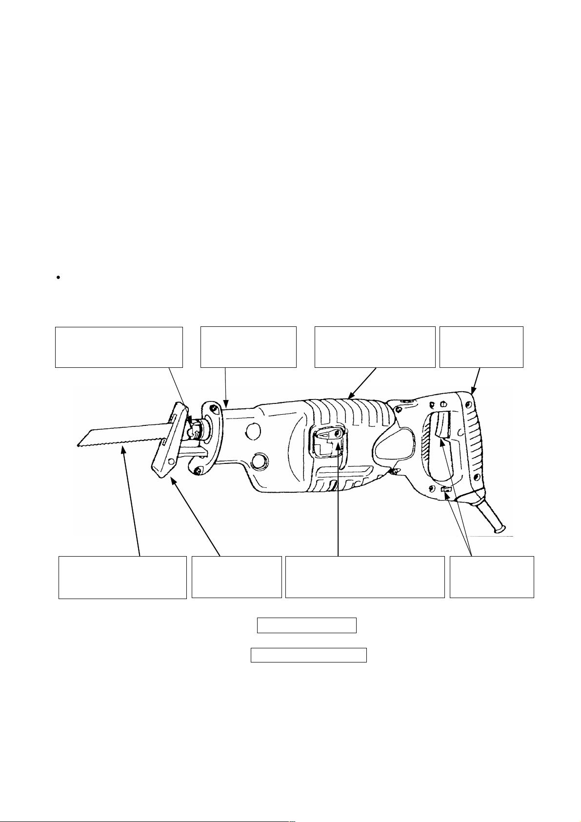
4. SELLING POINTS
Saw blade can be mounted
and removed without the
use of tools
Saw blade can be mounted
in either direction, upward
or downward
Dust- and waterresistant triplesealing construction
Base position is
adjustable without
the use of tools
Sturdy and heat-resistant
thanks to the doublemolded front cover
Top-of-class cutting speed thanks
to the high-power 1000 W motor
and the swing cutting action
+
Soft-touch rubber
grip handle
Convenient
switch trigger and
dial speed scale
Powerful new design
Seven patents pending
--- 1 ---
Page 4
4-1. Selling Point Descriptions
(1) Fast cutting speed
The Model CR 13VA can cut various construction materials fast and efficiently thanks to the high-power motor
whose maximum output is over 1000 W (Model CR 10V: 680 V).
(2) Saw blade can be mounted and removed without the use of tools (patent pending)
Generally, conventional saber saws required a blade holder and a bolt to secure the saw blade.
Such inconvenience was a cause of inefficient operation because the operator kept using a dull blade without
replacing it with a new one, even though a saber saw blade is apt to wear out due to its applications.
The Model CR 13VA eliminates such inconvenience by adopting the Hitachi-original detachable mechanism
that enables one-hand mounting and removal of saw blades without the use of a wrench or other tools.
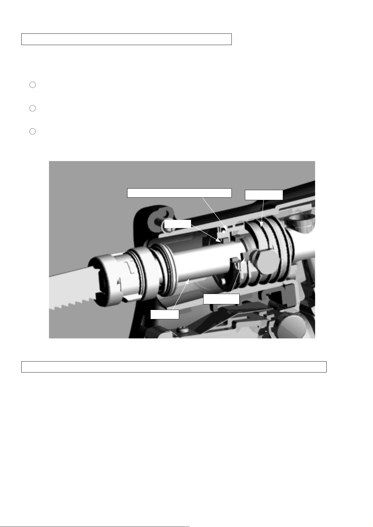
< Features of the Hitachi-original detachable mechanism >
The saw blade can be mounted and removed just by turning the holder sleeve.
1
The sleeve holder can be automatically secured in a released state by turning it all the way. In the
2
released state, the built-in spring force pulls the holder pin back to the correct position automatically. Thus,
saw blades can be smoothly replaced with one hand.
Competitors' products require two-hand operation.
Refer to the Handling Instructions and the leaflets for detailed information
about saw blade replacement.
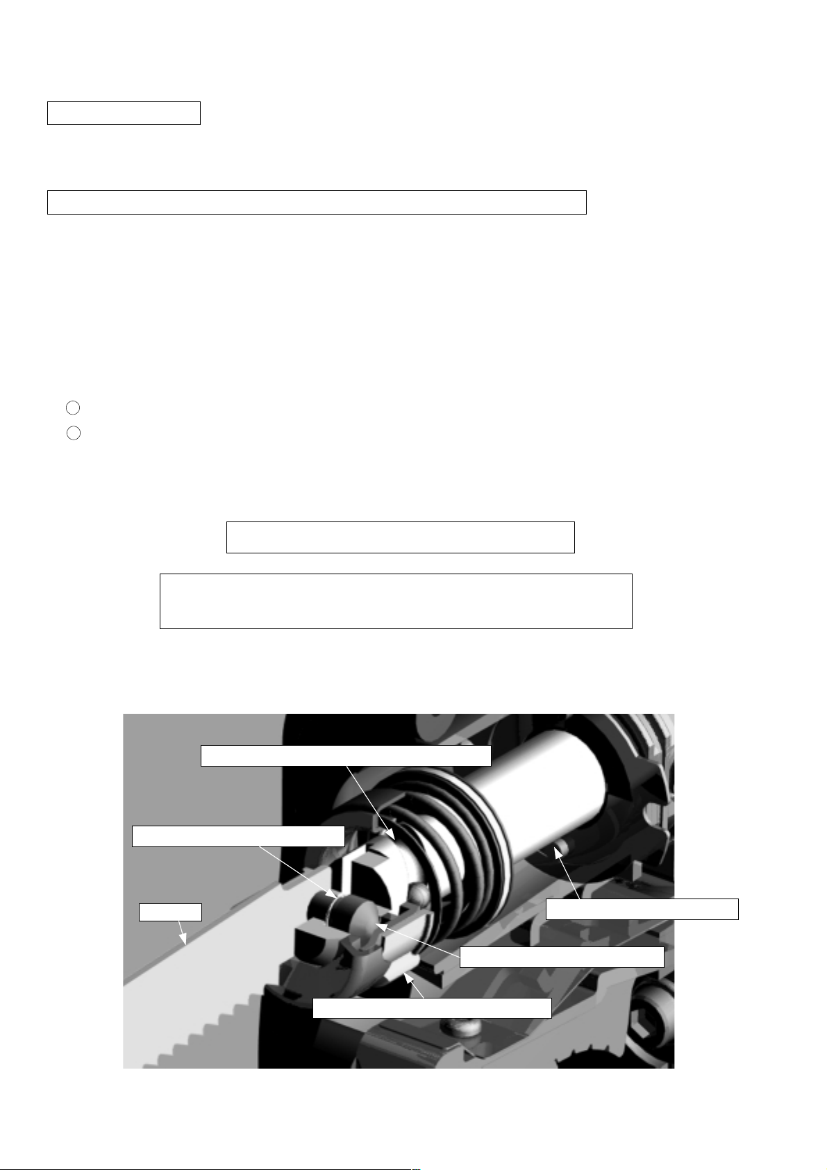
< Construction of detachable mechanism >
Helical groove to pull back the holder sleeve
Spring to pull back the holder pin
Blade
Plunger (reciprocating shaft)
Holder pin to secure the blade
Holder sleeve for blade replacement
--- 2 ---
Page 5
(3) Saw blade can be mounted in either direction, upward or downward
The Model CR 13VA is convenient for cutting materials on the floor or near window frames, and also for
plunge cutting on plywood panels because the saw blade can be installed upside down.
< Cutting on the floor in two-by-four construction >
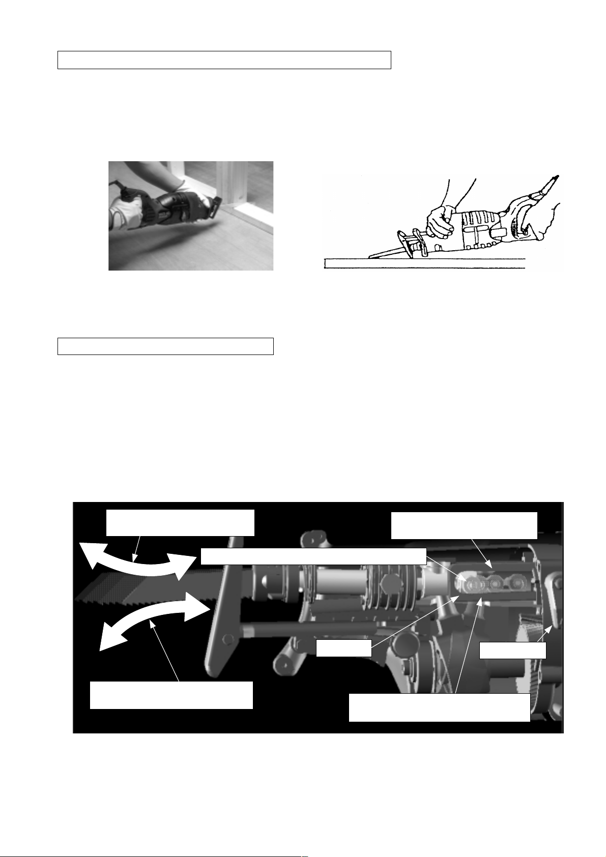
(4) New swing cutting action (patent pending)
Two cutting systems, smooth "straight cutting" and efficient "swing cutting", can be selected with the change
lever. The saw blade is made to forcibly bite into the material when the swing roller at the rear of the plunger
(reciprocating shaft) moves up and down along the slanted surface of the swing rail in the gear cover. Soft
materials such as wood, etc. can be efficiently cut because the reaction during swing cutting is lower than that of
< Plunge cutting on plywood panels >
orbital cutting. The saw blade can be mounted in either facing upward or downward.
< New swing cutting mechanism >
Movement when the saw blade
is mounted normally
Swing roller mounted at the rear of the plunger
Movement when the saw blade is
mounted upside down
Swing rail
Slanted surface when the saw blade is
mounted normally
Slanted surface when the saw
blade is mounted upside down
Change lever
--- 3 ---
Page 6
(5) Dust- and water-resistant triple-sealing construction <patent pending>
The Model CR 13VA has a triple-sealing construction to protect from the large amount of dust generated when
cutting construction materials, autoclaved lightweight concrete, etc. and also from waste water when cutting
pipes.
Dust-resistant felt ring (with backup ring)
1
It prevents dust from entering by way of the plunger (reciprocating shaft).
Dust- and water-resistant seal ring (made of heat-resistant rubber)
2
It prevents dust and waste water from entering by way of the plunger (reciprocating shaft).
Dust- and water-resistant seal sleeve (made of heat-resistant rubber)
3
It prevents dust and waste water from entering through the clearance of the gear case.
< Triple-sealing construction >
Backup ring contacted with the felt ring
Felt ring
Seal ring
Plunger
Seal sleeve
(6) Sturdy and heat-resistant thanks to the double-molded front cover (rubber and plastic) <patent pending>
Front covers made of rubber have been generally used for saber saws. However, such front covers are not so
durable and there is increasing demand for a sturdier saber saw. To cope with this demand, the Model
CR 13VA is equipped with a durable double-molded front cover that is composed of a glass-fiber reinforced
polycarbonate body and a nonskid rubber grip. In addition, heat resistance is improved by making a clearance
between the front cover and the gear case to flow cooling air for the motor.
--- 4 ---
Page 7
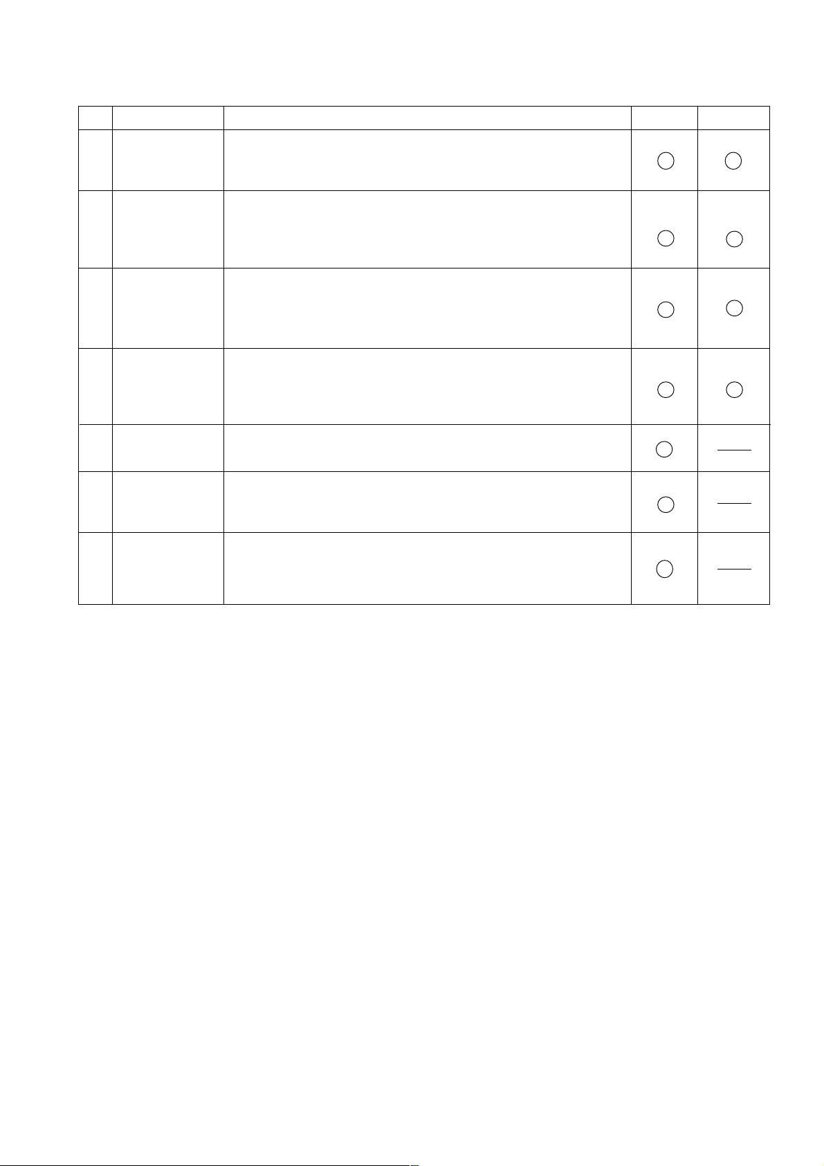
4-2. Descriptions of patent pending
No. OverseasJapan
1
2
3
4
5
6
Patent
Blade holder of
saber saw
Cutting
mechanism of
saber saw
Front cover of
saber saw
Plunger holder
of saber saw
Base of saber
saw
Portable electric
saw
A detachable mechanism that enables one-hand mounting and
removal of saw blades without the use of a wrench or other tools
(competitors' products require two-hand operation)
A swing cutting mechanism in which the saw blade can be
mounted in whichever direction, upward or downward
(In competitors' products and our current products, orbital cutting
is not available when the saw blade is mounted in reverse.)
A durable and heat-resistant front cover of double-molded
construction (rubber and plastic)
(In competitors' products and our current products, a front cover
made of rubber is used and is not as durable.)
A dust- and water-resistant triple-sealing construction.
Sealing quality is not reduced even if the plunger swings.
(In competitors' products and our current products, a doublesealing construction is generally used.)
A base with an added shock-absorbing spring
The entire design of the Model CR 13VA (design right)
(The design is the first of its type including the new front cover
design.)
Descriptions
7
Saw blade for
electric saw
A curved saber saw blade that can cut stainless materials
It is under development with a saw blade manufacturer in Japan.
--- 5 ---
Page 8

5. SPECIFICATIONS
5-1. Specifications
Capacities
Max. cutting size Steel pipe outer diameter 130 mm (5")
Wood thickness (for Europe) 300 mm
Mild steel plate 19 mm (3/4")
Power source AC single phase 50 or 60 Hz
Type of motor
Enclosure
AC single phase series commutator motor
Housing and handle
•••••••••••••••
Grip handle and front cover
Gear cover and inner cover
Type of switch
Full load current
Power input
Variable trigger switch
110 V
120 V
127 V
230 V
•••••••••••••••••••••••••
•••••••••••••••••••••••••
•••••••••••••••••••••••••
•••••••••••••••••••••••••
1,050 W
10 A
9.2 A
8.7 A
4.8 A
1,250 W (for USA)
Max. output (reference)
1,180 W
1,070 W (for USA)
Number of strokes
No load
Full load
•••••••••••••••••••
••••••••••••••••••
0 to 2,800/min.
2,050/min. [dial setting 5]
1,750/min. (for USA) [dial setting 5]
(for USA) 5"
Glassfiber reinforced polyamide resin
••••
Glassfiber reinforced polycarbonate
resin + Leostmer
••••
Aluminum alloy die casting
Stroke
Weight
Packaging
Cord length
Standard accessories
32 mm (1-1/4")
•••••••••••••••••••
Net
Gross
•••••••••••••••
4.0 kg (8.8 lbs.) [without cord]
7.0 kg (15.43 lbs.)
Plastic case (in corrugated cardboard sleeve)
2.5 m (8.2 ft)
Blade No. 103 *
Plastic case
•••••••••••••••
••••••••••••••••••••
1
1
*: This blade is sold separately as an optional accessory in some areas.
--- 6 ---
Page 9

5-2. Optional Accessories
The cutting speed of the Model CR 13VA is substantially higher than that of the current model, however, the
conventional HCS blades may be broken in heavy applications such as house demolition, etc. To cope with this
problem, the BI-METAL blades shown in Table 2 are provided. The BI-METAL blades are tough and rarely break
since they are made by electron-beam welding together of two different types of steels. A very hard steel called
"DM05" (JIS: SKH51 or equivalent molybdenum containing high speed tool steel) or "Matrix II" (JIS: SKH59 or
equivalent cobalt containing high speed tool steel) is used at the cutting edges, and a flexible steel for spring
material is used for the blade main body . So these BI-METAL blades are remarkably stronger than the HCS
blades.
(1) HCS blades
The blade numbers of HCS blades in Table 1 are engraved in the vicinity of the mounting position of each blade.
Select appropriate blades by referring to Tables 1 and 3 below.
Table 1: HCS blades
Blade No. Uses Thickness (mm)
No. 1
No. 2
No. 3
No. 4
No. 5
No. 8
No. 9
No. 95
No. 96
For cutting steel pipes less than 105 mm in outer diameter 2.5 --- 6
For cutting steel pipes less than 30 mm in outer diameter
For cutting steel pipes less than 30 mm in outer diameter
For cutting and roughing lumber
For cutting and roughing lumber
For cutting vinyl chloride pipes less than 105 mm in outer
diameter
For cutting and roughing lumber
For cutting steel pipes less than 130 mm in outer diameter
For cutting steel and stainless pipes less than 105 mm in
outer diameter
For cutting steel and stainless pipes less than 30 mm in
outer diameter
2.5 --- 6
Below 3.5
50 --- 70
Below 30
2.5 --- 15
Below 105
2.5 --- 6
Below 2.5
Below 2.5
--- 7 ---
Page 10

(2) BI-METAL blades
The blade numbers of BI-METAL blades in Table 2 are engraved in the vicinity of the mounting position of each
blade. Select appropriate blades by referring to Table 2 and 3 below.
Table 2: BI-METAL blades
Blade No. Uses
No. 101
No. 102
No. 103
No. 104
No. 105
No. 106
No. 107
No. 108
No. 121
No. 131
No. 132
For cutting steel and stainless pipes less than 60 mm in outer diameter
For cutting steel and stainless pipes less than 130 mm in outer diameter
For cutting steel and stainless pipes less than 60 mm in outer diameter
For cutting steel and stainless pipes less than 130 mm in outer diameter
For cutting steel and stainless pipes less than 60 mm in outer diameter
For cutting steel and stainless pipes less than 130 mm in outer diameter
For cutting steel and stainless pipes less than 60 mm in outer diameter
For cutting steel and stainless pipes less than 130 mm in outer diameter
For cutting and roughing lumber
All purpose
All purpose
Thickness (mm)
2.5 --- 6
2.5 --- 6
2.5 --- 6
2.5 --- 6
2.5 --- 6
2.5 --- 6
Below 3.5
Below 3.5
300
(3) Selection of blades for other materials
Table 3
Material to be cut
Iron plate
Nonferrous metal
Synthetic resin
Material quality
Mild steel plate
Aluminum
Copper
Brass
Phenol resin
Melamine resin etc.
Vinyl chloride
Acrylic resin etc.
Thickness (mm)
2.5 --- 19
Below 3.5
5 --- 20
Below 5
10 --- 50
5 --- 30
10 --- 60
5 -- - 30
Blade No.
No. 1, 2, 101, 102, 103, 104,
105, 106, 131, 132
No. 3, 6, 107, 108
No. 1, 2, 101, 102, 103, 104,
105, 106, 131, 132
No. 3, 6, 107, 108
No. 1, 2, 4, 101, 102, 103, 104,
131, 132
No. 3, 5, 8, 105, 106, 107, 108
No. 1, 2, 4, 101, 102, 103, 104,
131, 132
No. 3, 5, 8, 105, 106, 107, 108
--- 8 ---
Page 11
6. COMPARISONS WITH SIMILAR PRODUCTS
6-1. For USA Market
Maker HITACHI
Model CR 13VA
1. Voltage V
2. Rated current
3. Stroke
4. No-load speed
5. Max. output
6. Dimensions
7. Net weight
8. Vibr ation
9. No-load noise
10. Features
Variable speed
Blade tool-less
Base tool-less
Front cover
Cutting action
Counter balance
L
H
W
A
inch
/min.
W
inch
lbs.
dB
dB
120
11.0
1-1/4
0 -- 2,800
1,070
18.1
6.5
4.1
8.8
126.0
91.0
*T&D
Plastic
& Rubber
(Swing)
CR 10V
115
6.5
1
700 -- 2,200
680
16.4
5.5
3.7
7.9
118.3
81.5
Rubber
(Orbital)
D
P E S
120
10.0 10.0 10.0
1-1/8
0 -- 2,600
920
18.0
7.3
4.2
9.0
126.0
90.8
T
Rubber
(Orbital)
1-1/4
0 -- 3,200
(900)
17.6
6.9
3.6
8.8
115.5
89.3
T&D
Rubber
1-1/4
0 -- 2,900
--- --- ---
17.5
6.7
3.7
8.4
121.5
87.2
T&D
Rubber
6-2. For European Market
Maker HITACHI
Model CR 13VA
1. Voltage V
2. Power input
3. Stroke
4. No-load speed
5. Max. output
6. Dimensions
7. Net weight
8. Vibr ation
9. No-load noise
10. Features
Variable speed
Blade tool-less
Base tool-less
Front cover
Cutting action
Counter balance
L
H
W
W
mm
/min.
W
mm
kg
dB
dB
230
1,050
32
0 -- 2,800
1,180
462
165
106
4.0
126.0
91.0
*T&D
Plastic
& Rubber
(Swing)
CR 10V
720
26
700 -- 2,200
680
417
140
94
3.6
118.3
81.5
D
Rubber
(Orbital)
R Y B
230
1,050 1,000 1,100
28
0 -- 2,600
920
458
185
107
4.0
126.0
90.8
T
Rubber
(Orbital) (Orbital)
32
0 -- 2,800
------ 446
175
92
3.9
115.5
89.3
T&D
Rubber
32
0 -- 2,700
------ 499
175
98
4.4
124.0
93.5
T&D
Rubber
*T: Variable speed control with trigger D: Variable speed control with dial
--- 9 ---
Page 12
7. COMPARISONS IN CUTTING TIME
The following test data should be used for reference purposes only since the cutting time may vary depending on
the operating conditions such as the cutting function, pressing force, type of blade, etc. The graph shows the time
(in sec.) required to cut a piece of each material.
7-1. Cutting Steel Pipes
A steel pipe less than 42 mm (1.65") in inner diameter and
3.2 mm (0.13") in thickness
HITACHI genuine blade No. 103
for cutting steel pipes
Pressing force about 4 kgf (8.8 lbs.)
CR 13VA
CR 10V
A
B
C
D
E
F
Straight cutting
Swing or orbital cutting
Swing cutting
Orbital cutting
Orbital cutting
Orbital cutting function is not provided.
Orbital cutting function is not provided.
Orbital cutting
Orbital cutting function is not provided.
Orbital cutting
0
10
20 30 40 50
Cutting time (sec./cut)
--- 10 ---
Page 13

7-2. Cutting Wood
A piece of lauan 130 mm (5") in width and 43 mm (1.69")
in thickness
HITACHI genuine blade No. 121
for cutting wood
Straight cutting
CR 13VA
A
B
C
Pressing force about 4 kgf (8.8 lbs.)
Swing or orbital cutting
Swing cutting
Orbital cutting
Orbital cutting function is not provided.
Orbital cutting function is not provided.
D
E
F
Orbital cutting
Orbital cutting function is not provided.
Orbital cutting
0
10
20 30 40 50
Cutting time (sec./cut)
--- 11 ---
Page 14

7-3. Cutting Wood with Saw Blade Installed Upside Down
A piece of lauan lumber 130 mm (5") in width and 43 mm
(1.69") in thickness
HITACHI genuine blade No. 121
for cutting wood
CR 13VA
A
B
C
D
Pressing force about 4 kgf (8.8 lbs.)
Straight cutting
Swing or orbital cutting
Swing cutting
Orbital cutting function cannot be used.
Orbital cutting function is not provided.
Orbital cutting function is not provided.
Orbital cutting function cannot be used.
E
F
Orbital cutting function is not provided.
Orbital cutting function cannot be used.
0
10
20 30 40 50
Cutting time (sec./cut)
--- 12 ---
Page 15

7-4. Cutting Operation for Long Blade Life
The service life of a saw blade may vary depending on the operating conditions such as the type of cutting action,
pressing force, etc. Observing the following instructions can lengthen the service life of a saw blade, for reference.
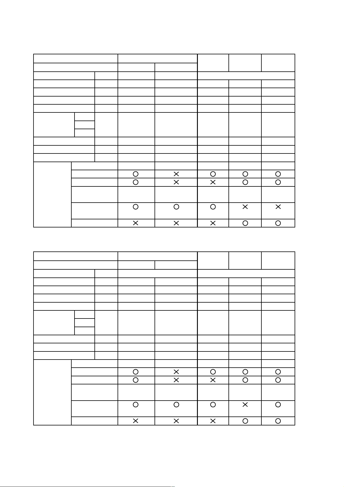
1 Move the saber saw handle up and down repeatedly during the cutting operation
The service life of a saw blade can be lenghtened by moving the saber saw handle up and down repeatedly
once or twice per second during the cutting operation as shown below.
Do not apply undue force to the
workpiece. Appropriate pressing force is
about 4 kgf (8.8 lbs.).
The cutting edge contacts the pipe
in a seesaw motion.
< Explanation >
Heat generated in the cutting operation can significantly affect the service life of the saw blade. Continued cutting
Move the saber saw handle up
and down repeatedly once or
twice per second
operation with the saw blade heated to red hot can decrease the hardness of the saw blade because the cutting
edge is annealed. The saw blade is then worn out in a short time and nothing can be cut. The merits of moving
the saber saw up and down are described below.
The seesaw motion of the saw blade can minimize heating.
1
The effective cutting length of the blade is longer than that of an ordinary cutting operation. Thus, the service
2
life of the saw blade can be lengthened and the cutting speed becomes faster. Cutting wood in the same
manner can also make the cutting speed faster.
Do not apply undue force to the workpiece2
Application of undue force to the workpiece during the cutting operatation can heat up the saw blade and the
number of strokes can decrease, causing reduction of speed. Appropriate pressing force is about 4 kgf (8.8 lbs.).
--- 13 ---
Page 16

8. PRECAUTIONS IN SALES PROMOTION
In the interest of promoting the safest and most efficient use of the Model CR 13VA Reciprocating Saw by all of
our customers, it is very important that at the time of sale, the salesperson carefully ensures that the buyer
seriously recognizes the importance of the contents of the Handling Instructions, and fully understands the
meaning of the precautions listed on the Name Plate attached to each tool.
8-1. Handling Instructions
Although every effort is made in each step of design, manufacture and inspection to provide protection against
safety hazards, the dangers inherent in the use of any electric power tool cannot be completely eliminated.
Accordingly, general precautions and suggestions for the use of electric power tools, and specific precautions and
suggestions for the use of the Reciprocating Saw is listed in the Handling Instructions to enhance the safe and
efficient use of the tool by the customer. Salespersons must be thoroughly familiar with the contents of the
Handling Instructions to be able to offer appropriate guidance to the customers during sales promotion.
8-2. Caution on Name Plate
Each tool is provided with a Name Plate which contains the following basic safety precautions in the use of the
tool.
(1) For Australia, New Zealand and China
CAUTION
Read thoroughly HANDLING INSTRUCTIONS before use.
(2) For U.S.A. and Canada
-- WARNING --
To reduce the risk of injury, user must read and
understand instruction manual.
--- 14 ---
Page 17

9. REPAIR GUIDE
9-1. PRECAUTIONS IN DISASSEMBLY AND REASSEMBLY
Please follow the precautions below for disassembly and reassembly procedures. The circled numbers in the
following figures and the [Bold] numbers in the descriptions below correspond to the item numbers in the Parts
List. Prior to attempting disassembly or replacement of the saw blade, ensure that the power cord plug is
disconnected from the power source.
1. Disassembly
(1) Disassembly of Front Covers (A) and (B) [46] [26] section (Fig. 1)
Remove the Base [22], then the five Tapping Screws (W/Flange) D4 x 25 [43] and the Seal Lock Screw
(W/Washers) M4 x 10 [44]. Remove the Change Knob [45] and Front Cover (A) [46] from the main body.
Remove the Pushing Button [27], Base Lever [25] and Spring (C) [28]. Remove Front Cover (B) [26] and the
Base Adapter [50] from the main body.
Fig. 1
(2) Disassembly of the Gear Cover [31] (Figs. 2 to 4)
Pull out the Change Shaft [34] from the Inner Cover (A) [33]. At this time, be careful not to lose the O-Rings
[35] on both ends of the change shaft.
Fig. 2
--- 15 ---
Page 18

Loosen the Nylock Bolt (W/Flange) M6 x 35 [47] which secures the fan of the armature ass'y (approximately
two turns). Remove the four Machine Screws (W/Washers) M5 x 60 [42] and then pull out the Gear Cover
[31] from the main body. Remove the Nylock Bolt (W/Flange) M6 x 35 [47], then Second Shaft (A) [64]
section and the Sub Shaft [57] can be removed from the Gear Cover [31]. At this time, Second Shaft (A) [64]
section can be easily removed after first pulling out the tip of the Plunger (A) Set [32] approximately 20 mm
from the Gear Cover [31].
20
Fig. 3
Remove the two FT-Machine Screws M4 x 6 [29] and remove the Felt Cover [30]. Secure the Gear Cover
[31] and remove the two Bolts M10 [49] to remove the two Swing Rails [52] from the inside of the Gear Cover
[31]. Pull out the Guide Sleeve Ass'y [9] from the gear cover, then Plunger (A) Set [32] and the Guide Sleeve
Ass'y [9] can be removed in an assembled state. At this time, remove the Swing Roller [53] with the Pin D6
[54] mounted. Remove the two Machine Screws M4 x 10 [59] from the inside of the gear cover and then
remove Bearing Cover (B) [58] and the Ball Bearing 6003DDCMPS2S [56].
Fig. 4
--- 16 ---
Page 19

(3) Disassembly of the blade mounting section (Fig. 5)
Remove the Retaining Ring (E-Type) for D14 Shaft [2] from Plunger (A) Set [32] with a flatblade screwdriver.
At this time, be careful that Spring (A) [19] is pushing against the retaining ring. Next, slide the Guide Washer
[17] backward and remove the two Steel Balls D4.76 [15]. Move Holder Sleeve (B) [14] backward and adjust
the position of the notch on Holder Sleeve (B) [14] (see Fig. 16) then remove the Holder Pin [11] and Spring
(B) [12] with a magnet. At this time, be careful not to damage Spring (B) [12] by applying undue force or
forgetting to remove it. Remove Holder Sleeve (A) [13], Holder Sleeve (B) [14], Holder Sleeve (C) [16], Guide
Washer [17], Dust Washer [18], Spring (A) [19], Washer (D) [20], Thrust Bearing [21], Washer (E) [1] and
Washer (F) [3] from Plunger (A) Set [32].
Fig. 5
(4) Disassembly of the Guide Sleeve Ass'y [9] section (Fig. 6)
Remove the O-Ring [4] from the rim of the Seal Sleeve [6] and pull out the Felt Washer [5], Seal Sleeve [6]
and V-Ring [7] from the Guide Sleeve Ass'y [9]. Next, remove the Plunger Sleeve [10] by pressing it from
underneath Plunger (A) Set [32] with a hand press (see Fig. 19). Remove the Pin D6 [54] and then Plunger
(A) Set [32] from the rear of the Guide Sleeve Ass'y [9].
Fig. 6
--- 17 ---
Page 20

(5) Disassembly of the Second Shaft (A) [64] section (Fig. 7)
Remove the Retaining Ring for D17 Shaft [60] from Second Shaft (A) [64]. While holding the side surface of
the Recipro Plate [61], push the end surface of Second Shaft (A) [64] (parallel with the side surface of the
Recipro Plate [61]) with a hand press and remove the Recipro Plate [61] in an assembled state. Next, while
holding the side surface of the Gear [65], push the end surface of Second Shaft (A) [64] with a hand press
and remove the Gear [65] and the Ball Bearing 608VVC2PS2L [66]. Remove the Retaining Ring for D35 Hole
[63] from the Recipro Plate [61], then remove the two Ball Bearings 6003VVCMPS2L [62] from the Recipro
Plate [61].
Fig. 7
(6) Disassembly of Inner Cover (A) [33] and the Housing [40] section (Fig. 8)
Remove the two Brush Caps [37] and the two Carbon Brushes [38]. Tap the air vents of the Housing [40]
slightly with a plastic hammer, then Inner Cover (A) [33] can be removed from the housing together with the
Armature Ass'y [70]. At this time, be careful not to tap the fan with the plastic hammer. Remove the Fan
Guide [71] from the inside of the housing.
Fig. 8
(7) Disassembly of Inner Cover (A) [33] and the Armature Ass'y [70] section (Fig. 9)
While holding the side surface of Inner Cover (A) [33] where the Armature Ass'y [70] is assembled, push the
end surface of the armature pinion with a hand press and remove it. Remove the two Flat Hd. Screws M4 x 8
[69] to remove the Bearing Cover [68] and the Ball Bearing 6001VVCMPS2L [67].
Fig. 9
--- 18 ---
Page 21

(8) Disassembly of Handles (A) [74] and (B) [80] section (Fig. 10)
Remove the six Tapping Screws (W/Flange) D4 x 25 [43]. Remove the Grip Cover [81] by pulling it backward
and remove Handle (A) [74]. Then, the Switch Trigger [76] can be removed.
80
81
Fig. 10
(9) Disassembly of Handle (B) [80] and the Switch [75] section (Fig. 11)
Disconnect the two internal wires coming from the Stator [73] and the two internal wires coming from the Cord
[85] by loosening the small screw on the switch. Then, the Switch [75] can be removed. If the Noise
Suppressor [83] is connected to the switch, cut the internal wires and then remove the switch because the
internal wires coming from the stator and the triac are crimped to the noise suppressor through Tube (D) [79].
Fig. 11
(10) Disassembly of the Housing [40] and the Brush Holder [39] section (Fig. 12)
Remove the CB terminal coming from the Stator [73] from the Brush Holder [39] and remove the Brush
Holder [39] from the inside of the Housing [40] with a flatblade screwdriver. (No screw or adhesive was used
for mounting.)
Fig. 12
--- 19 ---
Page 22

2. Reassembly
Reassembly can be accomplished by following the disassembly procedures in reverse. However, special
attention should be given to following items.
(1) Press-fitting the Recipro Plate [61] ass'y into Second Shaft (A) [64] (Fig.13)
Tool required: Special repair tool J-315
Mount the two Ball Bearings 6003VVCMPS2L [62] and the Retaining Ring for D35 Hole [63] to the Recipro
Plate [61] to complete the assembly (recipro plate ass'y).
(a) If the Gear [65] and the Ball Bearing 608VVC2PS2L [66] are not mounted to Second Shaft (A) [64],
mount Second Shaft (A) [64] and the recipro plate ass'y to the special repair tool J-315 and press-fit it in
the direction of the arrow with a hand press as shown in Fig. 13-a.
(b) When the Gear [65] and the Ball Bearing 608VVC2PS2L [66] are mounted to Second Shaft (A) [64],
mount Second Shaft (A) [64] and the recipro plate ass'y to the special repair tool J-315 and press-fit it in
the direction of the arrow with a hand press as shown in Fig. 13-b.
Be careful of the direction when press-fitting the recipro plate ass'y.
J-315
J-315
J-315
Fig. 13-a
(2) Press-fitting Metal (A) [8] into the guide sleeve (Fig. 14)
(Metal (A) [8] and the guide sleeve are supplied together as
the Guide Sleeve Ass'y [9].)
Tool required: Special repair tool J-316 (adjusted to the
proper dimensions)
J-315
Fig. 13-b
Guide sleeve
Insert Metal (A) [8] into the press-fitting portion of the guide
sleeve so that the outer flat section of the metal can be seen
from the 8 mm dia. hole of the guide sleeve. (An inspection
hole is provided on one side of the metal.) Mount the two
special repair tools J-316 in the 8 mm dia. hole as shown in
Fig. 14. Push the guide sleeve in the direction shown by the
arrow as far as it will go with a hand press.
--- 20 ---
8 mm dia. hole
J-316
8 mm dia. hole
J-316
J-316
Fig. 14
Page 23

(3) Reassembly of the blade mounting section (Figs. 15, 16 and 17)
Apply Doubrex 251 grease to the inner circumference of Holder Sleeve (B) [14] and the cam groove of
Plunger (A) Set [32]. Mount Washer (E) [1], Thrust Bearing [21], Washer (D) [20], Spring (A) [19], Dust
Washer [18], Guide Washer [17], Holder Sleeve (C) [16], Holder Sleeve (B) [14] and Holder Sleeve (A) [13] in
the Plunger (A) Set [32] through the tip in order (Fig. 15).
Next, align the hole of the Plunger (A) Set [32] with the notches of Holder Sleeve (A) [13] and Holder Sleeve
(B) [14] and then insert Spring (B) [12] and the Holder Pin [11] into the hole. Push in the Holder Pin [11] to
eject Holder Sleeves (B) [14] and (C) [16] forward (as shown in Fig. 16). Turn them about 90˚
counterclockwise viewing from the tip (as shown in Fig. 16), then insert the two Steel Balls D4.76 [15] (in
the direction of the arrow marks shown in Figs. 16 and 17). Slide all the parts up to Washer (E) [1] forward (as
shown in Fig. 17) and mount the Retaining Ring (E-type) for D14 Shaft [2] securely by adjusting Spring (A)
[19]. Be careful of the projections and depressions on Holder Sleeve (B) [14] and Holder Sleeve (C) [16]
when mounting. After reassembly, test mount and remove a saw blade to check for proper operation.
C
B
Fig. 15
A
Notch
Notch
Hole
Fig. 16
Arrow mark
Arrow mark
Fig. 17
--- 21 ---
Page 24

(4) Press-fitting plunger (A) into the plunger sleeve (Figs. 18 and 19)
Tool required: Special repair tool J-317
Apply Nippeco SEP-3A grease to the sliding portion of plunger (A) and insert it into the Guide Sleeve Ass'y [9].
Insert the Pin D6 [54] into plunger (A). Mount it to the special repair tool J-317 and press-fit it in the direction
of the arrow as shown in Fig. 18. At this time, be careful not to gall the plunger sleeve. After reassembly,
check that plunger (A) slides smoothly. For reference, the special repair tool J-317 can also be used for
pulling out the plunger sleeve as shown in Fig. 19.
Plunger (A)
Fig. 18
J-317
Fig. 19
Plunger sleeve
J-317
J-317
Plunger sleeve
J-317
Plunger (A)
(5) Others
* Be careful not to dislodge the Felt Washer [5]. (Fig. 20)
The Felt Washer [5] is inserted in the Seal Sleeve [6]. The O-Ring [4] is provided around the seal sleeve to
make closer contact between the felt washer and plunger (A) and also to increase the dust-resistance.
Moving plunger (A) after mounting the felt washer can dislodge the felt washer. Hold Washer (F) [3] with
your hand to prevent the felt washer from becoming dislodged when moving plunger (A).
Fig. 20
--- 22 ---
Page 25

* Be careful not to damage Washer (F) [3]. (Fig. 21)
Washer (F) has an oval shape to fit the inside of the Gear Cover [31]. Therefore, perform disassembly and
reassembly so that washer (F) is properly aligned with the shape of the gear cover.
Fig. 21
*Be careful of the direction of the Cord Clip [78]. (Fig. 22)
Cord dia.: More than 6.4 mm,
8.5 mm or less
Fig. 22
*Precaution when mounting the Armature Ass'y [70] in the Housing [40]
Prior to mounting the Armature Ass'y [70] in the Housing [40], press-fit the Ball Bearing 6001VVCMPS2L [67]
to prevent the Armature Ass'y [70] from becoming dislodged from the ball bearing portion at the fan side
when removing the Armature Ass'y [70] from the Housing [40]. (Fig. 9)
Cord dia.: More than 8.5 mm,
10.8 mm or less
--- 23 ---
Page 26

9-2. Lubrication
(1) Nippeco SEP-3A grease
Lip portion of the V-Ring [7] Inner circumference of the Swing Roller [53]
Sphere portion of the Recipro Plate [61] Both sides of the Thrust Bearing [21]
Inner circumferene of the Guide Sleeve Ass'y [9] and Metal (A) [8]
Apply 45 g of Nippeco SEP-3A to the Gear Cover [31].
(2) Doubrex 251 grease
Steel Ball D4.76 [15] Inner circumference of Holder Sleeve (B) [14]
Cam groove portion of Plunger (A) Set [32]
9-3. Tightening Torques
FT-Machine Screw M4 x 6 [29]
Seal Lock Screw (W/Washers) M4 x 10 [44]
Machine Screw M4 x 10 [59]
Flat Hd. Screw M4 x 8 [69]
Tapping Screw D4 x 8 [23]
Tapping Screw (W/Flange) D4 x 25 [43]
Tapping Screw (W/Flange) D4 x 16 [77]
Machine Screw (W/Washers) D5 x 60 [42]
Hex. Hd. Tapping Screw D 5 x 55 [72]
Nylock Bolt (W/Flange) M6 x 35 [47]
Bolt M10 [49]
••••••••••••••••••••••••••••••••••••••••••••••••••••••••••••••
•••••••••••••••••••••••••••••••••••••••••••
••••••••••••••••••••••••
••••••••••••••••••••••••••••••••••••••••••••••
•••••••••••••••••••••••••••••••••••••••••••••••••
•••••••••••••••••••••••••••••••••••••••••••••••••
•••••••••••••••••••••••••••••••
••••••••••••••••••••••••••••••
•••••••••••••••••••••••••••
••••••••••••••••••••••••••••••••
••••••••••••••••••••••••••••
9.8 2.0 N•m (100 20 kgf•cm, 86.8 17.4 in-lbs.)
12.3 2.5 N•m (125 25 kgf•cm, 108.5 21.7 in-lbs.)
1.2 0.3 N•m (12 3 kgf•cm, 10.4 2.6 in-lbs.)
1.8 0.4 N•m (18 4 kgf•cm, 15.6 3.5 in-lbs.)
1.8 0.4 N•m (18 4 kgf•cm, 15.6 3.5 in-lbs.)
1.8 0.4 N•m (18 4 kgf•cm, 15.6 3.5 in-lbs.)
1.8 0.4 N•m (18 4 kgf•cm, 15.6 3.5 in-lbs.)
2.0 0.5 N•m (20 5 kgf•cm, 17.4 4.3 in-lbs.)
2.0 0.5 N•m (20 5 kgf•cm, 17.4 4.3 in-lbs.)
2.5 0.5 N•m (25 5 kgf•cm, 21.7 4.3 in-lbs.)
3.4 0.7 N•m (35 7 kgf•cm, 30.4 6.1 in-lbs.)
9-4. Wiring Diagram
Carefully ensure that wiring is accomplished as illustrated below. As incorrect wiring will result in lack of rotation,
reverse rotation or other malfunctions, close attention is absolutely necessary. Also, be careful of the presence or
absence of Tube (D) [79] for working.
Switch body
Noise suppressor
Noise suppressor earth wire
Triac ass'y
Dial resistor
Fig. 23
--- 24 ---
Page 27

For stator ass'y, or for stator ass'y
and noise suppressor
For cord
For cord
With noise suppressor type
Terminal
For triac ass'y, or for triac ass'y
and noise suppressor
For stator ass'y
Fig. 24
Armature
Dial
resistor
Triac
ass'y
120 V type
Stator
Black
Black
Red
Blue
Tube (D)
ArmatureArmature
Red
Fig. 25
Stator
R1
R2
T2
Switch body
T1
M1 M2
1
Cord
2
Tube (D)
Noise
suppressor
Other type
Armature
Stator
Dial
resistor
Triac
ass'y
Black
Black
Red
Blue T1
Red
Fig. 26
R1
R2
T2
Switch body
Dial
M1 M2
1
Cord Cord
2
--- 25 ---
resistor
Triac
ass'y
Black
Black
Red
Blue
Tube (D)
Red
Fig. 27
R1
R2
T2
Switch body
T1
M1 M2
1
2
Page 28

10. CONFIRMATION AFTER REASSEMBLY
10-1. Lead Wire Precautions
When connecting lead wires, be very careful not to remove the insulation covering of each lead wire more than
needed. Also, ensure that the lead wires are not pinched between the mating surfaces of the handle.
10-2. Insulation T ests
On completion of disassembly and repair, measure the insulation resistatance and conduct dielectric strength test.
Insulation resistance: 7MΩ or more with DC 500 V Megohm Tester
Dielectric strength: AC 4000 V/1 minute, with no abnormalities … 220 V to 240 V
AC 2500 V/1 minute, with no abnormalities … 110 V to 127 V
10-3. No-Load Current Value
After no-load operation for 30 minutes, the no-load current value should be as specified below at a frequency of
50/60 Hz.
110 V … 5.2 A max. 115 V … 5.0 A max. 120 V … 4.7 A max.
127 V … 4.5 A max. 220 V … 2.6 A max. 230 V … 2.5 A max.
240 V … 2.4 A max.
--- 26 ---
Page 29

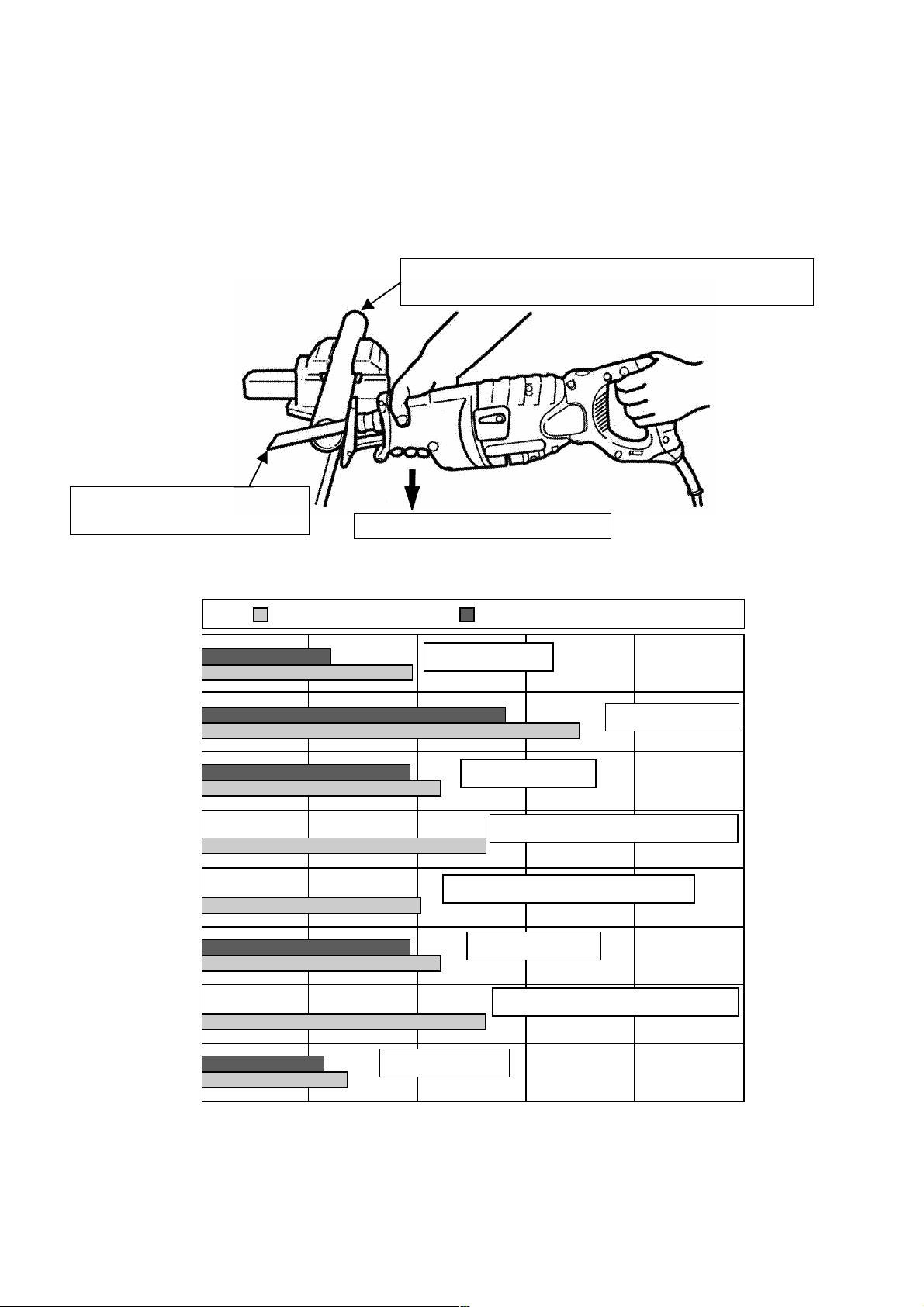
11. STANDARD REPAIR TIME (UNIT) SCHEDULES
MODEL 10 20 30 40
Fixed
Variable
Work Flow
CR 13VA
General Assembly
Handle (A),(B)
Switch
Cord
Cord Armor
Switch Trigger
Front Cover (A)
Front Cover (B)
Inner Cover (A)
Armature Ass'y
Ball Bearing
(6001VV)
Ball Bearing
(608VV)
Change Shaft
O-Ring
Ball Bearing
(6003DD)
Sub Shaft
Recipro Plate
Ball Bearing
(6003VV) x 2
Second Shaft (A)
Gear
Ball Bearing
(608VV)
Housing
Stator
50
60
Plunger (A)
Guide Sleeve
Metal (A)
Seal Sleeve
O-Ring (S-24)
Thrust Bearing
Spring (A)
Gear Cover
Base
Ass'y
--- 27 ---
Page 30

LIST NO. 0786
ELECTRIC TOOL PARTS LIST
SABER SAW
Model CR 13VA
1999•12•20
(E1)
--- 28 ---
Page 31

PARTS
ITEM
CODE NO. DESCRIPTION
NO.
1 318-484 WASHER (E) 1
2 318-453 RETAINING RING (E-TYPE) FOR D14 SHAFT 1
3 318-457 WASHER (F) 1
4 878-609 O-RING (S-24) 1
5 318-458 FELT WASHER 1
6 318-460 SEAL SLEEVE 1
7 318-459 V-RING 1
8 318-463 METAL (A) 1
9 318-462 GUIDE SLEEVE ASS'Y 1 INCLUD.8
10 PLUNGER SLEEVE 1
11 318-481 HOLDER PIN 1
12 318-483 SPRING (B) 1
13 318-478 HOLDER SLEEVE (A) 1
14 318-479 HOLDER SLEEVE (B) 1
15 959-149 STEEL BALL D4.76 (10 PCS.) 2
16 318-480 HOLDER SLEEVE (C) 1
17 318-477 GUIDE WASHER 1
18 318-487 DUST WASHER 1
19 318-482 SPRING (A) 1
20 318-486 WASHER (D) 1
21 318-485 THRUST BEARING 1
22 318-455 BASE 1
23 310-222 TAPPING SCREW D4X8 1
24 318-495 HOLDER SPRING 1
25 318-497 BASE LEVER 1
26 318-471 FRONT COVER (B) 1
27 318-496 PUSHING BUTTON 1
28 318-494 SPRING (C) 1
29 677-495 FT-MACHINE SCREW M4X6 2
30 318-456 FELT COVER 1
31 318-468 GEAR COVER 1
32 318-824 PLUNGER (A) SET 1 INCLUD.10
33 318-469 INNER COVER (A) 1
34 318-489 CHANGE SHAFT 1
35 872-654 O-RING (1AP-10) 2
36 974-577 RETAINING RING (E-TYPE) FOR D7 SHAFT 1
37 945-161 BRUSH CAP 2
38 999-043 CARBON BRUSH (1 PAIR) 2
39 958-900 BRUSH HOLDER 2
40 318-506 HOUSING (GREEN) 1
41 NAME PLATE 1
42 307-224
43 307-028
44 303-851
45 318-490 CHANGE KNOB 1
46 318-470 FRONT COVER (A) 1
47 318-451 NYLOCK BOLT (W/FLANGE) M6X35 1
48 318-452 WASHER (G) 1
49 318-493 BOLT M10 2
50 318-454 BASE ADAPTER 1
51 318-461 CUSHION RUBBER 1
MACHINE SCREW (W/WASHERS) M5X60 (BLACK)
TAPPING SCREW (W/FLANGE) D4X25 (BLACK)
SEAL LOCK SCREW (W/WASHERS) M4X10 (BLACK)
: ALTERNATIVE PARTS
*
NO.
USED
4
11
1
--- 29 ---
CR 13VA
REMARKS
12 --- 99
Page 32

ITEM
* 70 360-514C ARMATURE 110V-115V 1
* 70 360-514U ARMATURE ASS'Y 120V-127V 1 INCLUD.66,67
* 70 360-514E ARMATURE 220V-230V 1
* 70 360-514F ARMATURE 240V 1
* 72 961-501 HEX. HD. TAPPING SCREW D5X60 2
* 72 953-174 HEX. HD. TAPPING SCREW D5X55 2 FOR USA
* 73 340-459H STATOR 110V-115V 1
* 73 340-459G STATOR 120V-127V 1 FOR USA
* 73 340-459J STATOR 220V-230V 1
* 73 340-459E STATOR 220V-230V 1 FOR IND,SYR,HKG
* 73 340-459K STATOR 240V 1
* 75 318-817 SWITCH 1 FOR GBR(110V)
* 75 318-504 SWITCH 1 FOR USA
* 75 318-505 SWITCH 1
* 82 938-108 TERMINAL 1 FOR NOISE SUPPRESSOR
* 83 994-273 NOISE SUPPRESSOR 1 EXCEPT SYR,USA,IND,HKG
* 84 953-327 CORD ARMOR D8.8 1
* 84 938-051 CORD ARMOR D10.1 1
* 85 500-201Z CORD 1 (CORD ARMOR D10.1) FOR TPE
* 85 500-234Z CORD 1 (CORD ARMOR D8.8)
* 85 500-245Z CORD 1 (CORD ARMOR D10.1) FOR SYR
* 85 500-435Z CORD 1 (CORD ARMOR D8.8) FOR HKG,GBR(230V)
* 85 500-439Z CORD 1 (CORD ARMOR D8.8) FOR AUS,NZL
* 85 500-461Z CORD 1 (CORD ARMOR D8.8) FOR GBR(110V)
* 85 500-447Z CORD 1 (CORD ARMOR D8.8) FOR SUI
12 --- 99
CODE NO. DESCRIPTION
NO.
52 318-488 SWING RAIL 2
53 318-492 SWING ROLLER 2
54 318-491 PIN D6 1
55 HITACHI LABEL 1
56 600-3DD BALL BEARING 6003DDCMPS2S 1
57 318-475 SUB SHAFT 1
58 318-476 BEARING COVER (B) 1
59 949-216 MACHINE SCREW M4X10 (10 PCS.) 2
60 967-261 RETAINING RING FOR D17 SHAFT 1
61 318-466 RECIPRO PLATE 1
62 600-3VV BALL BEARING 6003VVCMPS2L 2
63 939-556 RETAINING RING FOR D35 HOLE (10 PCS.) 1
64 318-474 SECOND SHAFT (A) 1
65 318-473 GEAR 1
66 608-VVM BALL BEARING 608VVC2PS2L 2
67 600-1VV BALL BEARING 6001VVCMPS2L 1
68 302-435 BEARING COVER 1
69 949-321 FLAT HD. SCREW M4X8 (10 PCS.) 2
71 318-467 FAN GUIDE 1
74 318-508 HANDLE (A) (GREEN) 1
76 318-499 SWITCH TRIGGER 1
77 984-750 TAPPING SCREW (W/FLANGE) D4X16 2
78 937-631 CORD CLIP 1
79 981-373 TUBE (D) 4
80 318-509 HANDLE (B) (GREEN) 1
81 318-472 GRIP COVER 1
: ALTERNATIVE PARTS
*
NO.
USED
REMARKS
--- 30 ---
CR 13VA
Page 33

PARTS
ITEM
* 85 500-434Z CORD 1 (CORD ARMOR D8.8) FOR USA
* 85 500-455Z CORD 1 (CORD ARMOR D8.8) FOR CHNOR
CODE NO. DESCRIPTION
No.
NO.
USED
REMARKS
STANDARD ACCESSORIES
ITEM
CODE NO. DESCRIPTION
No.
501 318-613
502 312-831 CASE 1
SABER SAW BLADES NO.103 150L P.14 (5 PCS.)
NO.
USED
1
REMARKS
CR 13VA
OPTIONAL ACCESSORIES
ITEM
CODE NO. DESCRIPTION
No.
601 959-610 SABER SAW BLADES NO.1 (5 PCS.) 1
602 958-182 SABER SAW BLADES NO.2 (5 PCS.) 1
603 958-183 SABER SAW BLADES NO.3 (5 PCS.) 1
604 959-611 SABER SAW BLADES NO.4 (5 PCS.) 1
605 958-185 SABER SAW BLADES NO.5 (5 PCS.) 1
606 958-188 SABER SAW BLADES NO.8 (5 PCS.) 1
607 996-427 SABER SAW BLADES NO. 9 (3 PCS.) 1
608 959-799 SABER SAW BLADES NO.95 (3 PCS.) 1
609 959-800 SABER SAW BLADES NO.96 (3 PCS.) 1
610 318-611
611 318-612
612 318-614
613 318-615
614 318-616
615 318-617
616 318-618
617 318-619
618 318-620
619 318-621 SABER SAW BLADES NO.132 203L (5 PCS.) 1
SABER SAW BLADES NO.101 150L P.10 (5 PCS.)
SABER SAW BLADES NO.102 228L P.10 (5 PCS.)
SABER SAW BLADES NO.104 228L P.14 (5 PCS.)
SABER SAW BLADES NO.105 150L P.18 (5 PCS.)
SABER SAW BLADES NO.106 228L P.18 (5 PCS.)
SABER SAW BLADES NO.107 150L P.24 (5 PCS.)
SABER SAW BLADES NO.108 228L P.24 (5 PCS.)
SABER SAW BLADES NO.121 300L P.6 (5 PCS.)
SABER SAW BLADES NO.131 305L P.10/14(5 PCS.)
NO.
USED
1
1
1
1
1
1
1
1
1
REMARKS
: ALTERNATIVE PARTS
*
--- 31 ---
Printed in Japan
(991220 N)
12 --- 99
Page 34

LIST NO. 0786
ELECTRIC TOOL PARTS LIST
SABER SAW
Model CR 13VA
2000•2•15
[For the U.S.A. and Canada only]
(E1)
--- 32 ---
Page 35

PARTS
ITEM
CODE NO. DESCRIPTION
NO.
1 318-484 WASHER (E) 1
2 318-453 RETAINING RING (E-TYPE) FOR D14 SHAFT 1
3 318-457 WASHER (F) 1
4 878-609 O-RING (S-24) 1
5 318-458 FELT WASHER 1
6 318-460 SEAL SLEEVE 1
7 318-459 V-RING 1
8 318-463 METAL (A) 1
9 318-462 GUIDE SLEEVE ASS'Y 1 INCLUD.8
10 PLUNGER SLEEVE 1
11 318-481 HOLDER PIN 1
12 318-483 SPRING (B) 1
13 318-478 HOLDER SLEEVE (A) 1
14 318-479 HOLDER SLEEVE (B) 1
15 959-149 STEEL BALL D4.76 (10 PCS.) 2
16 318-480 HOLDER SLEEVE (C) 1
17 318-477 GUIDE WASHER 1
18 318-487 DUST WASHER 1
19 318-482 SPRING (A) 1
20 318-486 WASHER (D) 1
21 318-485 THRUST BEARING 1
22 318-455 BASE 1
23 310-222 TAPPING SCREW D4X8 1
24 318-495 HOLDER SPRING 1
25 318-497 BASE LEVER 1
26 318-471 FRONT COVER (B) 1
27 318-496 PUSHING BUTTON 1
28 318-494 SPRING (C) 1
29 677-495 FT-MACHINE SCREW M4X6 2
30 318-456 FELT COVER 1
31 318-468 GEAR COVER 1
32 318-824 PLUNGER (A) SET 1 INCLUD.10
33 318-469 INNER COVER (A) 1
34 318-489 CHANGE SHAFT 1
35 872-654 O-RING (1AP-10) 2
36 974-577 RETAINING RING (E-TYPE) FOR D7 SHAFT 1
37 945-161 BRUSH CAP 2
38 999-043 CARBON BRUSH (1 PAIR) 2
39 958-900 BRUSH HOLDER 2
40 318-506 HOUSING (GREEN) 1
41 NAME PLATE 1
42 307-224
43 307-028
44 303-851
45 318-490 CHANGE KNOB 1
46 318-470 FRONT COVER (A) 1
47 318-451 NYLOCK BOLT (W/FLANGE) M6X35 1
48 318-452 WASHER (G) 1
49 318-493 BOLT M10 2
50 318-454 BASE ADAPTER 1
51 318-461 CUSHION RUBBER 1
MACHINE SCREW (W/WASHERS) M5X60 (BLACK)
TAPPING SCREW (W/FLANGE) D4X25 (BLACK)
SEAL LOCK SCREW (W/WASHERS) M4X10 (BLACK)
: ALTERNATIVE PARTS
*
NO.
USED
4
11
1
--- 33 ---
CR 13VA
REMARKS
2 --- 00
Page 36

PARTS
ITEM
* 70 360-514U ARMATURE ASS'Y 120V-127V 1 INCLUD.66,67 FOR USA
* 72 953-174 HEX. HD. TAPPING SCREW D5X55 2 FOR USA
* 73 340-459G STATOR 120V-127V 1 FOR USA
* 75 318-504 SWITCH 1 FOR USA
* 82 938-108 TERMINAL 1 FOR NOISE SUPPRESSOR
* 83 994-273 NOISE SUPPRESSOR 1 EXCEPT SYR,USA,IND,HKG
* 84 953-327 CORD ARMOR D8.8 1
* 85 500-434Z CORD 1 (CORD ARMOR D8.8) FOR USA
CODE NO. DESCRIPTION
NO.
52 318-488 SWING RAIL 2
53 318-492 SWING ROLLER 2
54 318-491 PIN D6 1
55 HITACHI LABEL 1
56 600-3DD BALL BEARING 6003DDCMPS2S 1
57 318-475 SUB SHAFT 1
58 318-476 BEARING COVER (B) 1
59 949-216 MACHINE SCREW M4X10 (10 PCS.) 2
60 967-261 RETAINING RING FOR D17 SHAFT 1
61 318-466 RECIPRO PLATE 1
62 600-3VV BALL BEARING 6003VVCMPS2L 2
63 939-556 RETAINING RING FOR D35 HOLE (10 PCS.) 1
64 318-474 SECOND SHAFT (A) 1
65 318-473 GEAR 1
66 608-VVM BALL BEARING 608VVC2PS2L 2
67 600-1VV BALL BEARING 6001VVCMPS2L 1
68 302-435 BEARING COVER 1
69 949-321 FLAT HD. SCREW M4X8 (10 PCS.) 2
71 318-467 FAN GUIDE 1
74 318-508 HANDLE (A) (GREEN) 1
76 318-499 SWITCH TRIGGER 1
77 984-750 TAPPING SCREW (W/FLANGE) D4X16 2
78 937-631 CORD CLIP 1
79 981-373 TUBE (D) 4
80 318-509 HANDLE (B) (GREEN) 1
81 318-472 GRIP COVER 1
NO.
USED
REMARKS
CR 13VA
2 --- 00
: ALTERNATIVE PARTS
*
--- 34 ---
Page 37

STANDARD ACCESSORIES
ITEM
CODE NO. DESCRIPTION
No.
502 312831 CASE 1
551
8" BI-M ALLPURP Progressive Recip. Blade 1PC
NO.
USED
1 See Item No.677
CR 13VA
REMARKS
OPTIONAL ACCESSORIES [Available for the U.S. and Canadian Market only
ITEM
CODE NO. DESCRIPTION
No.
651 725300 6" HCS WOOD 6TPI Recip. Blade 5PCS 1
652 725301 9" HCS WOOD 5TPI Recip. Blade 5PCS 1
653 725302 12" HCS WOOD 6TPI Recip. Blade 5PCS 1
654 725310 6" BI-M WOODNAIL 6TPI Recip. Blade 5PCS 1 TAPER Blade Back
655 725311 6" BI-M WOODNAIL 6TPI Recip. Blade 5PCS 1 SCROLL Blade Back
656 725312 6" BI-M WOODNAIL 6TPI Recip. Blade 5PCS 1 STRAIGHT Blade Back
657 725313 9" BI-M WOODNAIL 6TPI Recip. Blade 5PCS 1
658 725314
659 725320 6" BI-M METAL 10TPI Recip. Blade 5PCS 1
660 725321 9" BI-M METAL 10TPI Recip. Blade 5PCS 1
661 725322 6" BI-M METAL 14TPI Recip. Blade 5PCS 1
662 725323 9" BI-M METAL 14TPI Recip. Blade 5PCS 1
663 725324 6" BI-M METAL 18TPI Recip. Blade 5PCS 1
664 725325 6" BI-M METAL 24TPI Recip. Blade 5PCS 1
665 725326 9" BI-M METAL 18TPI Recip. Blade 5PCS 1
666 725327 9" BI-M METAL 24TPI Recip. Blade 5PCS 1
667 725330
668 725331
669 725332
670 725340 9" CARBIDE GRIT Recip. Blade 3PCS 1
671 725350 9" BI-M DEMO 6TPI Recip. Blade 3PCS 1
672 725351 9" BI-M DEMO 9TPI Recip. Blade 3PCS 1
673 725360
674
675 725361
676
677 725362
678
679 725370 SET OF EACH Recip. Blades 0 for Blades Merchandiser Display
725360B50
725361B50
725362B50
12" BI-M WOODNAIL 6TPI Recip. Blade 5PCS
6" BI-M ALLPURP 10/14 TPI Recip. Blade 5PCS
9" BI-M ALLPURP 10/14TPI Recip. Blade 5PCS
12" BI-M ALLPURP 10/14TPI Recip. Blade 5PCS
8" HCS WOOD Progressive Recip. Blade 5PCS
8" HCS WOOD Progressive Recip. Blade 1 BULK 50 PCS
6" BI-M METAL Progressive Recip. Blade 5PCS
6" BI-M METAL Progressive Recip. Blade 1 BULK 50 PCS
8" BI-M ALLPURP Progressive Recip. Blade 5PCS
8" BI-M ALLPURP Progressive Recip. Blade 1 BULK 50 PCS
NO.
USED
1
1
1
1
1
1
1
REMARKS
]
: ALTERNATIVE PARTS
*
--- 35 ---
Printed in Japan
(000215 N)
2 --- 00
 Loading...