

HITACHI CR 10V User guide
MODEL CR 10V
1. NOTES ON DISASSEMBLY AND REASSEMBLY
The circled figures in the descriptions below correspond to the part
numbers in the Parts Price List.
1-1. Disassembly:
(1) Upper Cover Disassembly:
37
After removing the Base Ass’y
19
Change Lever
38
Cover
by pulling it
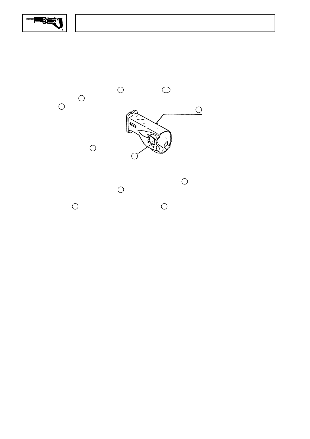
to position “Ι”, and remove the Insulation
and the Blade
forward (toward the
blade mounting end) .At
this time, be very
careful to avoid hooking
the portion marked
(see illustration right)
A
A
of the Insulation Cover
on the Change Lever.
Next, loosen the four M5 x 20 Hexagon Socket-Hd. Bolts
which secure the Upper Cover 18, and remove the Upper
Cover by lifting it upwards. At this time, t he rear end of
15
the Plunger
may strike the Gear Cover Ass’y 42. To
avoid this, the Plunger should be moved forward (toward the
Blade end) beforehand.
501
Insulation Cover
Fig. 4
, set the
38
16
−
−#
1
(2) Remove the Plunger from the Upper Cover:
36
Remove the two M5 Special Bolts
35
Connector
. As the Special Bolts are additionally
which secure the
secured by an adhesive agent (Cemedine 1500), it may be
18
necessary to heat the Upper Cover
15
Next, the Plunger
can be removed from the Upper Cover
to permit removal.
by pulling it out toward the front (toward t he blade end).
25
(3) Remove the Plunger Case Ass’y
First, remove the E-Type Retaining Ring
19
Lever
, and pull off the Change Lever from the Upper Cover.
from the Upper Cover:
26
from the Change
At this time, be very careful not to lose the D3. 969 Steel Ball
and Spring (C) 20 which may come out unexpectedly when the
Change Lever is turned.
22
Next, pull off the D6 Pin
from the Upper Cover. However,
as the D6 Pin is pressure fitted on the Upper Cover, be very
careful in its removal.
(4) Gear Cover Ass’y and Housing Ass’y Disassembly:
When the four M5 x 35
the Gear Cover Ass’y
53
Ass’y
can be removed. At this time, the Armature Ass’y
+
-Hd. Tapping Screws
42
, Inner Cover 59, and Housing
40
are loosened,
remains on the side of the Housing, however the Brush Cap
and Carbon Brush 51 must be removed prior to reassembly.
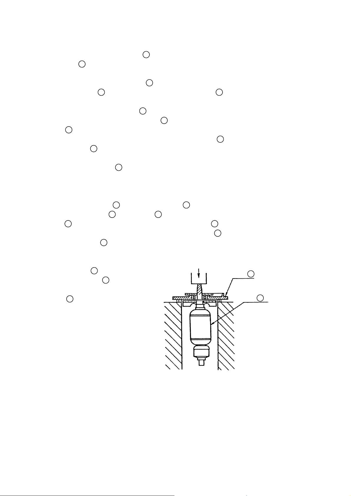
(5) Inner Cover and Armature Ass’y Disassembly:
First, remove the C-Type
54
Retaining Ring
the Armature Ass’y
from
60
.
Push
Then, support the Inner
59
Cover
as shown in the
illustration, and push
down on the Pinion end of
the Armature Ass’y with a
press to disassemble the
Armature Ass’y and the
Inner Cover. At this time,
be very careful not to
excessively spread the
C-Type Retaining Ring during removal.
Fig. 5
60
18
50
21
Inner
Cover
59
Armature
Ass·y
60
−#2 −
 Loading...