

Page 1
POWER TOOLS
TECHNICAL DATA
AND
SERVICE MANUAL
CIRCULAR SAWS
C 6SE, C 7SE
SPECIFICATIONS AND PARTS ARE SUBJECT TO CHANGE FOR IMPROVEMENT
LIST Nos. C 6SE: 0587
C 7SE: 0588
Sep. 1999
C
MODELS
C 6SE
C 7SE
C 6SE
C 7SE
Page 2
REMARK:
Throughout this TECHNICAL DATA AND SERVICE MANUAL, a symbol(s)
is(are) used in the place of company name(s) and model name(s) of our
competitor(s). The symbol(s) utilized here is(are) as follows:
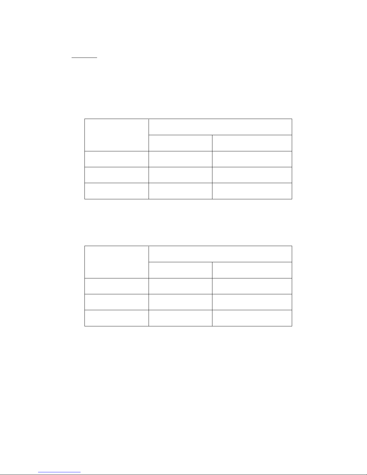
Symbol Utilized
Competitor
Company Name
Model Name
C --- 1 MAKITA
5606B
C 6SE
Symbol Utilized
Competitor
Company Name
Model Name
C --- 2 MAKITA
5806B
C 7SE
Page 3

Page
CONTENTS
[ Business Section ]
1. PRODUCT NAME
•••••••••••••••••••••••••••••••••••••••••••••••••••••••••••••••••••••••••••••••••••••••••••••••••••••••••••••••••••
1
2. MARKETING OBJECTIVE
••••••••••••••••••••••••••••••••••••••••••••••••••••••••••••••••••••••••••••••••••••••••••••••••••••••••••••
1
3. APPLICA TIONS
••••••••••••••••••••••••••••••••••••••••••••••••••••••••••••••••••••••••••••••••••••••••••••••••••••••••••••••••••••••••••
1
4. SELLING POINTS
•••••••••••••••••••••••••••••••••••••••••••••••••••••••••••••••••••••••••••••••••••••••••••••••••••••••••••••••••••••••
1
4-1. Selling Point Descriptions
•••••••••••••••••••••••••••••••••••••••••••••••••••••••••••••••••••••••••••••••••••••••••••••••••••••••
2
5. SPECIFICATIONS
•••••••••••••••••••••••••••••••••••••••••••••••••••••••••••••••••••••••••••••••••••••••••••••••••••••••••••••••••••••••
3
6. COMPARISONS WITH SIMILAR PRODUCTS
•••••••••••••••••••••••••••••••••••••••••••••••••••••••••••••••••••••••••••
4
7. PRECAUTIONS IN SALES PROMOTION
•••••••••••••••••••••••••••••••••••••••••••••••••••••••••••••••••••••••••••••••••••
4
7-1. Handling Instructions
••••••••••••••••••••••••••••••••••••••••••••••••••••••••••••••••••••••••••••••••••••••••••••••••••••••••••••••
4
[ Service Section ]
8. PRECAUTIONS IN DISASSEMBLY AND REASSEMBLY
••••••••••••••••••••••••••••••••••••••••••••••••••••••••••••
5
8-1. Disassembly
••••••••••••••••••••••••••••••••••••••••••••••••••••••••••••••••••••••••••••••••••••••••••••••••••••••••••••••••••••••••••
5
8-2. Reassembly
•••••••••••••••••••••••••••••••••••••••••••••••••••••••••••••••••••••••••••••••••••••••••••••••••••••••••••••••••••••••••••
6
8-3. Insulation Tests
••••••••••••••••••••••••••••••••••••••••••••••••••••••••••••••••••••••••••••••••••••••••••••••••••••••••••••••••••••••
10
8-4. Deflection of Saw Blade
••••••••••••••••••••••••••••••••••••••••••••••••••••••••••••••••••••••••••••••••••••••••••••••••••••••••••
10
8-5. Cleaning the Case
••••••••••••••••••••••••••••••••••••••••••••••••••••••••••••••••••••••••••••••••••••••••••••••••••••••••••••••••••
10
9. STANDARD REPAIR TIME (UNIT) SCHEDULES
••••••••••••••••••••••••••••••••••••••••••••••••••••••••••••••••••••••••
11
[ Appendix ]
Assembly Diagram for C 6SE
••••••••••••••••••••••••••••••••••••••••••••••••••••••••••••••••••••••••••••••••••••••••••••••••••••••••
12
Assembly Diagram for C 7SE
••••••••••••••••••••••••••••••••••••••••••••••••••••••••••••••••••••••••••••••••••••••••••••••••••••••••
16
Page 4
--- 1 ---
1. PRODUCT NAME
Hitachi Circular Saw, Model C 6SE [165 mm (6-1/2") ]
Hitachi Circular Saw, Model C 7SE [190 mm (7-1/2")]
2. MARKETING OBJECTIVE
The Models C 6SE and C 7SE have been developed based on the current Models C6 and C7. The key features
of the Models C 6SE and C 7SE are as follows:
(1) Double-insulated construction. No grounding required
(2) Power-plus heavy-duty motor
(3) High performance 40-tooth tungsten carbide tipped (TCT) saw blade as standard
(C 6SE: 165 mm, C 7SE: 190 mm)
(4) Improved operability with large front grip, large plastic wing bolt & nut for base adjustment, and large lever on
the safety cover
(5) Convenient cutting depth scale on the safety cover
3. APPLICA TIONS
Cutting of various wood materials
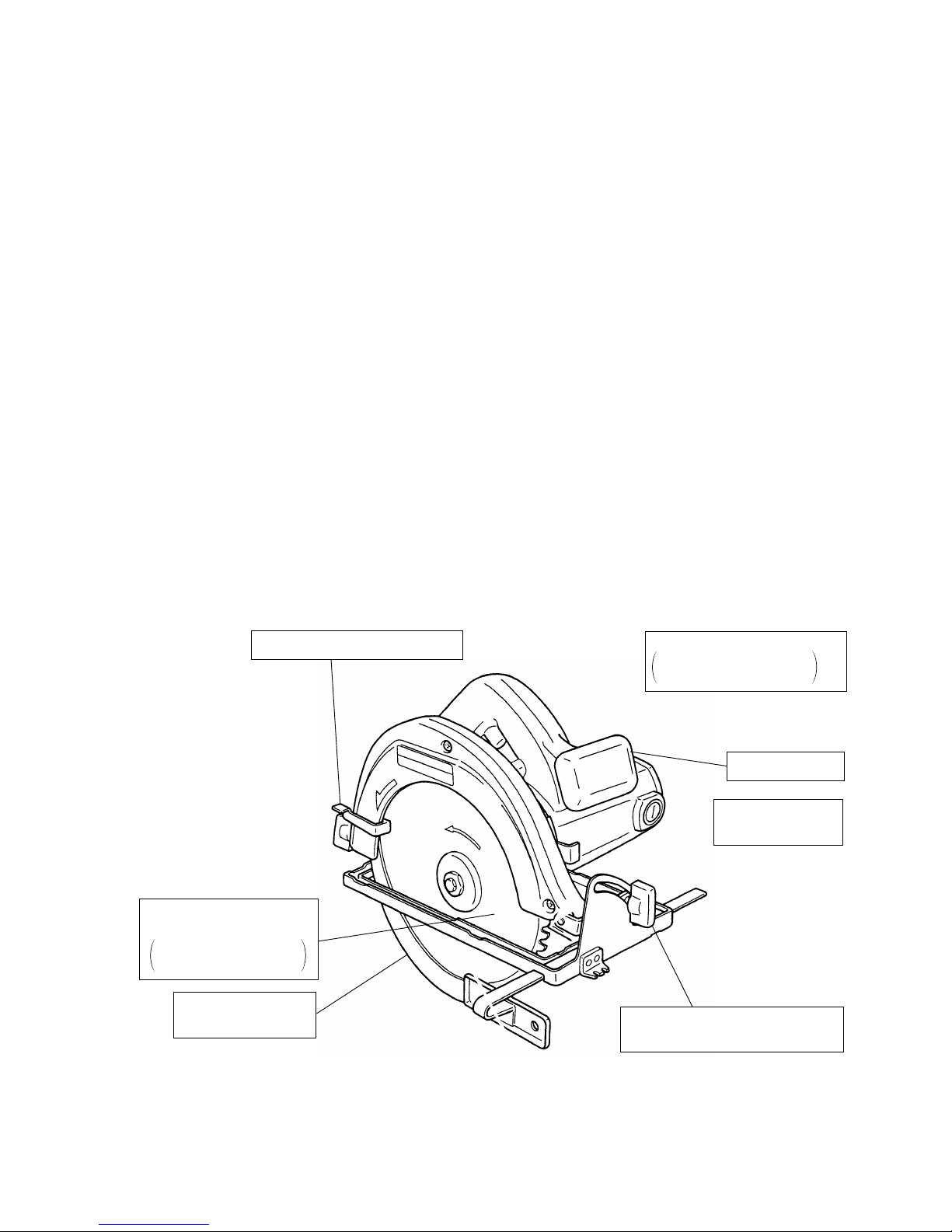
4. SELLING POINTS
Double-insulated
construction
Cutting depth scale
on the safety cover
Large front grip
High performance
40T TCT saw blade
C 6SE: 165 mm dia.
C 7SE: 190 mm dia.
Power-plus heavy duty motor
C 6SE: Input 960 W
C 7SE: Input 1,080 W
Large plastic wing bolt & nut for
easy base adjustment
Large lever on the safety cover
Page 5
--- 2 ---
4-1. Selling Point Descriptions
(1) Double-insulated construction
Grounding is not required because of the double-insulated construction.
(2) Power-plus heavy duty motor
Powerful motor provides greater input and output than those of the Models C6 and C7.
(3) High performance 40-tooth tungsten carbide tipped (TCT) saw blade as standard
High performance TCT saw blade (40 teeth) is provided as standard instead of the conventional combination
blade. The Models C 6SE and C 7SE provide greater maximum cutting depth than the conventional models
by using a 165 mm dia. TCT saw blade and a 190 mm dia. TCT saw blade respectively.
(4) Improved operability with large front grip, large plastic wing bolt & nut for base adjustment, and large lever on
the safety cover
The circular saw can be stably handled with both hands because the front grip is formed with the housing as
one piece. The inclination adjusting wing bolt and cutting depth adjusting wing nut were changed from steel to
plastic for better operability. A large safety cover knob is adopted for easier opening and closing of the safety
cover.
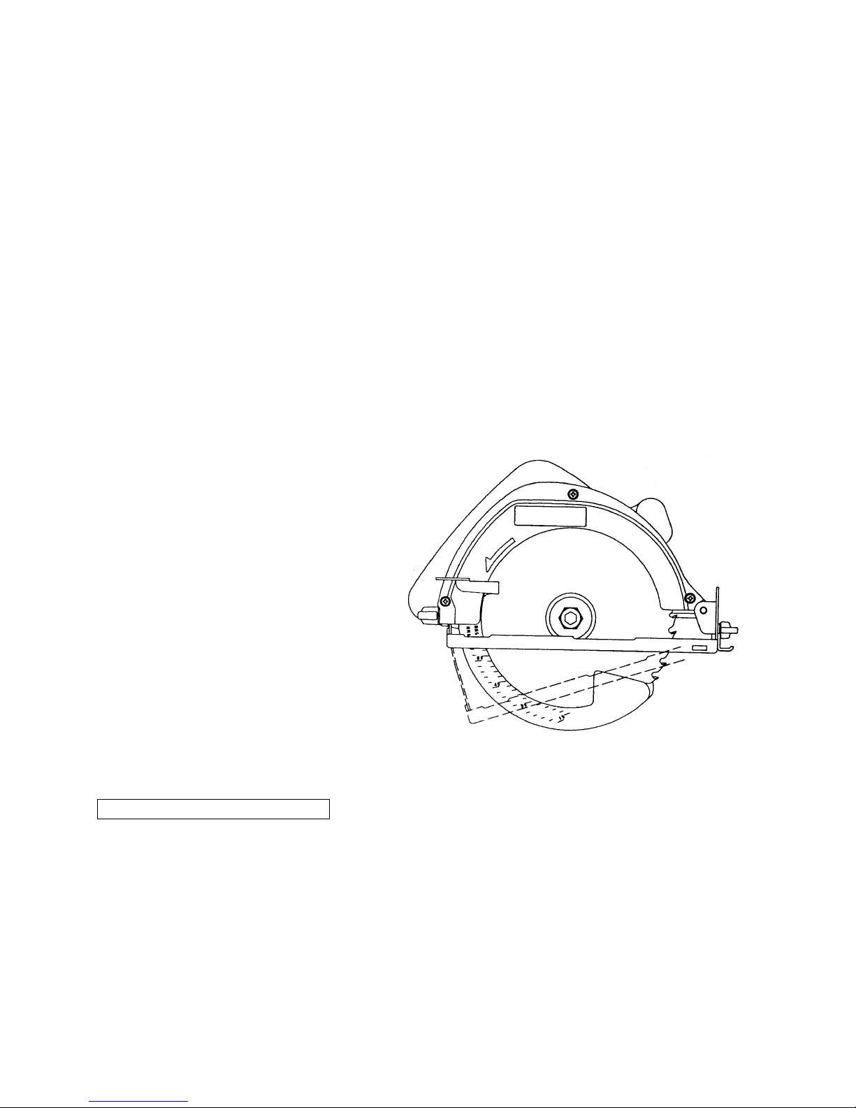
(5) Convenient cutting depth scale on the safety cover
A cutting depth scale is marked in millimeters on
the safety cover. By aligning the bottom of the
base with the scale, you can easily set the
desired cutting depth. The inner scale is for a
160 mm dia. saw blade on the C 6SE or for a
185 mm dia. saw blade on the C 7SE, and the
outer scale is for a 165 mm dia. saw blade on the
C 6SE or for a 190 mm dia. saw blade on the
C 7SE. Both scales are graduated in 3
millimeters. An example, when the cutting depth
is adjusted to 30 mm, is shown in Fig. 1.
Notes on using the cutting depth scale
• This scales should only be used as a rough guide. If more accurate adjustment is required, instruct the
customers to measure the saw blade tip directly from the bottom surface of the base.
• As the scale indicates a cutting depth when the saw blade is at a right angle to the base, it cannot be used
for inclined cutting.
Fig. 1
Page 6
--- 3 ---
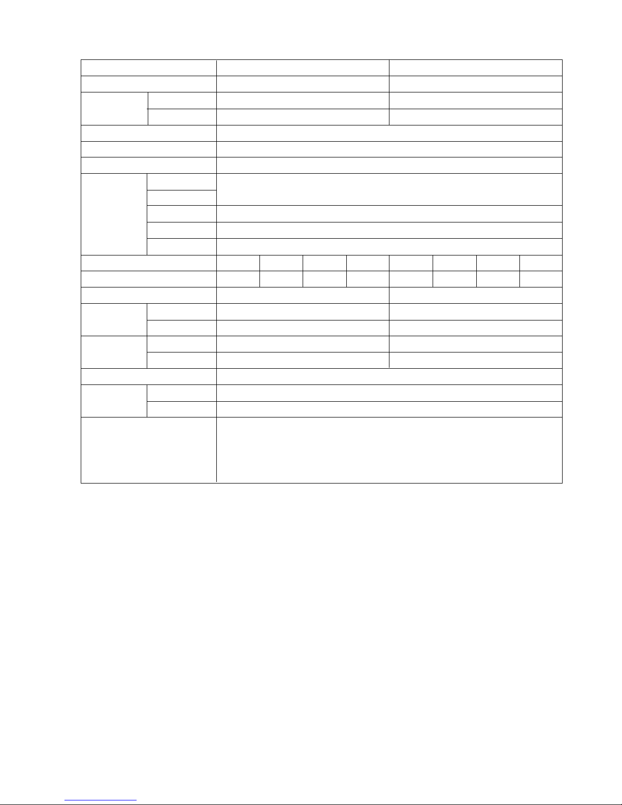
5. SPECIFICATIONS
Model
Saw blade diameter
Cutting depth
at 90˚
at 45˚
Power source
Type of motor
Type of switch
Housing
Handle cover
Enclosure Gear cover
Safety cover
Base
* Voltage (V)
* Current (A)
Power input
Rotation
No-load
speed
Full-load
Weight
Net
Gross
Packaging
Cord
Type
Overall length
Standard equipment
C 6SE C 7SE
165 mm (6-1/2") 190 mm (7-1/2")
0 --- 56 mm (0 --- 2-7/32") 0 --- 67 mm (0 --- 2-5/8")
Max. 37 mm (1-15/32") Max. 44 mm (1-23/32")
AC single phase 50/60 Hz
AC single phase commutator motor
Trigger switch
Polycarbonate resin
Cast aluminum
Sheet metal
Sheet metal
960 W 1,080 W
5,000 /min 5,000 /min
4,260 /min 3,900 /min
3.2 kg (7.1 lbs) 3.7 kg (8.2 lbs)
4.8 kg (10.6 lbs) 5.3 kg (11.7 lbs)
Corrugated cardboard box
Two core cabtire cable
2.5 m (8.2 ft.)
Tungsten carbide tipped (TCT) saw blade
•••••••••••••••••••••••••••••••••••••••••••••••••••
1
Box wrench
•••••••••••••••••••••••••••••••••••••••••••••••••••••••••••••••••••••••••••••••••••••••••••••••
1
Parallel guide
••••••••••••••••••••••••••••••••••••••••••••••••••••••••••••••••••••••••••••••••••••••••••••
1
Wing bolt
••••••••••••••••••••••••••••••••••••••••••••••••••••••••••••••••••••••••••••••••••••••••••••••••••
1
110 220 230 240 110 220 230 240
9.2 4.6 4.4 4.3 10.3 5.2 4.9 4.7
* Check the tool name plate to confirm the rating, as it is subject to change by area.
Page 7
--- 4 ---
Maker
Model
Saw blade diameter mm
Max. cutting
90˚ mm
depth
45˚ mm
Power input W
No-load rotation speed /min
Overall length mm
Weight kg
No-load rotation speed /min
Full-load rotation speed /min
Full-load output W
Max. output W
No-load noise dB
Insulation --Standard saw blade --Front grip or side handle --Material of wing bolt/nut --Scales on safety cover ---
Lmm
Hmm
Wmm
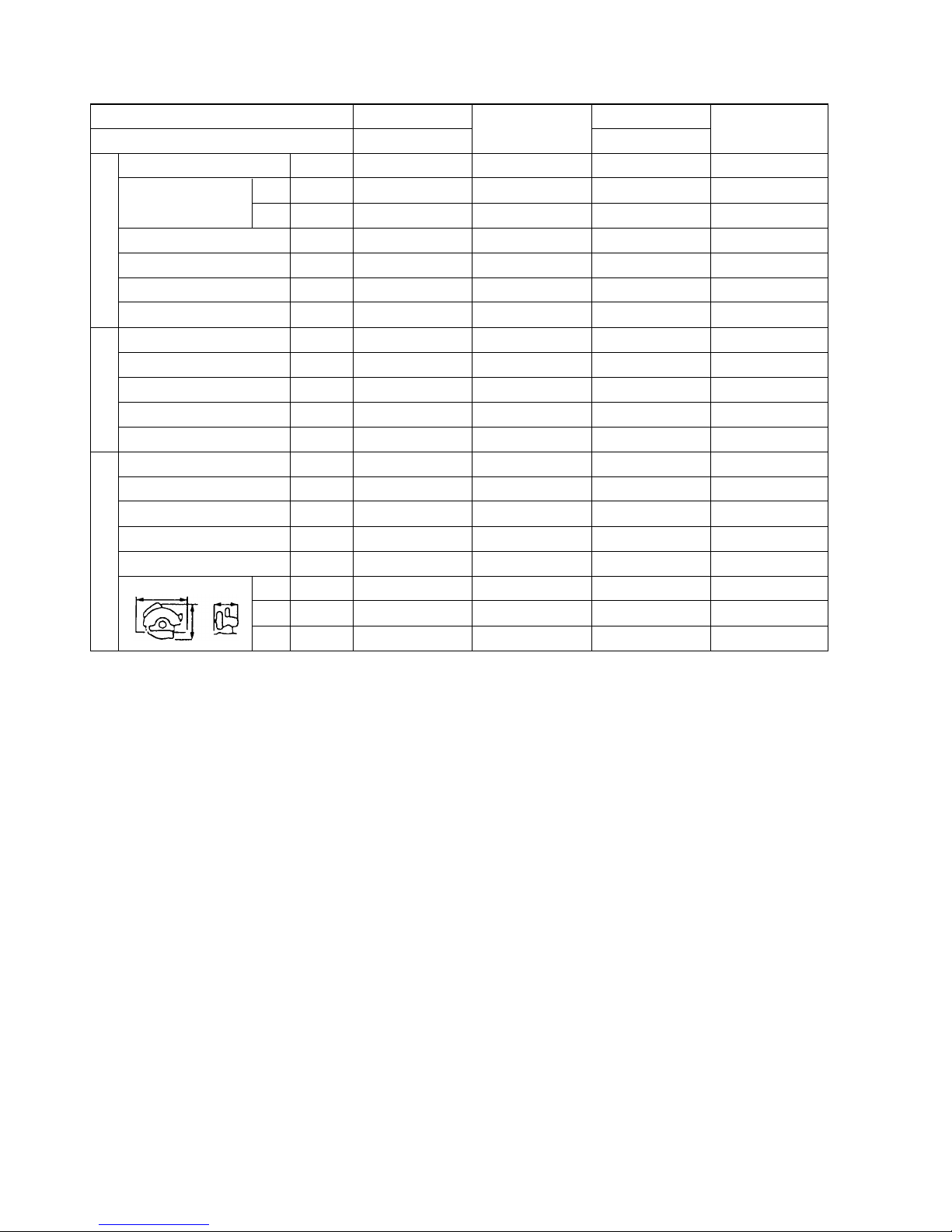
6. COMPARISONS WITH SIMILAR PRODUCTS
Catalog specifications
Characteristics*
Structure
HITACHI
C --- 1
HITACHI
C --- 2
C 6SE C 7SE
165 (6-1/2") 160 (6-1/4") 190 (7-1/2") 185 (7-1/4")
56 (2-7/32") 55 (2-5/32") 67 (2-5/8") 66 (2-19/32")
37 (1-15/32") 36 (1-3/8") 44 (1-23/32") 44 (1-23/32")
960 950 1,080 1,050
5,000 4,700 5,000 4,700
278 268 294 282
3.2 (7.1 lbs) 3.3 (7.3 lbs) 3.7 (8.2 lbs) 3.7 (8.2 lbs)
5,400 5,300 5,350 5,130
4,260 3,660 3,960 3,330
560 545 730 700
1,410 1,340 1,530 1,500
87 82 87 84
Double Double Double Double
TCT blade TCT blade TCT blade TCT blade
Provided Optional Provided Optional
Plastic Steel Plastic Steel
Provided None Provided None
278 268 294 282
224 230 241 240
218 225 221 230
L
W
H
7. PRECAUTIONS IN SALES PROMOTION
In the interest of promoting the safest and most efficient use of the Models C 6SE and C 7SE Circular Saws by all
of our customers, it is very important that at the time of sale the salesperson carefully ensures that the buyer
seriously recognizes the importance of the contents of the Handling Instructions.
7-1. Handling Instructions
Although every effort is made in each step of design, manufacture, and inspection to provide protection against
safety hazards, the dangers inherent in the use of any electric tool cannot be completely eliminated. Accordingly,
general precautions and suggestions for the use of electric power tools, and specific precautions and suggestions
for the use of the Circular Saw are listed in the Handling Instructions to enhance the safe and efficient use of the
tool by the customer. Salespersons must be thoroughly familiar with the contents of the Handling Instructions to
be able to offer appropriate guidance to the customer during sales promotion.
* Figures are based on 230 V motors
Page 8

--- 5 ---
8. PRECAUTIONS IN DISASSEMBLY AND REASSEMBLY
The disassembly and reassembly procedures for the Model C 6SE and C 7SE are essentially the same. The [ ]
numbers in descriptions below correspond to the item numbers in the parts list and exploded assembly diagram
for the Model C 6SE, and the < > numbers for the Model C 7SE. During disassembly and reassembly, and at all
times as well, sufficient care must be exercised in handling to ensure that there is no deviation in the flatness of
the bottom surface of the base and in its perpendicularity with relation to the saw blade.
8-1. Disassembly
Before disassembly, be sure to remove the TCT Saw Blade [14] <14> to
prevent damage to the teeth or personal injury.
(1) Removing the Safety Cover [6] <6>
Remove the Return Spring [7] <7> from the Safety Cover [6] <6>. Remove the three Machine Screws [11]
<10>, Bearing Cap [9] <9> and Safety Cover [6] <6>.
(2) Removing the Bearing Holder [4] <4>
Remove the two Seal Lock Flat Hd. Screws [5] <5> and remove the Bearing Holder [4] <4> together with the
Spindle and Gear Set [2] <2>.
(3) Removing the Spindle and Gear Set [2] <2>
Hold the Bearing Holder [4] <4> in a cylindrical jig with an inside diameter 49 mm, and remove the Spindle
and Gear Set [2] <2> from the Bearing Holder [4] <4> by pushing the end of the spindle.
(4) Removing the Armature [30] <29>
Loosen the Brush Cap [40] <39> and remove the two Carbon Brushes
[39] <38>.
Loosen and remove the three M5 x 45 Machine Screws [23] <22> to
separate the Housing Ass’y [25] <24> from the Gear Cover Ass’y [34]
<33>. The Armature [30] <29> can be removed by tapping around the
Housing Ass’y [25] <24> lightly with a wooden or plastic hammer. Be
careful not to tap the fan of the Armature [30] <29>.
(5) Removing the Base Ass’y [63] <62>
Remove the D6 x 30 Roll Pin [61] <60> to separate the Base Ass’y [63] <62> from the Gear Cover Ass’y [34]
<33>.
Fig. 2
Jig
Push
49 mm
60 mm
Page 9

--- 6 ---
8-2. Reassembly
Reassembly can be accomplished by following the disassembly procedures in reverse. However, particular
attention should be given to the following items.
(1) Tightening torquer for fastening screws and bolts
• M3 Machine Screws
•••••••••••••••••••••••••••••••••••••••••••••••••••••••••••••••••
0.8 0.2 N•m (8 2 kgf•cm)
• M4 Machine Screws
•••••••••••••••••••••••••••••••••••••••••••••••••••••••••••••••••
1.8 0.4 N•m (18 4 kgf•cm)
• M5 Machine Screws
•••••••••••••••••••••••••••••••••••••••••••••••••••••••••••••••••
3.4 0.7 N•m (35 7 kgf•cm)
• M7 x 17.5 Bolt [16] (16)
••••••••••••••••••••••••••••••••••••••••••••••••••••••••••••
9.8 2.0 N•m (100 20 kgf•cm)
• D4 Tapping Screws
••••••••••••••••••••••••••••••••••••••••••••••••••••••••••••••••••
2.0 0.5 N•m (20 5 kgf•cm)
• D5 Tapping Screws
••••••••••••••••••••••••••••••••••••••••••••••••••••••••••••••••••
2.9 0.5 N•m (30 5 kgf•cm)
• Brush Caps
••••••••••••••••••••••••••••••••••••••••••••••••••••••••••••••••••••••••••••••
0.98 0.5 N•m (10 5 kgf•cm)
• M4 x 10 Seal Lock Flat Hd. Screw
•••••••••••••••••••••••••••••••••••••••••••••
1.8 0.4 N•m (18 4 kgf•cm)
• M5 x 10 Seal Lock Flat Hd. Screw
•••••••••••••••••••••••••••••••••••••••••••••
3.4 0.7 N•m (35 7 kgf•cm)
• M3.5 Bind Screws
••••••••••••••••••••••••••••••••••••••••••••••••••••••••••••••••••••
0.6 0.15 N•m (6 1.5 kgf•cm)
• D4 FT Screws
••••••••••••••••••••••••••••••••••••••••••••••••••••••••••••••••••••••••••••
3.0 0.5 N•m (30 5 kgf•cm)
(2) Reassemble the Armature [30] <29>
Prior to assembling the Armature [30] <29>, ensure that the Bearing Lock [33] <32> is properly inserted into
the groove of the bearing case within the Gear Cover Ass'y [34] <33>.
(3) Reassemble the Lock Lever [31] <30> (See Fig. 3.)
A. Position the Lock Lever [31] <30> between the fan and the Ball Bearing [32] <31> of the Armature [30]
<29>, and carefully assemble it together with the Armature [30] <29> into the Gear Cover Ass'y [34] <33>.
B. Ensure that both ends of the spring on
the Lock Lever [31] <30> are properly
supported inside the ribs of the Gear
Cover Ass'y [34] <33>.
C. When assembly of the Lock Lever [31]
<30> has been completed (when the
Gear Cover Ass'y [34] <33> is
assembled to the Housing Ass'y [25]
<24> and fastened with the M5 x 45
Machine Screws [23] <22>), push the
Lock lever [31] <30> by hand and
ensure that it returns to its original
position when released.
[34] <33>
[31] <30>
[30] <29>
Rib
Fig. 3
Page 10

--- 7 ---
(4) Reassemble the Stator Ass'y [28] <27>
As shown in Fig. 4, insert a guide bar [J-132 stator press pins (Special repair tool, Code No. 970911) are
recommended] into the Stator Ass'y [28] <27> and the Housing Ass’y [25] <24> to accurately align the screw
hole on the Stator Ass'y [28] <27> with the corresponding hole on the Housing Ass’y [25] <24>. Press-fit the
Stator Ass'y [28] <27> into the Housing Ass’y [25] <24> so that the internal wire faces the Name Plate. Hook
the carbon brush terminals in the brush holders. Be careful not to put the internal wires in the ribs of the Stator
Ass'y [28] <27> in the Housing Ass’y [25] <24>. Fix the Stator Ass'y [28] <27> to the Housing Ass’y [25] <24>
with the two Hex. Hd. Tapping Screws [46] <45>. If the noise suppressor is provided, fix the Terminal [52]
<51> at the tip of the internal wire coming out of the noise suppressor with one of the two Hex. Hd. Tapping
Screws [46] <45>. (See Fig. 5.)
Guide bar
(J-132 stator
press pins)
[28] (27)
Brush holder
Name plate side
[25] <24>
[52] <51>
[46] <45>
Fig. 4
Fig. 5
Page 11

--- 8 ---
(5) Wiring
Wiring should be performed as shown below. Be careful not to sandwich the internal wires between the
Handle Cover [57] <56> and the Housing Ass'y [25] <24>.
1. Wiring diagram
[A] For Australia and New Zealand
Black or blue
Stator
Noise
suppressor
Switch
Blue
Power
source
Brown
Black or blue
Blue
Stator
Noise
suppressor
Switch
Blue
Power
source
Brown
Blue
Armature
Armature
Connector
Stator
Switch
Power
source
Black or brown
White, blue or black
Armature
Connector
White or blue
White, blue or black
[B] For Korea
[C] For other countries [ASEAN, M.E. Asia, Taiwan]
Page 12

--- 9 ---
[A] For Australia [B] For New Zealand
Blue
Black
Brown
Blue
Blue
Brown
[C] For Korea [D] For other countries [ASEAN, M.E. Asia, Taiwan]
Brown
Blue
Blue
Black or brown
White, blue
or black
White or blue
2. Schematic diagram
Page 13

--- 10 ---
(6) Lubrication
The Gear Cover Ass'y [34] <33>
•••••••••••••••••••
Apply Nippeco Grease (SEP-3A) 8 g
Code No. 930035
Amply rub grease into the teeth of gear and pinion.
8-3. Insulation Tests
On completion of disassembly and repair, measure the insulation resistance and conduct dielectric strength test.
Insulation resistance: 7MΩ or more with DC 500 V Megohm Tester
Dielectric strength: AC 4000 V/1 minute, with no abnormalities
8-4. Deflection of Saw Blade
Allowable deflection level of the saw blade shall be as follows.
8-5. Cleaning the Case
When the unit becomes soiled, clean it with a clean soft rag moistened with soapy water. Since chloric solvents,
gasoline and thinner tend to melt plastic material, their use for cleaning is absolutely avoided.
Model Measuring point Allowable level
C 6SE, C 7SE 150 0.5 mm max.
Page 14

--- 11 ---
9. STANDARD REPAIR TIME (UNIT) SCHEDULES
MODEL 10 20 30 40 50 60 min.
Fixed
Variable
Work Flow
Switch
Cord
Saw Blade
Safety Cover
Return Spring
Armature
Ball Bearing
(608VV)
Ball Bearing
(6000VV)
Gear Cover
Ass’y
Spindle and
Gear Set
Bearing Holder
Ball Bearing
x 2
Housing Ass’y
Stator Ass’y
General Assembly
Base Ass’y
C 6SE
C 7SE
Page 15

--- 12 ---
Assembly Diagram for C 6SE
Page 16

--- 13 ---
PARTS
C 6SE
: ALTERNATIVE PARTS
ITEM
NO.
CODE NO. DESCRIPTION
NO.
USED
REMARKS
1 606-ZZM BALL BEARING 606ZZC2PS2L 1
2 317-932 SPINDLE AND GEAR SET 1
3 873-095 O-RING (P-16) 1
4 941-048 BEARING HOLDER 1
5 990-430 SEAL LOCK FLAT HD. SCREW M4X10 2
6 317-930 SAFETY COVER 1
7 957-062 RETURN SPRING 1
8 620-2VV BALL BEARING 6202VVCMPS2L 1
9 941-049 BEARING CAP 1
10 949-451 SPRING WASHER M3 (10 PCS.) 3
11 949-203 MACHINE SCREW M3X8 (10 PCS.) 3
12 961-366 DISTANCE PIECE 1
* 13 993-598 WASHER (A) 1
* 13 315-968 WASHER (A) 1 FOR TPE
* 14 317-452 TCT SAW BLADE 165MM-D20 HOLE-NT40 1
* 14 317-937 TCT SAW BLADE 165MM-D25.4 HOLE-NT40 1 FOR TPE
15 957-064 WASHER (B) 1
16 957-749 BOLT (W/WASHER) M7X17.5 1
17 317-933 SAW COVER 1
18 HITACHI LABEL 1
19 949-219 MACHINE SCREW M4X16 (10 PCS.) 3
20 986-723 MACHINE SCREW (W/WASHERS) M4X8 1
21 301-653 TAPPING SCREW (W/FLANGE) D4X20 (BLACK) 2
22 961-732 TAIL COVER 1
23 302-434
MACHINE SCREW (W/WASHERS) M5X45 (BLACK)
3
* 24 NAME PLATE 1
* 25 317-935 HOUSING ASS’Y 1 INCLUD.36,38
* 25 317-936 HOUSING ASS’Y 1 INCLUD.36,38 FOR NZL
26 608-VVM BALL BEARING 608VVC2PS2L 1
27 930-703 BRUSH TERMINAL 2
* 28 340-447C STATOR ASS’Y 110V 1 INCLUD.27
* 28 340-447E STATOR ASS’Y 220V-230V 1 INCLUD.27
* 28 340-447F STATOR ASS’Y 240V 1 INCLUD.27
* 28 340-447G STATOR ASS’Y 220V-230V 1 INCLUD.27 FOR NZL,KOR
* 28 340-447H STATOR ASS’Y 240V 1 INCLUD.27 FOR AUS
29 987-980 FAN GUIDE 1
* 30 360-500C ARMATURE 110V 1
* 30 360-500E ARMATURE 220V-230V 1
* 30 360-500F ARMATURE 240V 1
31 987-981 LOCK LEVER 1
32 600-0VV BALL BEARING 6000VVCMPS2L 1
33 931-701 BEARING LOCK 1
34 317-931 GEAR COVER ASS’Y 1 INCLUD.33,47,48
* 35 500-455Z CORD 1 (CORD ARMOR D8.8)
* 35 930-054 CORD 1 (CORD ARMOR D10.1) FOR TPE
* 35 500-234Z CORD 1 (CORD ARMOR D8.8) FOR INA,KOR
* 35 500-423Z CORD 1 (CORD ARMOR D8.8) FOR SIN,KUW
* 35 500-439Z CORD 1 (CORD ARMOR D8.8) FOR NZL,AUS
36 938-477 HEX. SOCKET SET SCREW M5X8 2
37 307-028 TAPPING SCREW (W/FLANGE) D4X25 (BLACK) 4
38 957-051 BRUSH HOLDER 2
*
6
----
99
Page 17

--- 14 ---
PARTS
C 6SE
ITEM
NO.
CODE NO. DESCRIPTION
NO.
USED
REMARKS
39 999-043 CARBON BRUSH (1 PAIR) 2
40 935-829 BRUSH CAP 2
* 41 980-063 TERMINAL 2 FOR CORD
* 42 981-373 TUBE (D) 2 FOR CORD
* 43 953-327 CORD ARMOR D8.8 1
* 43 938-051 CORD ARMOR D10.1 1
44 937-631 CORD CLIP 1
45 984-750 TAPPING SCREW (W/FLANGE) D4X16 2
46 953-174 HEX. HD. TAPPING SCREW D5X55 2
47 961-729 CUSHION 1
48 949-794 FLAT HD. SCREW M6X20 (10 PCS.) 1
49 948-167 SUPER LOCK WASHER M6 2
* 50 980-063 TERMINAL 2 FOR NZL,KOR
* 51 981-373 TUBE (D) 2 FOR AUS
* 52 959-144 TERMINAL 50051 (10 PCS.) 1 FOR NOISE SUPPRESSOR
* 53 994-273 NOISE SUPPRESSOR 1 FOR NZL,AUS,KOR
* 54 305-499 MACHINE SCREW (W/WASHER) M3.5X6 4 EXCEPT FOR AUS
* 55 957-747 SWITCH (A) (1P SCREW TYPE) W/LOCK 1
* 55 302-470 SWITCH (C) (1P SCREW TYPE) W/O LOCK 1 FOR NZL
* 55 963-756Z SWITCH (2P PILLAR TYPE) W/SAFETY LOCK 1 FOR AUS
* 56 959-140 CONNECTOR 50091 (10 PCS.) 1 EXCEPT FOR NZL,AUS
57 302-320 HANDLE COVER 1
58 301-806 WING BOLT M6X15 1
59 947-859 LOCK SPRING 1
60 302-459 WING BOLT M6X17 1
61 949-515 ROLL PIN D6X30 (10 PCS.) 1
62 314-620 BOLT ASS’Y (SQUARE) M6X22 1 INCLUD.49
63 317-934 BASE ASS’Y 1 INCLUD.49,58-60,62
: ALTERNATIVE PARTS
*
6
----
99
Page 18

--- 15 ---
: ALTERNATIVE PARTS
*
STANDARD ACCESSORIES
C 6SE
ITEM
NO.
CODE NO. DESCRIPTION
NO.
USED
REMARKS
501 940-543 BOX WRENCH 10MM 1
502 316-106 GUIDE WITH WING BOLT AND SPRING 1
6
----
99
Printed in Japan
(990625 N)
OPTIONAL ACCESSORIES
ITEM
NO.
CODE NO. DESCRIPTION
NO.
USED
REMARKS
601 949-172 SAW BLADE (COMBINATION) 160MM-D19 HOLE 1
602 879-096 PLANER SAW BLADE 160MM-D19 HOLE 1
603 879-097 SAW BLADE 160MM-D19 HOLE FOR PLASTIC 1
604 879-098 SAW BLADE 160MM-D19 HOLE FOR ALUMINUM 1
605 939-156 CUT-OFF WHEELS 150MM (10 PCS.) 1
606 961-734 CORD HANGER 1
Page 19

--- 16 ---
Assembly Diagram for C 7SE
Page 20

--- 17 ---
PARTS
C 7SE
: ALTERNATIVE PARTS
ITEM
NO.
CODE NO. DESCRIPTION
NO.
USED
REMARKS
1 626-VVM BALL BEARING 626VVC2PS2L 1
2 317-925 SPINDLE AND GEAR SET 1
3 873-095 O-RING (P-16) 1
4 940-867 BEARING HOLDER 1
5 990-299 SEAL LOCK FLAT HD. SCREW M5X10 2
6 317-923 SAFETY COVER 1
7 957-062 RETURN SPRING 1
8 620-2VV BALL BEARING 6202VVCMPS2L 1
9 940-868 BEARING CAP 1
10 307-635 MACHINE SCREW (W/SP. WASHER) M4X10 3
11 986-723 MACHINE SCREW (W/WASHERS) M4X8 1
12 961-366 DISTANCE PIECE 1
* 13 993-598 WASHER (A) 1
* 13 315-968 WASHER (A) 1 FOR TPE
* 14 317-928 TCT SAW BLADE 190MM-D20 HOLE-NT40 1
* 14 317-929 TCT SAW BLADE 190MM-D25.4 HOLE-NT40 1 FOR TPE
15 957-064 WASHER (B) 1
16 957-749 BOLT (W/WASHER) M7X17.5 1
17 317-926 SAW COVER 1
18 HITACHI LABEL 1
19 949-219 MACHINE SCREW M4X16 (10 PCS.) 3
20 301-653 TAPPING SCREW (W/FLANGE) D4X20 (BLACK) 2
21 961-732 TAIL COVER 1
22 302-434
MACHINE SCREW (W/WASHERS) M5X45 (BLACK)
3
23 NAME PLATE 1
* 24 317-935 HOUSING ASS’Y 1 INCLUD.35,37
* 24 317-936 HOUSING ASS’Y 1 INCLUD.35,37 FOR NZL
25 608-VVM BALL BEARING 608VVC2PS2L 1
26 930-703 BRUSH TERMINAL 2
* 27 340-448C STATOR ASS’Y 110V 1 INCLUD.26
* 27 340-448E STATOR ASS’Y 220V-230V 1 INCLUD.26
* 27 340-448F STATOR ASS’Y 240V 1 INCLUD.26
* 27 340-448G STATOR ASS’Y 220V-230V 1 INCLUD.26 FOR NZL,KOR
* 27 340-448H STATOR ASS’Y 240V 1 INCLUD.26 FOR AUS
28 987-940 FAN GUIDE 1
* 29 360-501C ARMATURE 110V 1
* 29 360-501E ARMATURE 220V-230V 1
* 29 360-501F ARMATURE 240V 1
30 987-981 LOCK LEVER 1
31 600-1VV BALL BEARING 6001VVCMPS2L 1
32 931-701 BEARING LOCK 1
33 317-924 GEAR COVER ASS’Y 1 INCLUD.32,46,47
* 34 500-455Z CORD 1 (CORD ARMOR D8.8)
* 34 500-234Z CORD 1 (CORD ARMOR D8.8) FOR INA
* 34 500-423Z CORD 1 (CORD ARMOR D8.8) FOR SIN,KUW
* 34 500-439Z CORD 1 (CORD ARMOR D8.8) FOR NZL,AUS
* 34 930-054 CORD 1 (CORD ARMOR D10.1) FOR TPE
35 938-477 HEX. SOCKET SET SCREW M5X8 2
36 307-028 TAPPING SCREW (W/FLANGE) D4X25 (BLACK) 4
37 957-051 BRUSH HOLDER 2
38 999-043 CARBON BRUSH (1 PAIR) 2
*
6
----
99
Page 21

--- 18 ---
PARTS
C 7SE
ITEM
NO.
CODE NO. DESCRIPTION
NO.
USED
REMARKS
39 935-829 BRUSH CAP 2
* 40 980-063 TERMINAL 2 FOR CORD
* 41 981-373 TUBE (D) 2 FOR CORD
* 42 953-327 CORD ARMOR D8.8 1
* 42 938-051 CORD ARMOR D10.1 1
43 937-631 CORD CLIP 1
44 984-750 TAPPING SCREW (W/FLANGE) D4X16 2
45 961-501 HEX. HD. TAPPING SCREW D5X60 2
46 961-729 CUSHION 1
47 949-794 FLAT HD. SCREW M6X20 (10 PCS.) 1
48 948-167 SUPER LOCK WASHER M6 2
* 49 980-063 TERMINAL 2 FOR NZL,KOR
* 50 981-373 TUBE (D) 2 FOR AUS
* 51 959-144 TERMINAL 50051 (10 PCS.) 1 FOR NOISE SUPPRESSOR
* 52 994-273 NOISE SUPPRESSOR 1 FOR NZL,AUS,KOR
* 53 305-499 MACHINE SCREW (W/WASHER) M3.5X6 4 EXCEPT FOR AUS
* 54 957-747 SWITCH (A) (1P SCREW TYPE) W/LOCK 1
* 54 302-470 SWITCH (C) (1P SCREW TYPE) W/O LOCK 1 FOR NZL
* 54 963-756Z SWITCH (2P PILLAR TYPE) W/SAFETY LOCK 1 FOR AUS
* 55 959-140 CONNECTOR 50091 (10 PCS.) 1 EXCEPT FOR NZL,AUS
56 302-320 HANDLE COVER 1
57 301-806 WING BOLT M6X15 1
58 947-859 LOCK SPRING 1
59 302-459 WING BOLT M6X17 1
60 949-515 ROLL PIN D6X30 (10 PCS.) 1
61 314-620 BOLT ASS’Y (SQUARE) M6X22 1 INCLUD.48
62 317-927 BASE ASS’Y 1 INCLUD.48,57-59,61
: ALTERNATIVE PARTS
*
6
----
99
Page 22

--- 19 ---
: ALTERNATIVE PARTS
*
STANDARD ACCESSORIES
C 7SE
ITEM
NO.
CODE NO. DESCRIPTION
NO.
USED
REMARKS
501 940-543 BOX WRENCH 10MM 1
502 316-106 GUIDE WITH WING BOLT AND SPRING 1
6
----
99
Printed in Japan
(990625 N)
OPTIONAL ACCESSORIES
ITEM
NO.
CODE NO. DESCRIPTION
NO.
USED
REMARKS
601 940-878 SAW BLADE (COMBINATION) 185MM-D19 HOLE 1
602 879-099 SAW BLADE (RIP) 185MM-D19 HOLE-NT36 1
603 879-101 PLANER SAW BLADE 185MM-D19 HOLE 1
604 879-100 SAW BLADE 185MM-D19 HOLE FOR PLASTIC 1
605 879-102 SAW BLADE 185MM-D19 HOLE FOR ALUMINUM 1
606 939-156 CUT-OFF WHEELS 150MM (10 PCS.) 1
607 961-734 CORD HANGER 1
 Loading...