

Page 1
Dustless Circular Saw
Model C 5YC
Handling Instructions
Note:
Before using this Electric Power Tool, carefully read through these
HANDLING INSTRUCTIONS to ensure efficient, safe operation. It is
recommended that these INSTRUCTIONS be kept readily available
as an important reference when using this power tool.
Page 2

2
GENERAL OPERATIONAL PRECAUTIONS
WARNING! When using electric tools, basic safety
precautions should always be followed to reduce the
risk of fire, electric shock and personal injury, including
the following.
Read all these instructions before operating this product
and save these instructions.
For safe operations:
1. Keep work area clean. Cluttered areas and benches
invite injuries.
2. Consider work area environment. Do not expose
power tools to rain. Do not use power tools in
damp or wet locations. Keep work area well lit.
Do not use power tools where there is risk to cause
fire or explosion.
3. Guard against electric shock. Avoid body contact
with earthed or grounded surfaces. (e.g. pipes,
radiators, ranges, refrigerators).
4. Keep children and infirm persons away. Do not let
visitors touch the tool or extension cord. All visitors
should be kept away from work area.
5. Store idle tools. When not in use, tools should be
stored in a dry, high or locked up place, out of reach
of children and infirm persons.
6. Do not force the tool. It will do the job better and
safer at the rate for which it was intended.
7. Use the right tool. Do not force small tools or
attachments to do the job of a heavy duty tool. Do
not use tools for purposes not intended; for example,
do not use circular saw to cut tree limbs or logs.
8. Dress properly. Do not wear loose clothing or
jewelry, they can be caught in moving parts. Rubber
gloves and non-skid footwear are recommended
when working outdoors. Wear protecting hair
covering to contain long hair.
9. Use eye protection. Also use face or dust mask if
the cutting operation is dusty.
10. Connect dust extraction equipment.
If devices are provided for the connection of dust
extraction and collection facilities ensure these are
connected and properly used.
11. Do not abuse the cord. Never carry the tool by the
cord or yank it to disconnect it from the receptacle.
Keep the cord away from heat, oil and sharp edges.
12. Secure work. Use clamps or a vise to hold the work.
It is safer than using your hand and it frees both
hands to operate tool.
13. Do not overreach. Keep proper footing and balance
at all times.
14. Maintain tools with care. Keep cutting tools sharp
and clean for better and safer performance. Follow
instructions for lubrication and changing
accessories. Inspect tool cords periodically and if
damaged, have it repaired by authorized service
center. Inspect extension cords periodically and
replace, if damaged. Keep handles dry, clean, and
free from oil and grease.
15. Disconnect tools. When not in use, before servicing,
and when changing accessories such as blades,
bits and cutters.
16. Remove adjusting keys and wrenches. Form the
habit of checking to see that keys and adjusting
wrenches are removed from the tool before turning
it on.
17. Avoid unintentional starting. Do not carry a pluggedin tool with a finger on the switch. Ensure switch is
off when plugging in.
18. Use outdoor extension leads. When tool is used
outdoors, use only extension cords intended for
outdoor use.
19. Stay alert. Watch what you are doing. Use common
sense. Do not operate tool when you are tired.
20. Check damaged parts. Before further use of the
tool, a guard or other part that is damaged should
be carefully checked to determine that it will operate
properly and perform its intended function. Check
for alignment of moving parts, free running of
moving parts, breakage of parts, mounting and any
other conditions that may affect its operation. A
guard or other part that is damaged should be
properly repaired or replaced by an authorized
service center unless otherwise indicated in this
handling instructions. Have defective switches
replaced by an authorized service center. Do not
use the tool if the switch does not turn it on and off.
21. Warning
The use of any accessory or attachment, other than
those recommended in this handling instructions,
may present a risk of personal injury.
22. Have your tool repaired by a qualified person.
This electric tool is in accordance with the relevant
safety requirements. Repairs should only be carried
out by qualified persons using original spare parts.
Otherwise this may result in considerable danger
to the user.
PRECAUTIONS ON USING CIRCULAR SAW
1. Do not use saw blades which are deformed or
cracked.
2. Do not use saw blades made of high speed steel.
3. Do not use saw blades which do not comply with
the characteristics specified in these instructions.
4. Do not stop the saw blades by lateral pressure on
the side surface of disc.
5. Always keep the saw blade sharp.
6. Ensure that the lower guard moves smoothly and
freely.
7. Never use the circular saw with its lower guard
fixed in the open position.
8. Ensure that the retraction mechanism of the guard
system operates accurately.
9. Never operate the circular saw with grasping the
saw blade upside down or to the lateral direction.
10. Ensure that the material is free of foreign matters
such as nails.
11. For model C5YC, the saw blade’s diameters which
can be mounted are 125 mm or less.
12. Be careful of brake kickbac.
This circular saw incorporates an electric brake that
functions when the switch is released. As there is
some kickback when the brake functions, be sure to
hold the main body securely.
Page 3
3
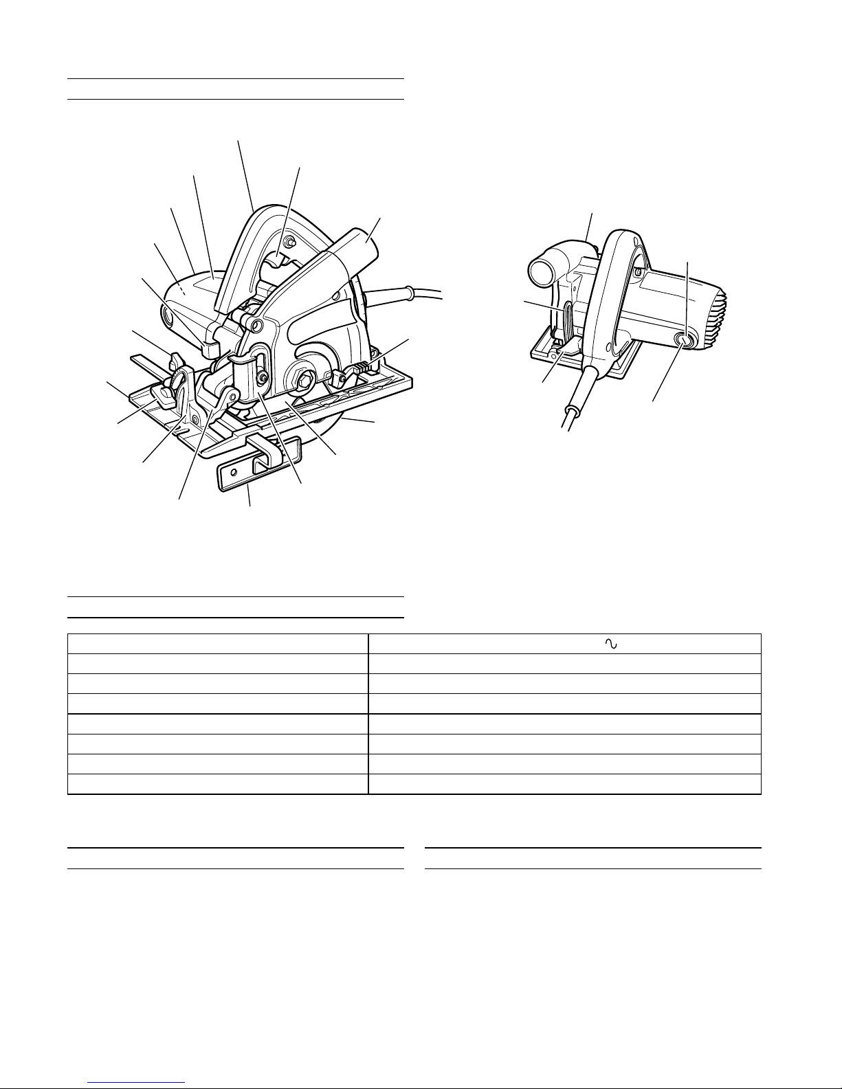
NAME OF PARTS
SPECIFICATIONS
Voltage (by areas)* (230 V, 240 V)
Cutting Depth 35 mm Max.
Power Input* 1010 W
Capacity 125 mm Max. Hole diam. 20 mm
Full Load Amp.* 4.7 A, 4.6 A
Dimensions (Length × Height × Width) 284 mm × 208 mm × 320 mm
No Load Speed 9600/min
Weight (without cord) 2.9 Kg
STANDARD ACCESSORIES
(1) Box wrench ............................................................... 1
(2) Guide .......................................................................... 1
(3) Dust bag .................................................................... 1
Standard accessories are subject to change without
notice.
OPTIONAL ACCESSORIES (sold separately)
䡬 Carbide Tipped Saw Blade (Dia. 125 mm) for the
gypsum board.
Optional accessories are subject to change without
notice.
Handle
Switch
Saw cover
Lever
Lower guard
Saw blade
Slide cover
Guide
Bevel piece
Inclined gauge
Wing bolt
Lock lever
Motor
Housing
Name plate
Gear cover
Brush holder
Brush cap
Clamp lever
Link
Wing bolt
Base
* Be sure to check the nameplate on product as it is subject to change by areas.
Page 4
4
APPLICATION
(1) Cutting the hard boards types T9 and T7.
(ex. harditex, hardiflex, etc.)
(2) Cutting the gypsum board.
PRIOR TO OPERATION
1. Power source
Ensure that the power source to be utilized conforms
to the power requirements specified on the product
nameplate.
2. Power switch
Ensure that the power switch is in the OFF position.
If the plug is connected to a receptacle while the
power switch is in the ON position, the power tool
will start operating immediately, which could cause
a serious accident.
3. Extension cord
When the work area is removed from the power
source, use an extension cord of sufficient thickness
and rated capacity. The extension cord should be
kept as short as practicable.
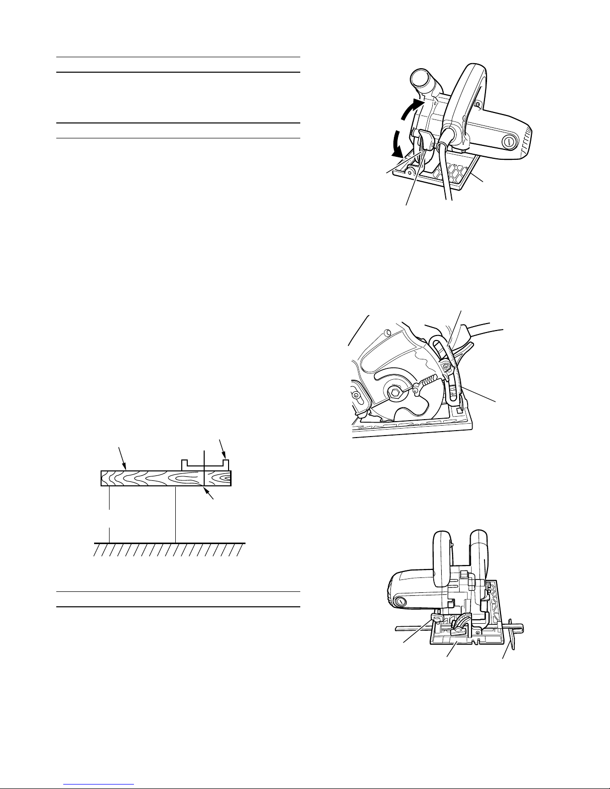
4. Prepare a wooden workbench (Fig. 1)
Since the saw blade will extend beyond the lower
surface of the lumber, place the lumber on the
workbench prior to cutting. If a square block is
utilized as the workbench, adjust leveling to ensure
that it is properly stabilized. An unstable workbench
will result in hazardous operation.
CAUTION
● To avoid possible accident, remains always ensure
that the portion of workpiece after cutting is securely
anchored or held in position.
Fig. 1
ADJUSTING THE SAW PRIOR TO USE
1. Adjusting the cutting depth (Fig. 2)
CAUTION
If the clamp lever is loose, injury can result.
Tighten it securely after adjustment.
To adjust cutting depth, loosen the clamp lever and,
while holding the base with one hand, move the
main body up and down to obtain the prescribed
cutting depth. After adjusting to the prescribed
cutting depth, tighten the clamp lever securely.
Fig. 2
(2) When a base and saw blade are right-angled, it cuts
deeply using the scale of a link part, and the depth
can be adjusted (Fig. 3).
Fig. 3
3. Regulating the guide (Fig. 4)
The cutting position can be regulated by moving
the guide to the left or right after loosening its
wing-bolt. The guide may be mounted on either the
right or left side of the base.
Fig. 4
Loosen
Tighten
Link
Clamp lever
Base
Workpiece
Base
Workbench
Saw blade
Link
Scale link
Wing bolt
Base Guide
Page 5

5
CUTTING PROCEDURES
CAUTION
䡬 During use, when the body is out of condition or there
is unusual sound, please turn off a switch immediately.
䡬 During cutting, please do not pry the body or do not
push too much strongly. Please carry forward the
body calmly straightly.
It becomes the cause of an injury in response to
restitution. Moreover, while unreasonableness starts
a motor part, the life of saw blade is shortened.
䡬 Please do not carry out usage which made saw blade
facing up and sideways.
It becomes the cause of an injury.
䡬 Please use protection glasses.
䡬 Please use the protection implement of an ear.
䡬 Surely, the time of work discontinuation and after
work should turn off and put a switch, and should
pull out a lump plug from a power supply wall socket.
䡬 Be careful by rotating saw blade not to cut a code.
NOTE
䡬 Before beginning cutting, rotation of saw blade should
become the maximum high speed.
䡬 Extrusion fabrication cement building materials
should not cut 1 time of the cut depth with the speed
of 40 cm or less in 20 mm or less and 1 minute.
When using the cut depth, making it shallow, in order
that edge of a blade may open, dust-collecting power
declines.
1. The body (base) is carried on work piece and guide
slot of the base front part is united with a premarked
line.
When you do not incline, please follow large guide
slot as a guide, and when you incline (45°), follow
small guide slot as a guide (Fig. 5, Fig. 6, Fig. 7).
(It is the figure seen from the top)
Fig. 5
(When not inclined)
Fig. 6
(When inclined 45°)
Fig. 7
2. Saw blade turns on a switch in the state where work
piece cannot be touched.
This state is maintained until it carries forward the
body ahead slowly and finishes cutting it then.
For pulling and cleaning the skin, it advances straightly
with fixed speed.
MOUNTING AND DISMOUNTING THE SAW
BLADE
As for this body, saw blade is not attached to the body at
the time of factory shipments.
Please carry out attachment and removal of saw blade in
the following procedure in the case of use.
CAUTION
䡬 Surely, please turn off and put a switch in the case of
attachment and removal of saw blade, and pull out a
lump plug from a power supply wall socket.
It becomes the basis of the unexpected accident.
䡬 Attachment and detachment of a hexagonal flange
bolt should work with an attached box spanner.
If tools other than attachment are used, it will become
past [a bundle] and the shortage of bolting, and will
become the cause of an injury.
When not
inclined
Premarked line Work piece
Large guide slot
Small guide slot
When inclined 45°
Wing bolt
Guide
Cutting position
(in the case of 45°)
Wing bolt
Inclination scale
Page 6

6
1. How to attach (Fig. 8)
(1) The cut depth is made into the minimum.
A lever is loosened, a base is made into the minimum
cut depth, and a lever is fastened.
Fig. 8
(2) Two projection parts of a slide cover are pressed
down with a finger, and it moves up (Fig. 9).
Fig. 9
(3) A washer (A) is removed (Fig. 10).
Pushing in a lock lever, a hexagonal flange bolt is
loosened with an attached box spanner, and a washer
(A) is removed.
Since a hexagonal flange bolt is a left screw, it will
loosen, if it turns clockwise.
After removing, the garbage adhering to the spindle
or the washer (A) is often wiped off.
Fig. 10
(4) Saw blade is attached (Fig. 11)
A lower guard is carried out to full open, and saw
blade is attached.
It is made in agreement [the direction of an arrow of
saw blade] with the direction of an arrow of saw
cover.
Fig. 11
(5) A hexagonal flange bolt is tightened (Fig. 12).
A washer (A) and a hexagonal flange bolt are attached
in order of the left figure, and a hexagonal flange bolt
is fully bound tight using an attached box spanner,
pushing a lock lever.
Fig. 12
USE OF DUST BAG
CAUTION
䡬 To avoid serious accident, ensure the switch is
in the OFF position, and disconnect the plug from
the receptacle.
䡬 Never attempt to saw any material like metal and
so on that give off sparks. Such action can lead
to fire or injury.
1. Mounting the dust bag
Hold the clasp of the dust bag and insert it into
the adapting mouth of the body while opening the
thrusting mouth (Fig. 13).
Loosens
Tighten
Base
Clamp lever
Lever
Saw blade
Lower guard
Loosens
A hexagonal flange
bolt is turned with
a box spanner
A lock lever is
pushed in
Tighten
Projection part
Slide cover
Saw blade
Spindle
Hexagonal flange boIt
Washer (A)
Washer (B)
Page 7

7
Fig. 13
2. Dumping sawdust and cleaning the inside of dust
bag
NOTE
䡬 If too much sawdust is accumulated inside the
dust bag, the dust collector will run low on
power. Attempt to dump the sawdust as early
as you can and clean the dust bag thoroughly
so that you can enjoy your work with strong dust
collecting power.
(1) Hold the clasp, open the thrusting mouth of the
dust bag, and pull it off from the body.
(2) Open the fastener (Fig. 14) and dump the sawdust.
Fig. 14
MAINTENANCE AND INSPECTION
1. Inspecting the saw blade
Since use of a dull saw blade will degrade efficiency
and cause possible motor malfunction. Resharpen and
replace the saw blade as soon as abrasion is noted.
2. Inspecting the mounting screws
Regularly inspect all mounting screws and ensure
that they are properly tightened. Should any of the
screws be loose, retighten them immediately. Failure
to do so could result in serious hazard.
3. Maintenance of the motor
The motor unit winding is the very “heart” of the
power tool.
Exercise due care to ensure the winding does not
become damaged and/or wet with oil or water.
4. Inspecting the carbon brushes
For your continued safety and electrical shock
protection, carbon brush inspection and replacement
on this tool should ONLY be performed by a Hitachi
Authorized Service Center.
5. Replacing supply cord
If the supply cord of Tool is damaged, the Tool
must be returned to Hitachi Authorized Service
Center for the cord to be replaced.
6. Adjusting the base and saw blade to maintain
perpendicularity
The angle between the base and the saw blade has
been adjusted to 90°, however should this
perpendicularity be lost for some reason, adjust in
the following manner:
(1) Placing a square against the base of the tool,
determine the angle desired and lightly tighten the
M4 screw (See Fig. 15).
(2) Turn the angle adjustment screw until the end of
the screw touches the bevel plate (See Fig. 4).
(3) After all adjustments have been made, firmly tighten
the M4 screw.
(For inclination adjustment)
Fig. 15
7. Service parts list
CAUTION
Repair, modification and inspection of Hitachi Power
Tools must be carried out by a Hitachi Authorized
Service Center.
Especially laser device should be maintained by the
authorized agent by laser manufacturer.
Always assign the repair of laser device to Hitachi
Authorized Service Center.
This Parts List will be helpful if presented with the
tool to the Hitachi Authorized Service Center when
requesting repair or other maintenance.
In the operation and maintenance of power tools, the
safety regulations and standards prescribed in each
country must be observed.
MODIFICATIONS
Hitachi Power Tools are constantly being improved
and modified to incorporate the latest technological
advancements.
Accordingly, some parts may be changed without
prior notice.
NOTE
Due to HITACHI’s continuing program of research and
development, the specifications herein are subject to
change without prior notice.
Dust bag
Adapting mouth
Clasp
Fastener
Square
Wing bolt
Slotted set screw
Base
Page 8

8
Page 9

9
ITEM
NO.
PART NAME
1SAW COVER
2 BOLT (LEFT HAND) W/WASHER M7 × 17.5
3WASHER (A)
4WASHER (B)
5 DUST WASHER
6 O-RING (1AP-20)
7 MACHINE SCREW (W/WASHER) M4 × 14
8 RETAINING RING FOR D30 SHAFT
9 LEVER
10 RETURN SPRING
11 LOWER GUARD
12 SEAL LOCK FLAT HD. SCREW M4 × 14
13 BEARING HOLDER
14 SLEEVE
15 BALL BEARING 6094DDPS2L
16 SPINDLE AND GEAR SET
17 BALL BEARING 606ZZC2PS2L
18 MACHINE SCREW M4 × 8
19 GEAR COVER
20 SPACER
21 MACHINE SCREW M4 × 10
22 LED CASE (D)
23 MACHINE SCREW (W/SP. WASHERS) M4 × 20
24 PINION
25 BALL BEARING 629VVC2PS2L
26 RUBBER RING
27 LOCK LEVER
28 ARMATURE
29 FAN GUIDE
30 HEX. HD. TAPPING SCREW D5 × 65
31 STATOR ASSAY
32 BRUSH TERMINAL
33 FLAT HD. SCREW M5 × 20
34 CUSHION
35 DEPTH LIMITED
36 CLEAR COVER
37 WASHER (A)
38 BALL BEARING 608VVC2PS2L
39 HOUSING ASSAY
40 TAPPING SCREW (W/FLANGE) D4 × 20
41 NAME PLATE
42 MACHINE SCREW (W/SP. WASHERS) M5 × 35
43 BASE ASSAY
44 ROLL PIN D& × 45
45 WING BOLT M6 × 16.5
46 LOCK SPRING
ITEM
NO.
PART NAME
47 SUPER LOCK WASHER M6
48 WING BOLT (A)
49 HANDLE COVER
50 SWITCH
51 SLOTTED HD. SET SCREW (SEAL LOCK) M6 × 6
52 BOLT WASHER M8
53 LOCK BOLT M8
54 LOCK LEVER
55 MACHINE SCREW (W/SP.WASHERS) M4 × 12
56 TAPPING SCREW (W/WASHER) D4 × 16
57 CORD CLIP
58 CORD
59 CORD ARMOR
60 BRUSH CAP
61 CARBON BRUSH
62 BRUSH HOLDER
63 HEX. SOCKET SET SCREW M5 × 8
501 GUIDE
502 BOX WRENCH 10MM
503 DUST BAG
504 SPACER
Page 10

10
Page 11

11
Page 12

505
Code No. C99120611 N
Printed in Japan
Hitachi Koki Co., Ltd.
 Loading...