

Page 1
Cordless Circular Saw
Model C 18DBL
Handling instructions
Note:
Before using this Power Tool, carefully read through these
HANDLING INSTRUCTIONS to ensure efficient, safe operation. It is
recommended that these INSTRUCTIONS be kept readily available
as an important reference when using this power tool.
Page 2

GENERAL POWER TOOL SAFETY WARNINGS
WARNING
Read all safety warnings and all instructions.
Failure to follow the warnings and instructions may result
in electric shock, fire and/or serious injury.
Save all warnings and instructions for future reference.
The term “power tool” in the warnings refers to your
mains-operated (corded) power tool or battery-operated
(cordless) power tool.
1) Work area safety
a) Keep work area clean and well lit.
Cluttered or dark areas invite accidents.
b) Do not operate power tools in explosive
atmospheres, such as in the presence of
flammable liquids, gases or dust.
Power tools create sparks which may ignite the
dust or fumes.
c) Keep children and bystanders away while
operating a power tool.
Distractions can cause you to lose control.
2) Electrical safety
a) Power tool plugs must match the outlet.
Never modify the plug in any way.
Do not use any adapter plugs with earthed
(grounded) power tools.
Unmodified plugs and matching outlets will
reduce risk of electric shock.
b) Avoid body contact with earthed or grounded
surfaces, such as pipes, radiators, ranges and
refrigerators.
There is an increased risk of electric shock if
your body is earthed or grounded.
c) Do not expose power tools to rain or wet
conditions.
Water entering a power tool will increase the
risk of electric shock.
d) Do not abuse the cord. Never use the cord for
carrying, pulling or unplugging the power tool.
Keep cord away from heat, oil, sharp edges or
moving parts.
Damaged or entangled cords increase the risk
of electric shock.
e) When operating a power tool outdoors, use an
extension cord suitable for outdoor use.
Use of a cord suitable for outdoor use reduces
the risk of electric shock.
f) If operating a power tool in a damp location
is unavoidable, use a residual current device
(RCD) protected supply.
Use of an RCD reduces the risk of electric shock.
3) Personal safety
a) Stay alert, watch what you are doing and use
common sense when operating a power tool.
Do not use a power tool while you are tired or
under the influence of drugs, alcohol or medication.
A moment of inattention while operating power
tools may result in serious personal injury.
b) Use personal protective equipment. Always wear
eye protection.
Protective equipment such as dust mask, nonskid safety shoes, hard hat, or hearing protection
used for appropriate conditions will reduce
personal injuries.
1
c) Prevent unintentional starting. Ensure the switch
is in the off position before connecting to power
source and/or battery pack, picking up or
carrying the tool.
Carrying power tools with your finger on the
switch or energising power tools that have the
switch on invites accidents.
d) Remove any adjusting key or wrench before
turning the power tool on.
A wrench or a key left attached to a rotating part
of the power tool may result in personal injury.
e) Do not overreach. Keep proper footing and
balance at all times.
This enables better control of the power tool in
unexpected situations.
f) Dress properly. Do not wear loose clothing or
jewellery. Keep your hair, clothing and gloves
away from moving parts.
Loose clothes, jewellery or long hair can be
caught in moving parts.
g) If devices are provided for the connection of
dust extraction and collection facilities, ensure
these are connected and properly used.
Use of dust collection can reduce dust related hazards.
4) Power tool use and care
a) Do not force the power tool. Use the correct
power tool for your application.
The correct power tool will do the job better and
safer at the rate for which it was designed.
b) Do not use the power tool if the switch does
not turn it on and off.
Any power tool that cannot be controlled with
the switch is dangerous and must be repaired.
c) Disconnect the plug from the power source
and/or the battery pack from the power tool
before making any adjustments, changing
accessories, or storing power tools.
Such preventive safety measures reduce the risk
of starting the power tool accidentally.
d) Store idle power tools out of the reach of children
and do not allow persons unfamiliar with the
power tool or these instructions to operate the
power tool.
Power tools are dangerous in the hands of
untrained users.
e) Maintain power tools. Check for misalignment
or binding of moving parts, breakage of parts
and any other condition that may affect the
power tools operation.
If damaged, have the power tool repaired before
use.
Many accidents are caused by poorly maintained
power tools.
f) Keep cutting tools sharp and clean.
Properly maintained cutting tools with sharp
cutting edges are less likely to bind and are
easier to control.
g) Use the power tool, accessories and tool bits
etc. in accordance with these instructions, taking
into account the working conditions and the
work to be performed.
Use of the power tool for operations different from
those intended could result in a hazardous situation.
Page 3

5) Battery tool use and care
a) Recharge only with the charger specified by the
manufacturer.
A charger that is suitable for one type of battery
pack may create a risk of fire when used with
another battery pack.
b) Use power tools only with specifically designated
battery packs.
Use of any other battery packs may create a risk
of injury and fire.
c) When battery pack is not in use, keep it away
from other metal objects like paper clips, coins,
keys, nails, screws, or other small metal objects
that can make a connection from one terminal
to another.
Shorting the battery terminals together may
cause burns or a fire.
d) Under abusive conditions, liquid may be ejected
from the battery; avoid contact. If contact
accidentally occurs, flush with water. If liquid
contacts eyes, additionally seek medical help.
Liquid ejected from the battery may cause
irritation or burns.
6) Service
a) Have your power tool serviced by a qualified repair
person using only identical replacement parts.
This will ensure that the safety of the power tool
is maintained.
PRECAUTION
Keep children and infirm persons away.
When not in use, tools should be stored out of reach of
children and infirm persons.
CIRCULAR SAW SAFETY WARNINGS
Cutting procedures
DANGER: Keep hands away from cutting area
a)
and the blade. Keep your second hand on auxiliary
handle, or motor housing.
If both hands are holding the saw, they cannot be
cut by the blade.
b) Do not reach underneath the workpiece.
The guard cannot protect you from the blade below
the workpiece.
c) Adjust the cutting depth to the thickness of the
workpiece.
Less than a full tooth of the blade teeth should be
visible below the workpiece.
d) Never hold piece being cut in your hands or across
your leg. Secure the workpiece to a stable platform.
It is important to support the work properly to
minimize body exposure, blade binding, or loss of
control.
e) Hold the power tool by insulated gripping surfaces
only, when performing an operation where the
cutting tool may contract hidden wiring.
Contact with a “live” wire will also make exposed
metal parts of the power tool “live” and could give
the operator an electric shock.
f) When ripping always use a rip fence or straight
edge guide.
This improves the accuracy of cut and reduces the
chance of blade binding.
g) Always use blades with correct size and shape
(diamond versus round) of arbour holes.
Blades that do not match the mounting hardware of
the saw will run eccentrically, causing loss of control.
h) Never use damaged or incorrect blade washers or
bolt.
The blade washers and bolt were specially designed
for your saw, for optimum performance and safety
of operation.
Kickback causes and related warnings
– kickback is a sudden reaction to a pinched, bound
or misaligned saw blade, causing an uncontrolled
saw to lift up and out of the workpiece toward the
operator;
– when the blade is pinched or bound tightly by the
kerf closing down, the blade stalls and the motor
reaction drives the unit rapidly back toward the
operator;
– if the blade becomes twisted or misaligned in the
cut, the teeth at the back edge of the blade can
dig into the top surface of the wood causing the
blade to climb out of the kerf and jump back toward
the operator.
Kickback is the result of saw misuse and/or incorrect
operating procedures or conditions and can be avoided
by taking proper precautions as given below.
a) Maintain a firm grip with both hands on the saw
and position your arms to resist kickback forces.
Position your body to either side of the blade, but
not in line with the blade.
Kickback could cause the saw to jump backwards,
but kickback forces can be controlled by the operator,
if proper precautions are taken.
b) When blade is binding, or when interrupting a cut
for any reason, release the trigger and hold the saw
motionless in the material until the blade comes
to a complete stop.
Never attempt to remove the saw from the work
or pull the saw backward while the blade is in
motion or kickback may occur.
Investigate and take corrective actions to eliminate
the cause of blade binding.
c) When restarting a saw in the workpiece, centre
the saw blade in the kerf and check that saw teeth
are not engaged into the material.
If saw blade is binding, it may walk up or kickback
from the workpiece as the saw is restarted.
d) Support large panels to minimise the risk of blade
pinching and kickback.
Large panels tend to sag under their own weight.
Supports must be placed under the panel on both
sides, near the line of cut and near the edge of the
panel.
e) Do not use dull or damaged blades.
Unsharpened or improperly set blades produce
narrow kerf causing excessive friction, blade binding
and kickback.
f) Blade depth and bevel adjusting locking levers must
be tight and secure before making cut.
If blade adjustment shifts while cutting, it may
cause binding and kickback.
g) Use extra caution when sawing into existing walls
or other blind areas.
The protruding blade may cut objects that can cause
kickback.
2
Page 4

Lower guard function
a) Check lower guard for proper closing before each
use. Do not operate the saw if lower guard does
not move freely and close instantly. Never clamp
or tie the lower guard into the open position.
If saw is accidentally dropped, lower guard may be
bent.
Raise the lower guard with the retracting handle
and make sure it moves freely and does not touch
the blade or any other part, in all angles and depths
of cut.
b) Check the operation of the lower guard spring. If
the guard and the spring are not operating
properly, they must be serviced before use.
Lower guard may operate sluggishly due to damaged
parts, gummy deposits, or a build-up of debris.
c) Lower guard may be retracted manually only for
special cuts such as “plunge cuts” and “compound
cuts”. Raise lower guard by retracting handle and
as soon as blade enters the material, the lower
guard must be released.
For all other sawing, the lower guard should operate
automatically.
d) Always observe that the lower guard is covering
the blade before placing saw down on bench or
floor.
An unprotected, coasting blade will cause the saw
to walk backwards, cutting whatever is in its path.
Be aware of the time it takes for the blade to stop
after switch is released.
PRECAUTIONS ON USING CORDLESS
CIRCULAR SAW
1. Always charge the battery at a temperature of 10
– 40°C. A temperature of less than 10°C will result
in over charging which is dangerous. The battery
cannot be charged at a temperature higher than
40°C.
The most suitable temperature for charging is that
of 20 – 25°C.
2. When one charging is completed, leave the charger
for about 15 minutes before the next charging of
battery.
Do not charge more than two batteries
consecutively.
3. Do not allow foreign matter to enter the hole for
connecting the rechargeable battery.
4. Never disassemble the rechargeable battery and
charger.
5. Never short-circuit the rechargeable battery. Shortcircuiting the battery will cause a great electric
current and overheat. It results in burn or damage
to the battery.
6. Do not dispose of the battery in fire.
If the battery is burnt, it may explode.
7. When using this unit continuously, the unit may
overheat, leading to damage in the motor and
switch. Please leave it without using it for
approximately 15 minutes.
8. Do not insert object into the air ventilation slots
of the charger.
Inserting metal objects or inflammables into the
charger air ventilation slots will result in electrical
shock hazard or damaged charger.
9. Using an exhausted battery will damage the
charger.
3
10. Bring the battery to the shop from which it was
purchased as soon as the post-charging battery
life becomes too short for practical use. Do not
dispose of the exhausted battery.
11. Wear earplugs to protect your ears during
operation.
12. Always hold the handle of the power tool firmly.
Otherwise the counterforce produced may result
in inaccurate and even dangerous operation.
13. Do not use saw blades which are deformed or
cracked.
14. Do not use saw blades made of high speed steel.
15. Do not use saw blades which do not comply with
the characteristics specified in these instructions.
16. Do not stop the saw blades by lateral pressure
on the disc.
17. Always keep the saw blades sharp.
18. Ensure that the lower guard moves smoothly and
freely.
19. Never use the circular saw with its lower guard
fixed in the open position.
20. Ensure that the retraction mechanism of the guard
system operates correctly.
21. The saw blades body must be thinner than the
riving knife and the width of cut, or kerf (with
teeth set) must be greater than the thickness of
the riving knife.
22. Never operate the circular saw with the saw blade
turned upward or the side.
23. Ensure that the material is free of foreign matters
such as nails.
24. The riving knife should always be used except
when plunging in the middle of the workpiece.
25. The saw blades diameter should be 125 mm.
26. Be careful of brake kickback.
This circular saw features an electric brake that
functions when the switch is released. As there
is some kickback when the brake functions, be
sure to hold the main body securely.
27. Avoid cutting in the state where the base has
floated up from the material.
When blade is binding, or when interrupting a cut
for any reason, release the trigger and hold the
saw motionless in the material until the blade
comes to a complete stop. Never attempt to
remove the saw from the work or pull the saw
backward while the blade is in motion or KICKBACK
may occur. Investigate and take corrective actions
to eliminate the cause of blade binding.
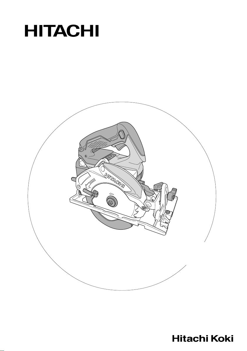
28. Support large panels to minimize the risk of blade
pinching and KICKBACK. Large panels tend to sag
under their own weight (Fig. 2). Supports must
be placed under the panel on both sides, near the
line of cut and near the edge of the panel as
shown in Fig. 1.
To minimize the risk of blade pinching and kickback.
When cutting operation requires the resting of the
saw on the work piece, the saw shall be rested
on the larger portion and the smaller piece cut
off.
To avoid kickback, do support
board or panel near the cut.
Fig. 1
Page 5
Don’t support board or panel away
from the cut.
Fig. 2
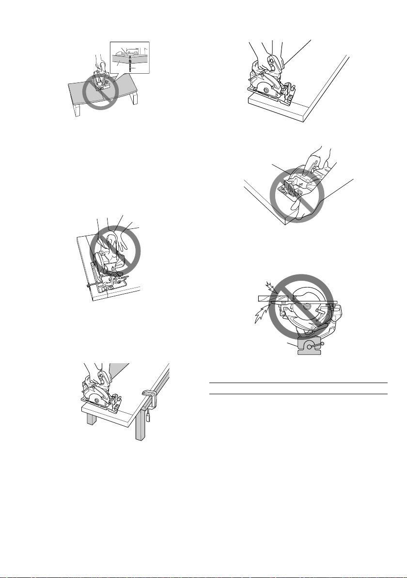
29. Use extra caution when making a “Pocket Cut”
into existing walls or other blind areas. The
protruding blade may cut objects that can cause
KICKBACK.
NEVER place your hand or fingers behind the saw
(Fig. 3). If kickback occurs, the saw could easily
jump backwards over your hand, possibly causing
severe injury.
Fig. 3
30. WARNING: It is important to support the work
piece properly and to hold the saw firmly to
prevent loss of control which could cause personal
injury. Fig. 4 illustrates typical hand support of the
saw.
A TYPICAL
ILLUSTRATION
OF PROPER
HAND
SUPPORT
Fig. 4
31. Place the wider portion of the saw base on that
part of the work piece which is solidly supported,
not on the section that will fall off when the cut
is made. As examples, Fig. 5 illustrates the RIGHT
way to cut off the end of board, and Fig. 6 the
WRONG way. If the work piece is short or small,
clamp is down.
DON’T TRY TO HOLD SHORT PLACES BY HAND!
Fig. 5
Fig. 6
32. Never attempt to saw with the circular saw held
upside down in a vise. This is extremely dangerous
and can lead to serious accidents (Fig. 7).
Vise
Fig. 7
CAUTION ON LITHIUM-ION BATTERY
To extend the lifetime, the lithium-ion battery equips
with the protection function to stop the output.
In the cases of 1 to 3 described below, when using
this product, even if you are pulling the switch, the
motor may stop. This is not the trouble but the result
of protection function.
1. When the battery power remaining runs out, the
motor stops.
In such case, charge it up immediately.
2. If the tool is overloaded, the motor may stop. In
this case, release the switch of tool and eliminate
causes of overloading. After that, you can use it
again.
3. If the battery is overheated under overload work,
the battery power may stop.
In this case, stop using the battery and let the
battery cool. After that, you can use it again.
Furthermore, please heed the following warning and
caution.
WARNING
In order to prevent any battery leakage, heat generation,
smoke emission, explosion and ignition beforehand,
please be sure to heed the following precautions.
4
Page 6

1. Make sure that swarf and dust do not collect on
the battery.
䡬 During work make sure that swarf and dust do
not fall on the battery.
䡬 Make sure that any swarf and dust falling on the
power tool during work do not collect on the
battery.
䡬 Do not store an unused battery in a location
exposed to swarf and dust.
䡬 Before storing a battery, remove any swarf and
dust that may adhere to it and do not store it
together with metal parts (screws, nails, etc.).
2. Do not pierce battery with a sharp object such
as a nail, strike with a hammer, step on, throw
or subject the battery to severe physical shock.
3. Do not use an apparently damaged or deformed
battery.
4. Do not use the battery in reverse polarity.
5. Do not connect directly to an electrical outlets or
car cigarette lighter sockets.
6. Do not use the battery for a purpose other than
those specified.
7. If the battery charging fails to complete even
when a specified recharging time has elapsed,
immediately stop further recharging.
8. Do not put or subject the battery to high
temperatures or high pressure such as into a
microwave oven, dryer, or high pressure container.
9. Keep away from fire immediately when leakage
or foul odor are detected.
10. Do not use in a location where strong static
electricity generates.
11. If there is battery leakage, foul odor, heat
generated, discolored or deformed, or in any way
appears abnormal during use, recharging or
storage, immediately remove it from the equipment
or battery charger, and stop use.
CAUTION
1. If liquid leaking from the battery gets into your
eyes, do not rub your eyes and wash them well
with fresh clean water such as tap water and
contact a doctor immediately.
If left untreated, the liquid may cause eye-problems.
2. If liquid leaks onto your skin or clothes, wash well
with clean water such as tap water immediately.
There is a possibility that this can cause skin irritation.
3. If you find rust, foul odor, overheating, discolor,
deformation, and/or other irregularities when using
the battery for the first time, do not use and return
it to your supplier or vendor.
WARNING
If an electrically conductive foreign object enters the
terminals of the lithium ion battery, a short-circuit may
occur resulting in the risk of fire. Please observe the
following matters when storing the battery.
䡬 Do not place electrically conductive cuttings, nails,
steel wire, copper wire or other wire in the storage
case.
䡬 Either install the battery in the power tool or
store by securely pressing into the battery cover
until the ventilation holes are concealed to prevent
short-circuits (See Fig. 9).
SPECIFICATIONS
Power Tool
Model C18DBL
No-load speed (Silent mode) 5000 (3000) /min
Capacity Cutting depth
Rechargeable battery BSL1850: Li-ion 18 V (5.0 Ah, 10 cells)
Weight 2.5 kg
90° 47 mm
45° 30 mm
Charger
Model UC18YFSL
Charging voltage 14.4 V – 18 V
Weight 0.5 kg
Electronic control
䡬 Soft-start
䡬 Overload protection
This protection feature cuts off the power to the
motor in the event of overloading of motor or a
conspicuous reduction in rotational speed during
operation.
When the overload protection feature has been
activated, the motor may stop.
In this case, release the tool switch and eliminate
causes of overloading.
After that you can use it again.
䡬 Overheat protection
This protection feature cuts off the power to the
motor and stops the power tool in the event of
overheating of motor during operation.
5
When the overheat protection feature has been
activated, the motor may stop.
In this case, release the tool switch and cool it down
in a few minutes.
After that you can use it again.
䡬 Rotation speed changeover function (Power mode /
Silent mode)
(Power mode / Silent mode switch function)
Each press of the Mode Selector Switch changes the
operating mode.
Silent mode reduces maximum motor RPM enabling
efficient work with less noise.
The Silent Mode Indicator Lamp lights in Silent mode.
When the load increases during Silent mode, the tool
will automatically switch to Power mode and revert
back to Silent mode when the load decreases.
In Power mode, no change is made to Silent mode
even when the load decreases.
NOTE
䡬 To enable mode changes, pull the switch once after
installing the battery.
䡬 Do not give a strong shock to the switch panel or
break it. It may lead to a trouble.
Page 7

STANDARD ACCESSORIES
1
2
3
C18DBL
(2LJRK)
C18DBL
(NN)
Standard accessories are subject to change without notice.
OPTIONAL ACCESSORIES (sold separately)
1. Battery (BSL1830, BSL1840, BSL1850)
2. Saw Blade
Use......Cutting various types of wood.
External Diam Hole Diam. No. of Teeth
125 mm 20 mm 24 pieces
3. Dust Collection Adaptor
The Dust Collection Adaptor collects sawdust when
the vacuum cleaner is attached to the power tool.
(How to attach the Dust Collection Adaptor)
Attach the Dust Collection Adaptor to the power
tool with the M4 screw (Fig. 8).
Connect the vacuum cleaner to the Dust Collection
Adaptor.
Dust collection
adapter
1 Saw Blade (mounted on tool) ................................................................................ 1
2 Hex. bar wrench 4 mm............................................................................................ 1
3 Hex. bar wrench 2.5 mm......................................................................................... 1
4 Charger (UC18YFSL) .................................................................................................. 1
5 Battery (BSL1850) ....................................................................................................... 2
6 Battery cover............................................................................................................... 1
7 Plastic case.................................................................................................................. 1
1
1 Saw Blade (mounted on tool) ................................................................................ 1
2 Hex. bar wrench 4 mm............................................................................................ 1
3 Hex. bar wrench 2.5 mm......................................................................................... 1
2
3
4
5
6
APPLICATION
Cutting various types of wood.
BATTERY REMOVAL/INSTALLATION
1. Battery removal
Hold the handle tightly and push the battery latches
to remove the battery (see Fig. 9, 10).
CAUTION
Never short-circuit the battery.
2. Battery installation
Insert the battery while observing its polarities (see
Fig. 10).
Ventilation holes
Latch
Battery
Latch
Battery
Terminals
Battery cover
Fig. 9
Handle
7
Screw
Fig. 8
Optional accessories are subject to charge without notice.
Pull out
Insert
Fig. 10
Push
6
Page 8

CHARGING
Before using the power tool, charge the battery as follows.
1. Connect the charger’s power cord to a receptacle.
When the power cord is connected, the charger’s
pilot lamp will blink in red. (At 1-second intervals)
CAUTION
Do not use the electrical cord if damaged. Have
it repaired immediately.
2. Insert the battery into the charger.
Firmly insert the battery into the charger, as shown
in Fig. 11.
Table 1
Pilot lamp
Before
charging
Battery
Fig. 11
Blinks
Charger
Indications of the pilot lamp
Lights for 0.5 seconds. Does not light for 0.5
seconds. (off for 0.5 seconds)
3. Charging
When inserting a battery in the charger, charging
will commence and the pilot lamp will light
continuously in red.
When the battery becomes fully recharged, the pilot
lamp will blink in red. (At 1-second intervals) (See
Table 1)
(1) Pilot lamp indication
The indications of the pilot lamp will be as shown
in Table 1, according to the condition of the charger
or the rechargeable battery.
While
charging
Pilot lamp
(red)
(2) Regarding the temperatures of the rechargeable
battery
The temperatures for rechargeable batteries are as
shown in Table 2, and batteries that have become
hot should be cooled for a while before being
recharged.
Table 2 Recharging ranges of batteries
Rechargeable batteries
BSL1820, BSL1830, BSL1840,
BSL1850
7
Charging
complete
Overheat
standby
Charging
impossible
Lights
Blinks
Blinks
Flickers
Lights continuously
Lights for 0.5 seconds. Does not light for 0.5
seconds. (off for 0.5 seconds)
Lights for 1 second. Does not light for 0.5
seconds. (off for 0.5 seconds)
Lights for 0.1 seconds. Does not light for 0.1
seconds. (off for 0.1 seconds)
Temperatures at
which the battery
can be recharged
0°C – 40°C
Battery overheated.
Unable to charge.
(Charging will commence
when battery cools)
Malfunction in the
battery or the charger
(3) Regarding recharging time
Depending on the combination of the charger and
batteries, the charging time will become as shown
in Table 3.
Table 3 Charging time (At 20°C)
Battery
Charger
BSL1820 Approx. 30 min.
BSL1830 Approx. 45 min.
BSL1840 Approx. 60 min.
BSL1850 Approx. 75 min.
UC18YFSL
Page 9

NOTE
The charging time may vary according to
temperature and power source voltage.
CAUTION
When the battery charger has been continuously
used, the battery charger will be heated, thus
constituting the cause of the failures. Once the
charging has been completed, give 15 minutes rest
until the next charging.
4. Disconnect the charger’s power cord from the
receptacle.
5. Hold the charger firmly and pull out the battery.
NOTE
After operation, pull out batteries from the charger
first, and then keep the batteries properly.
How to make the batteries perform longer
(1) Recharge the batteries before they become
completely exhausted.
When you feel that the power of the tool becomes
weaker, stop using the tool and recharge its battery.
If you continue to use the tool and exhaust the
electric current, the battery may be damaged and
its life will become shorter.
(2) Avoid recharging at high temperatures.
A rechargeable battery will be hot immediately after
use. If such a battery is recharged immediately after
use, its internal chemical substance will deteriorate,
and the battery life will be shortened. Leave the
battery and recharge it after it has cooled for a
while.
CAUTION
䡬 If the battery is charged while it is heated because
it has been left for a long time in a location subject
to direct sunlight or because the battery has just
been used, the pilot lamp of the charger lights for
1 second, does not light for 0.5 seconds (off for
0.5 seconds). In such a case, first let the battery
cool, then start charging.
䡬 When the pilot lamp flickers in red (at 0.2-seconds
intervals), check for and take out any foreign objects
in the charger’s battery connector. If there are no
foreign objects, it is probable that the battery or
charger is malfunctioning. Take it to your authorized
Service Center.
䡬 Since the built-in micro computer takes about 3
seconds to confirm that the battery being charged
with UC18YFSL is taken out, wait for a minimum
of 3 seconds before reinserting it to continue
charging. If the battery is reinserted within 3 seconds,
the battery may not be properly charged.
䡬 If the pilot lamp does not blink in red (every second)
even though the charger cord is connected to the
power, it indicates that the protection circuit of the
charger may be activated.
Remove the cord from the power and then connect
it again after 30 seconds or so. If this does not
cause the pilot lamp to blink in red (every second),
please take the charger to the Hitachi Authorized
Service Center.
PRIOR TO OPERATION
1. Setting up and checking the work environment
Check if the work environment is suitable by
following the precautions.
2. Prepare a wooden workbench (Fig. 12)
Since the saw blade will extend beyond the lower
surface of the lumber, place the lumber on a
workbench when cutting. If a square block is utilized
as a workbench, select level ground to ensure it
is properly stabilized. An unstable workbench will
result in hazardous operation.
CAUTION
To avoid possible accident, always ensure that the
portion of lumber remaining after cutting is securely
anchored or held in position.
Lumber
Workbench
Fig. 12
Base
Saw blade
ADJUSTING THE SAW PRIOR TO USE
CAUTION
Pull out battery before doing any adjusting.
1. Adjusting the cutting depth
As shown in Fig. 13, hold the handle with one hand
while loosening the lever with the other.
The cutting depth can be adjusted by moving the
base to the desired position. In such manner adjust
the cutting depth and then securely retighten the
lever.
2. Adjusting the angle of inclination
As shown in Fig. 14 by loosening the clamp lever
on the incline gauge, the saw blade may be inclined
to a maximum angle of 45° in relation to the base.
After having completed the adjustment, reconfirm
that the clamp lever are firmly tightened.
Handle
Lever
Base
Fig. 13
8
Page 10

Clamp lever
Base
Fig. 14
Front Scale at 45˚ incline
Premarked line
Front scale
when not
inclined
Saw blade
Fig. 15
NOTE
Values of the inclined gauge provided on the base
merely serve as a rough guideline. For cutting
operation at an inclined posture, use the circular
saw after adjusting the angle between the base and
the saw blade with a protractor, etc.
3. Regulating the guide (Fig. 16)
The cutting position can be regulated by moving
the guide to the left or right after loosening its knob
bolt. The guide may be mounted on either the right
or left side of the tool.
Knob bolt
U-Nut M5
Mounting screw
(2) Retract the lower guard into the saw cover.
(3) Insert wood chip in the rear side of the saw
blade base, and mark the position on the base
(Fig. 18).
Lower guard
(4) Move the marked wood chip to the front of the
base, and turn the parallelism adjustment screw
so that the marking corresponds to the base side
(Fig. 19).
Saw cover hinge
Fig. 17
Wood chip
Saw cover
Fig. 18
Wood chip
Guide
Fig. 16
4. Fine tuning of parallelism
It is possible to fine-tune the parallelism of the saw
blade to the base using the parallelism adjustment
screw.
Adjustment has already been made at the time of
shipment from the factory. However, in the unlikely
event of parallelism being faulty, adjust as follows.
(1) Unfasten only the mounting screws of the saw
cover hinge portion (Fig. 17).
9
Parallelism
adjustment screw
Fig. 19
NOTE
After parallelism adjustment, if the saw cover hinge
portion is loose, tighten the M5 U-Nut. Do not over
tighten the nut as this may result in deformation
of the bevel plate.
(5) After adjustment, fasten the mounting screws
tightly in place.
NOTE
Parallelism may be slightly faulty if the cutting
depth is adjusted after parallelism adjustment.
5. Adjusting the guide piece
On the circular saw, it is possible to make fine
adjustment of the fixing position of the guide piece,
where the saw blade and the premarked line are
to be aligned.
When the saw is shipped from the factory, the
linear portion of a front scale on the guide piece
is aligned with the central position of the saw blade
(Fig. 20).
Page 11

Loosen the fixed M4 screw on the guide piece,
should the fixing position be wrong, and make
necessary adjustment of the position.
M4 screw
Front scale
at 45˚ incline
Premarked line
Fig. 20
Premarked line
Front scale when
not inclined
Guide piece
Saw blade
HOW TO USE
1. Operation of switch (Fig. 21)
(switch trigger and light switch)
(1) For safe operation of the machine, a “switch lock”
is provided on the side of a handle.
If the “switch trigger” is pulled in a state where
“switch lock” is pressed in the direction of the
arrow mark, the main switch can be turned ON.
And the “switch lock” is used as the “light switch”.
If the “switch lock (light switch)” is pressed in a
state, the light is turned ON.
(2) After the switch is turned ON, even when you
release your hand from the switch lock, the body
continues running and the light continues being
turned ON as long as you keep on pulling the
switch trigger.
(3) If you release the switch trigger, you can turn OFF
the switch and the “switch lock” returns to the
original position automatically and the light turns
OFF too.
Switch lock
Switch trigger
Fig. 21
CAUTION
䡬 Do not fix and secure the switch lock. Besides, keep
your finger off the switch trigger when the circular
saw is being carried around. Otherwise, the main
body switch can be inadvertently turned ON,
resulting in unexpected accidents.
䡬 Keep the light ON during cutting operation only.
If it is lit ON in other cases, the main body switch
can be inadvertently turned ON, resulting in
unexpected accidents.
䡬 If the main body is left as it is with the battery
inserted, there can be a case where the [switch lock]
touches the floor and/or wall surface and lights up
continuously, depending on the direction of the
body. Be careful, since continuous lighting can easily
make a full-charged battery go dead in about 3
hours.
2. About Remaining Battery Indicator
When pressing the remaining battery indicator
switch, the remaining battery indicator lamp lights
and the battery remaining power can be checked.
(Fig. 22) When releasing your finger from the
remaining battery indicator switch, the remaining
battery indicator lamp goes off. The Table 4 shows
the state of remaining battery indicator lamp and
the battery remaining power.
Silent Mode
Indicator Lamp
Mode Selector
Switch
State of lamp Battery Remaining Power
As the remaining battery indicator shows somewhat
differently depending on ambient temperature and
battery characteristics, read it as a reference.
NOTE
䡬 Do not give a strong shock to the switch panel or
break it. It may lead to a trouble.
䡬 To save the battery power consumption, the
remaining battery indicator lamp lights while
pressing the remaining battery indicator switch.
3. Cutting procedures
CAUTION
䡬 Recheck that the saw blade is securely clamped.
䡬 Confirm that the wing nut for adjusting the slot
depth, the wing bolt for adjusting the angle of
inclination are securely clamped.
(1) Place the base on the material, then align the
premarked line and the sawblade with the notch
at the front of the base (Fig. 15).
When the base is not slanted, use the large cutout
as the guide (Fig. 15, Fig. 23).
Remaining battery
indicator switch
Fig. 22
Table 4
The battery remaining power
is enough.
The battery remaining power
is a half.
The battery remaining power
is nearly empty.
Re-charge the battery soonest
possible.
Remaining
battery
indicator
lamp
10
Page 12

If the base is slanted (45 degrees), use the small
front scale as the guide (Fig. 15, Fig. 24).
MOUNTING AND DISMOUNTING THE SAW
BLADE
CAUTION
To avoid serious accident, ensure the switch is in
the OFF position, and pull out the battery.
1. Dismounting the saw blade
(1) Set the cutting volume at maximum, and place the
Circular Saw as shown in Fig. 25.
Hex. bolt
Washer (B)
Hex. bar wrench
Premarked line
Front scale when not inclined
Fig. 23
Front scale at
45˚ incline
(2) Ensure that the switch is turned to the ON position
before the saw blade comes in contact with the
lumber. The switch is turned ON when the trigger
is squeezed; and OFF when the trigger is released.
Moving the saw straight at a constant speed will
produce optimum cutting.
CAUTION
䡬 Before starting to saw, ensure that the saw blade
has reached full speed revolution.
䡬 Should the saw blade be stopped or made an
abnormal noise during operation, turn off the switch
immediately.
䡬 When finished with a job, pull out the battery from
the main body.
䡬 Twisting and forcibly pressing the saw during cutting
can result in unreasonable pressure on the motor,
so try to go straight quietly.
䡬 In the situation where the circular saw is continuously
operated while replacing the battery with stocked
spare batteries one after another, the motor tends
to overheat. Therefore, whenever the housing
becomes hot, give the saw a break for a while.
䡬 Avoid cutting operation in a state where the base
bottom is afloat from the material being cut.
Otherwise, the motor can get locked.
11
Premarked line
Fig. 24
Lock lever
Fig. 25
(2) Depress the lock lever, lock the spindle, and remove
the Hex. bolt and washer (B) with the hex. bar
wrench.
(3) While holding the lower guard lever to keep the
lower guard fully retracted into the saw cover,
remove the saw blade (Fig. 26).
Lower guard lever
Saw cover
Saw blade
Fig. 26
2. Mounting the Saw Blade
CAUTION
If the hex. bolt is worked using other tools than
the provided hex. bar wrench, excessive tightening
and insufficient tightening may take place resulting
in injury.
(1) Thoroughly remove any sawdust which has
accumulated on the spindle, bolt and washers.
(2) As shown in Fig. 27, the side of Washer (A) with
a projected center the same diameter as the inner
diameter of the saw blade and the concave side
of Washer (B) must be fitted to the saw blade sides.
(3) To assure proper rotation direction of the saw blade,
the arrow direction on the saw blade must coincide
with the arrow direction on the saw cover.
(4) Using the fingers, tighten the hex. bolt retaining the
saw blade as much as possible. Then depress the
lock lever, lock the spindle, and thoroughly tighten
the hex. bolt.
CAUTION
After having attached the saw blade, reconfirm that
the lock lever is firmly secured in the prescribed
position.
Page 13

Hex. bolt
Washer (B)
Fig. 27
Washer (A)
Spindle
Saw blade
MAINTENANCE AND INSPECTION
CAUTION
Pull out battery before doing any inspection or
maintenance.
1. Inspecting the saw blade
Since use of a dull saw blade will degrade efficiency
and cause possible motor malfunction, sharpen or
replace the saw blade as soon as abrasion is noted.
CAUTION
If a dull saw blade is used, reactive force is increased
during cutting operation. Avoid the use of the dull
saw blade without repair.
2. Inspecting the mounting screws
Regularly inspect all mounting screws and ensure
that they are properly tightened. Should any of the
screws be loose, retighten them immediately. Failure
to do so could result in serious hazard.
3. Maintenance of the motor
The motor unit winding is the very “heart” of the
power tool.
Exercise due care to ensure the winding does not
become damaged and/or wet with oil or water.
4. Performance checkup and maintenance of lower
guard
Keep the lower guard in good shape for smooth
performance at all times. Be sure to make prompt
repair in case of any malfunction.
For safe and proper working, always keep the machine
and ventilation slots clean. The lower guard must
always be able to more freely and retract
automatically. Therefore, always keep the area around
the lower guard clean. Remove dust and chips by
blowing out with compressed air or with a brush.
5. Adjusting the base and saw blade to maintain
perpendicularity
The angle between the base and the saw blade has
been adjusted to 90°, however should this
perpendicularity be lost for some reason, adjust in
the following manner:
(1) Turn the base face up (Fig. 28) and loosen the
clamp lever.
(2) Apply a square to the base and the saw blade and
turning the slotted set screw with a slotted-head
screwdriver, shift the position of the base to produce
the desired right angle.
Square
Base
6. Check for dust
Dust may be removed with a clean rag or a cloth
dampened with soapy water.
Do not use bleach, chlorine, gasoline or thinner, for
they may damage the plastics.
7. Storage
Storing in a place below 40°C and out of the reach
of children.
NOTE
Make sure that the battery is fully charged when
stored for a long period (3 months or more). The
battery with smaller capacity may not be able to
be charged when used, if stored for a long period.
NOTE
Storing lithium-ion batteries
Make sure the lithium-ion batteries have been fully
charged before storing them.
Prolonged storage of batteries with a low charge
may result in performance deterioration, significantly
reducing battery usage time or rendering the
batteries incapable of holding a charge.
However, significantly reduced battery usage time
may be recovered by repeatedly charging and using
the batteries two to five times.
If the battery usage time is extremely short despite
repeated charging and use, consider the batteries
dead and purchase new batteries.
8. Service and repairs
All quality power tools will eventually require
servicing or replacement of parts because of wear
from normal use. To assure that only genuine
replacement parts must be used, all service and
repairs must be performed by a HITACHI
AUTHORIZED SERVICE CENTER, ONLY.
9. Service parts list
CAUTION
Repair, modification and inspection of Hitachi Power
Tools must be carried out by a Hitachi Authorized
Service Center.
This Parts List will be helpful if presented with the
tool to the Hitachi Authorized Service Center when
requesting repair or other maintenance.
In the operation and maintenance of power tools,
the safety regulations and standards prescribed in
each country must be observed.
MODIFICATION
Hitachi Power Tools are constantly being improved
and modified to incorporate the latest technological
advancements.
Accordingly, some parts may be changed without
prior notice.
Saw blade
Slotted set screw
Clamp lever
Fig. 28
12
Page 14

Important notice on the batteries for the Hitachi
cordless power tools
Please always use one of our designated genuine
batteries. We cannot guarantee the safety and
performance of our cordless power tool when
used with batteries other than these designated
by us, or when the battery is disassembled and
modified (such as disassembly and replacement
of cells or other internal parts).
NOTE
Due to HITACHI’s continuing program of research and
development, the specifications herein are subject to
change without prior notice.
13
Page 15

A
C
B
A
B
C
501
502
503
504
505
1
2
3
4
5
6
7
8
9
11
12
13
14
15
16
17
18
19
20
21
22
23
24
25
29
30
31
32
33
34
37
30
38
39
35
40
41
42
36
43
44
43
26
27
28
45
46
47
48
49
52
50
55
56
57
58
54
53
60
61
62
59
65
63
66
67
68
59
69
70
71
72
73
64
59
74
10
53
64
66
71
75
51
Q’TY
Part Name
42 SWITCH 1
No.
Item
Q’TY
Part Name
1 WASHER (A) 1
No.
Item
5
MACHINE SCREW
(W/WASHERS) M4×14
43
44 HANDLE SET 1
45 FLOW GUIDE (C) 1
46 HOUSING SET 1
47 CUSION 2
2 RETAINING RING FOR D10 SHAFT 1
3 FIRST GEAR 1
4 O-RING (S-14) 1
5 WOODRUFF KEY 1
6 SECOND SHAFT ASS'Y (INCLUD.2-5) 1
2
(W/WASHERS) M4×35
MACHINE SCREW
48 RUBBER BUSHING 1
49 TAPPING SCREW (W/FLANGE) D3×20 4
51 NAME PLATE 1
52 TAPPING SCREW (W/FLANGE) D4×16 3
50
3
1
(INCLUD.6-9, 16-18)
BEARING HOLDER ASS'Y
MACHINE SCREW
7 MACHINE SCREW M3×83
8 BALL BEARING 606VVC2 1
9 BEARING HOLDER 1
10
11
RETAINING RING (E-TYPE)
(W/WASHERS) M4×81
MACHINE SCREW
54 GUIDE PIECE 1
53
(W/SP. WASHER) M4×12
12 LOWER GUARD 1
13 RETURN SPRING 1
14 RETAINING RING FOR D22 SHAFT 1
1
FOR D8 SHAFT
55
56 SPECIAL NUT M6 1
57 WASHER M6 1
58 CLAMP LEVER 1
15 WASHER (A) 1
16 SPINDLE GEAR ASS'Y 1
17 BEARING COVER 1
18 BALL BEARING 6900VVCMPS2L 1
1
(SEAL LOCK) M6×8
SLOTTED HD. SET SCREW
59 U-NUT M5 3
60 WING BOLT M6×18 1
61 SPRING 1
62 BASE (A) 1
63 BOLT (SQUARE) M6 1
64 SPECIAL BOLT 1
65 ADJUSTING SCREW (A) 1
66
67 TAPPING SCREW D3×12 1
68 CONTROLLER COVER 1
69 WAVE WASHER 8 1
3
1
STATOR FET PCB ASS'Y
MACHINE SCREW
(W/WASHERS) M4×12
(INCLUD.41, 42)
19 KNOB 1
20 TAPPING SCREW D4×10 1
21 125MM SAW BLADE 1
22 WASHER (B) 1
23 HEX. BOLT (W/FLANGE) M5×14 1
24 SAW COVER 1
26
25
27 ROTOR 1
28 RUBBER RING (A) 1
29 MACHINE SCREW M4×61
1
(W/SP. WASHER) M4×8
MACHINE SCREW
70 COVER PLATE 1
71 LINK 1
72 LEVER 1
73
74 BATTERY BSL1850 (INCLUD.505) 2
75 BASE ASS'Y (INCLUD.53-64, 66, 71) 1
501 CHARGER (MODEL UC18YFSL) 1
502 HEX.BAR WRENCH 2.5MM 1
2
SEAL LOCK HEX. SOCKET SET
SCREW M5×6
30
31 GEAR COVER 1
32 SPRING HOOK 1
33 SPRING 1
34 LOCK LEVER 1
35 SPRING 1
36 KNOB 1
37 CAM 1
503 HEX.BAR WRENCH 4MM 1
504 CASE 1
38 LOCK SLEEVE 1
39 CAM SHAFT 1
505 BATTERY COVER 1
2
MACHINE SCREW
(W/WASHER) M3.5×6
40 TRIGGER 1
41
14
Page 16

Hitachi Koki Co., Lt
d.
Shinagawa Intercity Tower A, 15-1, Konan 2-chome,
Minato-ku, Tokyo, Japan
Code No. C99212912 G
403
Printed in China
 Loading...