

Page 1
Designed for operating in USA & Canada only.
When this product is used in areas other than the USA & Canada,
we cannot guarantee the product quality and performance.
Model
Modèle
Modelo
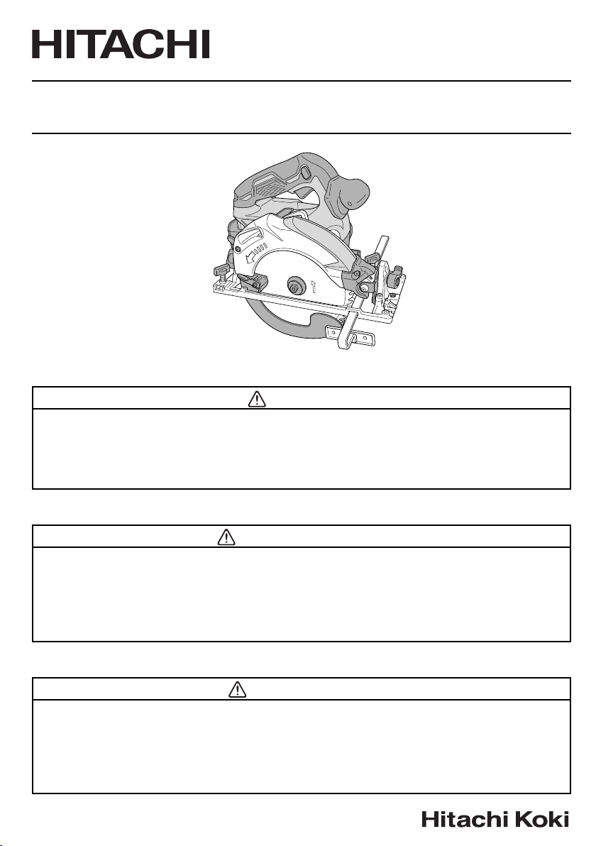
C 18DBAL
Cordless Circular Saw
Scie circulaire sans fi l
Sierra circular a batería
SAFETY INSTRUCTIONS AND INSTRUCTION MANUAL
WARNING
IMPROPER OR UNSAFE use of this power tool can result in death or serious bodily injury!
This manual contains important information about product safety. Please read and
understand this manual BEFORE operating the power tool. Please keep this manual
available for other users and owners before they use the power tool. This manual should be
stored in safe place.
INSTRUCTIONS DE SECURITE ET MODE D’EMPLOI
AVERTISSEMENT
Une utilisation INCORRECTE OU DANGEREUSE de cet outil motorisé peut entraîner la
mort ou de sérieuses blessures corporelles!
Ce mode d’emploi contient d’importantes informations à propos de la sécurité de ce produit.
Prière de lire et de comprendre ce mode d’emploi AVANT d’utiliser l’outil motorisé. Garder ce
mode d’emploi à la disponibilité des autres utilisateurs et propriétaires avant qu’ils utilisent
l’outil motorisé. Ce mode d’emploi doit être conservé dans un endroit sûr.
INSTRUCCIONES DE SEGURIDAD Y MANUAL DE INSTRUCCIONES
ADVERTENCIA
¡La utilización INAPROPIADA O PELIGROSA de esta herramienta eléctrica puede resultar
en lesiones de gravedad o la muerte!
Este manual contiene información importante sobre la seguridad del producto. Lea y
comprenda este manual ANTES de utilizar la herramienta eléctrica. Guarde este manual
para que puedan leerlo otras personas antes de utilizar la herramienta eléctrica. Este
manual debe ser guardado en un lugar seguro.
Page 2

English
CONTENTS
Page Page
IMPORTANT SAFETY INFORMATION ..................... 3
MEANINGS OF SIGNAL WORDS ............................. 3
SAFETY........................................................................ 3
GENERAL POWER TOOL SAFETY WARNINGS ..... 3
CIRCULAR SAW SAFETY WARNINGS .................... 5
SPECIFIC SAFETY RULES ....................................... 6
IMPORTANT SAFETY INSTRUCTIONS FOR
BATTERY CHARGER ........................................ 6
IMPORTANT SAFETY INSTRUCTIONS FOR USE
OF THE BATTERY AND BATTERY CHARGER
CAUTION ON LITHIUM-ION BATTERY .................... 8
REGARDING LITHIUM-ION BATTERY
TRANSPORTATION .......................................... 9
USB DEVICE CONNECTION PRECAUTIONS ......... 9
FUNCTIONAL DESCRIPTION .................................. 10
NAME OF PARTS .................................................... 10
... 7
SPECIFICATIONS ................................................... 11
ASSEMBLY AND OPERATION ................................. 13
APPLICATIONS ....................................................... 13
REMOVAL AND INSTALLATION METHOD OF
BATTERY ......................................................... 13
CHARGING METHOD ............................................. 13
PRIOR TO OPERATION .......................................... 15
ADJUSTING THE SAW PRIOR TO USE ................. 16
OPERATION ............................................................ 18
MAINTENANCE AND INSPECTION ......................... 23
ACCESSORIES ......................................................... 25
STANDARD ACCESSORIES .................................. 25
OPTIONAL ACCESSORIES .................................... 25
PART LIST ................................................................. 76
Français
TABLE DES MATIÈRES
Page Page
INFORMATIONS IMPORTANTES DE SÉCURITÉ ... 26
SIGNIFICATION DES MOTS D’AVERTISSEMENT... 26
SECURITE ................................................................. 26
AVERTISSEMENTS DE SÉCURITÉ GÉNÉRAUX
CONCERNANT LES OUTILS ÉLECTRIQUES... 26
AVERTISSEMENTS DE SÉCURITÉ RELATIFS
À LA SCIE CIRCULAIRE .................................. 28
REGLES DE SECURITE SPECIFIQUES ................. 29
CONSIGNES DE SÉCURITÉ IMPORTANTES
POUR LE CHARGEUR DE BATTERIE ............ 30
CONSIGNES DE SÉCURITÉ IMPORTANTES POUR
L’UTILISATION DE LA BATTERIE ET DU
CHARGEUR DE BATTERIE ............................. 31
PRÉCAUTIONS RELATIVES A LA BATTERIE
AU LITHIUM ION .............................................. 32
À PROPOS DU TRANSPORT DE LA BATTERIE
LITHIUM-ION ................................................... 33
PRÉCAUTIONS LORS DE LA CONNEXION DU
DISPOSITIF USB ............................................. 33
Español
Página Página
INFORMACIÓN IMPORTANTE SOBRE
SEGURIDAD ................................................... 51
SIGNIFICADO DE LAS PALABRAS DE
SEÑALIZACIÓN .............................................. 51
SEGURIDAD .............................................................. 51
ADVERTENCIAS DE SEGURIDAD GENERAL
DE LA HERRAMIENTA ELÉCTRICA .............. 51
ADVERTENCIAS DE SEGURIDAD DE LA
SIERRA CIRCULAR ......................................... 53
NORMAS ESPECÍFICOS DE SEGURIDAD ............ 54
INSTRUCCIONES IMPORTANTES DE
SEGURIDAD PARA EL CARGADOR DE
BATERÍAS ........................................................ 55
INSTRUCCIONES IMPORTANTES DE SEGURIDAD
PARA LA BATERÍA Y EL CARGADOR DE
BATERÍAS ........................................................ 56
ADVERTENCIA DE LA BATERÍA DE LITIO............. 57
A PROPÓSITO DEL TRANSPORTE DE LA
BATERÍA DE IONES DE LITIO ......................... 58
PRECAUCIONES DE CONEXIÓN DEL
DISPOSITIVO USB .......................................... 58
DESCRIPTION FONCTIONNELLE ........................... 34
ASSEMBLAGE ET FONCTIONNEMENT .................. 37
ENTRETIEN ET INSPECTION .................................. 48
ACCESSOIRES ......................................................... 50
LISTA DES PIÈCES ................................................... 76
ÍNDICE
DESCRIPCIÓN FUNCIONAL .................................... 59
MONTAJE Y OPERACIÓN ........................................ 62
MANTENIMIENTO E INSPECCIÓN .......................... 73
ACCESSORIOS ......................................................... 75
LISTA DE PIEZAS ..................................................... 76
NOM DES PARTIES ................................................ 34
SPECIFICATIONS ................................................... 35
UTILISATIONS ........................................................ 37
MÉTHODE DE RETRAIT ET D’INSTALLATION
DE LA BATTERIE ............................................. 37
MÉTHODE DE RECHARGE .................................... 37
AVANT L’UTILISATION ........................................... 39
RÉGLAGE DE LA SCIE AVANT UTILISATION........ 41
UTILISATION ........................................................... 43
ACCESSOIRES STANDARD .................................. 50
ACCESSOIRES EN OPTION................................... 50
NOMENCLATURA .................................................. 59
ESPECIFICACIONES .............................................. 60
APLICACIONES ...................................................... 62
MÉTODO DE EXTRACCIÓN E INSTALACIÓN DE
LA BATERÍA ..................................................... 62
MÉTODO DE CARGA ............................................. 62
ANTES DE LA OPERACIÓN ................................... 64
AJUSTE DE LA SIERRA ANTES DEL USO ............ 66
OPERACIÓN ........................................................... 68
ACCESORIOS ESTÁNDAR .................................... 75
ACCESORIOS OPCIONALES ................................. 75
Page 3

English
IMPORTANT SAFETY INFORMATION
Read and understand all of the safety precautions, warnings and operating instructions in the Instruction Manual before
operating or maintaining this power tool.
Most accidents that result from power tool operation and maintenance are caused by the failure to observe basic safety
rules or precautions. An accident can often be avoided by recognizing a potentially hazardous situation before it occurs,
and by observing appropriate safety procedures.
Basic safety precautions are outlined in the “SAFETY” section of this Instruction Manual and in the sections which
contain the operation and maintenance instructions.
Hazards that must be avoided to prevent bodily injury or machine damage are identifi ed by WARNINGS on the power
tool and in this Instruction Manual.
NEVER use this power tool in a manner that has not been specifi cally recommended by HITACHI.
MEANINGS OF SIGNAL WORDS
WARNING indicates a potentially hazardous situations which, if ignored, could result in death or serious injury.
CAUTION indicates a potentially hazardous situations which, if not avoided, may result in minor or moderate injury, or
may cause machine damage.
NOTE emphasizes essential information.
SAFETY
GENERAL POWER TOOL SAFETY WARNINGS
WARNING
Read all safety warnings and all instructions.
Failure to follow the warnings and instructions may result in electric shock, fi re and/or serious injury.
Save all warnings and instructions for future reference.
The term “power tool” in the warnings refers to your mains- operated (corded) power tool or battery-operated
(cordless) power tool.
1) Work area safety
a) Keep work area clean and well lit.
Cluttered or dark areas invite accidents.
b) Do not operate power tools in explosive
atmospheres, such as in the presence of
fl ammable liquids, gases or dust.
Power tools create sparks which may ignite the
dust or fumes.
c) Keep children and bystanders away while
operating a power tool.
Distractions can cause you to lose control.
2) Electrical safety
a) Power tool plugs must match the outlet.
Never modify the plug in any way.
Do not use any adapter plugs with earthed
(grounded) power tools.
Unmodifi ed plugs and matching outlets will reduce
risk of electric shock.
b) Avoid body contact with earthed or grounded
surfaces such as pipes, radiators, ranges and
refrigerators.
There is an increased risk of electric shock if your
body is earthed or grounded.
c) Do not expose power tools to rain or wet
conditions.
Water entering a power tool will increase the risk
of electric shock.
d) Do not abuse the cord. Never use the cord for
carrying, pulling or unplugging the power tool.
Keep cord away from heat, oil, sharp edges or
moving parts.
Damaged or entangled cords increase the risk of
electric shock.
e) When operating a power tool outdoors, use
an extension cord suitable for outdoor use.
Use of a cord suitable for outdoor use reduces the
risk of electric shock.
f) If operating a power tool in a damp location
is unavoidable, use a residual current device
(RCD) protected supply.
Use of an RCD reduces the risk of electric shock.
3) Personal safety
a) Stay alert, watch what you are doing and use
common sense when operating a power tool.
Do not use a power tool while you are tired
or under the infl uence of drugs, alcohol or
medication.
3
Page 4

English
A moment of inattention while operating power
tools may result in serious personal injury.
b) Use personal protective equipment. Always
wear eye protection.
Protective equipment such as dust mask, non-skid
safety shoes, hard hat, or hearing protection used
for appropriate conditions will reduce personal
injuries.
c) Prevent unintentional starting. Ensure the
switch is in the off -position before connecting
to power source and/or battery pack, picking
up or carrying the tool.
Carrying power tools with your fi nger on the switch
or energising power tools that have the switch on
invites accidents.
d) Remove any adjusting key or wrench before
turning the power tool on.
A wrench or a key left attached to a rotating part of
the power tool may result in personal injury.
e) Do not overreach. Keep proper footing and
balance at all times.
This enables better control of the power tool in
unexpected situations.
f) Dress properly. Do not wear loose clothing or
jewellery. Keep your hair, clothing and gloves
away from moving parts.
Loose clothes, jewellery or long hair can be caught
in moving parts.
g) If devices are provided for the connection
of dust extraction and collection facilities,
ensure these are connected and properly
used.
Use of dust collection can reduce dust-related
hazards.
4) Power tool use and care
a) Do not force the power tool. Use the correct
power tool for your application.
The correct power tool will do the job better and
safer at the rate for which it was designed.
b) Do not use the power tool if the switch does
not turn it on and off .
Any power tool that cannot be controlled with the
switch is dangerous and must be repaired.
c) Disconnect the plug from the power source
and/or the battery pack from the power tool
before making any adjustments, changing
accessories, or storing power tools.
Such preventive safety measures reduce the risk
of starting the power tool accidentally.
d) Store idle power tools out of the reach of
children and do not allow persons unfamiliar
with the power tool or these instructions to
operate the power tool.
Power tools are dangerous in the hands of
untrained users.
e) Maintain power tools. Check for misalignment
or binding of moving parts, breakage of parts
and any other condition that may aff ect the
power tool’s operation.
If damaged, have the power tool repaired
before use.
Many accidents are caused by poorly maintained
power tools.
f) Keep cutting tools sharp and clean.
Properly maintained cutting tools with sharp
cutting edges are less likely to bind and are easier
to control.
g) Use the power tool, accessories and tool bits
etc. in accordance with these instructions,
taking into account the working conditions and
the work to be performed.
Use of the power tool for operations diff erent
from those intended could result in a hazardous
situation.
5) Battery tool use and care
a) Recharge only with the charger specifi ed by
the manufacturer.
A charger that is suitable for one type of battery
pack may create a risk of fi re when used with
another battery pack.
b) Use power tools only with specifi cally
designated battery packs.
Use of any other battery packs may create a risk of
injury and fi re.
c) When battery pack is not in use, keep it away
from other metal objects like paper clips,
coins, keys, nails, screws, or other small metal
objects, that can make a connection from one
terminal to another.
Shorting the battery terminals together may cause
burns or a fi re.
d) Under abusive conditions, liquid may be
ejected from the battery; avoid contact. If
contact accidentally occurs, fl ush with water.
If liquid contacts eyes, additionally seek
medical help.
Liquid ejected from the battery may cause irritation
or burns.
6) Service
a) Have your power tool serviced by a
qualifi ed repair person using only identical
replacement parts.
This will ensure that the safety of the power tool is
maintained.
– WARNING –
To reduce the risk of injury, user must read
instruction manual.
4
Page 5
English
WARNING:
Some dust created by power sanding, sawing,
grinding, drilling, and other construction activities
contains chemicals known to the State of California
to cause cancer, birth defects or other reproductive
harm. Some examples of these chemicals are:
●
Lead from lead-based paints,
●
Crystalline silica from bricks and cement and other
masonry products, and
●
Arsenic and chromium from chemically-treated
lumber.
Your risk from these exposures varies, depending on
how often you do this type of work. To reduce your
exposure to these chemicals: work in a well ventilated
area, and work with approved safety equipment, such
as those dust masks that are specially designed to
fi lter out microscopic particles.
CIRCULAR SAW SAFETY WARNINGS
Cutting procedures
a) DANGER: Keep hands away from cutting
area and the blade. Keep your second hand on
auxiliary handle, or motor housing.
If both hands are holding the saw, they cannot be cut
by the blade.
b) Do not reach underneath the workpiece.
The guard cannot protect you from the blade below
the workpiece.
c) Adjust the cutting depth to the thickness of the
workpiece.
Less than a full tooth of the blade teeth should be
visible below the workpiece.
d) Never hold piece being cut in your hands or
across your leg. Secure the workpiece to a stable
platform.
It is important to support the work properly to minimize
body exposure, blade binding, or loss of control.
e) Hold the power tool by insulated gripping
surfaces only, when performing an operation
where the cutting tool may contact hidden wiring.
Contact with a “live” wire will also make exposed
metal parts of the power tool “live” and could give the
operator an electric shock.
f) When ripping always use a rip fence or straight
edge guide.
This improves the accuracy of cut and reduces the
chance of blade binding.
g) Always use blades with correct size and shape
(diamond versus round) of arbour holes.
Blades that do not match the mounting hardware of
the saw will run eccentrically, causing loss of control.
h) Never use damaged or incorrect blade washers
or bolt.
The blade washers and bolt were specially designed
for your saw, for optimum performance and safety of
operation.
Kickback causes and related warnings
– kickback is a sudden reaction to a pinched, bound or
misaligned saw blade, causing an uncontrolled saw to lift
up and out of the workpiece toward the operator;
– when the blade is pinched or bound tightly by the kerf
closing down, the blade stalls and the motor reaction
drives the unit rapidly back toward the operator;
– if the blade becomes twisted or misaligned in the cut, the
teeth at the back edge of the blade can dig into the top
surface of the wood causing the blade to climb out of the
kerf and jump back toward the operator.
Kickback is the result of saw misuse and/or incorrect
operating procedures or conditions and can be avoided by
taking proper precautions as given below.
a) Maintain a fi rm grip with both hands on the saw
and position your arms to resist kickback forces.
Position your body to either side of the blade,
but not in line with the blade.
Kickback could cause the saw to jump backwards,
but kickback forces can be controlled by the operator,
if proper precautions are taken.
b) When blade is binding, or when interrupting a
cut for any reason, release the trigger and hold
the saw motionless in the material until the blade
comes to a complete stop.
Never attempt to remove the saw from the work
or pull the saw backward while the blade is in
motion or kickback may occur.
Investigate and take corrective actions to eliminate
the cause of blade binding.
c) When restarting a saw in the workpiece, centre
the saw blade in the kerf and check that saw
teeth are not engaged into the material.
If saw blade is binding, it may walk up or kickback
from the workpiece as the saw is restarted.
d) Support large panels to minimise the risk of
blade pinching and kickback.
Large panels tend to sag under their own weight.
Supports must be placed under the panel on both
sides, near the line of cut and near the edge of the
panel.
e) Do not use dull or damaged blades.
Unsharpened or improperly set blades produce
narrow kerf causing excessive friction, blade binding
and kickback.
f) Blade depth and bevel adjusting locking levers
must be tight and secure before making cut.
If blade adjustment shifts while cutting, it may cause
binding and kickback.
g) Use extra caution when sawing into existing
walls or other blind areas.
The protruding blade may cut objects that can cause
kickback.
5
Page 6

English
Lower guard function
a) Check lower guard for proper closing before each
use. Do not operate the saw if lower guard does
not move freely and close instantly. Never clamp
or tie the lower guard into the open position.
If saw is accidentally dropped, lower guard may be
bent.
Raise the lower guard with the retracting handle and
make sure it moves freely and does not touch the
blade or any other part, in all angles and depths of cut.
b) Check the operation of the lower guard spring.
If the guard and the spring are not operating
properly, they must be serviced before use.
Lower guard may operate sluggishly due to damaged
parts, gummy deposits, or a build-up of debris.
c) Lower guard should be retracted manually
only for special cuts such as “plunge cuts” and
“compound cuts”.
Raise lower guard by retracting handle and as soon
as blade enters the material, the lower guard must be
released.
For all other sawing, the lower guard should operate
automatically.
d) Always observe that the lower guard is covering
the blade before placing saw down on bench or
fl oor.
An unprotected, coasting blade will cause the saw to
walk backwards, cutting whatever is in its path.
Be aware of the time it takes for the blade to stop after
switch is released.
SPECIFIC SAFETY RULES
1. Never touch moving parts.
Never place your hands, fi ngers or other body parts
near the tool’s moving parts.
2. Never operate without all guards in place.
Never operate this tool without all guards or safety
features in place and in proper working order. If
maintenance or servicing requires the removal of a
guard or safety feature, be sure to replace the guard
or safety feature before resuming operation of the
tool.
3. Use right tool.
Don’t force small tool or attachment to do the job of a
heavy-duty tool.
Don’t use tool for purpose not intended —for
example— don’t use circular saw for cutting tree
limbs or logs.
4. Handle tool correctly.
Do not drop or throw the tool.
5. Defi nitions for symbols.
V .................volts
— ................. direct curren t
no ................no load speed
---/min ..........revolutions or reciprocation per minute
Hz ................hertz
A ..................amperes
6
6. Keep all screws, bolts and covers tightly in place.
Keep all screws, bolts, and plates tightly mounted.
Check their condition periodically.
7. Do not use power tools if the plastic housing or
handle is cracked.
Cracks in the tool’s housing or handle can lead to
electric shock. Such tools should not be used until
repaired.
8. Blades and accessories must be securely
mounted to the tool.
Prevent potential injuries to yourself or others. Blades,
cutting implements and accessories which have been
mounted to the tool should be secure and tight.
9. Carefully handle power tools.
Should a power tool be dropped or struck against
hard materials inadvertently, it may be deformed,
cracked, or damaged.
10. Do not wipe plastic parts with solvent.
Solvents such as gasoline, thinner benzine, carbon
tetrachloride, and alcohol may damage and crack
plastic parts. Do not wipe them with such solvents.
Wipe plastic parts with a soft cloth lightly dampened
with soapy water and dried thoroughly.
11. Keep motor air vent clean.
The tool’s motor air vent must be kept clean so that
air can freely fl ow at all times. Check for dust build-up
frequently.
12. NEVER leave tool running unattended. Turn
power off .
Don’t leave tool until it comes to a complete stop.
13. NEVER touch the blade with bare hands after
operation.
14. For this mode, the saw blades should be 165 mm.
15. Because the cordless circular saw operates by
battery power, be aware of the fact that it can begin to
operate at any time.
16. When working at elevated locations, clear the area of
other people and aware of conditions below you.
17. Do not give a strong shock to the switch panel or
break it. It may lead to a trouble.
IMPORTANT SAFETY INSTRUCTIONS
FOR BATTERY CHARGER
WARNING
Death or serious bodily injury could result from
improper or unsafe use of battery chargers.
To avoid these risks, follow these basic safety
instructions:
READ ALL INSTRUCTIONS
1. This manual contains important safety and operating
instructions for battery charger Model UC18YSL3.
2. Before using battery charger, read all instructions
and cautionary markings on (1) battery charger, (2)
battery, and (3) product using battery.
Page 7
English
3. To reduce risk of injury, charge HITACHI rechargeable
battery type BSL18 series. Other type of batteries
may burst causing personal injury and damage.
4. Use of an attachment not recommended or sold by
the battery charger manufacturer may result in a risk
of fi re, electric shock, or injury to persons.
5. To reduce risk of damage to electric plug and cord,
pull by plug when disconnecting battery charger.
6. Make sure cord is located so that it will not be stepped
on, tripped over, or otherwise subjected to damage or
stress.
RECOMMENDED MINIMUM AWG SIZE FOR
EXTENSION CORDS FOR BATTERY CHARGERS
AC Input Rating Amperes* AWG Size of Cord
Equal to or
greater than
0 2 18 18 18 16
2 3 18 18 16 14
3 4 18 18 16 14
* If the input rating of a battery charger is given in watts
rather than in amperes, the corresponding ampere
rating is to be determined by dividing the wattage
rating by the voltage rating–for example:
8. Do not operate battery charger with damaged cord or
plug-replace them immediately.
9. Do not operate battery charger if it has received a
sharp blow, been dropped, or otherwise damaged in
any way; take it to a qualifi ed serviceman.
10. Do not disassemble battery charger and the battery;
take it to a qualifi ed serviceman when service or
repair is required. Incorrect reassembly may result in
a risk of electric shock or fi re.
11. You must charge the battery before you can use the
power tool.
12. To reduce risk of electric shock, unplug the charger
from the electrical outlet when not in use, as well as
before maintenance or cleaning.
IMPORTANT SAFETY INSTRUCTIONS
FOR USE OF THE BATTERY AND
BATTERY CHARGER
You must charge the battery before you can use the power
tool. Before using the model UC18YSL3 battery charger,
be sure to read all instructions and cautionary statements
on it, the battery and in this manual.
but less
1,250 watts
125 volts
than
= 10 amperes
25 (7.5) 50 (15) 100 (30) 150 (45)
7. An extension cord should not be used unless
absolutely necessary. Use of improper extension
cord could result in a risk of fi re and electric shock.
If extension cord must be used make sure:
a. That blades of extension cord are the same
number, size, and shape as those of plug on
battery charger:
b. That extension cord is properly wired and in good
electrical condition; and
c. That wire size is large enough for AC ampere
rating of battery charger as specifi ed in Table 1.
Table 1
Length of Cord, Feet (Meter)
CAUTION
USE ONLY HITACHI BATTERY TYPES BSL18
SERIES. OTHER TYPES OF BATTERIES MAY
BURST AND CAUSE INJURY!
Follow these instructions to avoid the risk of injury:
WARNING:
1. NEVER disassemble the battery.
2. NEVER incinerate the battery, even if it is damaged or
is completely worn out. The battery can explode in a
fi re.
3. NEVER short-circuit the battery.
4. NEVER insert any objects into the battery charger’s
air vents. Electric shock or damage to the battery
charger may result.
5. NEVER charge outdoors. Keep the battery away
from direct sunlight and use only where there is low
humidity and good ventilation.
6. NEVER charge when the temperature is below 14°F
(-10°C) or above 104°F (40°C).
7. NEVER connect two battery chargers together.
8. NEVER insert foreign objects into the hole for the
battery or the battery charger.
9. NEVER use a booster transformer when charging.
10. NEVER use DC power to charge.
Improper use of the battery
or battery charger can lead to
serious injury. To avoid these
injuries:
7
Page 8
English
11. NEVER store the battery or battery charger in places
where the temperature may reach or exceed 104°F
(40°C) such as inside metal box or car.
12. NEVER expose the battery or battery charger to rain
or wet conditions
13. ALWAYS operate charger on standard household
electrical power (120 volts). Using the charger on any
other voltage may overheat and damage the charger.
14. ALWAYS wait at least 15 minutes between charges to
avoid overheating the charger.
15. ALWAYS disconnect the power cord from its
receptacle when the charger is not in use.
CAUTION ON LITHIUM-ION BATTERY
To extend the lifetime, the lithium-ion battery equips with
the protection function to stop the output.
In the cases of 1 to 3 described below, when using this
product, even if you are pulling the switch, the motor may
stop. This is not the trouble but the result of protection
function.
1. When the battery power remaining runs out, the motor
stops.
In such case, charge it up immediately.
2. If the tool is overloaded, the motor may stop. In this
case, release the switch of tool and eliminate causes
of overloading. After that, you can use it again.
3. If the battery is overheated under overload work, the
battery power may stop.
In this case, stop using the battery and let the battery
cool. After that, you can use it again.
Furthermore, please heed the following warning and
caution.
WARNING
In order to prevent any battery leakage, heat generation,
smoke emission, explosion and ignition beforehand,
please be sure to heed the following precautions.
1. Make sure that swarf and dust do not collect on the
battery.
○
During work make sure that swarf and dust do not fall
on the battery.
○
Make sure that any swarf and dust falling on the power
tool during work do not collect on the battery.
○
Do not store an unused battery in a location exposed
to swarf and dust.
○
Before storing a battery, remove any swarf and dust
that may adhere to it and do not store it together with
metal parts (screws, nails, etc.).
2. Do not pierce battery with a sharp object such as a
nail, strike with a hammer, step on, throw or subject
the battery to severe physical shock.
3. Do not use an apparently damaged or deformed
battery.
4. Do not use the battery in reverse polarity.
5. Do not connect directly to an electrical outlets or car
cigarette lighter sockets.
6. Do not use the battery for a purpose other than those
specifi ed.
7. If the battery charging fails to complete even when a
specifi ed recharging time has elapsed, immediately
stop further recharging.
8. Do not put or subject the battery to high temperatures
or high pressure such as into a microwave oven,
dryer, or high pressure container.
9. Keep away from fi re immediately when leakage or foul
odor are detected.
10. Do not use in a location where strong static electricity
generates.
11. If there is battery leakage, foul odor, heat generated,
discolored or deformed, or in any way appears
abnormal during use, recharging or storage,
immediately remove it from the equipment or battery
charger, and stop use.
12. Do not immerse the battery or allow any fl uids to fl ow
inside. Conductive liquid ingress, such as water, can
cause damage resulting in fi re or explosion. Store your
battery in a cool, dry place, away from combustible
and fl ammable items. Corrosive gas atmospheres
must be avoided.
CAUTION
1. If liquid leaking from the battery gets into your eyes,
do not rub your eyes and wash them well with fresh
clean water such as tap water and contact a doctor
immediately.
If left untreated, the liquid may cause eye-problems.
2. If liquid leaks onto your skin or clothes, wash well with
clean water such as tap water immediately.
There is a possibility that this can cause skin irritation.
3. If you fi nd rust, foul odor, overheating, discolor,
deformation, and/or other irregularities when using
the battery for the fi rst time, do not use and return it to
your supplier or vendor.
WARNING
If an electrically conductive foreign object enters the
terminals of the lithium ion battery, a short-circuit may
occur resulting in the risk of fi re. Please observe the
following matters when storing the battery.
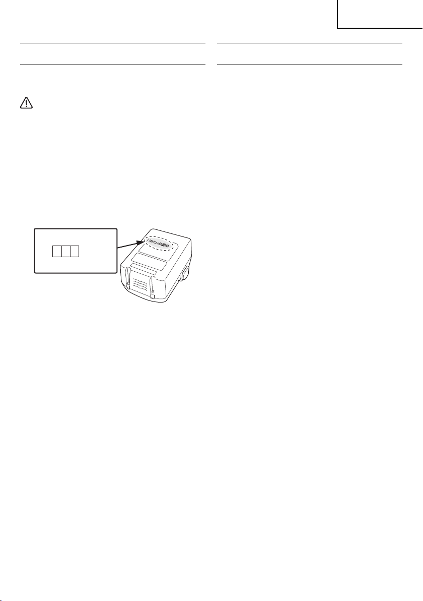
○
Do not place electrically conductive cuttings,
nails, steel wire, copper wire or other wire in the
storage case.
○
Either install the battery in the power tool or store
by securely pressing into the battery cover until
the ventilation holes are concealed to prevent
short-circuits (See Fig. 1).
8
Page 9
English
REGARDING LITHIUM-ION BATTERY
TRANSPORTATION
When transporting a lithium-ion battery, please observe
the following precautions.
WARNING
Notify the transporting company that a package
contains a lithium-ion battery, inform the company
of its power output and follow the instructions of the
transportation company when arranging transport.
●
Lithium-ion batteries that exceed a power output
of 100Wh are considered to be in the freight
classifi cation of Dangerous Goods and will
require special application procedures.
●
For transportation abroad, you must comply with
international law and the rules and regulations of
the destination country.
Power Output
Wh
2 to 3 digit number
Fig. 1
USB DEVICE CONNECTION
PRECAUTIONS
When an unexpected problem occurs, the data in a USB
device connected to this product may be corrupted or lost.
Always make sure to back up any data contained in the
USB device prior to use with this product.
Please be aware that our company accepts absolutely no
responsibility for any data stored in a USB device that is
corrupted or lost, nor for any damage that may occur to a
connected device.
SAVE THESE INSTRUCTIONS
AND
MAKE THEM AVAILABLE TO OTHER USERS
AND
OWNERS OF THIS TOOL!
9
Page 10
English
FUNCTIONAL DESCRIPTION
NOTE
The information contained in this Instruction Manual is designed to assist you in the safe operation and maintenance
of the power tool.
NEVER operate, or attempt any maintenance on the tool unless you have fi rst read and understood all safety
instructions contained in this manual.
Some illustrations in this Instruction Manual may show details or attachments that diff er from those on your own
power tool.
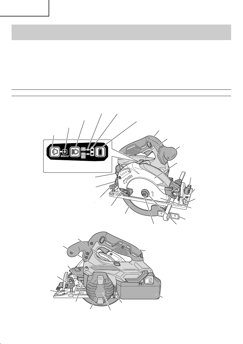
NAME OF PARTS
1. Cordless Circular Saw (C18DBAL)
Lighting mode indicator lamp
Lighting mode switch
Silent mode indicator lamp
Mode selector switch
Switch panel
Cutting depth lever
Incline wing-nut
Remaining battery indicator lamp
Remaining battery indicator switch
Lock-off button
Switch trigger
Sub handle
Saw cover
Incline lever
Base
10
Wing-bolt
Stopper lever
Nameplate
Lock lever
LED Light
Link
Housing
Wing-bolt
Lower guard lever
Motor
(Inside the Housing)
Lower guard
Left-hand bolt
Hex. bar wrench 5 mm
Fig. 2
Guide piece
Saw blade
Guide
Washer (B)
Handle
Battery
(optional accessories)
Page 11
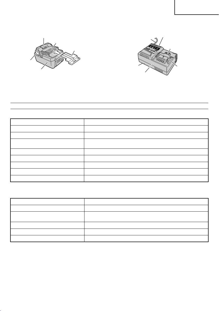
2. Battery (optional accessories) 3. Battery Charger (optional accessories)
English
Ventilation holes
Latch
Battery
Ter mi na ls
Battery cover
Body
Nameplate
Charge indicator lamp
Cord
Ventilation holes
Guide rail
<BSL1860> <UC18YSL3>
Fig. 3 Fig. 4
SPECIFICATIONS
1. Cordless Circular Saw
Model C18DBAL
Voltage 18 V
Motor DC brushless motor
No-load speed
4,100 /min (Power mode)
2,500 /min (Silent mode)
Blade Size 6-1/2" (165 mm) D × 5/8" (15.9 mm) H × 1/16" (1.6 mm) T
Max. Cutting Depth at 90° 2-19/32" (66 mm)
Max. Cutting Depth at 45° 1-49/64" (45 mm)
Max. Blade Angle Adjustable -5° – 45°
Weight (without battery) 6.0 lbs. (2.7 kg)
2. Battery Charger (optional accessories)
Model UC18YSL3
Input power source Single phase: AC 120 V 60 Hz
Charging time
(At a temperature of 68°F (20°C))
BSL1860 : Approx. 38 min
Charging voltage DC 14.4 – 18 V
Charging current DC 8.0 A
Weight 1.3 lbs. (0.6 kg)
NOTE: The charging time may vary according to temperature and power source voltage.
11
Page 12
English
Electronic control
○
Soft-start
○
Overload protection
This protection feature cuts off the power to the motor
in the event of overloading of motor or a conspicuous
reduction in rotational speed during operation.
When the overload protection feature has been
activated, the motor may stop.
In this case, release the tool switch and eliminate
causes of overloading.
After that you can use it again.
○
Overheat protection
This protection feature cuts off the power to the motor
and stops the power tool in the event of overheating of
motor during operation.
When the overheat protection feature has been
activated, the motor may stop.
In this case, release the tool switch and cool it down in
a few minutes.
After that you can use it again.
○
Rotation speed changeover function (Power mode /
Silent mode)
(Power mode / Silent mode switch function)
Each press of the Mode Selector Switch changes the
operating mode. (Fig. 5)
Mode selector switch
Silent mode indicator lamp
Silent mode reduces maximum motor RPM enabling
effi cient work with less noise.
The Silent Mode Indicator Lamp lights in Silent mode.
When the load increases during Silent mode, the tool
will automatically switch to Power mode and revert
back to Silent mode when the load decreases.
In Power mode, no change is made to Silent mode
even when the load decreases.
NOTE
○
To enable mode changes, pull the switch once after
installing the battery.
○
Do not give a strong shock to the switch panel or
break it. It may lead to a trouble.
Fig. 5
12
Page 13
ASSEMBLY AND OPERATION
English
APPLICATIONS
Cutting various types of wood.
○
REMOVAL AND INSTALLATION METHOD
OF BATTERY
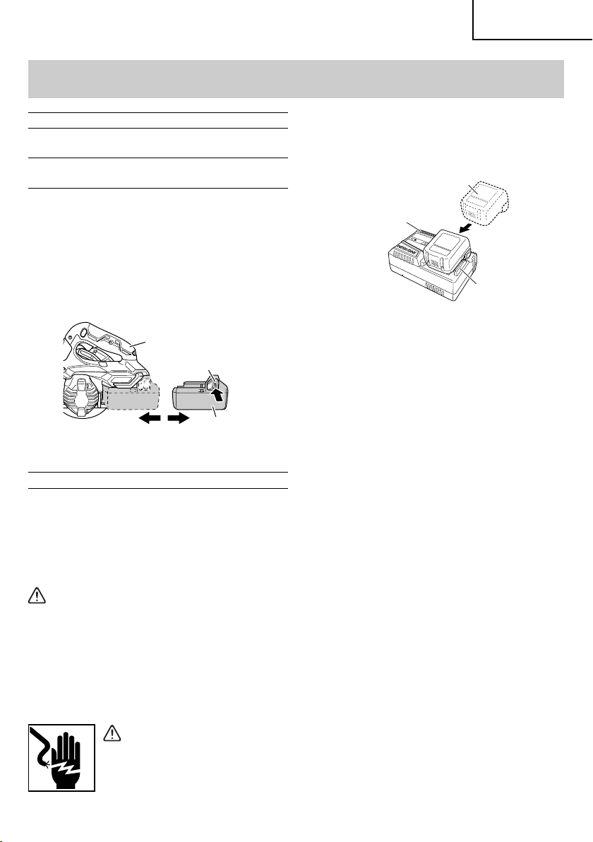
How to install the battery.
○
Align the battery with the groove in tool handle and
slip it into place.
Always insert it all the way until it locks in place with a
little click, If not, it may accidentally fall out of the tool,
causing injury to you or someone around you (Fig. 6).
○
How to remove the battery.
Withdraw battery from the tool handle while pressing
the latch (2 pcs) of the battery (Fig. 6).
Handle
Latch
Push
Battery
Pull outInsert
Fig. 6
CHARGING METHOD
NOTE
Before plugging into the receptacle, make sure the
following points.
○
The power source voltage is stated on the
nameplate.
○
The cord is not damaged.
2. Insert the battery to the battery charger.
Firmly Insert the battery into the battery charger as
shown in Fig. 7.
Battery
Charge indicator lamp
Guide rail
Fig. 7
3. Charging
When inserting a battery in the charger, the charge
indicator lamp will blink in blue.
When the battery becomes fully recharged, the
charge indicator lamp will light up in green.(See
Table 2)
(1) Charge indicator lamp indication
The indications of the charge indicator lamp will be
as shown in Table 2, according to the condition of the
battery charger or the battery.
WARNING
Do not charge at voltage higher than indicated
on the nameplate.
If charged at voltage higher than indicated on the
nameplate, the charger will burn out.
1. Connect the charger’s power cord to a receptacle.
When the power cord is connected, the charge
indicator lamp will blink in red. (At 1-second intervals)
WARNING
Do not use the electrical cord if
d am a ge d . H av e i t r ep ai r ed im m ed i at e ly .
13
Page 14
English
Before
charging
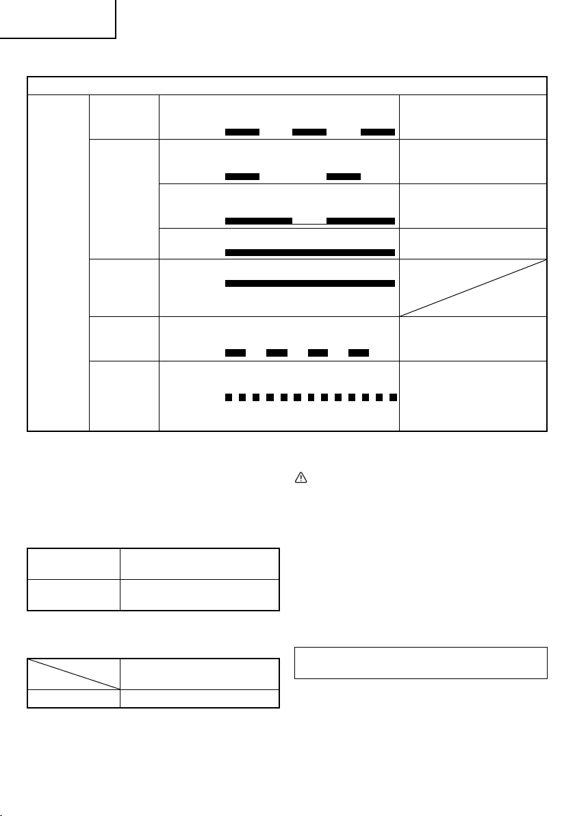
Table 2
Indications of the charge indicator lamp
Blinks
(RED)
Lights for 0.5 seconds. Does not light
for 0.5 seconds. (off for 0.5 seconds)
Plugged into power source
Lights for 0.5 seconds. Does not light
for 1 second. (off for 1 second)
Lights for 1 second. Does not light for
0.5 seconds. (off for 0.5 seconds)
While
charging
Blinks
(BLUE)
Blinks
(BLUE)
Charge
indicator
lamp
(RED /
BLUE /
GREEN /
PURPLE)
Charging
complete
Overheat
standby
Lights
(BLUE)
Lights
(GREEN)
Blinks
(RED)
Lights continuously
Lights continuously
(Continuous buzzer sound: about
6 seconds)
Lights for 0.3 seconds. Does not light
for 0.3 seconds. (off for 0.3 seconds)
Lights for 0.1 seconds. Does not light
Charging
impossible
Flickers
(PURPLE)
for 0.1 seconds. (off for 0.1 seconds)
(Intermittent buzzer sound: about
2 seconds)
(2) Regarding the temperature of the rechargeable
battery.
The temperatures for rechargeable batteries are
as shown in the Table 3, and batteries that have
become hot should be cooled for a while before being
recharged.
Table 3
Rechargeable
batteries
BSL1860
Temperatures at which the battery
can be recharged
14°F – 122°F
(-10°C – 50°C)
(3) Regarding recharging time (At 68°F (20°C))
Table 4 Charging time
Battery
Charger
UC18YSL3
BSL1860 Approx. 38 min.
NOTE
The recharging time may vary according to the
ambient temperature.
14
Battery capacity at less than
50%
Battery capacity at less than
80%
Battery capacity at more than
80%
Battery overheated. Unable
to charge. (Charging will
commence when battery cools)
Malfunction in the battery or the
charger
4. Disconnect battery charger from the receptacle.
CAUTION
Do not pull the plug out of the receptacle by
pulling on the cord.
Make sure to grasp the plug when removing from
receptacle to avoid damaging cord.
5. Remove the battery from the battery charger.
Supporting the battery charger with hand, pull out the
battery from the battery charger.
NOTE
Be sure to pull out the battery from the battery charger
after use, and then keep it.
Regarding electric discharge in case of new
batteries, etc.
As the internal chemical substance of new batteries
and batteries that have not been used for an extended
period is not activated, the electric discharge might
be low when using them the fi rst and second time.
This is a temporary phenomenon, and normal time
required for recharging will be restored by recharging
the batteries 2 – 3 times.
Page 15
English
How to make the batteries perform longer
(1) Recharge the batteries before they become
completely exhausted.
When you feel that the power of the tool becomes
weaker, stop using the tool and recharge its battery.
If you continue to use the tool and exhaust the electric
current, the battery may be damaged and its life will
become shorter.
(2) Avoid recharging at high temperatures.
A rechargeable battery will be hot immediately after
use. If such a battery is recharged immediately after
use, its internal chemical substance will deteriorate,
and the battery life will be shortened. Leave the
battery and recharge it after it has cooled for a while.
CAUTION
When the battery charger has been continuosly
●
used, the battery charger will be heated, thus
constituting the cause of the failures. Once the
charging has been completed, give 15 minutes
rest until the next charging.
●
If the battery is charged while it is heated
because it has been left for a long time in a
location subject to direct sunlight or because the
battery has just been used, the charge indicator
lamp of the charger lights for 0.3 seconds, does
not light for 0.3 seconds (off for 0.3 seconds). In
such a case, fi rst let the battery cool, then start
charging.
●
When the charge indicator lamp fl ickers (at
0.2–second intervals), check for and take out
any foreign objects in the charger’s battery
installation hole. If there are no foreign objects,
it is probable that the battery or charger is
malfunctioning. Take it to your authorized
Service Center.
PRIOR TO OPERATION
CAUTION
To avoid serious accident, ensure the switch is in
the OFF position, and pull out the battery.
1. Check the work area environment
Check the work area to make sure that it is clear of
debris and clutter.
Clear the area of unnecessary personnel. Ensure that
lighting and ventilation is adequate.
2. Mounting the Saw Blade (Fig. 8)
(1) Thoroughly remove any sawdust which has
accumulated on the spindle, bolt and washers.
(2) Apply quality machine oil to the surfaces of washers
(B) and (A) which come into contact with the blade.
(3) As shown in Fig. 8, one side of the saw blade should
be fi tted to the projecting center of washer (A) which
matches the blade’s inner diameter, and the other
side to the concave side of washer (B).
(4) To ensure that the saw blade rotates in the correct
direction, make sure the arrow on the saw blade
points in the same direction indicated by the arrow on
the saw cover.
(5) Using the fi ngers, tighten the left-hand bolt securing
the saw blade as much as possible. Then press the
lock button, lock the spindle, and fully tighten the lefthand bolt with the hex. wrench.
Left-hand bolt
Washer (B)
Concave
Spindle
Saw blade
Washer (A)
Fig. 8
CAUTION
After mounting the saw blade, reconfi rm that the
lock button is fi rmly secured in the prescribed
position.
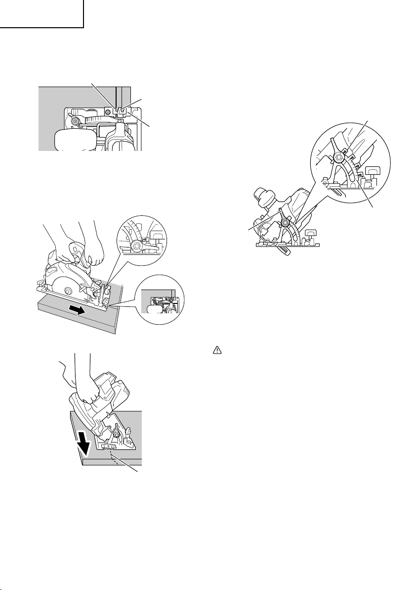
3. Dismounting the saw blade
CAUTION
Never touch the saw blade immediately after use.
The metal is hot and can easily burn your skin.
(1) Set the cutting volume at maximum, and place the
Circular Saw as shown in Fig. 9.
Hex. bar wrench 5 mm
Loosen
WARNING
If the left-hand bolt is worked using other tools
than the provided hex. wrench, excessive
tightening and insuffi cient tightening may take
place, resulting in injury.
Lock lever
Fig. 9
15
Page 16
English
(2) Depress the lock lever, lock the spindle, and remove
the left-hand bolt and washer (B) with the hex. bar
wrench 5 mm.
(3) While holding the lower guard lever to keep the lower
guard fully retracted into the saw cover, remove the
saw blade (Fig. 10).
Saw cover
Saw blade
Lower guard lever
Fig. 10
4. Check performance of lower guard
WARNING
Make absolutely sure that the lower guard is not
fi xed. Also, check and see if it can move smoothly.
If the saw blade is kept exposed, injury can result.
The lower guard (refer to Fig. 2) serves to protect your
body from coming into contact with the saw blade.
Make absolutely certain that the cover smoothly
performs to cover the saw blade. If the lower guard
should not move smoothly, never use it without
repairing it.
In such a case, get in touch with the store where you
bought the circular saw or the HITACHI AUTHORIZED
SERVICE CENTER for necessary repair.
5. Check for proper operation of the brake
This circular saw features an electric brake that
functions when the switch is released. Before using
the circular saw, ensure that the electric brake
functions properly. If it does not, bring the tool to a
HITACHI AUTHORIZED SERVICE CENTER.
6. Prepare a wooden work bench (Fig. 11)
Since the saw blade will extend beyond the lower
surface of the lumber, place the lumber on a work
bench when cutting. If a square block is utilized
as a work bench, select level ground to ensure it is
properly stabilized. An unstable work bench will result
in hazardous operation.
BaseLumber
CAUTION
To avoid possible accident, always ensure that
the portion of lumber remaining after cutting is
securely anchored or held in position.
7. Check battery insertion
WARNING
If the battery is inserted while the power switch
is in the ON position, the power tool will start
operating immediately, inviting serious accident.
CAUTION
Until the battery locks in place with a little click,
if not, it may accidentally fall out of the tool
causing injury to you or someone around you.
ADJUSTING THE SAW PRIOR TO USE
CAUTION
Pull out battery before doing any adjusting.
1. Adjusting the cutting depth (Fig. 12)
WARNING
If the lever is loose, injury can result. Tighten it
securely after adjustment.
To adjust cutting depth, loosen the cutting depth lever
and, while holding the base with one hand, move
the main body up and down to obtain the prescribed
cutting depth.
After adjusting to the prescribed cutting depth, tighten
the cutting depth lever securely.
Loosen
Tighten
Cutting depth lever
Base
Fig. 12
2. Adjusting the angle of inclination
WARNING
If the wing-nut is loose, injury can result. Tighten
it securely after adjustment.
Work bench
16
Saw blade
Fig. 11
You can incline saw blade from -5° to a maximum
angle of 45° in relation to the base.
As shown in Fig. 13 by loosening the incline lever
on the inclined gauge and incline wing-nut, the saw
blade may be inclined to a maximum angle of 45° in
relation to the base.
Page 17
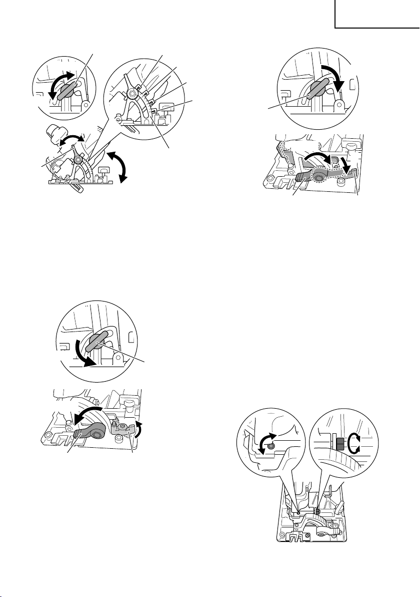
English
Incline wing-nut
Tighten
45°
30°
15°
Loosen
15
0
0°
30
Tighten
Loosen
Inclined gauge
Incline
lever
Fig. 13
To use at an angle of -5°, fi rst loosen the cutting depth
lever and minimize the cutting depth of the saw blade.
Next, loosen the incline lever and the incline wing-nut,
turning the stopper lever in the direction indicated as A
(Fig.14). Tilting the main unit in the direction indicated
as B, fasten the unit with the incline lever and incline
wing-nut (Fig. 15).
Loosen
Incline wing-nut
Loosen
Tighten
Incline wing-nut
Tighten
B
Incline lever Stopper lever
Fig. 15
Always ensure that the wing-nut is thoroughly
tightened after making the desired adjustment.
NOTE
Values of the inclined gauge provided on the base
merely serve as a rough guideline. For cutting
operation at an inclined precise angle, use the circular
saw after adjusting the angle between the base and
the saw blade with a protractor, etc.
3. Fine tuning of parallelism
It is possible to fi ne-tune the parallelism of the saw
blade to the base using the parallelism adjustment
screw.
Adjustment has already been made at the time of
shipment from the factory. However, in the unlikely
event of parallelism being faulty, adjust as follows.
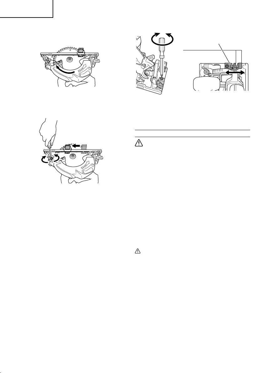
(1) Unfasten only the mounting screws of the saw cover
hinge portion (Fig. 16).
Incline lever
A
Stopper lever
Fig. 14
5
Fig. 16
17
Page 18
English
(2) Retract the lower guard into the saw cover.
(3) Insert wood chip in the rear side of the saw blade
base, and mark the position on the base (Fig. 17).
Fig. 17
(4) Move the marked wood chip to the front of the base,
and turn the parallelism adjustment screw so that the
marking corresponds to the base side (Fig. 18).
Fig. 18
NOTE
After parallelism adjustment, if the saw cover hinge
portion is loose, tighten the M5 U-Nut. Do not over
tighten the nut as this may result in deformation of the
bevel plate.
(5) After adjustment, fasten the mounting screws tightly
in place.
Guide piece
Fig. 19
Loosen the fi xed M4 screw on the guide piece, should
the fi xing position be wrong, and make necessary
adjustment of the position.
OPERATION
WARNING
●
Never touch the moving parts.
●
Never operate the circular saw with the saw
blade turned upward or to the side.
●
Do not fi x and secure the lock-off button.
Besides, keep your fi nger off the switch trigger
when the circular saw is being carried around.
Otherwise, the main body switch can be
inadvertently turned ON, resulting in unexpected
accidents.
●
Keep the light ON during cutting operation only.
If it is lit ON in other cases, the main body switch
can be inadvertently turned ON, resulting in
unexpected accidents.
●
Do not use any abrasive wheels.
●
Use only blade diameter specifi ed on the product
nameplate.
NOTE
Parallelism may be slightly faulty if the cutting depth is
adjusted after parallelism adjustment.
4. Adjusting the guide piece
On the circular saw, it is possible to make fi ne
adjustment of the fi xing position of the guide piece,
where the saw blade and the premarked line are to be
aligned.
When the saw is shipped from the factory, the linear
portion of a front scale on the guide piece is aligned
with the central position of the saw blade (Fig. 19).
18
CAUTION
Don’t remove circular saw from workpiece during
●
a cut while the saw blade is moving.
●
Pull out the battery after completing operation.
●
Do not look directly into the light from the LED
light. Continuous and direct exposure to the light
from the LED light can injure your eyes.
●
To extend the lifetime, the lithium-ion battery
equips with the protection function to stop the
output. Therefore, if the tool is overloaded, the
motor may stop. However, this is not the trouble
but the result of protection function. In this case,
release the switch of tool and eliminate the
causes of overloading.
●
Before use, check to see if the lock-off button
moves smoothly.
Page 19
English
NOTE
Take care not to lock the motor. If the motor is locked,
immediately turn the power off . If the motor is locked
for a while, the motor or battery may be burnt.
1. Check if saw blade is tightened
While the saw blade is tightened securely for
immediate use when it is assembled at the factory,
be sure to check it out again for caution’s sake. A
bolt can be tightened when it is turned clockwise.
Use the provided hex. bar wrench 5 mm to check it
out. For further details, refer to the item of [PRIOR TO
OPERATION] on Page 15.
2. Check if the lever is tightened
If the lever to adjust cutting depth (Fig. 12) is loose,
injury can result. Make sure that it is tightened
securely.
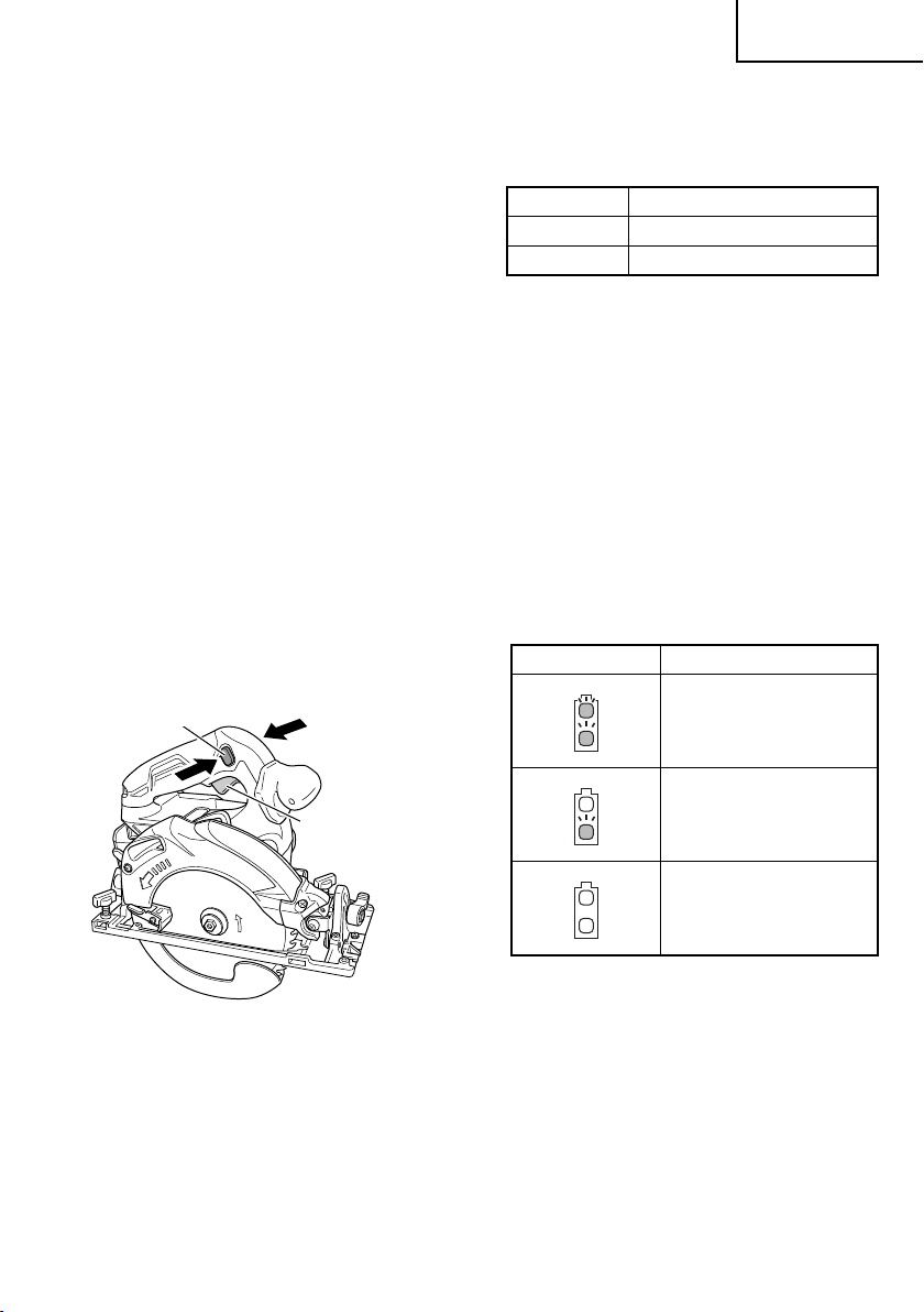
3. Operation of switch (Fig. 20)
(switch trigger and light switch)
For safe operation of the machine, a “lock-off button”
is provided on the side of a handle.
If the “switch trigger” is pulled in a state where “lock-
off button” is pressed in the direction of the arrow
mark, the main switch can be turned ON.
After the switch is on, the saw blade will continue to
operate as long as you pull on the switch trigger, even
if you release the lock-off button. Also, the LED light
will remain lit for Always-ON mode as well as during
SW interlocked mode.
Lock-off button
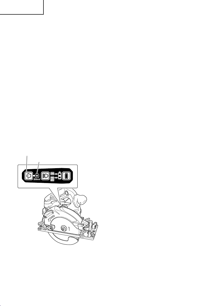
Additionally, if the load decreases again, it
automatically returns to Silent mode.
In Power mode, no change is made to Silent mode
even when the load decreases.
Mode No-load speed
Power 4,100 /min
Silent 2,500 /min
NOTE
●
The mode will only change after a battery is installed
and the switch is pulled once.
●
The current mode will be maintained even if the switch
is on/off , or the battery is removed/reinserted.
5. About Remaining Battery Indicator
When pressing the remaining battery indicator switch,
the remaining battery indicator lamp lights and the
battery remaining power can be checked. When
releasing your fi nger from the remaining battery
indicator switch, the remaining battery indicator lamp
goes off . The Table 4 shows the state of remaining
battery indicator lamp and the battery remaining
power.
Table 4
State of lamp Battery Remaining Power
The battery remaining power
is enough.
Switch trigger
Fig. 20
4. About the mode select function
Each time the mode selector switch is pushed, the
operation mode changes.
When Silent mode is selected, the Silent mode
indicator lamp lights up.
Silent mode reduces maximum motor RPM enabling
effi cient work with less noise.
If the load increases while the motor is operating in
Silent mode, it automatically changes to Power mode.
The battery remaining power
is a half.
The battery remaining power
is nearly empty.
Re-charge the battery
soonest possible.
As the remaining battery indicator shows somewhat
diff erently depending on ambient temperature and
battery characteristics, read it as a reference.
NOTE
To save the battery power consumption, the
remaining battery indicator lamp lights while pressing
the remaining battery indicator switch.
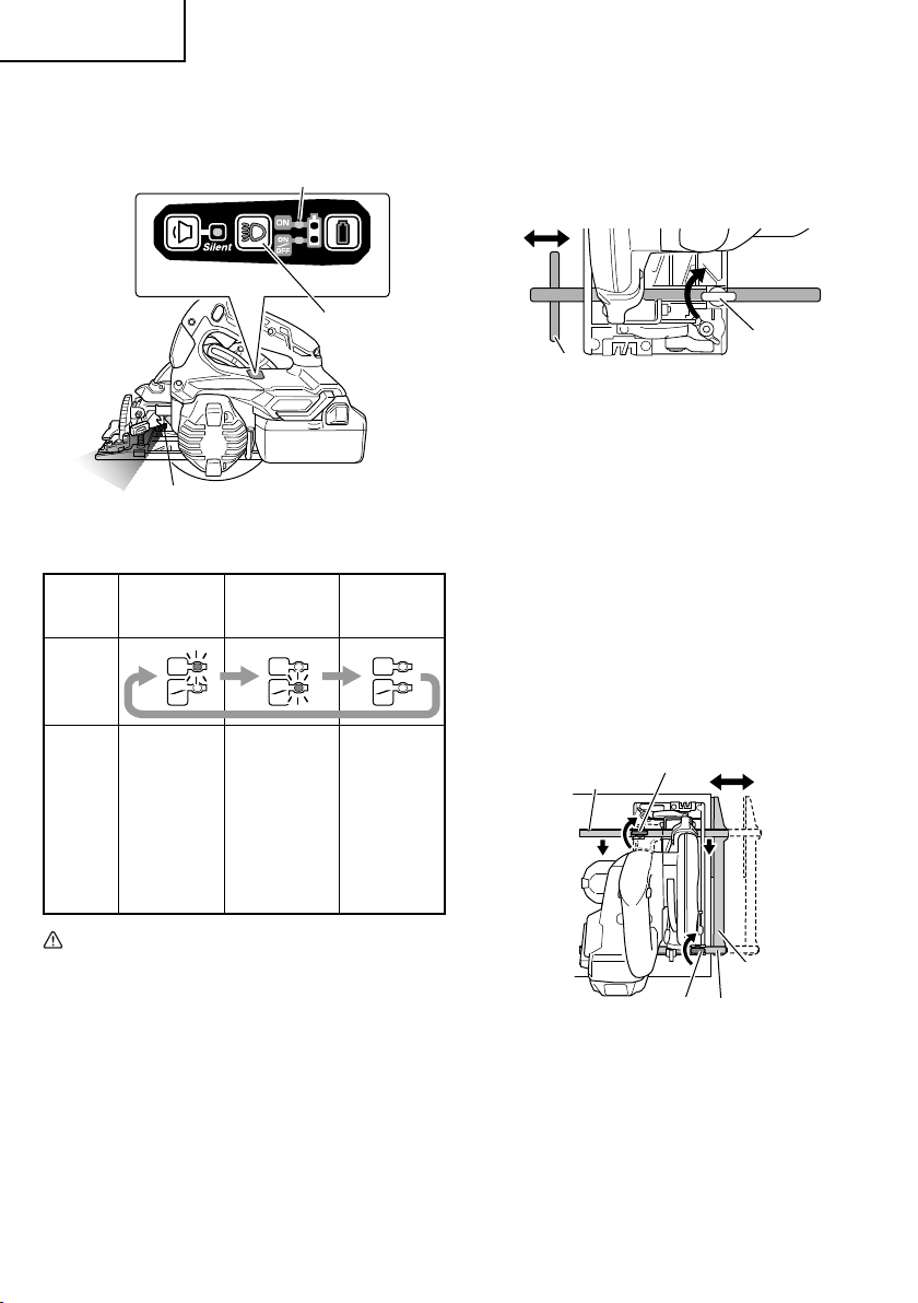
6. How to use the LED light
By pressing the light selector switch on the switch
panel, the LED light mode changes as Table 5. It is
indicated by green lamp. (Fig. 21)
19
Page 20
English
To prevent the battery power consumption, turn off the
LED light frequently.
Remaining battery indicator lamp
Switch panel
Light section
switch
LED Light
Fig. 21
Table 5
Always-ON
mode
SW
interlocked
Always-OFF
mode
mode
Panel
display
ON
ON
OFF
Always ON
(turn off after
2 minutes)
ON
ON
OFF
Light only
SW-ON
(Automatically
ON
ON
OFF
Always OFF
goes out
State
approximately
10 seconds
after the
switch is
released)
7. Attaching the guide (sold separately)
Slide the guide through the front hole on the side of
the base (the cut- off side). Move the guide to the right
or left to adjust the cutting position, and tighten the
wing-bolt at the front to fasten the guide.
Wing-bolt
Guide
Fig. 22
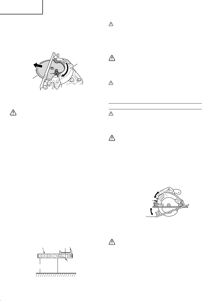
8. Attaching the long guide (sold separately)
You can cut at a greater degree of parallel angle
against the end face of materials than the regular
guide.
When using the long guide, use the wing-bolts at the
front and rear.
(1) Normal installation
a) Slide the front and rear guide bars through the
holes on the base side and move the long guide to
the right or left to adjust the cutting position.
b) Press the front guide bar against the indicated
direction and tighten the front wing-bolt. Then,
tighten the rear wing-bolt to fasten the guide bar.
c) Lay the front of the long guide along the material to
cut.
Front guide bar
Front wing-bolt
CAUTION
Wipe off any dirt or grime attached to the lens of
the LED light with a soft cloth, being careful not
to scratch the lens.
Scratches on the lens of the LED light can result
in decreased brightness.
NOTE
To prevent the battery power consumption caused by
forgetting to turn off the LED light, the light goes off
automatically in about 2 minutes.
20
Long guide
Rear wing-bolt
Rear guide bar
Fig. 23
(2) Installation to the housing side
Use by re-installing the two front and rear guide bars.
a) Remove the two screws of the long guide.
b) With the protrusions of the long guide pointing
downwards, re-attach the two guide bars.
Page 21
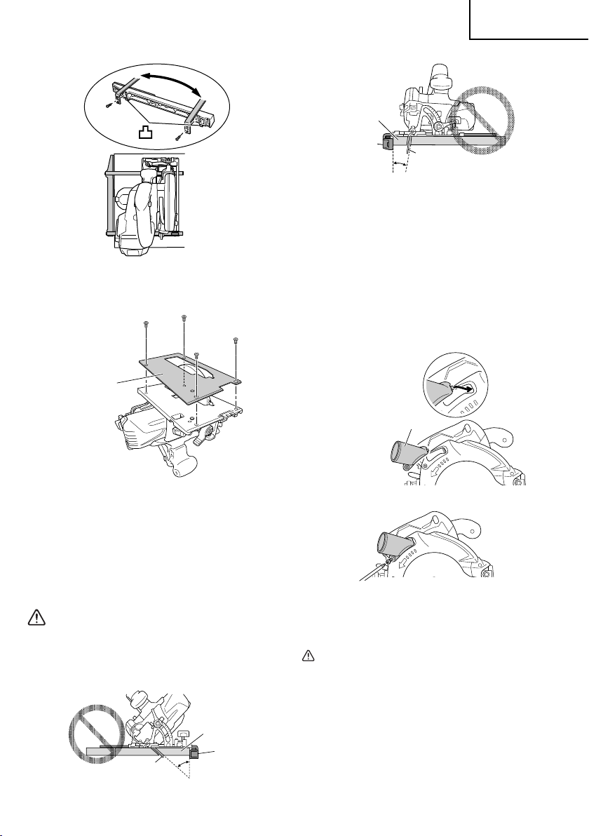
Fig. 24
9. Attaching the fl uorine plate (sold separately)
Firmly fi x to the base with the bolts.
Fluorine plate
English
Lumber
Guide
Saw blade
Fig. 27
10. Attaching the dust collection adapter (sold separately)
When connecting with a dust extractor, attach the
dust collection adapter to the chip exhaust. When
connecting to the dust extractor, a hose with an
inside diameter of φ25 mm can be used for the dust
extractor.
Insert the catch of the dust collection adapter to the
front part of the chip exhaust, and fasten the dust
collection adapter with the M4 screw that is included
with the unit.
Dust collection adapter
Fig. 25
NOTE
●
The maximum cutting depth will be 2.5 mm shallower.
●
Cutting anything other than wood will remove the
fl uorine, making the base diffi cult to slide.
●
The fl uorine coating of the base surface makes it
easier to slide, making the motor susceptible to
pressure. Do not press too hard on the unit.
WARNING
When using the guide, avoid inclined cutting that
will allow the cut material to be caught between
the saw blade and the guide. Doing so may result
in injury.
Lumber
Guide
Saw blade
Fig. 26
Fig. 28
Fig. 29
11. Cutting procedures
CAUTION
Recheck that the saw blade is securely clamped.
●
●
Confi rm that the lever for adjusting the slot
depth, the wing-nut for adjusting the angle of
inclination.
21
Page 22
English
(1) Place the base on the material, then align the
premarked line and the saw blade with the notch at
the front of the base (Fig. 30).
45°
0°
Guide piece
Fig. 30 <Top View>
(2) When the base is not inclined, use the right side of the
notch (Fig. 30, Fig. 31).
If the base is inclined (45 degrees), use the left side of
the notch (Fig. 30, Fig. 32).
30
15
Fig. 31
Cutting line
(at 45 degrees)
Fig. 32
NOTE
When using the saw at the inclination of 45 degrees,
use both the marks of on the bevel plate and [45] on
the inclined gauge of the base (Fig. 33).
What’s more, if it is absolutely essential to use the
saw at a precise angle, make adjustment using a
protractor, etc.
Bevel plate
30
15
0
Inclined gauge
Incline lever
Fig. 33
(3) Ensure that the switch is turned to the ON position
before the saw blade comes in contact with the
lumber. The switch is turned ON when the switch
trigger is squeezed; and OFF when the switch trigger
is released. Moving the saw straight at a constant
speed will produce optimum cutting.
CAUTION
Before starting to saw, ensure that the saw blade
●
has reached full speed revolution.
●
Should the saw blade be stopped or made an
abnormal noise during operation, turn off the
switch immediately.
●
When fi nished with a job, pull out the battery
from the main body.
●
To avoid abnormal heating of the blade tip or
damage to the saw blade, do not twist or apply
excessive force to the saw blade when cutting.
Let the blade move forward smoothly.
●
In the situation where the circular saw is
continuously operated while replacing the
battery with stocked spare batteries one after
another, the motor tends to overheat. Therefore,
whenever the housing becomes hot, give the saw
a break for a while.
●
Avoid cutting operation in a state where the base
bottom is afl oat from the material being cut.
Otherwise, the motor can get locked.
22
Page 23
MAINTENANCE AND INSPECTION
WARNING
Be sure to turn off the switch and pull out the battery before doing any inspection or maintenance.
English
1. Inspecting the saw blade
Continued use of a dull or damaged blade will result in
reduced cutting effi ciency and may cause overloading
of the motor. Replace the blade with a new one as
soon as excessive abrasion is noted.
CAUTION
If a dull saw blade is used, reactive force is
increased during cutting operation. Avoid the
use of the dull saw blade without repair.
2. Check the Screws
Loose screws are dangerous. Regularly inspect them
and make sure they are tight.
CAUTION
Using this power tool with loosen, screws is
extremely dangerous.
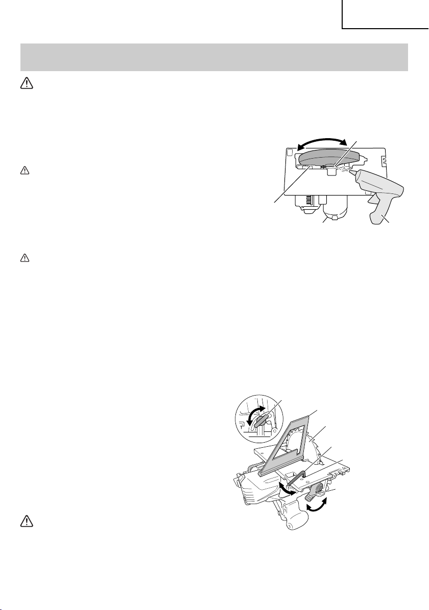
3. Motor unit maintenance
The motor winding is an important part of this tool.
Avoid damaging and be careful to avoid contact with
cleaning oil or water.
After 50 hours of use, clean the motor by blowing into
the ventilation holes of the motor housing with dry air
from an air gun or other tool (Fig. 34).
Dust or particle accumulation in the motor can result
in damage.
4. Inspecting and maintaining the lower guard
Always make sure that the lower guard moves
smoothly.
In the event of any malfunction, immediately repair the
lower guard.
For cleaning and maintenance, use an air gun or other
tool to blow clean the space between the lower guard
and gear cover as well as the rotation part of the lower
guard with dry air (Fig. 34).
Doing so is eff ective for the emission of chips or other
particles.
Accumulation of chips or other particles around the
lower guard may result in malfunction or damage.
Ensure smooth
movement of
lower guard
Space between lower
guard and gear cover
Housing vent
Fig. 34
5. Clean inside the saw cover
Periodically inspect and clean the saw cover to
ensure that there is no accumulation of chips or other
particles.
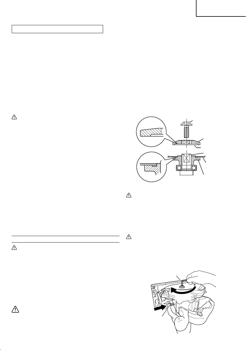
6. Adjusting the base and saw blade to maintain
perpendicularity (Fig. 35)
The angle between the base and the saw blade
has been adjusted to 90°, however should this
perpendicularity be lost for some reason, adjust in the
following manner.
(1) Loosen the incline lever and incline wing-nut, place
the square on the base and against the saw blade to
attain a right angle, and lightly tighten the incline lever.
Incline wing-nut
Rotation part of
the lower guard
Air gun
Square
Saw blade
Hex. bar
wrench 2.5 mm
Adjusting screw
Incline lever
WARNING
To prevent dust inhalation or eye irritation, wear
protective safety goggles and a dust mask when
using an air gun or other tool to clean the lower
guard, ventilation holes or other parts of the
product.
Fig. 35
23
Page 24

English
(2) Using the included 2.5 mm hex. bar wrench, turn the
adjusting screw until its tip touches the metal part of
the base, and then fi rmly tighten the incline lever and
incline wing-nut.
7. Check for dust
Dust may be removed with a clean rag or a cloth
dampened with soapy water.
Do not use bleach, chlorine, gasoline or thinner, for
they may damage the plastics.
8. Lubrication
The bearings in this tool have been suffi ciently
lubricated with quality lubricating oil, taking into
account the expected life of this tool under normal
operating conditions. As a result, no further lubrication
is necessary.
9. Disposal of the exhausted battery
WARNING
Do not dispose of the exhausted battery. The
battery may explode if it is incinerated. The
battery is recyclable. At the end of it’s useful
life, under various state and local laws, it may
be illegal to dispose of this battery into the
municipal waste stream. Check with your local
solid waste offi cials for details in your area for
recycling options or proper disposal.
10. Storage
Storing in a place below 104°F (40°C) and out of the
reach of children.
NOTE
Storing lithium-ion batteries
Make sure the lithium-ion batteries have been fully
charged before storing them.
Prolonged storage (3 months or more) of batteries with
a low charge may result in performance deterioration,
signifi cantly reducing battery usage time or rendering
the batteries incapable of holding a charge.
However, signifi cantly reduced battery usage time
may be recovered by repeatedly charging and using
the batteries two to fi ve times.
If the battery usage time is extremely short despite
repeated charging and use, consider the batteries
dead and purchase new batteries.
11. Service and repairs
All quality power tools will eventually require servicing
or replacement of parts because of wear from normal
use. To assure that only genuine replacement
parts must be used, all service and repairs must be
performed by a HITACHI AUTHORIZED SERVICE
CENTER, ONLY.
12. Service parts list
CAUTION
Repair, modifi cation and inspection of Hitachi
Power Tools must be carried out by a Hitachi
Authorized Service Center.
This Parts List will be helpful if presented with
the tool to the Hitachi Authorized Service Center
when requesting repair or other maintenance.
In the operation and maintenance of power tools,
the safety regulations and standards prescribed
in each country must be observed.
MODIFICATIONS:
Hitachi Power Tools are constantly being improved
and modifi ed to incorporate the latest technological
advancements.
Accordingly, some parts may be changed without
prior notice.
Important notice on the batteries for the Hitachi
cordless power tools
Please always use one of our designated genuine
batteries. We cannot guarantee the safety and
performance of our cordless power tool when used
with batteries other than these designated by us,
or when the battery is disassembled and modifi ed
(such as disassembly and replacement of cells or
other internal parts).
24
Page 25

English
ACCESSORIES
WARNING
ALWAYS use Only authorized HITACHI replacement parts and accessories. Never use replacement parts
or accessories which are not intended for use with this tool. Contact HITACHI if you are not sure whether
it is safe to use a particular replacement part or accessory with your tool.
The use of any other attachment or accessory can be dangerous and could cause injury or mechanical
damage.
NOTE
Accessories are subject to change without any obligation on the part of the HITACHI.
STANDARD ACCESSORIES
1
Saw Blade (mounted on tool) .............................................................1
C18DBAL
(NN)
OPTIONAL ACCESSORIES ... SOLD separately
1. Battery (BSL1860) (Code No. 338890)
2. Battery charger (UC18YSL3)
3. Battery cover (Code No. 329897)
4. Saw Blade Use ... Cutting various types of wood.
External
Dia.
6-1/2"
(165 mm)
Hole
Dia.
5/8"
(15.9 mm)
1
External Dia. Hole Dia. Code No.
6-1/2" (165 mm) 5/8" (15.9 mm) 372983
2
Hex. bar wrench 5 MM (Code No. 944459) (mounted on tool) ............1
3
Hex. bar wrench 2.5 MM (Code No. 990666) ......................................1
4
Guide (Code No. 302756) ...................................................................1
Battery, battery charger and battery cover are not contained.
No. of
teeth
24 Pieces 372983
Code
No.
2
3
5. Long guide (Code No. 316161)
6. Dust collection adapter (Code No. 339383)
7. Fluorine plate (Code No. 339188)
4
NOTE
Specifi cations are subject to change without any
obligation on the part of the HITACHI.
25
Page 26

Français
INFORMATIONS IMPORTANTES DE SÉCURITÉ
Lire et comprendre toutes les précautions de sécurité, les avertissements et les instructions de fonctionnement dans ce
mode d’emploi avant d’utiliser ou d’entretenir cet outil motorisé.
La plupart des accidents causés lors de l’utilisation ou de l’entretien de l’outil motorisé proviennent d’un non respect des
règles ou précautions de base de sécurité. Un accident peut la plupart du temps être évité si l’on reconnaît une situation
de danger potentiel avant qu’elle ne se produise, et en observant les procédures de sécurité appropriées.
Les précautions de base de sécurité sont mises en évidence dans la section “SECURITE” de ce mode d’emploi et dans
les sections qui contiennent les instructions de fonctionnement et d’entretien.
Les dangers qui doivent être évités pour prévenir des blessures corporelles ou un endommagement de la machine sont
identifi és par AVERTISSEMENTS sur l’outil motorisé et dans ce mode d’emploi.
NE JAMAIS utiliser cet outil motorisé d’une manière qui n’est pas spécifi quement recommandée par HITACHI.
SIGNIFICATION DES MOTS D’AVERTISSEMENT
AVERTISSEMENT indique des situations potentiellement dangereuses qui, si elles sont ignorées, pourraient entraîner
la mort ou de sérieuses blessures.
PRECAUTION indique des situations dangereuses potentilles qui, si elles ne sont pas évitées, peuvent entraîner de
mineures et légères blessures ou endommager la machine.
REMARQUE met en relief des informations essentielles.
SECURITE
AVERTISSEMENTS DE SÉCURITÉ GÉNÉRAUX CONCERNANT LES OUTILS
ÉLECTRIQUES
AVERTISSEMENT
Lire tous les avertissements de sécurité et toutes les instructions
Tout manquement à observer ces avertissements et instructions peut engendrer des chocs électriques, des
incendies et/ou des blessures graves.
Conservez tous les avertissements et toutes les instructions pour vous y référer ultérieurement.
Le terme “outil électrique”, utilisé dans les avertissements, se réfère aux outils électriques (câblé) ou aux outils à
piles (sans fi l).
1) Sécurité de l’aire de travail
a) Maintenir l’aire de travail propre et bien
éclairée.
Les endroits encombrés ou sombres sont
propices aux accidents.
b) Ne pas utiliser d’outils électriques en présence
de liquides, gaz ou poussière infl ammables,
au risque de provoquer une explosion.
Les outils électriques créent des étincelles
susceptibles d’enfl ammer la poussière.
c) Ne pas laisser les enfants et les visiteurs
s’approcher de vous lorsque vous utiliser un
outil électrique.
Les distractions peuvent faire perdre le contrôle.
2) Sécurité électrique
a) Les prises de l’outil électrique doivent
correspondre à la prise secteur.
Ne jamais modifi er la prise.
Ne pas utiliser d’adaptateurs avec les outils
électriques mis à la masse.
26
Les prises non modifi ées et les prises secteurs
correspondantes réduisent les risques de choc
électrique.
b) Eviter tout contact avec les surfaces mises
à la masse telles que les tuyaux, radiateurs,
bandes et réfrigérateurs.
Le risque de choc électrique est accru en cas de
mise à la masse du corps.
c) Ne pas exposer les outils électriques à la
pluie ou à des conditions humides.
Si l’eau pénètre dans l’outil, cela augmente les
risques de choc électrique.
d) Ne pas utiliser le cordon à tort. Ne jamais
utiliser le cordon pour transporter ou
débrancher l’outil électrique.
Maintenir le cordon loin de la chaleur, de
l’huile, des bords pointus ou des pièces
mobiles.
Les cordons endommagés ou usés augmentent
les risques de choc électrique.
Page 27

Français
e) En cas d’utilisation d’un outil électrique à
l’extérieur, utiliser un cordon de rallonge
adapté à un usage extérieur.
L’utilisation d’un cordon adapté à l’usage extérieur
réduit les risques de choc électrique.
f) Si vous devez utiliser un outil électrique dans
un endroit humide, utilisez une alimentation
protégée contre les courants résiduels.
L’utilisation d’un dispositif de protection contre
les courants résiduels réduit le risque de choc
électrique.
3) Sécurité personnelle
a) Restez alerte, regarder ce que vous faites et usez
de votre bon sens en utilisant un outil électrique.
Ne pas utiliser d’outil électrique si vous êtes
sous l’infl uence de drogues, d’alcool ou de
médicaments.
Pendant l’utilisation d’outils électrique, un instant
d’inattention peut entraîner des blessures graves.
b) Utiliser un équipement de protection
individuelle. Toujours porter des verres de
protection.
L’utilisation d’équipements de protection tels
que les masques anti-poussière, les chaussures
de sécurité anti-dérapantes, les casques ou
les protections auditives dans des conditions
appropriées réduisent les risques de blessures.
c) Empêcher les démarrages intempestifs.
Veiller à ce que l’interrupteur soit en
position d’arrêt avant de brancher à une
source d’alimentation et/ou une batterie, de
ramasser l’outil au sol ou de le transporter.
Transporter les outils électriques avec le doigt sur
l’interrupteur ou brancher les outils électriques
avec l’interrupteur en position de marche peut
entraîner des accidents.
d) Retirer toute clé de sécurité ou clé avant de
mettre l’outil électrique en marche.
Laisser une clé ou une clé de sécurité sur une
partie mobile de l’outil électrique peut engendrer
des blessures.
e) Ne pas trop se pencher. Toujours garder une
bonne assise et un bon équilibre pendant le
travail.
Cela permet un meilleur contrôle de l’outil
électrique dans des situations imprévisibles.
f) Porter des vêtements adéquats. Ne pas porter
de vêtements amples ni de bijoux. Maintenir
les cheveux, les vêtements et les gants loin
des pièces mobiles.
Les vêtements amples ou les cheveux longs
peuvent se prendre dans les pièces mobiles.
g) En cas de dispositifs destinés au
raccordement d’installations d’extraction et
de recueil de la poussière, veiller à ce qu’ils
soient correctement raccordés et utilisés.
L’utilisation d’un dispositif de collecte de la
poussière peut réduire les dangers associés à la
poussière.
4) Utilisation et entretien d’un outil électrique
a) Ne pas forcer sur l’outil électrique. Utiliser
l’outil électrique adapté à vos travaux.
Le bon outil électrique fera le travail mieux et en
toute sécurité au régime pour lequel il a été conçu.
b) Ne pas utiliser l’outil électrique si l’interrupteur
ne le met pas en position de marche et d’arrêt.
Tout outil ne pouvant être contrôlé par l’interrupteur
est dangereux et doit être réparé.
c) Débrancher la prise ou retirer la batterie avant
de procéder à des réglages, au remplacement
des accessoires ou au stockage des outils
électriques.
Ces mesures préventives de sécurité réduisent
les risques de démarrage accidentel de l’outil
électrique.
d) Stockez les outils électriques inutilisés hors
de la portée des enfants et ne pas laisser des
personnes non familiarisées avec l’outil ou
ces instructions utiliser l’outil électrique.
Les outils électriques sont dangereux entre les
mains d’utilisateurs non habilités.
e) Entretenir les outils électriques. Vérifi er
l’absence de mauvais alignement ou d’arrêt,
d’endommagement de pièces ou toute autre
condition susceptible d’aff ecter l’opération
de l’outil.
Si l’outil est endommagé, le faire réparer
avant utilisation.
De nombreux accidents sont dus à des outils mal
entretenus.
f) Maintenir les outils coupants aiguisés et
propres.
Des outils coupants bien entretenus avec des
bords aiguisés sont moins susceptibles de se
coincer et plus simples à contrôler.
g) Utiliser l’outil électrique, les accessoires et
les mèches de l’outil, etc. conformément à ces
instructions en tenant compte des conditions
d’utilisation et du travail à réaliser.
L’utilisation de l’outil électrique pour des
opérations diff érentes de celles pour lesquelles il
a été conçu est dangereuse.
5) Utilisation et entretien de la batterie
a) Recharger la batterie uniquement avec le
chargeur recommandé par le fabricant.
Un chargeur inadéquat pour le type de batterie
peut entraîner un risque d’incendie en cas
d’utilisation avec une autre batterie.
b) Utiliser les outils électriques uniquement
avec les batteries spécifi ées.
27
Page 28

Français
L’utilisation d’autres batteries peut entraîner un
risque de blessures et d’incendie.
c) Lorsque la batterie est inutilisée, la garder
à l’écart d’objets métalliques comme des
trombones, des pièces de monnaie, des clés,
des clous, des vis ou autres petits objets
métalliques pouvant raccorder les bornes.
La connexion des bornes peut entraîner des
blessures ou un incendie.
d) En cas d’utilisation dans des conditions
extrêmes, du liquide peut être émis de la
batterie. Éviter tout contact. en cas de contact
accidentel, rincer à l’eau. Si le liquide entre en
contact avec les yeux, consulter un médecin.
Le liquide émis par la batterie peut entraîner des
irritations et des brûlures.
6) Service
a) Faire entretenir l’outil électrique par un
technicien habilité à l’aide de pièces de
rechange identiques exclusivement.
Cela garantira le maintien de la sécurité de l’outil
électrique.
– AVERTISSEMENT –
Pour réduire tout risque de blessure, l’utilisateur
doit lire le mode d’emploi.
AVERTISSEMENT:
La poussière résultant d’un ponçage, d’un sciage,
d’un meulage, d’un perçage ou de toute autre activité
de construction renferme des produits chimiques
qui sont connus par l’Etat de Californie pour causer
des cancers, des défauts de naissance et autres
anomalies de reproduction. Nous énumérons cidessus certains de ces produits chimiques:
●
Plomb des peintres à base de plomb,
●
Silice cristalline des briques et du ciment et autres
matériaux de maçonnerie, et
●
Arsenic et chrome du bois d’oeuvre traité
chimiquement.
Le risque d’exposition à ces substances varie en
fonction de la fréquence d’exécution de ce genre
de travail. Pour réduire l’exposition à ces produits
chimiques, travailier dans un lieu bien ventilé, et porter
un équipement de protection agréé, par exemple un
masque anti-poussière spécialement conçu pour fi lter
les particules microscopiques.
AVERTISSEMENTS DE SÉCURITÉ
RELATIFS À LA SCIE CIRCULAIRE
Procédures de coupe
a) DANGER: N’approchez pas les mains de la
zone de coupe et de la lame. Gardez la deuxième
main sur la poignée auxiliaire ou sur le boîtier du
moteur.
28
Si les deux mains tiennent la scie, elles ne peuvent
pas être coupées par la lame.
b) N’exposez aucune partie de votre corps sous la
pièce à travailler.
Le protecteur ne peut pas vous protéger de la lame
sous la pièce à travailler.
c) Ajustez la profondeur de coupe à l’épaisseur de
la pièce à travailler.
Il convient que moins de la totalité d’une dent parmi
toutes les dents de la lame soit visible sous la pièce à
travailler.
d) Ne tenez jamais la pièce à débiter dans vos
mains ou sur vos jambes. Assurezvous que la
pièce à travailler se trouve sur une plate-forme
stable.
Il est important que la pièce à travailler soit soutenue
convenablement, afi n de minimiser l’exposition du
corps, le grippage de la lame, ou la perte de contrôle.
e) Maintenez l’outil uniquement par les surfaces
de prise isolantes, si l’outil coupant, en marche,
peut être en contact avec des conducteurs
cachés.
Le contact avec un fi l "sous tension "mettra également
"sous tension" les parties métalliques exposées de
l’outil et pourra provoquer un choc électrique sur
l’opérateur.
f) Lors d’une coupe, utilisez toujours un guide
parallèle ou un guide à bords droits.
Cela améliore la précision de la coupe et réduit les
risques de grippage de la lame.
g) Utilisez toujours des lames dont la taille et la
forme (diamètre et rond) des alésages centraux
sont convenables.
Les lames qui ne correspondent pas aux éléments
de montage de la scie ne fonctionneront pas bien,
provoquant une perte de contrôle.
h) N’utilisez jamais de rondelles ou de boulons de
lames endommagés ou inadaptés.
Les rondelles et les boulons de lames ont été
spécialement conçus pour votre scie, afi n de garantir
une performance optimale et une sécurité de
fonctionnement.
Causes du recul et mises en garde correspondantes
– le recul est une réaction soudaine observée sur
une lame de scie pincée, bloquée ou mal alignée,
faisant sortir la scie de la pièce à travailler de manière
incontrôlée dans la direction de l’opérateur;
– lorsque la lame est pincée ou bloquée fermement par
le fond du trait de scie, la lame se bloque et le moteur
fait retourner brutalement le bloc à l’opérateur;
– si la lame se tord ou est mal alignée lors de la coupe,
les dents sur le bord arrière de la lame peuvent creuser
la face supérieure du bois, ce qui fait que la lame sort
du trait de scie et est projetée sur l’opérateur.
Le recul est le résultat d’un mauvais usage de la scie et/
ou de procédures ou de conditions de fonctionnement
incorrectes et peut être évité en prenant les précautions
adéquates spécifi ées ci-dessous.
Page 29

Français
a) Maintenez fermement la scie avec les deux
mains et positionnez vos bras afi n de résister
aux forces de recul. Positionnez votre corps d’un
des côtés de la lame, mais pas dans l’alignement
de la lame.
Le recul peut faire revenir la scie en arrière, mais
les forces de recul peuvent être maîtrisées par
l’opérateur, si les précautions adéquates sont prises.
b) Lorsque la lame est grippée ou lorsqu’une coupe
est interrompue pour quelque raison que ce soit,
relâchez le bouton de commande et maintenez la
scie immobile dans le matériau, jusqu’à ce que la
lame arrête complètement de fonctionner.
N’essayez jamais de retirer la scie de la pièce à
travailler ou tirez la scie en arrière pendant que
la lame est en mouvement ou que le recul peut se
produire.
Recherchez et prenez des mesures correctives afi n
d’empêcher que la lame ne se grippe.
c) Lorsque vous remettez en marche une scie dans
la pièce à travailler, centrez la lame de scie dans
le trait de scie et vérifi ez que les dents de la scie
ne soient pas rentrées dans le matériau.
Si la lame de scie est grippée, elle peut venir
chevaucher la pièce à travailler ou en sortir lorsque la
scie est remise en fonctionnement.
d) Placez des panneaux de grande taille sur
un support afi n de minimiser les risques de
pincement de la lame et de recul.
Les grands panneaux ont tendance à fl échir sous leur
propre poids. Les supports doivent être placés sous
le panneau des deux cotés, près de la ligne de coupe
et près du bord du panneau.
e) N’utilisez pas de lames émoussées ou
endommagées.
Des lames non aiguisées ou mal fi xées entraînent un
trait de scie rétréci, provoquant trop de frottements,
un grippage de la lame et un recul.
f) La profondeur de la lame et les leviers de
verrouillage et de réglage du biseau doivent être
solides et stables avant de réaliser la coupe.
Si l’ajustement de la lame dérive pendant la coupe,
cela peut provoquer un grippage et un recul.
g) Soyez d’autant plus prudent lorsque vous
découpez des parois existantes ou d’autres
zones sans visibilité.
La lame saillante peut couper des objets qui peuvent
entraîner un recul.
Fonctionnement du protecteur inférieur
a) Vérifi ez que le protecteur inférieur soit bien
fermé avant chaque utilisation.
Ne mettez pas la scie en marche si le protecteur
inférieur ne se déplace pas librement et ne se
ferme pas instantanément. Ne serrez jamais
ou n’attachez jamais le protecteur inférieur en
position ouverte.
Si la scie tombe accidentellement, le protecteur
inférieur peut se tordre. Soulevez le protecteur
inférieur avec la poignée rétractive et assurez-vous
qu’il bouge librement et n’est pas en contact avec
la lame ou toute autre partie, à tous les angles et
profondeurs de coupe.
b) Vérifi ez le fonctionnement du ressort du
protecteur inférieur. Si le protecteur et le ressort
ne fonctionnent pas correctement, ils doivent
être révisés avant utilisation.
Le protecteur inférieur peut fonctionner lentement en
raison d’éléments endommagés, de dépôts collants
ou de l’accumulation de débris.
c) Le protecteur inférieur peut revenir se loger
manuellement uniquement pour les coupes
particulières telles que les “coupes plongeantes”
et les “coupes complexes”. Soulevez le
protecteur inférieur par la poignée rétractive
et dès que la lame entre dans le matériau, le
protecteur inférieur doit être relâché.
Pour toutes les autres découpes, il convient que le
protecteur inférieur fonctionne automatiquement.
d) Vérifi ez toujours que le protecteur inférieur
recouvre la lame avant de poser la scie sur un
établi ou sur le sol.
Une lame non protégée et continuant à fonctionner
par inertie entraînera la scie en arrière, et coupera
alors tout ce qui se trouve sur sa trajectoire. Soyez
conscient du temps nécessaire à la lame pour
s’arrêter après que l’interrupteur est relâché.
REGLES DE SECURITE SPECIFIQUES
1. Ne jamais toucher les parties mobiles.
Ne jamais placer ses mains, ses doigts ou toute autre
partie de son corps près des parties mobiles de l’outil.
2. Ne jamais utiliser l’outil sans que tous les
dispositifs de sécurité ne soient en place.
Ne jamais faire fonctionner cet outil sans que tous les
dispositifs et caractéristiques de sécurité ne soient en
place et en état de fonctionnement. Si un entretien ou
une réparation nécessite le retrait d’un dispositif ou
d’une caractéristique de sécurité, s’assurer de bien
remettre en place le dispositif ou la caractéristique de
sécurité avant de recommencer à utiliser l’outil.
3. Utiliser l’outil correct.
Ne pas forcer sur un petit outil ou accessoire pour
faire le travail d’un outil de grande puissance. Ne pas
utiliser un outil pour un usage pour lequel il n’a pas été
prévu: par exemple, ne pas utiliser une scie circulaire
pour couper des branches d’arbre ou des bûches.
4. Manipuler l’outil correctement.
Ne pas laisser tomber ou lancer l’outil.
5. Défi nitions pour les symboles.
V ..................volts
— ................. courant conti nu
no ...............vitesse à vide
---/min .......... rotations ou mouvements de va-et-vient
par minute
Hz ................hertz
A ..................ampères
29
Page 30

Français
6. Maintenir toutes les vis, tous les boulons et les
couvercles fermement en place.
Maintenir toutes les vis, tous les boulons et les
couvercles fermement montés. Vérifi er leurs
conditions périodiquement.
7. Ne pas utiliser les outils motorisés si le
revêtement de plastique ou la poignée est fendu.
Des fentes dans le revêtement ou la poignée peuvent
entraîner une électrocution. De tels outils ne doivent
pas être utilisés avant d’être réparé.
8. Les lames et les accessoires doivent être
fermement montés sur l’outil.
Eviter les blessures potentielles personnelles et aux
autres. Les lames, les instruments de coupe et les
accessoires qui ont été montés sur l’outil doivent être
fi xés et serrés fermement.
9. Manipuler l’outil motorisé avec précaution.
Si un outil motorisé tombe ou frappe un matériau dur
accidentellement, il risque d’être déformé, fendu ou
endommagé.
10. Ne pas essuyer les parties en plastique avec du
solvant.
Les solvants comme l’essence, les diluants, la
benzine, le tétrachlorure de carbone et l’alcool
peuvent endommager et fi ssurer les parties en
plastique. Ne pas les essuyer avec de tels solvants.
Essuyer les parties en plastique avec un chiff on doux
légèrement imbibé d’une solution d’eau savonneuse
et sécher minutieusement.
11. Garder propres les évents d’air du moteur.
Les évents d’air du moteur doivent être maintenus
propres de façon que l’air puisse circuler librement
tout le temps. Vérifi er les accumulations de poussière
fréquemment.
12. NE JAMAIS laisser fonctionner l’outil sans
surveillance. Le mettre hors tension.
Ne pas abandonner l’outil avant qu’il ne soit
complètement arrêté.
13. NE JAMAIS toucher la lame de l’outil avec des mains
nues pendant le fonctionnement.
14. Pour ce mode, lames de scie devraient être 165 mm.
15. La scie circul aire fonctio nnant sur batterie, bien savoir
qu’elle peut se déclencher à tout moment.
16. Lors d’un travail en hauteur, évacuer tout le monde de
l’aire de travail et vérifi er ce qu’il y a en-dessous.
17. Ne pas heurter violemment ou casser le
panneau de commande. Cela peut entraîner un
dysfonctionnement.
CONSIGNES DE SÉCURITÉ
IMPORTANTES POUR LE CHARGEUR DE
BATTERIE
AVERTISSEMENT
Une utilisation incorrecte ou dangereuse des
chargeurs de batterie peut entraîner la mort ou
des blessures graves.
LIRE TOUT CE MODE D’EMPLOI
1. Ce manuel renferme des consignes de sécurité et
d’utilisation importantes pour le chargeur de batterie
modèle UC18YSL3.
2. Avant d’utiliser le chargeur de batterie, lire toutes les
étiquettes d’instruction et de précaution apposées
sur (1) le chargeur de batterie, (2) la batterie, et (3) le
produit utilisant la batterie.
3. Pour réduire tout risque de blessure, NE recharger
QUE les batteries rechargeables HITACHI utilisées
dans le modèle série BSL18. Les autres types
de batterie pourraient exploser et provoquer des
blessures ou des dommages.
4. L’utilisation d’un accessoire non recommandé ou non
vendu par le fabricant du chargeur de batterie risque
de provoquer un feu, une décharge électrique ou des
blessures.
5. Pour réduire tout risque de dommage de la fi che et du
cordon électrique, débrancher le cordon du chargeur
en tirant sur la fi che.
6. Vérifi er que le cordon est placé de façon que
personne ne puisse marcher dessus, se prendre les
pieds dedans, ni l’endommager ou le soumettre à des
contraintes.
7. Ne pas utiliser de cordon de rallonge si cela n’est
pas absolument nécessaire. L’utilisation d’un cordon
de rallonge incorrect pourrait entraîner un feu ou une
décharge électrique. Si l’on doit utiliser un cordon de
rallonge, s’assurer que:
a. Les broches de la rallonge ont les mêmes numéro,
taille et forme que celles de la fi che du chargeur ;
b. Le cordon de rallonge est correctement raccordé
et en bon état électrique ;
c. Le calibre du fi l doit être au moins suffi sant pour
l’intensité nominale CA (ampères) du chargeur de
batterie spécifi ées dans le tableau ci-dessous.
30
Page 31

Tableau 1
CALIBRE MINIMUM RECOMMANDÉ POUR LES CORDONS DE RALLONGE
Intensité nominale d’entrée
CA (ampères)*
Egal ou
supérieur à
0 2 18 18 18 16
2 3 18 18 16 14
3 4 18 18 16 14
* Si l’intensité nominale d’entrée du chargeur de
batterie est donnée en watts et non en ampères,
calculer la capacité en ampères correspondante en
divisant la capacité en ampères par la capacité de
tension, par exemple:
8. Ne pas utiliser le chargeur si son cordon ou sa fi che
sont endommagés - Le remplacer immédiatement.
9. Ne pas utiliser le chargeur s’il a reçu un coup, s’il
est tombé ou endommagé de toute autre manière.
L’apporter à un réparateur qualifi é.
10. Ne pas démonter le chargeur et la batterie; si un
entretien ou des réparations sont nécessaires, les
apporter à un réparateur qualifi é. Un remontage
incorrect pourrait provoquer une décharge électrique
ou un feu.
11. Pour pouvoir utiliser la scie circulaire à batterie, il
faudra recharger la batterie.
12. Pour réduire tout risque de décharge électrique,
débrancher le chargeur de la prise de courant en
cas de non-utilisation, ainsi qu’avant tout entretien ou
nettoyage.
CONSIGNES DE SÉCURITÉ
IMPORTANTES POUR L’UTILISATION
DE LA BATTERIE ET DU CHARGEUR DE
BATTERIE
Pour pouvoir utiliser la scie circulaire à batterie, il faudra
recharger la batterie. Avant d’utiliser le chargeur de
batterie modèle UC18YSL3., bien lire attentivement
toutes les consignes et les avertissements signalés sur le
chargeur, sur la batterie ou dans ce manuel.
PRÉCAUTION
UTILISER EXCLUSIVEMENT LE BATTERIE
HITACHI DE SÉRIE BSL18. LES AUTRES TYPES
DE BATTERIE POURRAIENT EXPLOSER OU
PRO VOQUER DES BLESSURES.
Pour éviter tout risque de blessure, observer les consignes
suivantes:
mais non
inférieur à
1,250 watts
125 volts
= 10 ampères
DES CHARGEURS DE BATTERIE
Calibre du cordon
Longueur de cordon en pieds (mètres)
25 (7.5) 50 (15) 100 (30) 150 (45)
AVERTISSEMENT
Une utilisation incorrecte de la batterie ou du
chargeur de batterie risque de provoquer des
blessures. Pour éviter tout risque de blessure:
1. NE JAMAIS démonter la batterie.
2. NE JAMAIS jeter la batterie au feu, même si elle est
endommagée ou complètement usée. La batterie
risque d’exploser au feu.
3. NE JAMAIS court-circuiter la batterie.
4. NE JAMAIS insérer d’objets dans les ouïes d’aération
du chargeur. Il pourrait en résulter un choc électrique
ou des dommages du chargeur.
5. NE JAMAIS eff ectuer la recharge à l’extérieur.
Eloigner la batterie des rayons directs du soleil et
utiliser exclusivement dans des endroits à faible
humidité et bien aérés.
6. NE JAMAIS eff ectuer la recharge si la
température est inférieure à 14°F (-10°C) ou
supérieure à 104°F (40°C).
7. NE JAMAIS raccorder deux chargeurs de batterie
ensemble.
8. NE JAMAIS insérer de corps étrangers dans l’orifi ce
de la batterie ou du chargeur de batterie.
9. NE JAMAIS utiliser de transformateur-élévateur pour
la recharge.
10. NE JAMAIS utiliser l’alimentation CC pour charger.
11. NE JAMAIS ranger la batterie ou le chargeur de
batterie dans un endroit où la température peut
atteindre ou dépasser 40°C (104°F), comme à
l’intérieur d’une boîte métallique ou d’une voiture.
12. NE JAMAIS exposer la batterie ou le chargeur de
batterie à la pluie ou l’humidité.
13. TOUJOURS alimenter le chargeur sur une prise
secteur domestique standard (120 volts). L’utilisation
du chargeur à une autre tension peut entraîner une
surchauff e et endommager le chargeur.
14. TOUJOURS attendre au moins 15 minutes entre deux
recharges pour éviter toute surchauff e du chargeur.
15. TOUJOURS débrancher le cordon d’alimentation de
la prise secteur lorsqu’on ne se sert pas du chargeur.
Français
31
Page 32

Français
PRÉCAUTIONS RELATIVES A LA
BATTERIE AU LITHIUM ION
Pour prolonger sa durée de vie, la batterie lithium-ion
est équipée d’une fonction de protection qui coupe
automatiquement l’alimentation.
Dans les cas 1 à 3 décrits ci-dessous, il est possible que
le moteur s’arrête lorsque vous utilisez ce produit, même
si vous actionnez le commutateur. Il ne s’agit pas d’un
dysfonctionnement, mais du fonctionnement normal de la
protection.
1. Lorsque la charge restante de la batterie diminue , le
moteur s’arrête.
Dans ce cas de fi gure, chargez immédiatement la
batterie.
2. En cas de surcharge de l’outil, actionnez le
commutateur de l’outil et éliminez les causes de la
surcharge. Vous pouvez ensuite recommencer à
utiliser l’outil.
3. En cas de surchauff e due à un travail trop intensif,
l’alimentation de la batterie peut se couper.
Dans ce cas, arrêtez toute utilisation de la batterie et
laissez-la refroidir. Vous pouvez ensuite recommencer
à l’utiliser.
En outre, respectez la précaution et l’avertissement
suivants.
AVERTISSEMENT
Afi n d’éviter toute fuite de la batterie, génération de
chaleur, émission de fumée, explosion et infl ammation,
respectez scrupuleusement les précautions suivantes :
1. Assurez-vous que les copeaux et la poussière ne
s’accumulent pas sur la batterie.
○
Lorsque vous travaillez, assurez-vous que les copeaux
et la poussière ne tombent pas sur la batterie.
○
Assurez-vous que les copeaux et la poussière
qui tombent sur l’outil lorsque vous travaillez ne
s’accumulent pas sur la batterie.
○
Ne conservez pas une batterie inutilisée dans un
endroit qui est exposé aux copeaux et à la poussière.
○
Avant de stocker une batterie, retirez tous les copeaux
et la poussière qui ont pu y adhérer et ne la conservez
pas avec des pièces métalliques (vis, clous, etc.).
2. Ne percez pas la batterie à l’aide d’un objet pointu tel
qu’un clou. Ne la frappez pas à l’aide d’un marteau.
Ne marchez pas dessus, ne la lancez pas et ne la
soumettez pas un à choc physique important.
3. N’utilisez pas une batterie dont l’extérieur est déformé
ou laisse penser qu’elle est défectueuse.
4. N’insérez pas la batterie à l’envers (pôles inversés).
5. Ne raccordez pas directement la batterie à une prise
électrique ou à un allume-cigare.
6. N’utilisez pas la batterie à d’autres fi ns que celle
spécifi ée.
32
7. En cas d’échec du chargement d’une batterie, même
après un certain délai, arrêtez immédiatement le
rechargement.
8. N’exposez pas la batterie à des températures ou à
une pression élevées (four à micro-ondes, séchoir,
conteneur sous haute pression).
9. Maintenez à la batterie à l’écart de toute fl amme en
cas de détection d’une fuite ou d’une mauvaise odeur.
10. Ne pas utiliser à proximité d’une source puissante
d’électricité statique.
11. En cas de fuite de la batterie, de mauvaise odeur,
de génération de chaleur, de décoloration, de
déformation ou d’anomalie en cours d’utilisation, de
rechargement ou d’entreposage, ôtez immédiatement
la batterie de l’équipement ou du chargeur de batterie
et ne l’utilisez plus.
12. Ne plongez jamais la batterie dans de l’eau ou tout
autre liquide, et ne laissez aucun liquide s’infi ltrer
à l’intérieur de la batterie. L’entrée de liquides
conducteurs, tel que de l’eau, peut causer des
dommages pouvant entraîner un incendie ou une
explosion. Rangez votre batterie dans un endroit frais
e t s ec , à l’é c ar t d ’o bj et s c o mb us t ib le s e t in fl ammables.
Les atmosphères corrosives doivent être évitées.
PRÉCAUTION
1. En cas de projection dans les yeux de liquide ayant fuit
de la batterie, ne vous frottez pas les yeux, rincez-les à
l’eau claire et contactez immédiatement un médecin.
En l’absence de traitement, le liquide peut détériorer
l’oeil.
2. En cas de projection de liquide ayant fuit de la
batterie sur votre peau ou vos vêtements, rincez
immédiatement ces derniers à l’eau claire (au robinet).
Le liquide peut provoquer une irritation de la peau.
3. En cas de détection de rouille, de mauvaise odeur,
de surchauff e, de décoloration, de déformation et/ou
autres anomalies lors de la première utilisation de la
batterie, n’utilisez pas cette dernière et renvoyez-la au
fournisseur ou au fabricant.
AVERTISSEMENT
Un court-circuit risque de se produire et causer un
incendie, si un corps étranger conducteur d’électricité
passe dans les bornes de la pile au lithium-ion. Veuillez
respecter les consignes suivantes pour le rangement de
la pile.
○
Ne pas mettre d’objet conducteur d’électricité,
tels que clous, fi l d’acier, de cuivre ou autre fi l
dans la mallette de rangement.
○
Soit ranger le bloc de pile avec l’outil électrique
ou de manière sécuritaire en l’enfonçant dans
le couvercle jusqu’à ce que les orifi ces de
ventilation soient dissimulés afi n d’éviter les
courts-circuits. (Voir la Fig. 1)
Page 33

Français
À PROPOS DU TRANSPORT DE LA
BATTERIE LITHIUM-ION
Lors du transport d’une batterie lithium-ion, veuillez
observer les précautions suivantes.
AVERTISSEMENT
Informez la société de transport qu’un paquet
contient une batterie lithium-ion, informez la société
de sa puissance de sortie et suivez les instructions
de la société de transport lors de l’organisation du
transport.
●
Les batteries lithium-ion qui dépassent une
puissance de sortie de 100 Wh font partie de
la classifi cation de transport des produits
dangereux et nécessitent l’application de
procédures spéciales.
●
Pour un transport vers l’étranger, vous devez
vous conformer aux lois internationales et aux
normes et réglementations en vigueur dans le
pays de destination.
Puissance de sortie
Wh
Nombre de 2 à 3 chiff res
Fig. 1
PRÉCAUTIONS LORS DE LA CONNEXION
DU DISPOSITIF USB
Lorsqu’un problème inattendu survient, les données sur
un dispositif USB connecté à ce produit risque d’être
en dom magé es o u pe rdu es. Toujo urs veill er à sau veg ard er
toutes les données contenues dans le dispositif USB
avant de l’utiliser avec ce produit.
Gardez à l’esprit que notre société décline toute
responsabilité relative pour toute donnée enregistrée
sur un dispositif USB qui est corrompue ou perdue, ni
pour tout dommage susceptible de se produire sur un
périphérique raccordé.
CONSERVER CES INSTRUCTIONS
ET
LES METTRE A LA DISPOSITION DES AUTRES UTILISATEURS
ET
PROPRIETAIRES DE CET OUTIL!
33
Page 34

Français
DESCRIPTION FONCTIONNELLE
REMARQUE
Les informations contenues dans ce mode d’emploi sont conçues pour assister l’utilisateur dans une utilisation sans
danger et un entretien de l’outil motorisé.
NE JAMAIS utiliser ni entreprendre une révision de l’outil sans avoir d’abord lu et compris toutes les instructions de
sécurité contenues dans ce manuel.
Certaines illustrations dans ce mode d’emploi peuvent montrer des détails ou des accessoires diff érents de ceux de
l’outil motorisé utilisé.
NOM DES PARTIES
1. Scie circulaire sans fi l (C18DBAL)
Témoin lumineux du mode d’éclairage
Commutateur de mode d’éclairage
Témoin lumineux du mode silencieux
Sélecteur de mode
Tableau de commande
Levier de profondeur de coupe
Écrou d’inclinaison à oreilles
Commutateur de puissance batterie
Témoin lumineux de puissance batterie
Bouton de sécurité
Gâchette
Sous-poignée
Carter de la scie
Levier d’inclinaison
Socle
Levier de butée
34
Plaque signalétique
Levier de verrouillage
Boulon à oreilles
Boulon à oreilles
Levier de la garde inférieure
Lien
Témoin DEL
Boîtier
Garde inférieure
Boulon fi leté à gauche
Clé hexagonale 5 mm
Moteur
(à l’intérieur du boîtier)
Fig. 2
Guide
Lame de scie
Guide
Rondelle (B)
Poignée
Batterie
(accessoires en option)
Page 35

Français
2. Batterie (accessoires en option) 3. Chargeur de batterie (accessoires en option)
Orifi ces de ventilation
Bornes
Couvercle de
batterie
Cordon
Témoin de charge
Orifi ces de
ventilation
Loquet
Batterie
Corps
Plaque signalétique
Rail de guidage
<BSL1860> <UC18YSL3>
Fig. 3 Fig. 4
SPECIFICATIONS
1. Scie Circulaire sans fi l
Modèle C18DBAL
Tension 18 V
Moteur Moteur sans balais CC
Vitesse à vide
4,100/min (Mode puissant)
2,500/min (Mode silencieux)
Dimension de la lame 6-1/2" (165 mm) P × 5/8" (15.9 mm) H × 1/16" (1.6 mm) E
Profondeur de coupe max. à 90° 2-19/32" (66 mm)
Profondeur de coupe max. à 45° 1-49/64" (45 mm)
Angle de lame max. Réglable - 5° – 45°
Poids (sans la batterie) 6.0 lbs. (2.7 kg)
2. Chargeur de batterie (accessoires en option)
Modèle
Source d’alimentation d’entrée
Durée de recharge
(à une température de 68°F (20°C))
Tension de charge
Courant de charge
Poids
UC18YSL3
Monophasée: CA120V 60Hz
BSL1860: Environ 38 min.
CC 14.4 V – 18 V
CC 8.0 A
1.3 lbs. (0.6 kg)
REMARQUE: L a d urée d e r echarge peut v ar ier en f on ction de l a température et de l a t ension d e l a source d ’alim en ta tion.
35
Page 36

Français
Contrôle électronique
○
Démarrage en douceur
○
Protection contre les surcharges
Cette fonction de protection coupe l’alimentation
du moteur en cas de surchauff e du moteur ou d’une
réduction manifeste de la vitesse de rotation pendant
le fonctionnement.
Lorsque la fonction de protection contre la surcharge
a été activée, le moteur peut s’arrêter.
Dans ce cas, relâcher le commutateur de l’outil et
éliminer les causes de la surcharge.
Après cela, vous pouvez l’utiliser à nouveau.
○
Protection contre les surchauff es
Cette fonction de protection coupe l’alimentation du
moteur et arrête l’outil électrique en cas de surchauff e
du moteur pendant le fonctionnement.
Lorsque la fonction de protection contre la surchauff e
a été activée, le moteur peut s’arrêter.
Dans ce cas, relâcher le commutateur de l’outil et
laisser refroidir pendant quelques minutes.
Après cela, vous pouvez l’utiliser à nouveau.
○
Fonction de changement de la vitesse de rotation
(mode puissance/mode silencieux)
(Fonctionnement du commutateur de mode
puissance/mode silencieux)
Chaque pression sur le sélecteur de mode change le
mode de fonctionnement. (Fig. 5)
Sélecteur de mode
Témoin lumineux du mode silencieux
Le mode silencieux réduit le nombre maximal de
tr/min du moteur, permettant ainsi un travail effi cace
avec moins de bruit.
Le témoin lumineux du mode silencieux s’allume en
mode silencieux.
Lorsque la charge augmente pendant le mode
silencieux, l’outil passe automatiquement au mode
puissance et revient au mode silencieux lorsque la
charge diminue.
En mode puissance, l'outil ne passe pas au mode
silencieux même lorsque la charge diminue.
REMARQUE
○
Pour activer les changements de mode, tirer le bouton
une fois après l’installation de la batterie.
○
Ne pas faire subir de choc violent au panneau de
commande ni le casser. Cela risque d’entraîner un
dysfonctionnement.
Fig. 5
36
Page 37

ASSEMBLAGE ET FONCTIONNEMENT
Français
UTILISATIONS
Coupe de divers types de bois.
○
MÉTHODE DE RETRAIT ET
D’INSTALLATION DE LA BATTERIE
Installation de la batterie
○
Aligner la batterie sur la fente de la poignée de l’outil
et la glisser à l’intérieur.
Toujours insérer la batterie à fond, jusqu’à ce qu’elle
se bloque avec un petit déclic. Sinon, elle risque
de tomber accidentellement de l’outil et de blesser
l’opérateur ou d’autres personnes alentour (Fig. 6).
○
Retrait de la batterie
Sortir la batterie de la poignée de l’outil tout en
appuyant sur le taquet (2 taquets) de la batterie
(Fig. 6).
Poignée
Loquet
Pousser
TirerInsérer
Fig. 6
MÉTHODE DE RECHARGE
REMARQUE
Avant de brancher le chargeur dans la prise, vérifi er
les points suivants:
○
La tension de la source d’alimentation est indiquée
sur la plaque signalétique.
○
Le cordon n’est pas endommagé.
Batterie
AVERTISSEMENT
Ne pas utiliser le cordon électrique
s’il est endommagé. Le faire réparer
immédiatement.
2. Insérer la batterie dans le chargeur de batterie.
Insérer la batterie dans le chargeur de batterie comme
indiqué à la Fig. 7.
Batterie
Témoin de charge
Rail de guidage
Fig. 7
3. Recharge
Lorsque vous insérez une batterie dans le chargeur,
le témoin de charge clignote en bleu.
Lorsque la batterie est complètement chargée, le
témoin de charge s’allume en vert. (Voir Tableau 2)
(1) Indication du témoin de charge
Les indications du témoin de charge sont expliquées
dans le Tableau 2, en fonction de l’état du chargeur de
batterie ou de la batterie.
AVERTISSEMENT
Ne pas eff ectuer de recharge à une tension
supérieure à la tension indiquée sur la plaque
signalétique. Cela brûlerait le chargeur.
1. Brancher le cordon d’alimentation du chargeur
dans une prise murale. Une fois que le cordon
d’alimentation est branché, le témoin de charge
clignote en rouge. (A intervalles d’une seconde)
37
Page 38

Français
Avant la
charge
Clignote
(ROUGE)
Tableau 2
Indications du témoin de charge
S’allume pendant 0.5 seconde. Ne
s’allume pas pendant 0.5 seconde.
(Éteint pendant 0.5 seconde)
Branché à la source
d'alimentation
S’allume pendant 0.5 seconde. Ne
Pendant la
charge
Clignote
(BLEU)
Clignote
(BLEU)
s’allume pas pendant 1 seconde.
(Éteint pendant 1 seconde)
S’allume pendant 1 seconde. Ne
s’allume pas pendant 0.5 seconde.
(Éteint pendant 0.5 seconde)
Témo in
de charge
(ROUGE /
BLEU /
VERT /
VIOLET)
Charge
terminée
S’allume
(BLEU)
S’allume
(VERT)
S’allume sans interruption
S’allume sans interruption
(Signal sonore continu : environ 6
secondes)
S’allume pendant 0.3 seconde. Ne
Veille de
surchauff e
Clignote
(ROUGE)
s’allume pas pendant 0.3 seconde.
(Éteint pendant 0.3 seconde)
S’allume pendant 0.1 seconde. Ne
s’allume pas pendant 0.1 seconde.
Charge
impossible
Scintille
(VIOLET)
(Éteint pendant 0.1 seconde)
(Signal sonore intermittent : environ 2
secondes)
(2) Au sujet de la température de la batterie rechargeable.
Les températures des batteries rechargeables sont
indiquées dans le Tableau 3. Laisser refroidir les
batteries qui ont chauff é avant de les recharger.
Tableau 3
Batteries
rechargeables
BSL1860
Températures de recharge de
la batterie
14°F – 122°F
(-10°C – 50°C)
(3) Durée de recharge (A 68°F (20°C))
Tableau 4 Temps de recharge
Batterie
Chargeur
UC18YSL3
BSL1860 Env. 38 min.
38
Capacité de la batterie à moins
de 50%
Capacité de la batterie à moins
de 80%
Capacité de la batterie à plus
de 80%
Batterie en surchauff e.
Impossible de charger. (La
charge commencera une fois
que la batterie sera froide).
Anomalie de la batterie ou du
chargeur
REMARQUE
Le temps de recharge peut varier en fonction de la
température ambiante.
4. Débrancher le chargeur de batterie de la prise.
PRÉCAUTION
Ne pas débrancher la fi che de la prise en tirant
sur le cordon.
Pour éviter tout dommage lorsqu’on débranche
la fi che de la prise, bien tenir la fi che proprement
dite.
5. Retirer la batterie du chargeur de batterie.
Sortir la batterie du chargeur tout en la soutenant de
la main.
REMARQUE
Bien sortir la batterie du chargeur de batterie après
usage, et la conserver.
Page 39

Français
En ce qui concerne le courant de décharge d’une
batterie neuve
Etant donnée que les substances chimiques internes
sont restées inactives dans le cas des batteries
neuves ou des batteries qui sont restées longtemps
inutilisées, le courant de décharge risque d’être très
faible lors des première et deuxième utilisations. Ce
phénomène est temporaire et le temps de recharge
normal sera rétabli quand les batteries auront été
rechargées 2 ou 3 fois.
Comment prolonger la durée de vie des batteries
(1) Recharger les batteries avant qu’elles ne soient
complètement épuisées.
Quand la puissance de l’outil utilisé faiblit, l’éteindre
et recharger la batterie. Si l’outil continue d’être utilisé
jusqu’à épuisement du courant électrique, la batterie
risque d’être endommagée et sa durée de vie se
raccourcira.
(2) Eviter d’eff ectuer la recharge sous des températures
élevées.
Une batterie est toujours chaude immédiatement
après son utilisation. Si la batterie est rechargée
immédiatement après utilisation, les substances
chimiques internes risquent de se détériorer et la
durée de vie de la batterie se raccourcira. Laisser la
batterie refroidir un moment avant de l’utiliser.
PRÉCAUTION
Si le chargeur a fonctionné pendant longtemps
●
de suite, il sera chaud, ce qui risque de
provoquer des pannes. Lorsque la recharge est
terminée, laisser le chargeur refroidir pendant
environ 15 minutes avant de passer à la recharge
suivante.
●
Si la batterie est chargée alors qu’elle est chaude
parce qu’elle a été laissée longtemps dans un
endroit en plein soleil ou parce qu’elle vient
d’être utilisée, le témoin de charge du chargeur
s’allume pendant 0,3 seconde, ne s’allume
pas pendant 0,3 seconde (éteint pendant 0,3
seconde). Dans une telle éventualité, laisser la
batterie refroidir, puis procéder à la recharge.
●
Lorsque le témoin de charge clignote (à
intervalles de 0,2 seconde), vérifi er et retirer les
corps étrangers dans l’orifi ce d’installation de
la batterie du chargeur. S’il n’y a pas de corps
étrangers, il s’agit probablement d’une anomalie
de la batterie ou du chargeur. Les porter au
service après-vente agréé.
AVANT L’UTILISATION
PRÉCAUTION
Pour éviter tout risque d’accident grave, vérifi er
que l’interrupteur se trouve à la position OFF
(arrêt), et sortir la batterie.
1. Vérifi er l’aire de travail
Vérifi er l’aire de travail pour s’assurer qu’il n’y a ni
débris ni désordre.
Evacuer l’aire de travail des personnes non
autorisées. S’assurer que l’éclairage et la ventilation
sont adéquats.
2. Montage de la lame de scie (Fig. 8)
AVERTISSEMENT
Si l’on manipule le boulon fi leté à gauche
avec des outils autres que la clé hexagonale
fournie, on risque d’obtenir un serrage excessif
ou insuffi sant, ce qui pourrait provoquer des
blessures.
(1) Bien retirer toute la sciure qui s’est accumulée sur
l’arbre, le boulon et les rondelles.
(2) Appliquer de l’huile machine de qualité sur les
surfaces des rondelles (B) et (A) qui entrent en
contact avec la lame.
(3) Comme l’illustre la Fig. 8, un côté de la lame de scie
doit se fi xer sur le centre de projection de la rondelle
(A) qui correspond au diamètre interne de la lame et
l’autre côté sur la partie concave de la rondelle (B).
(4) Pour garantir que la lame de scie tourne dans le bon
sens, s’assurer que la fl èche sur la lame de scie est
tournée dans le même sens que celui indiqué par la
fl èche sur le carter de la scie.
(5) Serrer manuellement le plus possible le boulon fi leté
à gauche fi xant la lame de scie. Puis appuyer sur le
bouton de verrouillage, verrouiller l’arbre et serrer à
fond le boulon fi leté à gauche avec la clé hexagonale.
Boulon fi leté à gauche
Rondelle (B)
Concave
Arbre
Lame de scie
Rondelle (A)
Fig. 8
39
Page 40

Français
PRÉCAUTION
Après avoir installé la lame de scie, vérifi er une
nouvelle fois que le bouton de verrouillage est
bien fi xé dans la position indiquée.
3. Démontage de la lame
PRÉCAUTION
Ne jamais toucher la lame de scie tout de suite
après l’utilisation. Le métal sera chaud et l’on
pourrait se brûler.
(1) Régler le volume de coupe au maximum, et placer la
scie circulaire comme indiqué à la Fig. 9.
Clé hexagonale 5 mm
Desserrer
Levier de
verrouillage
Fig. 9
(2) Appuyer sur le levier de verrouillage, verrouiller
l’arbre, et retirer le boulon à gauche et la rondelle (B) à
l’aide de la clé hexagonale 5 mm.
(3) Tout en tenant le levier de la garde inférieure pour
maintenir la garde inférieure complètement rentrée
dans le carter de la scie, retirer la lame de scie
(Fig. 10).
Carter de la scie
4. Vérifi er le bon fonctionnement de la garde inférieure
AVERTISSEMENT
Il faudra impérativement vérifi er que la garde
inférieure n’est pas fi xée. Par ailleurs, vérifi er
également qu’elle se déplace en douceur. Si
la lame de scie reste exposée, il y a risque de
blessure.
La garde inférieure (voir Fig. 2) sert à protéger le
corps de l’opérateur de tout contact avec la lame de
scie. Vérifi er impérativement que le carter fonctionne
de façon que la lame de scie soit toujours couverte. Si
la garde inférieure ne fonctionne pas en douceur, ne
jamais utiliser l’outil sans avoir réparé la garde.
Dans ce cas, contacter le magasin où l’on a acheté
la scie circulaire ou un SERVICE APRÈS-VENTE
HITACHI AGRÉÉ pour la faire réparer.
5. Vérifi er le bon fonctionnement du frein
La scie circulaire possède un frein électrique qui se
déclenche lorsqu’on relâche l’interrupteur. Avant
d’utiliser la scie, bien s’assurer que le frein électrique
fonctionne correctement. S’il ne fonctionne pas
correctement, apporter l’outil à un SERVICE APRÈSVENTE HITACHI AGRÉÉ.
6. Préparer un établi de travail en bois (Fig. 11)
La lame de scie se déplaçant au-delà de la surface
inférieure du matériau, placer le matériau sur un établi
en bois pour eff ectuer la coupe. Si l’on utilise un bloc
carré comme établi de travail, sélectionner un sol
de niveau pour bien stabiliser le travail. Un établi de
travail instable risque de rendre le travail dangereux.
SocleMatériau
Etabli de travail
Lame de scie
Lame de scie
40
Levier de la garde inférieure
Fig. 10
Fig. 11
PRÉCAUTION
Pour éviter tout risque d’accident, toujours
s’assurer que la section du matériau qui reste
après la coupe est solidement ancrée ou
maintenue en place.
7. Vér ifi er l’insertion de la batterie
AVERTISSEMENT
Si l’on insère la batterie alors que l’interrupteur
se trouve à la position ON (marche), l’outil risque
de démarrer immédiatement et de provoquer un
grave accident.
Page 41

PRÉCAUTION
Enfoncer la batterie jusqu’à ce qu’elle se mette
en place dans un petit déclic. Sinon, elle risque
de tomber accidentellement de l’outil et de
blesser l’opérateur ou les personnes alentour.
RÉGLAGE DE LA SCIE AVANT
UTILISATION
PRÉCAUTION
Retirer la batterie avant de procéder à tout
réglage.
1. Réglage de la profondeur de coupe (Fig. 12)
AVERTISSEMENT
Si le levier est lâche, il y a risque de blessure. Le
serrer à fond après le réglage.
Pour régler la profondeur de coupe, desserrer le levier
de profondeur de coupe et, tout en tenant le socle
d’une main, déplacer le corps principal de haut en bas
pour obtenir la profondeur de coupe spécifi ée.
Lorsque le réglage de la profondeur de coupe est
terminé, resserrer à fond le levier de profondeur de
coupe.
Desserrer
Levier de profondeur
de coupe
Serrer
Français
Écrou d'inclinaison à oreilles
Serrer
Desserrer
Serrer
Desserrer
Levier
d'inclinaison
Fig. 13
Pour utiliser la scie à un angle de -5°, desserrer
d’abord le levier de profondeur de coupe et réduire
la profondeur de coupe de la lame de scie. Desserrer
ensuite le levier d’inclinaison et l’écrou d’inclinaison
à oreilles en tournant le levier de butée dans le sens
indiqué par A (Fig. 14). En inclinant l’unité principale
dans le sens indiqué par B, serrer l’unité avec le
levier d’inclinaison et l’écrou d’inclinaison à oreilles
(Fig. 15).
45°
30°
15°
30
15
0
0°
Jauge d'inclinaison
Socle
Fig. 12
2. Réglage de l’angle d’inclinaison
AVERTISSEMENT
Si le levier est lâche, il y a risque de blessure. Le
serrer à fond après le réglage.
Vous pouvez incliner la lame de scie de -5° à un angle
maximal de 45° par rapport au socle.
Comme l’illustre la Fig. 13, desserrer le levier
d’inclinaison de la jauge d’inclinaison et l’écrou
d’inclinaison à oreilles permet d’incliner la lame de
scie d’un angle maximal de 45° par rapport au socle.
Desserrer
Desserrer
Levier d'inclinaison
Écrou d'inclinaison
à oreilles
A
Levier de butée
Fig. 14
41
Page 42

Français
Serrer
Écrou d'inclinaison
à oreilles
Serrer
B
Levier d'inclinaison Levier de butée
Fig. 15
Toujours s’assurer que l’écrou à oreilles est bien serré
après avoir eff ectué le réglage souhaité.
REMARQUE
Les valeurs de la jauge d’inclinaison indiquées sur
socle ne donnent qu’une indication approximative.
Pour eff ectuer une coupe dans un angle incliné précis,
utiliser la scie circulaire après avoir réglé l’angle formé
par le socle et la lame de scie avec un rapporteur, etc.
3. Réglage précis du parallélisme
Il est possible d’affi ner le parallélisme de la lame de
scie par rapport au socle à l’aide de la vis de réglage
du parallélisme.
Le réglage a déjà été eff ectué au moment de
l’expédition de l’usine. Cependant, dans le cas
improbable où le parallélisme serait incorrect,
eff ectuer le réglage comme suit.
(1) Déposer uniquement les vis de montage de la
charnière du carter de la scie (Fig. 16).
(2) Rétracter la garde inférieure dans le carter de la scie.
(3) Insérer le copeau de bois à l’arrière du socle de
la lame de scie et marquer la position sur le socle
(Fig. 17).
Fig. 17
(4) Déplacer le copeau de bois marqué vers l’avant du
socle et tourner la vis de réglage du parallélisme de
façon à ce que le repère corresponde au côté du
socle (Fig. 18).
Fig. 18
REMARQUE
Si la charnière du carter de la scie est desserrée
après avoir eff ectué le réglage du parallélisme, serrer
l’écrou « U » M5. Ne pas trop serrer l’écrou car cela
peut entraîner une déformation du vernier d’angle.
(5) Une fois le réglage terminé, bien resserrer les vis de
montage.
REMARQUE
Le parallélisme peut être légèrement incorrect si la
profondeur de coupe est ajustée après le réglage du
parallélisme.
4. Réglage du guide
Sur la scie circulaire, il est possible d’eff ectuer un
réglage précis de la position de fi xation du guide là
où la lame de scie et la ligne prémarquée doivent être
alignées.
Lorsque la scie est expédiée de l’usine, la partie
linéaire de l’échelle avant du guide est alignée avec la
position centrale de la lame de scie (Fig. 19).
Fig. 16
42
Page 43

Guide
Fig. 19
Si la position de fi xation est incorrecte, desserrer
la vis M4 fi xée sur le guide et eff ectuer le réglage
nécessaire de la position.
UTILISATION
AVERTISSEMENT
●
Ne jamais toucher les pièces mobiles.
●
Ne jamais faire fonctionner la scie circulaire avec
la lame de scie orientée vers le haut ou sur le
côté.
●
Ne pas fi xer et bloquer le bouton de sécurité. Par
ailleurs, retirer le doigt de la gâchette pendant
le transport de la scie circulaire. L’interrupteur
du corps principal pourrait se déclencher (ON)
accidentellement et provoquer un accident
imprévu.
●
Le voyant ne doit être allumé que pendant une
opération de coupe. S’il est allumé dans les
autres cas, l’interrupteur du corps de l’outil
risque de se déclencher accidentellement, ce qui
peut entraîner des accidents imprévus.
●
Ne pas utiliser de roues abrasives.
●
Utiliser exclusivement des lames de diamètre
spécifi é sur la plaque signalétique du produit.
PRÉCAUTION
Ne pas enlever la lame de la pièce pendant la
●
coupe alors que la lame tourne.
●
Sortir la batterie lorsque le travail est terminé.
●
Ne pas regarder directement la lumière de
l’éclairage DEL. Une exposition continue et
directe à la lumière de l’éclairage DEL peut
blesser vos yeux.
●
Pour prolonger sa durée de vie, la batterie
lithiumion est équipée d’une fonction de
protection qui coupe automatiquement
l’alimentation. Par conséquent, en cas de
surcharge de l’outil, il est possible que le
moteur s’arrête. Il ne s’agit cependant pas d’un
dysfonctionnement, mais du fonctionnement
normal de la protection. Dans ce cas, actionnez
Français
le commutateur de l’outil et éliminez les causes
de la surcharge.
●
Avant utilisation, vérifi er que le bouton de
sécurité n’est pas bloqué.
REMARQUE
Faire attention à ne pas bloquer le moteur. Si le
moteur se bloque, arrêter immédiatement l’outil. Si
le moteur reste bloqué pendant un certain temps, le
moteur ou la batterie risquent de brûler.
1. Vérifi er si la lame de scie est bien fi xée
Lorsque la lame de scie quitte nos usines, elle est
solidement fi xée et prête à fonctionner. Toutefois, à
des fi ns de sécurité, la vérifi er encore une fois avant
l’utilisation. Il y a un boulon avec rondelle qui se visse
dans le sens des aiguilles d’une montre. Vérifi er qu’il
est bien serré avec la clé à douille fournie.
Utiliser la clé hexagonale 5 mm pour vérifi er. Pour plus
de détails, voir la section [AVANT L’UTILISATION],
page 39.
2. Vérifi er si le levier est bien vissé
Si le levier qui permet de régler la profondeur de
coupe (Fig. 12) est mal vissé, il y a risque de blessure.
Bien vérifi er qu’il est vissé à fond.
3. Utilisation du commutateur (Fig. 20)
(gâchette et commutateur d’éclairage)
Afi n de garantir une utilisation en toute sécurité de la
machine, un bouton de sécurité est situé sur le côté
de la poignée.
Si la gâchette est tirée alors que vous appuyez sur
le bouton de sécurité dans le sens de la fl èche,
l’interrupteur principal peut être activé.
Une fois l’interrupteur activé, la lame de scie continue
de fonctionner tant que vous appuyez sur la gâchette,
même si vous relâchez le bouton de sécurité.
L’éclairage DEL reste également allumé en mode
permanent ainsi qu’en mode inter-verrouillé.
Bouton de sécurité
Gâchette
Fig. 20
43
Page 44

Français
4. À propos de la fonction de sélection de mode
Le témoin lumineux de l’état de charge de la batterie
À chaque fois que vous appuyez sur le sélecteur de
mode, le mode de fonctionnement change.
Lorsque le mode silencieux est sélectionné, le témoin
indicateur de mode silencieux s’allume.
Le mode silencieux réduit le nombre maximal de
tr/min du moteur, permettant ainsi un travail effi cace
REMARQUE
Pour limiter la consommation en alimentation de la
avec moins de bruit.
Si la charge augmente pendant que le moteur
fonctionne en mode silencieux, il passe
automatiquement en mode puissance.
De plus, si la charge diminue à nouveau, il revient
automatiquement en mode silencieux.
6. Comment utiliser la DEL d’éclairage
En appuyant sur le sélecteur d’éclairage sur le tableau
En mode puissance, l'outil ne passe pas au mode
silencieux même lorsque la charge diminue.
Mode Vitesse à vide
Pour éviter la consommation de la batterie, éteindre
Puissance 4,100 /min
Silencieux 2,500 /min
REMARQUE
●
Le mode ne change que lorsque qu’une batterie est
installée et que vous tirez une fois sur le commutateur.
●
Le mod e actue l est ma intenu même si le com mut ateur
est réglé sur la position on/off , ou si la batterie est
retirée/réinsérée.
5. À propos de l’indicateur de l’état de charge de la
batterie
Lorsque vous appuyez sur le commutateur de
l’indicateur de l’état de charge de la batterie s’allume,
le témoin lumineux de l’indicateur de l’état de charge
de la batterie s’allume et vous pouvez vérifi er ce qu’il
reste comme charge dans celle-ci. (Fig. 22) Lorsque
vous relâchez le commutateur d’indication de l’état de
charge de la batterie, le témoin lumineux de l’indicateur
de l’état de charge de la batterie s’éteint. Le Tableau
4 montre le témoin lumineux de l’état de charge de la
batterie et ce qu’il reste comme charge dans la batterie.
Tableau 4
Etat de la lampe
Charge restante de la batterie
Affi chage
La charge restante de la batterie
est suffi sante.
du
panneau
La charge restante de la batterie
est à la moitié.
État
La charge restante de la batterie
est presque nulle.
Rechargez la batterie le plus vite
possible.
44
peut s’allumer diff éremment selon la température
ambiante et les caractéristiques de la batterie. Utilisez
donc ce tableau comme référence.
batterie, le témoin lumineux de l’état de charge de la
batterie ne s’allume que lorsqu’on active l’interrupteur
de l’indicateur d’état de charge de la batterie.
de commande, le mode DEL d’éclairage change
comme sur le Tableau 5. Il est indiqué par le voyant
vert. (Fig. 21)
fréquemment la DEL d’éclairage.
Témoin lumineux de puissance
batterie résiduelle
Tableau de commande
Section de
l’éclairage
Témoin DEL
Fig. 21
Tableau 5
Mode
toujours
activé
Touj ou rs
activé
(s’éteint au
bout de 2
minutes)
ON
ON
OFF
Mode de
verrouillage
ON
ON
OFF
Seul
l’éclairage est
activé
(s’éteint
automatiquement
Mode
toujours
désactivé
ON
ON
OFF
Touj ou rs
désactivé
environ 10
secondes après
avoir relâché
l’interrupteur)
Page 45

PRÉCAUTION
Essuyer toute poussière ou saleté située sur la
lentille du témoin DEL avec un chiff on doux, en
faisant attention de ne pas rayer la lentille.
Des rayures sur la lentille du témoin DEL peuvent
entraîner une baisse de la luminosité.
REMARQUE
Pour éviter la consommation de la batterie si l’on
oublie d’éteindre la DEL d’éclairage, la lumière s’éteint
automatiquement au bout de 2 minutes environ.
7. Fixation du guide (vendu séparément)
Faire glisser le guide à travers l’orifi ce avant sur le
côté du socle (côté coupe). Déplacer le guide vers
la gauche ou vers la droite pour régler la position de
coupe, puis serrer l’écrou à oreilles situé à l’avant pour
fi xer le guide.
Écrou à
Guide
oreilles
Fig. 22
8. Fixation du guide long (vendu séparément)
Vous pouvez couper à un degré supérieur d’angle
parallèle contre la face extrême des matériaux que ne
le permet le guide normal.
Lors de l’utilisation du guide long, utiliser les écrous à
oreilles situés à l’avant et à l’arrière.
(1) Installation normale
a) Faire glisser les barres de guidage avant et arrière
à travers les orifi ces situés sur le côté du socle et
déplacer le guide long de gauche à droite pour
régler la position de coupe.
b) Appuyer sur la barre de guidage à l’opposé du
sens indiqué et serrer l’écrou à oreilles avant.
Serrer ensuite l’écrou à oreilles arrière pour fi xer
la barre de guidage.
c) Placer l’avant du guide long le long du matériau à
couper.
Français
Barre de
guidage avant
Écrou à oreilles
arrière
(2) Installation côté boîtier
Utilisation en réinstallant les deux barres de guidage
avant et arrière.
a) Retirer les deux vis du guide long.
b) Tout en orientant les saillies du guide long vers
le bas, remettre en place les deux barres de
guidage.
Écrou à
oreilles avant
Guide long
Barre de guidage
arrière
Fig. 23
Fig. 24
45
Page 46

Français
9. Fixation de la plaque fl uorée (vendue séparément)
Fixer fermement au socle à l’aide des vis.
Plaque fl uorée
Fig. 25
REMARQUE
●
La profondeur de coupe maximale sera réduite de
2.5 mm.
●
Couper un matériau autre que du bois enlèvera le
fl uor, empêchant le socle de glisser correctement.
●
Le revêtement fl uoré de la surface du socle facilite
le glissement, rendant le moteur plus sensible à la
pression. Ne pas appuyer trop fort sur l’appareil.
AVERTISSEMENT
Lors de l’utilisation du guide, éviter les coupes
inclinées qui risquent d’accrocher le matériau
coupé entre la lame de scie et le guide. Cela peut
entraîner des blessures.
10. Fixation de l’adaptateur de collecte des poussières
(vendu séparément)
Lors de la connexion d’un extracteur de poussière,
fi xer l’adaptateur de collecte des poussières à
l’évacuation des copeaux. Lors de la connexion à
l’extracteur de poussière, un tuyau d’un diamètre
interne de φ25 mm peut être utilisé pour l’extracteur
de poussière.
Insérer la prise de l’adaptateur de collecte des
poussières sur la partie avant de l’évacuation
des copeaux et fi xer l’adaptateur de collecte des
poussières avec la vis M4 fournie avec l’appareil.
Adaptateur de collecte
des poussières
Fig. 28
46
Lame de scie
Bois de
construction
Guide
Fig. 26
Lame de
scie
Fig. 27
Bois de
construction
Guide
Fig. 29
11. Méthodes de coupe
PRÉCAUTION
Vérifi er une nouvelle fois que la lame de scie est
●
bien solidement fi xée.
●
Vérifi er que le levier qui permet de régler la
profondeur de la fente et l’écrou à oreilles qui
permet de l’angle d’inclinaison sont bien fi xés.
(1) Placer le socle sur le matériau, puis aligner la ligne
prémarquée et la lame de scie avec la découpe sur le
devant du socle (Fig. 30).
45°
0°
Guide
Fig. 30 <Vue supérieure>
Page 47

Français
(2) Lorsque le socle n’est pas incliné, utiliser le côté droit
de l’encoche (Fig. 30, Fig. 31).
Si le socle est incliné (45 degrés), utiliser le côté
gauche de l’encoche (Fig. 30, Fig. 32).
30
15
Fig. 31
Ligne de coupe
(à 45 degrés)
Fig. 32
REMARQUE
Lorsque l’on utilise la scie à une inclinaison de 45
degrés, utiliser les deux repères de [45 degrés] de la
jauge d’inclinaison du socle (Fig. 33).
De plus, s’il est absolument essentiel d’utiliser la scie
à un angle précis, eff ectuer le réglage à l’aide d’un
rapporteur, etc.
Vernier d’angle
30
15
0
Jauge d’inclinaison
Levier
d’inclinaison
Fig. 33
(3) Vérifi er que l’interrupteur est tourné sur la position
ON (marche) avant que la lame de scie n’entre en
contact avec le bois. L’interrupteur se déclenche (ON)
quand on appuie sur la gâchette, et il se coupe quand
on relâche la gâchette. Déplacer la scie en ligne
droite et à vitesse constante pour obtenir le meilleur
rendement de coupe possible.
PRÉCAUTION
Avant de mettre la scie en marche, bien s’assurer
●
que la lame de scie a atteint sa vitesse de régime.
●
Si la lame de scie s’arrête ou qu’elle fait un bruit
anormal pendant le fonctionnement, couper
immédiate-ment l’interrupteur.
●
Lorsque le travail est terminé, sortir la batterie
du corps principal.
●
Pour éviter une surchauff e anormale de la pointe
de la lame ou des dégâts à la lame de scie, ne pas
tordre ou exercer une force excessive sur la lame
de scie lors de la coupe. Laisser la lame avancer
en douceur.
●
Si la scie circulaire fonctionne de façon continue,
les batteries étant remplacées au fur et à mesure
par des batteries de rechange, le moteur aura
tendance à surchauff er. Quand le logement
devient chaud, laisser l’outil reposer quelque
temps.
●
Ne pas eff ectuer de coupe si le fond du socle
n’est pas bien à plat sur le matériau. Le moteur
pourrait se bloquer.
47
Page 48

Français
ENTRETIEN ET INSPECTION
AVERTISSEMENT
Veiller à éteindre l’outil et à retirer la batterie avant de réaliser une inspection ou l’entretien.
1. Inspection de la lame de scie
L’ut ilisa tion c ontin ue d’une la me ém oussée ou ab îmé e
peut conduire à une réduction de eff ecacité de coupe
et provoquer une surcharge du moteur. Remplacer la
lame par une nouvelle dès que des traces d’abrasion
apparaissent.
PRÉCAUTION
Avec une lame émoussée, la force de réaction
augmente pendant la coupe. Eviter d’utiliser une
lame émoussée sans la réparer.
2. Vérifi er les vis
Des vis mal serrées sont dangereuses. Les inspecter
régulièrement et vérifi er qu’elles sont serrées à fond.
PRÉCAUTION
Il serait extrêmement dangereux d’utiliser cet
outil électrique avec des vis mal serrées.
3. Entretien de l’ensemble moteur
Le bobinage du moteur est un élément important
de cet outil. Éviter de l’endommager et prendre soin
d’éviter tout contact avec de l’huile de nettoyage ou
de l’eau.
Au bout de 50 heures d’utilisation, nettoyer le moteur
en souffl ant de l’air sec provenant d’un pistolet
pneumatique ou autre outil dans les orifi ces de
ventilation du boîtier du moteur (Fig. 34).
L’accumulation de particules ou de poussière dans le
moteur peut provoquer des dégâts.
4. Inspection et entretien de la garde inférieure
Toujours s’assurer que la garde inférieure se déplace
en douceur.
En cas de dysfonctionnement, réparer immédiatement
la garde inférieure.
Pour le nettoyage et l’entretien, utiliser un pistolet
pneumatique ou un autre outil pour souffl er de l’air
sec sur l’espace entre la garde inférieure et le carter
de l’engrenage ainsi que sur la partie tournante de la
garde inférieure (Fig. 34).
Ceci se révèle effi cace en cas d’émissions de
copeaux ou autres particules.
L’accumulation de copeaux ou autres particules
autour de la garde inférieure peut provoquer un
dysfonctionnement ou des dégâts.
AVERTISSEMENT
Pour éviter une inhalation de poussière ou
une irritation oculaire, porter des lunettes de
protection et un masque anti-poussière lors de
l’utilisation d’un pistolet pneumatique ou d’un
autre outil pour nettoyer la garde inférieure,
les orifi ces de ventilation ou d’autres pièces du
produit.
Assurer le déplacement en
douceur de la garde inférieure
Espace entre la
garde inférieure et le
carter de l’engrenage
5. Nettoyage à l’intérieur du carter de la scie
Inspecter et nettoyer périodiquement le carter de
la scie pour garantir l’absence d’accumulation de
copeaux ou autres particules.
6. Réglage du socle et de la lame de scie en vue de la
perpendicularité (Fig. 35)
L’angle formé par le socle et la lame de scie a été réglé
en usine sur 90°; si cette perpendicularité se trouve
perturbée pour une raison ou pour une autre, la régler
en procédant comme suit.
(1) Desserrer le levier d’inclinaison et l’écrou d’inclinaison
à oreilles, placer le carré sur le socle et contre la
lame de scie pour obtenir un angle droit, puis serrer
fermement le levier d’inclinaison.
Évent du boîtier
Fig. 34
Partie tournante de
la garde inférieure
Pistolet
pneumatique
48
Page 49

Français
Écrou d’inclinaison à oreilles
Equerre
Lame de scie
Clé hexagonale
2.5 mm
Vis de réglage
Levier
d’inclinaison
Fig. 35
(2) À l’aide de la clé hexagonale 2.5 mm fournie, tourner
la vis de réglage jusqu’à ce que son extrémité touche
la partie métallique du socle, puis serrer fermement le
levier d’inclinaison et l’écrou d’inclinaison à oreilles.
7. Vér ifi er s’il y a de la poussière.
Enlever la poussière avec un chiff on doux ou un
chiff on humecté d’eau savonneuse. Ne pas utiliser
de décolorant, chlorure, essence ou diluant, car ces
produits pourraient endommager le plastique.
8. Lubrifi cation
Les roulements sur cet outil ont été suffi samment
lubrifi és avec une huile lubrifi ante de qualité en
prenant en compte la durée de vie prévue de cet outil
dans des conditions normales de fonctionnement.
Par conséquent, il n’est pas nécessaire de lubrifi er
davantage.
9. Mise au rebut d’une batterie usée
AVERTISSEMENT
Ne pas jeter la batterie usée aux ordures
ménagères. La batterie risque d’exploser si
elle est incinérée. La batterie est recyclable.
Lorsqu’elle a atteint sa limite de service, selon
les lois des états et les lois locales, il peut
être illégal de jeter cette batterie aux ordures
ménagères. Vérifi er auprès de son service de
ramassage d’ordures les options de recyclage et
la procédure correcte de mise au rebut.
10. Rangement
Ranger dans un lieu dont la température est inférieure
à 104°F (40°C), et hors de portée des enfants.
REMARQUE
Stockage des batteries au lithium-ion
Assurez-vous que les batteries au lithium-ion ont été
entièrement chargées avant de les stocker.
Le stockage prolongé (3 mois ou plus) de batteries
faiblement chargées peut entraîner une détérioration
des performances, réduisant considérablement la
durée d’autonomie des batteries alors incapables de
tenir une charge.
Il est cependant possible de recouvrer la capacité
d’autonomie d’une batterie considérablement
endommagée en alternant deux à cinq fois charge et
utilisation.
Si la durée d’autonomie de la batterie reste
extrêmement courte malgré les charges et utilisations
consécutives, considérez la batterie en fi n de vie et
procurez-vous en une neuve.
11. Entretien et réparation
Tous les outils motorisés de qualité auront
éventuellement besoin d’une réparation ou du
remplacement d’une pièce à cause de l’usure
normale de l’outil. Pour assurer que seules des
pièces de rechange autorisées seront utilisées, tous
les entretiens et les réparations doivent être eff ectués
uniquement par un SERVICE APRÉS-VENTE
HITACHI AGRÉÉ.
12. Liste des pièces de rechange
PRÉCAUTION
Les réparations, modifi cations et inspections
des outils électriques Hitachi doivent être
confi ées à un service après-vente Hitachi agréé.
Il sera utile de présenter cette liste de pièces
au service après-vente Hitachi agréé lorsqu’on
apporte un outil nécessitant des réparations ou
tout autre entretien.
Lors de l’utilisation et de l’entretien d’un outil
électrique, respecter les règlements et les
normes de sécurité en vigueur dans le pays en
question.
MODIFICATIONS :
Les outils électriques Hitachi sont constamment
améliorés et modifi és afi n d’incorporer les tous
derniers progrès technologiques.
En conséquence, il est possible que certaines pièces
soient modifi ées sans avis préalable.
Avis important sur les batteries pour outils
électriques sans fi l Hitachi
Toujours utiliser une de nos batteries originales
spécifi ées. Nous ne saurions garantir la sécurité
et la performance de notre outil électrique sans fi l
s’il est utilisé avec une batterie autre que celle que
nous avons spécifi é, ou encore si la batterie est
démontée et modifi ée (par exemple, le démontage
et remplacement des cellules ou autres composants
internes).
49
Page 50

Français
ACCESSOIRES
AVERTISSEMENT
TOUJOURS utiliser UNIQUEMENT des pièces de rechange et des accessoires HITACHI. Ne jamais utiliser
de pièce de rechange ou d’accessoires qui ne sont pas prévus pour être utilisé avec cet outil. En cas de
doute, contacter HITACHI pour savoir si une pièce de rechange ou un accessoire particulier peuvent être
utilisés en toute sécurité avec votre outil.
L’utilisation de tout autre attachement ou accessoire peut être dangereux et peut causer des blessures
ou des dommages mécaniques.
REMARQUE
Les accessoires sont sujets à changement sans obligation de la part de HITACHI.
ACCESSOIRES STANDARD
1
1
C18DBAL
(NN)
ACCESSOIRES EN OPTION .....vendus
séparément
1. Batterie (BSL1860) (No. de code 338890)
2. Chargeur de batterie (UC18YSL3)
3. Couvercle de batterie (No. de code 329897)
4. Usage de la lame de scie .... Coupe de divers types de
bois
Dia. externe Dia. d’orifi ce No. de dents No. de code.
6-1/2"
(165 mm)
5/8"
(15.9 mm)
Lame de scie (montée sur l’outil) ........................................................1
Dia. externe Dia. d’orifi ce No. de code
6-1/2” (165 mm) 5/8" (15.9 mm) 372983
2
Clé hexagonale 5 MM (No. de code 944459) (montée sur l’outil) ..........1
3
Clé hexagonale 2.5 MM (No. de code 990666)...................................1
4
Guide (No. de code 302756) ...............................................................1
Ne contient pas la batterie, le chargeur et couvercle de batterie.
24 Pièces 372983
2
3
5. Guide long (No. de code 316161)
6. Adaptateur de collecte des poussières
(No. de code 339383)
7. Pl aqu e fl uorée (No. de code 339188)
4
REMARQUE
Les spécifi cations sont sujettes à modifi cation sans
aucune obligation de la part de HITACHI.
50
Page 51

Español
INFORMACIÓN IMPORTANTE SOBRE SEGURIDAD
Antes de utilizar o de realizar cualquier trabajo de mantenimiento de esta herramienta eléctrica, lea y comprenda todas
las precauciones de seguridad, advertencias e instrucciones de funcionamiento de este Manual de instrucciones.
La mayoría de los accidentes producidos en la operación y el mantenimiento de una herramienta eléctrica se deben
a la falta de observación de las normas o precauciones de seguridad. Los accidentes normalmente podrán evitarse
reconociendo una situación potencialmente peligrosa a tiempo y siguiendo los procedimientos de seguridad apropiados.
Las precauciones básicas de seguridad se describen en la sección “SEGURIDAD” de este Manual de instrucciones y
en las secciones que contienen las instrucciones de operación y mantenimiento.
Para evitar lesiones o el daño de la herramienta eléctrica, los riesgos están identifi cados con ADVERTENCIAS en dicha
herramienta y en este Manual de instrucciones.
No utilice NUNCA esta herramienta eléctrica de ninguna forma que no esté específi camente recomendada por HITACHI.
SIGNIFICADO DE LAS PALABRAS DE SEÑALIZACIÓN
ADVERTENCIA indica situaciones potencialmente peligrosas que, si se ignoran, pueden resultar en la muerte o en lesiones
de gravedad.
PRECAUCIÓN indica situaciones potencialmente peligrosas que, de no evitarse, pueden resultar en lesiones menores
o moderadas, o causar daños en la herramienta eléctrica.
NOTA acentúa información esencial.
SEGURIDAD
ADVERTENCIAS DE SEGURIDAD GENERAL DE LA HERRAMIENTA ELÉCTRICA
ADVERTENCIA
Lea todas las instrucciones y todas las advertencias de seguridad.
Si no se siguen las advertencias e instrucciones, podría producirse una descarga eléctrica, un incendio y/o daños
graves.
Guarde todas las advertencias e instrucciones para futura referencia.
El término “herramienta eléctrica” en las advertencias hace referencia a la herramienta eléctrica que funciona con
la red de suministro (con cable) o a la herramienta eléctrica que funciona con pilas (sin cable).
1) Seguridad en el área de trabajo
a) Mantenga la zona de trabajo limpia y bien
iluminada.
Las zonas desordenadas o oscuras pueden
provocar accidentes.
b) No utilice las herramientas eléctricas en
entornos explosivos como, por ejemplo, en
presencia de líquidos infl amables, gases o
polvo.
Las herramientas eléctricas crean chispas que
pueden hacer que el polvo desprenda humo.
c) Mantenga a los niños y transeúntes alejados
cuando utilice una herramienta eléctrica.
Las distracciones pueden hacer que pierda el control.
2) Seguridad eléctrica
a) Los enchufes de las herramientas eléctricas
tienen que ser adecuados a la toma de
corriente.
No modifi que el enchufe.
No utilice enchufes adaptadores con
herramientas eléctricas conectadas a tierra.
Si no se modifi can los enchufes y se utilizan tomas
de corriente adecuadas se reducirá el riesgo de
descarga eléctrica.
b) Evite el contacto corporal con superfi cies
conectadas a tierra como tuberías,
radiadores y frigorífi cos.
Hay mayor riesgo de descarga eléctrica si su
cuerpo está en contacto con el suelo.
c) No exponga las herramientas eléctricas a la
lluvia o a la humedad.
La entrada de agua en una herramienta eléctrica
aumentará el riesgo de descarga eléctrica.
d) No utilice el cable incorrectamente. No
utilice el cable para transportar, tirar de la
herramienta eléctrica o desenchufarla.
Mantenga el cable alejado del calor, del
aceite, de bordes afi lados o piezas móviles.
Los cables dañados o enredados aumentan el
riesgo de descarga eléctrica.
e) Cuando utilice una herramienta eléctrica
al aire libre, utilice un cable prolongador
adecuado para utilizarse al aire libre.
51
Page 52

Español
La utilización de un cable adecuado para usarse
al aire lib re redu ce el rie sgo de d esc arga el éct ric a.
f) Si no se puede evitar el uso de una
herramienta eléctrica en un lugar húmedo,
utilice un suministro protegido mediante un
dispositivo de corriente residual (RCD).
El uso de un RCD reduce el riesgo de descarga
eléctrica.
3) Seguridad personal
a) Esté atento, preste atención a lo que hace y
utilice el sentido común cuando utilice una
herramienta eléctrica.
No utilice una herramienta eléctrica cuando
esté cansado o esté bajo la infl uencia de
drogas, alcohol o medicación.
La distracción momentánea cuando utiliza
herramientas eléctricas puede dar lugar a
importantes daños personales.
b) Utilice un equipo de protección. Utilice
siempre una protección ocular.
El equipo de protección como máscara para el
polvo, zapatos de seguridad antideslizantes,
casco o protección para oídos utilizado para
condiciones adecuadas reducirá los daños
personales.
c) Evite un inicio involuntario. Asegúrese de que
el interruptor está en “off ” antes de conectar
la herramienta a una fuente de alimentación
y/o batería, cogerla o transportarla.
El transporte de herramientas eléctricas con
el dedo en el interruptor o el encendido de
herramientas eléctricas con el interruptor
encendido puede provocar accidentes.
d) Retire las llaves de ajuste antes de encender
la herramienta eléctrica.
Si se deja una llave en una pieza giratoria de la
herramienta eléctrica podrían producirse daños
personales.
e) No se extralimite. Mantenga un equilibrio
adecuado en todo momento.
Esto permite un mayor control de la herramienta
eléctrica en situaciones inesperadas.
f) Vístase adecuadamente. No lleve prendas
sueltas o joyas. Mantenga el pelo, la ropa y
los guantes alejados de las piezas móviles.
La ropa suelta, las joyas y el pelo largo pueden
pillarse en las piezas móviles.
g) Si se proporcionan dispositivos para
la conexión de extracción de polvo e
instalaciones de recogida, asegúrese
de que están conectados y se utilizan
adecuadamente.
La utilización de un sistema de recogida de polvo
puede reducir los riesgos relacionados con el
polvo.
52
4) Utilización y mantenimiento de las herramientas
eléctricas
a) No fuerce la herramienta eléctrica. Utilice
la herramienta eléctrica correcta para su
aplicación.
La herramienta eléctrica correcta trabajará mejor
y de forma más segura si se utiliza a la velocidad
para la que fue diseñada.
b) No utilice la herramienta eléctrica si el
interruptor no la enciende y apaga.
Las herramientas eléctricas que no pueden
controlarse con el interruptor son peligrosas y
deben repararse.
c) Antes de hacer ajustes, cambiar accesorios
o almacenar las herramientas eléctricas,
desconecte el enchufe de la fuente eléctrica
y/o las baterías de la herramienta.
Estas medidas de seguridad preventivas reducen
el riesgo de que la herramienta eléctrica se ponga
en marcha accidentalmente.
d) Guarde las herramientas eléctricas que no
se utilicen para que no las cojan los niños
y no permita que utilicen las herramientas
eléctricas personas no familiarizadas con las
mismas o con estas instrucciones.
Las herramientas eléctricas son peligrosas si son
utilizadas por usuarios sin formación.
e) Mantenimiento de las herramientas eléctricas.
Compruebe si las piezas móviles están mal
alineadas o unidas, si hay alguna pieza
rota u otra condición que pudiera afectar al
funcionamiento de las herramientas eléctricas.
Si la herramienta eléctrica está dañada,
llévela a reparar antes de utilizarla.
Se producen muchos accidentes por no realizar
un mantenimiento correcto de las herramientas
eléctricas.
f) Mantenga las herramientas de corte afi ladas
y limpias.
Las herramientas de corte correctamente
mantenidas con los bordes de corte afi lados son
más fáciles de controlar.
g) Utilice la herramienta eléctrica, los
accesorios y las brocas de la herramienta,
etc. de acuerdo con estas instrucciones,
teniendo en cuenta las condiciones laborales
y el trabajo que se va a realizar.
La utilización de la herramienta eléctrica para
operaciones diferentes a pretendidas podría dar
lugar a una situación peligrosa.
5) Utilización y cuidado de las herramientas a pilas
a) Recargue sólo con el cargador especifi cado
por el fabricante.
Un cargador que es apto para un tipo de paquete
de pilas podría crear un riesgo de incendio cuando
se utiliza con otro paquete de pilas.
Page 53

Español
b) Utilice herramientas eléctricas sólo
con paquetes de pilas específi camente
diseñados.
La utilización de otros paquetes de pilas podría
crear riesgo de daños e incendio.
c) Cuando no se utilice el paquete de pilas,
manténgalo alejado de otros objetos
metálicos como clips, monedas, llaves,
clavos, tornillos u otros objetos metálicos
pequeños que puedan hacer una conexión de
un terminal a otro.
Si se acortan los terminales de las pilas podrían
producirse quemaduras o incendios.
d) Bajos condiciones abusivas, podría
expulsarse líquido de la pila; evite todo
contacto. En caso de que se produzca
contacto accidentalmente, enjuague con
agua. Si entra líquido en los ojos, busque
ayuda médica.
El líquido expulsado de la pila podría causar
irritación o quemaduras.
6) Revisión
a) Lleve su herramienta a que la revise un
experto cualifi cado que utilice sólo piezas de
repuesto idénticas.
Esto garantizará el mantenimiento de la seguridad
de la herramienta eléctrica.
– ADVERTENCIA –
Para disminuir el riesgo de lesiones, el usuario
debe leer el manual de instrucciones.
ADVERTENCIA:
Algunos polvos creados por el lijado mecánico,
el aserrado, el esmerilado, el taladrado y otras
actividades de construcción contienen sustancias
químicas conocidas por le Estado de California como
agentes cancerígenos, defectos congénitos y otros
daños reproductores. Algunos ejemplos de estas
sustancias químicas son:
●
El plomo de las pinturas a base de plomo,
●
El sílice cristalino de los ladrillos y cemento y otros
productos de mampostería, y
●
El arsénico y el cromo de la madera tratada
químicamente.
El riesgo resultante de la exposición varía según la
frecuencia con que se realiza este tipo de trabajo.
Para reducir la exposicíon a esta sustancias químicas:
trabaje en un lugar bien ventilado y realice el trabajo
utilizando el equipamiento apropiado, tal como las
máscaras para el polvo especialmente diseñados
para eliminar las partículas minúsculas.
ADVERTENCIAS DE SEGURIDAD DE LA
SIERRA CIRCULAR
Procedimientos de corte
PELIGRO: Mantenga las manos alejadas del
a)
área de corte y de la hoja. Mantenga la otra mano
en el mango auxiliar o en la cubierta del motor.
Si sujeta las sierra con las dos manos, no se cortará
con la hoja.
b) No se coloque debajo de la pieza de trabajo.
El protector no puede protegerle de la hoja debajo de
la pieza de trabajo.
c) Ajuste la profundidad de corte al grosor de la
pieza de trabajo.
Debajo de la pieza de trabajo sólo debe quedar
visible menos de un diente completo de la hoja.
d) No sujete nunca la pieza que está cortando con
las manos o sobre una pierna. Fije la pieza de
trabajo a una plataforma estable.
Es importante que apoye la pieza de trabajo de forma
adecuada para evitar que su cuerpo quede expuesto
a la sierra, que la hoja se quede atascada o que se
pierda el control.
e) Sostenga la herramienta eléctrica únicamente
por las superfi cies de agarre aisladas cuando
realice una operación en la que la herramienta
eléctrica pueda entrar en contacto con el
cableado oculto.
Entrar en contacto con un cable “vivo” también
provocará que las partes metálicas expuestas de la
herramienta eléctrica estén “vivas” y podría originar
una descarga eléctrica al operario.
f) Cuando realice un corte al hilo, utilice siempre
un tope-guía o una guía de borde recto.
Esto mejorará la precisión del corte y reducirá las
posibilidades de que se atasque la hoja.
g) Utilice siempre hojas con orifi cios de árbol con el
tamaño y la forma correctos (rombo frente a círculo).
Las hojas que no coincidan con los componentes de
montaje de la sierra no funcionarán correctamente y
pueden provocar una pérdida de control.
h) No utilice nunca arandelas o pernos de hoja
dañados o inadecuados.
Las arandelas y los pernos de la hoja han sido
diseñados especialmente para dicha hoja, con el fi n
de garantizar un rendimiento y seguridad óptimos.
Causas de rebote y advertencias afi nes
– el retroceso es una reacción repentina de la sierra
cuando la hoja se engancha, se atasca o está mal
alineada, lo cual provoca la pérdida de control de
la sierra, que se elevará y se saldrá de la pieza de
trabajo hacia el operador;
– cuando la hoja se engancha o se atasca por el cierre
de la vía, la hoja se detiene y la reacción del motor
hace que la unidad retroceda rápidamente hacia el
operador;
53
Page 54

Español
– si la hoja se tuerce o pierde la alineación durante
el corte, los dientes del borde posterior de la hoja
pueden clavarse en la superfi cie superior de la
madera y hacer que la hoja se salga de la vía y vuelva
hacia el operador.
El retroceso es el resultado de un mal uso de la sierra y/o
unos procedimientos o condiciones de funcionamiento
incorrectos y se puede evitar tomando las precauciones
adecuadas que se indican a continuación.
a) Sujete la sierra fi rmemente con las dos manos y
coloque los brazos de tal forma que resistan las
fuerzas de retroceso. Coloque el cuerpo a uno de
los lados de la hoja, no en línea con ésta.
El retroceso podría hacer que la sierra salte hacia
atrás, pero las fuerzas de retroceso pueden ser
controladas por el operador, si se toman las
precauciones adecuadas.
b) Cuando se atasca la hoja o se interrumpe el
corte por cualquier razón, libere el interruptor
de activación y mantenga la sierra sin moverla
en el material hasta que ésta se detenga por
completo.
No intente extraer la sierra de la pieza de trabajo
ni tire de ella hacia atrás mientras la hoja está
en movimiento, ya que puede producirse un
retroceso.
Investigue y tome las medidas adecuadas para
eliminar la causa del atascamiento de la hoja.
c) Cuando vuelva a poner en marcha la sierra en
la pieza de trabajo, centre la hoja de la sierra
en la vía y compruebe que los dientes no están
enganchados en el material.
Si la hoja de la sierra está atascada, ésta puede saltar
o retroceder de la pieza de trabajo al poner en marcha
la sierra.
d) Utilice soportes adecuados para apoyar los
paneles grandes, con el fi n de minimizar el
riesgo de que la hoja se enganche o se produzca
un retroceso.
Los paneles grandes tienden a combarse por su
propio peso. Se deben colocar soportes bajo el panel
en ambos lados, cerca de la línea de corte y cerca del
borde del panel.
e) No utilice hojas melladas o dañadas.
Las hojas no afi ladas o mal ajustadas hacen que una
vía estrecha provoque una fricción excesiva, que se
atasque la hoja y que se produzca un retroceso.
f) La profundidad de la hoja y las palancas de
bloqueo del ajuste del bisel deben estar bien
fi jadas antes de realizar el corte.
Si el ajuste de la hoja cambia durante el corte, se
puede producir un atasco de la hoja o un retroceso.
g) Emplee una precaución extrema al serrar en
muros existentes u otros puntos ciegos.
La hoja que sobresale puede cortar objetos y
provocar un retroceso.
Función de la protección inferior
a) Compruebe que el protector inferior se cierra
correctamente antes de cada uso. No utilice
la sierra si el protector inferior no se mueve
libremente o se cierra de forma instantánea. No
sujete ni ate el protector inferior en la posición
de apertura.
Si la sierra se cae de forma accidental, el protector
inferior se puede doblar.
Levante el protector inferior con el mango retráctil
y asegúrese de que se mueve libremente y no toca
la hoja ni ninguna otra pieza, en todos los ángulos y
profundidades de corte.
b) Compruebe el funcionamiento del resorte del
protector inferior. Si el protector y el resorte no
funcionan correctamente, deben ser reparados
antes de usar la sierra.
El protector inferior puede funcionar lentamente
porque hay alguna pieza dañada, hay restos de
pegamento o existe una acumulación de residuos.
c) La protección inferior puede replegarse
manualmente sólo para cortes especiales
tales como “cortes por penetración” y “cortes
compuestos”.
Levante el protector inferior retrayendo el mango y
libere el protector inferior en cuanto la hoja entre en
contacto con el material.
Para el resto de cortes, el protector debería funcionar
automáticamente.
d) Compruebe siempre que el protector inferior
cubre la hoja antes de colocar la sierra sobre un
banco o sobre el suelo.
El deslizamiento de la hoja sin protección puede
hacer que la sierra se desplace hacia atrás y corte lo
que encuentre a su paso.
Tenga en cuenta el tiempo que tarda la hoja en
detenerse después de accionar el interruptor.
NORMAS ESPECÍFICOS DE SEGURIDAD
1. No toque nunca las piezas móviles.
No coloque nunca sus manos, dedos, ni demás
partes del cuerpo cerca de las piezas móviles de la
herramienta.
2. No utilice nunca la herramienta sin los
protectores colocados en su lugar.
No utilice nunca esta herramienta sin los protectores
de seguridad correctamente instalados. Si el trabajo
de mantenimiento o de reparación requiere el
desmontaje de un protector de seguridad, cerciórese
de volver a instalarlo antes de utilizar la herramienta.
3. Utilice la herramienta correcta.
No fuerce herramientas ni accesorios pequeños para
realizar un trabajo pesado.
No utilice las herramientas para fi nes no proyectados,
por ejemplo, no utilice esta amoladora angular para
cortar madera.
54
Page 55

Español
4. Maneje correctamente la herramienta.
No deje caer ni tire la herramienta.
5. Defi niciones para los símbolos.
V ..................voltios
— ................. Corrie nte c ontinua
no ................Velocidad sin carga
---/min .......... Revoluciones o reciprocación por minuto
Hz ................hertzios
A ..................amperios
6. Mantenga todos los tornillos, pernos, y cubiertas
fi rmemente fi jados en su lugar.
Mantenga todos los tornillos, pernos, y cubiertas
fi rmemente montados. Compruebe periódicamente
su condición.
7. No utilice herramientas eléctricas si la carcasa o
la empuñadura de plástico está rajada.
Las rajas en la carcasa o en la empuñadura de
plástico pueden conducir a descargas eléctricas.
Tales herramientas no deberán utilizarse mientras no
se hayan reparado.
8. Las cuchillas y los accesorios deberán montarse
con seguridad en la herramienta.
Evite lesiones personales y de otras personas.
Las cuchillas, los accesorios de corte, y demás
accesorios montados en la herramienta deberán
fi jarse con seguridad.
9. Maneje con cuidado las herramientas eléctricas.
Si una herramienta eléctrica se ha caído o ha chocado
inadvertidamente contra materiales duros, es posible
que se haya deformado, rajado, o dañado.
10. No limpie las partes de plástico con disolvente.
Los disolventes, como gasolina, diluidor de pintura,
bencina, tetracloruro de carbono, y alcohol pueden
dañar o rajar las partes de plástico. No las limpie con
tales disolventes.
Limpie las partes de plástico con un paño suave
ligeramente humedecido en agua jabonosa y
después séquelas bien.
11. Mantenga limpio el conducto de ventilación del
motor.
El conducto de ventilación del motor limpio para que
el aire pueda circular libremente en todo momento.
Compruebe frecuentemente y limpie el polvo
acumulado.
12. NO de je NUNCA la herram ienta en funcio namiento
desatendida. Desconecte su alimentación.
No deje sola la herramientas hasta mientras no se
haya parado completamente.
13. NO toque NUNCA la hoja de sierra con las manos
desnudas después de la operación.
14. Para este modo, las hojas de sierra deben ser
165 mm.
15. Como la sierra circular inalámbrica funciona con
una batería, tenga en cuenta que puede comenzar a
funcionar en cualquier momento.
16. Cuando trabaje en lugares elevados, no permita
que haya nadie en el área, y tenga en cuenta las
condiciones del lugar situado debajo de usted.
17. No permita que el panel de interruptores reciba un
fuerte impacto ni que se rompa. Esto puede dar lugar
a un problema.
INSTRUCCIONES IMPORTANTES DE
SEGURIDAD PARA EL CARGADOR DE
BATERÍAS
ADVERTENCIA
La utilización inadecuada del cargador de
baterías puede resultar en lesiones serias o
en la muerte. Para evitar estos riesgos, siga
las instrucciones de seguridad ofrecidas a
continuación.
LEA TODAS LAS INSTRUCCIONES
1. Este manual contiene instrucciones importantes
de seguridad para el cargador de baterías modelo
UC18YSL3.
2. Antes de utilizar el cargador de baterías, lea todas
las instrucciones y tenga en cuenta las marcas
de precaución de (1) el cargador de baterías, (2) la
batería, y (3) el producto que utiliza la batería.
3. Para reducir el riesgo de lesiones, cargue la batería
HITACHI de tipo de la serie BSL18. Otros tipos de
baterías podrían explotar causando lesiones y daños.
4. La utilización de un accesorio no recomendado o
vendido por el fabricante del cargador de baterías
puede resultar en el riesgo de incendios, en
descargas eléctricas, o en lesiones.
5. Para reducir el riesgo de dañar el cable y el enchufe,
para desconectar el cable del cargador de baterías,
tire del enchufe.
6. Cerciórese de que el cable quede situado donde no
pueda pisarse, donde nadie pueda tropezar con él, y
donde no pueda recibir daños.
7. A menos que sea absolutamente necesario, no
deberá utilizarse un cable prolongador. La utilización
de un cable prolongador inadecuado podría resultar
en el riesgo de incendios y descargas eléctricas.
Cuando tenga que utilizar un cable prolongador,
cerciórese de que:
a. El enchufe del cable prolongador sea igual en tamaño
y forma que el del cargador de baterías;
b. El cable prolongador esté adecuadamente conectado
y en buenas condiciones eléctricas; y
c. Que el calibre del cable sea sufi ciente para el
amperaje de CA del cargador de baterías, como se
especifi ca en la Tabla 1.
55
Page 56

Español
Tabla 1
CALIBRE (AWG) MÍNIMO RECOMENDADO PARA CABLES PROLONGADORES
Amperaje nominal de
entrada de CA*
gual o
superior a
0 2 18 18 18 16
2 3 18 18 16 14
3 4 18 18 16 14
* Si la entrada nominal del cargador de baterías se indica
en vatios en vez de amperios, el amperaje nominal
correspondiente se determinará dividiendo el vataje
por la tensión, por ejemplo:
8. No utilice el cargador de baterías con un cable o un
enchufe dañado. Si están dañados, reemplácelos
inmediatamente.
9. No utilice el cargador de baterías si ha recibido un
golpe, si ha caído, o si está dañado de alguna otra
forma. Llévelo a un técnico cualifi cado.
10. No desmonte el cargador de baterías ni la batería;
llévelos a un técnico cualifi cado cuando sean
necesarias operaciones de servicio o reparación. El
reensamblaje incorrecto podría resultar en el riesgo de
incendios o descargas eléctricas.
11. Usted deberá cargar la batería antes de utilizar el
atornilladores de percusion inalámbrico.
12. Para reducir el riesgo de descargas eléctricas,
desenchufe el cargador del tomacorriente cuando no
esté en uso, además de antes de realizar cualquier
operación de mantenimiento o limpieza.
INSTRUCCIONES IMPORTANTES DE
SEGURIDAD PARA LA BATERÍA Y EL
CARGADOR DE BATERÍAS
Usted deberá cargar la batería antes de utilizar el
atornilladores de percusion inalámbrico. Antes de utilizar
el cargador de baterías modelo UC18YSL3, cerciórese de
leer todas las instrucciones y precauciones del mismo, de
la batería, y de este manual.
PRECAUCIÓN
¡UTILICE SOLAMENTE BATERÍA HITACHI DEL
TIPO DE LA SERIE BSL18. LOS DEMÁS TIPOS
DE BATERÍAS PODRÍAN EXPLOTAR Y CAUSAR
LESIONES!
Para evitar el riesgo de lesiones, siga las instrucciones
ofrecidas a continuación:
pero inferior a
1,250 vatios
125 voltios
= 10 amperios
PARA EL CARGADOR DE BATERÍAS
Calibre (AWG) del cable
Longitud del cable, Pies (metros)
25 (7.5) 50 (15) 100 (30) 150 (45)
ADVERTENCIA
La utilización inadecuada de la batería o del
cargador de baterías puede conducir a lesiones
serias. Para evitar estas lesiones:
1. NUNCA desarme la batería.
2. NUNCA incinere una batería, aunque esté dañada o
completamen-te agotada.
3. NUNCA cortocircuite la batería.
4. NUNCA inserte ningún objeto en las ranuras de
ventilación del cargador. Si lo hiciese podría recibir
descargas eléctricas o dañar el cargador de baterías.
5. NUNCA cargue en exteriores. Mantenga la batería
alejada de la luz solar directa, y utilícela solamente
donde haya poca humedad y una buena ventilación.
6. NUNCA cargue cuando la temperatura sea inferior a
14°F (-10°C) o superior a 104°F (40°C ).
7. NUNCA conecte dos cargadores de baterías juntos.
8. NUNCA inserte objetos extraños en el orifi cio para la
batería ni en el cargador de baterías.
9. NUNCA utilice un transformador elevador para
cargar.
10. NUNCA utilice una fuente de alimentación de CC
para cargar.
11. NUNCA almacene la batería ni el cargador de la
batería en lugares en los que la temperatura pueda
llegar a los 104 °F (40 °C) o superar dicha temperatura,
como dentro de una caja metálica o un auto.
12. NUNCA exponga la batería ni el cargador de la
batería a condiciones de lluvia a humedad.
13. SIEMPRE utilice el cargador con un tomacorriente
(120 voltios). La utilización de un cargador con
cualquier otra tensión podría hacer que éste se
recalentase y dañase.
14. SIEMPRE espere 15 minutos por lo menos entre las
cargas para evitar que el cargador se recaliente.
15. SIEMPRE desconecte el cable de alimentación del
tomacorriente cuando no vaya a utilizar el cargador.
56
Page 57

Español
ADVERTENCIA DE LA BATERÍA DE LITIO
Para ampliar su duración, la batería de litio está equipada
con la función de protección para detener la salida.
En los casos 1 a 3 descritos más abajo, cuando utilice
este producto, incluso si tira del interruptor, el motor
puede detenerse. No es un problema, sino el resultado de
la función de protección.
1. Cuando la batería restante se agota, el motor se
detiene.
En este caso, cárguela inmediatamente.
2. Si la herramienta se sobrecarga, el motor puede
detenerse. En este caso, suelte el interruptor de la
herramienta y elimine las causas de la sobrecarga. A
continuación, puede volverla a utilizar.
3. Si la batería se calienta excesivamente al realizar
un trabajo de sobrecarga, la potencia de la batería
podría pararse.
En este caso, deje de utilizar la batería y deje que se
enfríe. Posteriormente puede utilizarla de nuevo.
Asimismo, preste atención a las siguientes advertencias
y precauciones.
ADVERTENCIA
Para evitar fugas de la batería, generación de calor,
emisión de humo, explosiones e igniciones, preste
atención a las siguientes precauciones.
1. Asegúrese de que no entran virutas o polvo en la
batería.
○
Durante el trabajo, asegúrese de que no caen virutas
o polvo en la batería.
○
Asegúrese de que las virutas o el polvo que caen
sobre la herramienta eléctrica durante el trabajo no
entran en la batería.
○
No almacene una batería sin utilizar en un lugar
expuesto a virutas y polvo.
○
Antes de almacenar una batería, retire las virutas y el
polvo que se haya adherido y no la almacene junto a
piezas metálicas (tornillos, clavos, etc.).
2. No agujeree la batería con un objeto afi lado como un
clavo, no la golpee con un martillo, la pise, la tire o la
exponga a fuertes impactos físicos.
3. No utilice una batería que pudiera estar dañada o
deformada.
4. No utilice la batería con las polaridades cambiadas.
5. No conecte la batería directamente a salidas
eléctricas o a los encendedores de cigarros de los
coches.
6. No utilice la batería para un fi n diferente a los
especifi cados.
7. Si la carga de la batería no fi naliza incluso cuando
ha transcurrido un determinado tiempo de recarga,
detenga inmediatamente la recarga.
8. No coloque o exponga la batería a temperaturas
elevadas o alta presión como en un microondas, una
secadora o un contenedor de gran presión.
9. Aléjela del fuego inmediatamente cuando se detecte
una fuga o un olor raro.
10. No la utilice en un lugar donde se genere gran
electricidad estática.
11. Si hay una fuga de la batería, mal olor, se genera
color, está descolorida o deformada, o de algún modo
funciona de forma anormal durante su utilización,
recarga o almacenamiento, retírela inmediatamente
del equipo o del cargador de la batería y detenga su
utilización.
12. No sumerja la batería ni permita que fl uidos entren
en ella. La entrada de líquidos conductores, como
el agua, puede provocar daños que resulten en
incendios o explosiones. Guarde la batería en un lugar
fresco y seco, alejado de los materiales combustibles
e infl amables. Las atmósferas con gases corrosivos
deben ser evitadas.
PRECAUCIÓN
1. Si el líquido de fuga de la batería entra en contacto
con los ojos, no se los frote y lávelos bien con agua
limpia como, por ejemplo, agua del grifo y póngase
en contacto con un médico inmediatamente.
Si no se trata, el líquido podría causar problemas de
visión.
2. Si el líquido de fuga entra en contacto con la piel o la
ropa, lávela bien con agua limpia como, por ejemplo,
agua del grifo inmediatamente.
Podría producir irritación de la piel.
3. Si observa óxido, mal olor, recalentamiento,
decoloración, deformación y/u otras irregularidades
al utilizar la batería por primera vez, no la utilice y
devuélvasela a su proveedor o distribuidor.
ADVERTENCIA
Si un objeto extraño conductor de electricidad entra en
los terminales de la batería de litio, podría producirse un
cortacircuito, resultando en un riesgo de incendio. Por
favor, respete los siguientes consejos cuando almacene
la batería.
○
No coloque cortes conductivos, clavos, cables
de acero, cables de cobre u otros cables en la
caja de almacenamiento.
○
Instale el paquete de baterías en la herramienta
eléctrica o almacénelo presionando la tapa de
baterías hasta que se oculten los orifi cios de
ventilación para evitar cortacircuitos. (Ver Fig. 1)
57
Page 58

Español
A PROPÓSITO DEL TRANSPORTE DE LA
BATERÍA DE IONES DE LITIO
Al transportar una batería de iones de litio, tenga en
cuenta las siguientes precauciones.
ADVERTENCIA
Notifi que a la compañía de transporte que un paquete
contiene una batería de iones de litio, informe a la
compañ ía eléctrica de su potencia de salida y siga
las instrucciones de la compañía de transporte al
preparar su transporte.
●
Las baterías de iones de litio que superen una
potencia de salida de 100 Wh se considera que
son materiales peligrosos en la Clasifi cación
de Transporte y requieren procedimientos de
aplicación especiales.
●
Para el transporte en el extranjero, deberá
cumplir con las leyes internacionales y las
normas y regulaciones del país de destino.
Potencia de salida
Wh
Número de 2 o 3 dígitos
Fig. 1
PRECAUCIONES DE CONEXIÓN DEL
DISPOSITIVO USB
Cuando se produce un problema inesperado, los datos
en un dispositivo USB conectado a este producto podrían
dañarse o perderse. Asegúrese siempre de realizar
una copia de seguridad de los datos contenidos en el
dispositivo USB antes de su uso con este producto.
Tenga en cuenta que nuestra compañía no acepta
ninguna responsabilidad por los datos almacenados en el
dispositivo USB que se hayan dañado o perdido, ni por
ningún daño que pudiera sufrir un dispositivo conectado.
¡GUARDE ESTAS INSTRUCCIONES
Y
PÓNGALAS A DISPOSICIÓN DE OTROS USUARIOS
Y
PROPIETARIOS DE ESTA HERRAMIENTA!
58
Page 59

Español
DESCRIPCIÓN FUNCIONAL
NOTA
La información contenida en este Manual de instrucciones ha sido diseñada para ayudarle a utilizar con seguridad
y mantener esta herramienta eléctrica.
NUNCA haga funcionar ni efectúe el mantenimiento de la herramienta antes de leer y comprender todas las
instrucciones de seguridad contenidas en este manual.
Algunas ilustraciones de este Manual de Instrucciones pueden mostrar detalles o accesorios diferentes a los de la
propia herramienta eléctrica.
NOMENCLATURA
1. Sierra circular a batería (C18DBAL)
Indicador luminoso del modo de iluminación
Interruptor de modo de iluminación
Indicador luminoso del modo silencioso
Interruptor selector del modo
Interruptor de indicador de batería restante
Indicador luminoso de batería restante
Botón de bloqueo-desconexión
Gatillo interruptor
Manivela secundaria
Panel de interruptores
Palanca de profundidad de corte
Tuerca de mariposa de
inclinación
Place de características
Palanca de bloqueo
Perno del ala
Palanca de tope
Enlace
Luz LED
Perno del ala
Palanca del
protector inferior
Carcasa
Motor
(En el interior de la carcasa)
Protector inferior
Llave de barra
hexagonal de 5 mm
Fig. 2
Perno izquierdo
Asidero
Batería
(accesorios opcionales)
Cubierta de la sierra
Palanca de
inclinación
Base
Pieza de guía
Hoja de sierra
Guíaa
Arandela (B)
59
Page 60

Español
2. Batería (accesorios opcionales) 3. Cargador de baterías (accesorios opcionales)
Testigo indicador de carga
Orifi cios de ventilación
Terminales
Tapa de batería
Cable
Orifi cios de ventilación
Enganche
Batería
Cuerpo
Placa de
Riel de guía
características
<BSL1860>
<UC18YSL3>
Fig. 3 Fig. 4
ESPECIFICACIONES
1. Sierra circular a batería
Modelo C18DBAL
Tensión 18 V
Motor Motor CC sin escobillas
Velocidad sin carga
4,100 /min (Modo potente)
2,500 /min (Modo silencioso)
Tamaño de la hoja de sierra 6-1/2" (165 mm) P × 5/8" (15.9 mm) A × 1/16" (1.6 mm) G
Profundidad de corte máx. a 90° 2-19/32" (66 mm)
Profundidad de corte máx. a 45° 1-49/64" (45 mm)
Ángulo máx. de la cuchilla Ajustable de -5° a 45°
Peso (sin batería) 6.0 lbs. (2.7 kg)
2. Cargador de baterías (accesorios opcionales)
Modelo UC18YSL3
Fuente de alimentación de entrada Monofásica: 120 V CA, 60 Hz
Tiempo de carga
(A una temperatura de 68°F (20°C))
BSL1860: Aprox 38 min.
Tensión de carga 14.4 V – 18 V CC
Corriente de carga 8.0 A CC
Peso 1.3 lbs. (0.6 kg)
NOTA: El tiempo de carga pueda variar de acuerdo con la temperatura y la tensión de la fuente de alimentación.
60
Page 61

Español
Control electrónico
○
Inicio suave
○
Protección frente a sobrecargas
Esta función de protección corta el suministro de
alimentación al motor en el caso de sobrecarga del
motor o de una reducción clara en la velocidad de
rotación durante el funcionamiento.
Cuando la función de protección de sobrecarga se ha
activado, el motor podría detenerse.
En este caso, suelte el interruptor de la herramienta y
elimine las causas de la sobrecarga.
A continuación, puede volver a utilizarla.
○
Protección frente a sobrecalentamiento
Esta función de protección corta el suministro de
alimentación al motor y detiene la herramienta
eléctrica en caso de sobrecalentamiento del motor
durante el funcionamiento.
Cuando la función de protección de
sobrecalentamiento se ha activado, el motor podría
detenerse.
En este caso, suelte el interruptor de la herramienta y
enfríela durante unos minutos.
A continuación, puede volver a utilizarla.
○
Función de cambio de velocidad de rotación (Modo
de alimentación / Modo silencioso)
(Función de cambio de modo de alimentación / modo
silencioso)
Cada vez que pulse el interruptor selector de modo
cambia el modo de funcionamiento. (Fig. 5)
Interruptor selector del modo
Indicador luminoso del modo silencioso
El modo silencioso reduce las revoluciones por minuto
máximas del motor y habilita un funcionamiento
efi ciente con menos ruido.
El testigo indicador de modo silencioso se enciende
en el modo silencioso.
Cuando la carga aumenta durante el modo silencioso,
la herramienta cambiará automáticamente al modo
de alimentación y volverá al modo silencioso cuando
la carga disminuya.
En el modo de alimentación, no se realiza ningún
cambio al modo silencioso incluso cuando la carga
disminuye.
NOTA
○
Para habilitar los cambios de modo, tire del interruptor
una vez tras instalar la batería.
○
Tenga cuidado de no dar sacudidas fuertes al panel
de interruptores o romperlo. Podría ocasionar un
problema.
Fig. 5
61
Page 62

Español
MONTAJE Y OPERACIÓN
APLICACIONES
Corte de varios tipos de madera
○
MÉTODO DE EXTRACCIÓN E
INSTALACIÓN DE LA BATERÍA
Forma de instalar la batería
○
Alinee la batería con la ranura de la empuñadura de la
herramienta y deslícela en su lugar.
Insértela siempre completamente hasta que s e
encuentre cerca (Fig. 6).
○
Forma de extraer la batería
Extraiga la batería de la empuñadura de la
herramienta mientras presiona el enganche (2 pzas.)
de la batería (Fig. 6).
Asidero
Enganche
Presionar
Batería
SacarInsertar
Fig. 6
MÉTODO DE CARGA
NOTA
Antes de enchufar el cargador en un tomacorriente,
tenga en cuenta los puntos siguientes:
○
La tensión de la fuente de alimentación está
indicada en la placa de características.
○
El cable no deberá estar dañado.
2. Inserte la batería en el cargador de baterías.
Inserte la batería en el cargador de baterías como
muestra en la Fig 7.
Batería
Testigo indicador de
carga
Riel de guía
Fig. 7
3. Carga
Cuando inserte una batería en el cargador, el testigo
indicador de carga parpadeará en azul.
Cuando la batería esté totalmente cargada, el testigo
indicador de carga se iluminará en verde. (Consulte la
Tabla 2).
(1) Indicaciones del testigo indicador de carga
Las indicaciones del testigo indicador de carga serán
tal y como se muestran en la Tabla 2, de acuerdo con
la condición del cargador de baterías o de la batería.
ADVERTENCIA
No cargue con una tensión superior a la indicada
en la placa de características. Si cargase con
una tensión superior a la indicada en la placa de
características, el cargador se quemaría.
1. Conecte el cable de alimentación del cargador a
una toma. Cuando el cable de alimentación esté
conectado, el testigo indicador de carga parpadeará
en color rojo. (A intervalos de 1 segundo)
ADVERTENCIA
No utilice el cargador si su cable
está dañado. Haga que se lo reparen
inmediatamente.
62
Page 63

Antes de la carga
Tabla 2
Indicaciones del testigo indicador de carga
Se enciende durante 0.5 segundos.
Parpadea
(ROJO)
No se enciende durante 0.5 segundos
(apagada durante 0.5 segundos).
Español
Conectada a la fuente de
alimentación
Se enciende durante 0.5 segundos.
Testigo
indicador
de carga
(ROJO/
AZUL/
VERDE/
PÚRPURA)
Durante la carga
Carga completada
Parpadea
(AZUL)
Parpadea
(AZUL)
Se enciende
(AZUL)
Se enciende
(VERDE)
No se enciende durante 1 segundo.
(apagado durante 1 segundo)
Se enciende durante 1 segundo. No
se enciende durante 0.5 segundos
(apagada durante 0.5 segundos).
Se enciende de forma continua Capacidad de la batería a
Se enciende de forma continua
(Sonido continuo de la señal acústica:
alrededor de 6 segundos)
Se enciende durante 0.3 segundos.
Espera por
sobrecalentamiento
Parpadea
(ROJO)
No se enciende durante 0.3 segundos
(apagada durante 0.3 segundos).
Se enciende durante 0.1 segundos.
No se enciende durante 0.1 segundos
Carga imposible
Destellos
(PÚRPURA)
(apagada durante 0.1 segundos).
(Señal acústica intermitente: alrededor
de 2 segundos)
(2) Temperatura de las baterías.
La temperatura de las baterías se muestra en la
Tabla 3, y las baterías que se hayan calentado
deberán dejarse enfriar durante cierto tiempo antes
de cargarlas.
Table 3
Baterías
BSL1860
Temperatura con la que podrá
cargarse la batería
14°F – 122°F
(-10°C – 50°C)
(3) Tiempo de carga (A 68°F (20°C))
Tabla 4 Tiempo de carga
Batería
Cargador
UC18YSL3
BSL1860 Aprox. 38 min.
Capacidad de la batería a
menos del 50%
Capacidad de la batería a
menos del 80%
más del 80%
Batería recalentada. No
puede cargarse (la carga
comenzará cuando la
batería se enfríe).
Fallo de funcionamiento
de la batería o del
cargador
NOTA
El tiempo de recarga puede variar de acuerdo con la
temperatura ambiental.
4. Desconecte el cargador de baterías del
tomacorriente.
PRECAUCIÓN
No desconecte el cable del tomacorriente tirando
delmismo.
Cerciórese de tirar del enchufe para desconectarlo
del tomacorriente a fi n de evitar dañar el cable.
5. Extraiga la batería del cargador de baterías.
Sujetando el cargador de baterías con una mano,
extraiga la batería del mismo.
NOTA
Asegúrese de extraer la batería del cargador de
baterías después del uso, y guárdela después.
63
Page 64

Español
Descarga eléctrica en caso de baterías nuevas, etc.
Como la substancia química interna de las baterías
nuevas o las que no se hayan utilizado durante mucho
tiempo no está activada, la descarga eléctrica puede
ser inferior cuando se utilicen por primera y segunda
vez. Este fenómeno es temporal, y el tiempo normal
requerido para la recarga se restablecerá recargando
las baterías 2 – 3 veces.
Forma de hacer que las baterías duren más
(1) Recarque las baterías antes de que se hayan agotado
completamente.
Si siente que la potencia de la herramienta eléctrica
se debilita, deje de utilizarla y recargue su batería.
Si continuase utilizando la herramienta hasta agotar
la capacidad de la batería, ésta podría dañarse y su
duración útil podría acortarse.
(2) Evite realizar la recarga a altas temperaturas.
Una batería se calentará inmediatamente después
de haberla utilizado. Si recargase tal batería
inmediatamente después de haberla utilizado, su
substancia química interna se deterioraría, y la
duración útil de la batería se acortaría. Deje la batería
y recárguela después de que se haya enfriado
durante cierto tiempo.
PRECAUCIÓN
Si utiliza continuamente el cargador de baterías,
●
éste se calentará, lo que puede causar averías.
Después de haber fi nalizado la carga, espere
15 minutos antes de realizar la carga siguiente.
●
Si la batería se carga mientras está caliente
debido a que se ha dejado durante mucho
tiempo en un lugar expuesto a la luz solar directa
o porque la batería acaba de utilizarse, el testigo
indicador de carga del cargador se iluminará
durante 0,3 segundos y no se iluminará durante
0,3 segundos (permanecerá apagado durante
0,3 segundos). En tales casos, deje primero que
se enfríe la batería e inicie luego la carga.
●
Cuando el testigo indicador de carga parpadee
(a intervalos de 0,2 segundos), compruebe si
hay objetos extraños en el orifi cio de instalación
de la batería del cargador y extráigalos si los
hubiera. Si no hay objetos extraños, es probable
que la batería o que el cargador de baterías
esté funcionando mal. Llévelos a un centro de
reparaciones autorizado.
ANTES DE LA OPERACIÓN
PRECAUCIÓN
Para evitar accidentes serios, cerciórese de que
el interruptor esté abierto (OFF), y extraiga la
batería.
1. Compruebe el entorno del área de trabajo
Compruebe el área de trabajo para asegurarse de
que esté libre de desperdicios y obstáculos.
Compruebe que en el área no haya personal
innecesario. Cerciórese de que la iluminación y la
ventilación sean adecuadas.
2. Montaje de la hoja de sierra (Fig. 8)
ADVERTENCIA
Si el perno de la izquierda se manipula con
herramientas distintas de la llave de cubo
suministrada, este se puede apretar en exceso o
por defecto, lo que puede producir lesiones.
(1) Limpie perfectamente el serrín, etc., que se haya
acumulado en el eje, los pernos, y las arandelas.
(2) Aplique aceite de calidad para máquinas a las
superfi cies de las arandelas (B) y (A) que entran en
contacto con la cuchilla.
(3) Como se muestra en la Fig. 8, un lado de la hoja de
sierra debe acoplarse al centro saliente de la arandela
(A) que coincide con el diámetro interno de la hoja de
sierra, y el otro lado al lado cóncavo de la arandela (B).
(4) Para asegurarse de que la hoja de sierra gira en la
dirección correcta, asegúrese de que la fl echa de
la hoja de sierra apunta en la misma dirección que
indica la fl echa de la cubierta de sierra.
(5) Apriete con los dedos el perno izquierdo para fi jar
la hoja de sierra lo máximo posible. A continuación
presione el botón de bloqueo, bloquee el husillo y
apriete al máximo el perno izquierdo con la llave de
cubo.
Perno izquierdo
Arandela (B)
Parte cóncava
Eje
Hoja de sierra
Arandela (A)
Fig. 8
64
Page 65

Español
PRECAUCIÓN
Después de haber fi jado la hoja de sierra,
confi rme si el botón de bloqueo ha quedado
fi rmemente asegurado en la posición descrita.
3. Desmontaje de la hoja de sierra
PRECAUCIÓN
Nunca toque la hoja de sierra inmediatamente
después de haberla utilizado. El metal estará
caliente y podrá quemarse.
(1) Ajuste la velocidad de corte al máximo, y coloque la
sierra circular como se muestra en la Fig. 9.
Llave de barra hexagonal de
5 mm
Afl ojar
Palanca de
bloqueo
Fig. 9
(2) Presione la palanca de bloqueo, bloquee el husillo y
quite el perno del lado izquierdo junto con la arandela
(B) con la llave de barra hexagonal de 5 mm.
(3) Mientras mantiene sujeta la palanca del protector
inferior para mantenerlo totalmente replegado en
el interior de la cubierta de la sierra, retire la hoja
(Fig. 10).
Cubierta de la
sierra
El protector inferior (véase Fig. 2), protege el cuerpo
del operario y evita que entre en contacto con la hoja
de la sierra. Asegúrese de que la cubierta cumple
perfectamente la hoja de la sierra. Si el protector
inferior no se mueve con suavidad, no utilice la sierra
hasta que éste haya sido reparado.
En ese caso, póngase en contacto con el
establecimiento donde adquirió la sierra circular o
con el CENTRO DE SERVICIO AUTORIZADO DE
HITACHI para reparar la máquina.
5. Compruebe si el freno funciona adecuadamente
Est a sierra circula r se caracteriza po r un freno eléctri co
que funciona cuando se suelta el gatillo interruptor.
Si el freno no se aplica, lleve la herramienta a un
CENTRO DE SERVICIO AUTORIZADO DE HITACHI.
6. Prepare un banco de trabajo de madera (Fig. 11)
Como la hoja de sierra sobresaldrá de la superfi cie
inferior de la madera de trabajo, coloque ésta sobre
un banco de trabajo para cortarla. Si, como banco
de trabajo, utiliza un madero cuadrangular, tenga en
cuenta el nivel del suelo para asegurar que quede
adecuadamente estabilizado. Un banco de trabajo
inestable resultaría en una operación peligrosa.
BaseMadera
Banco de trabajo
PRECAUCIÓN
Para evitar accidentes, asegúrese siempre de
que la parte de madera quede después del corte
esté fi rmemente fi jada.
7. Compruebe la batería insertada
Hoja de sierra
Fig. 11
Hoja de la
sierra
Palanca del
protector inferior
Fig. 10
4. Comprobación del funcionamiento del protector inferior
ADVERTENCIA
Asegúrese completamente de que el protector
inferior no está fi jo. Asimismo, verifi que que
se mueve con suavidad. Si la hoja de la sierra
permanece expuesta, se pueden producir
lesiones.
ADVERTENCIA
Si insertase la batería con el gatillo interruptor
en la posición ON, la herramienta eléctrica
comenzará a funcionar inmediatamente, lo que
podría provocar lesiones serias.
PRECAUCIÓN
Inserte la batería hasta que encaje en su lugar
con un ligero chasquido, ya que de lo contrario
podría caerse accidentalmente de la herramienta
y causar lesiones.
65
Page 66

Español
AJUSTE DE LA SIERRA ANTES DEL USO
PRECAUCIÓN
Extraiga la batería antes de realizar cualquier
ajuste.
1. Ajuste de la profundidad de corte (Fig. 12)
ADVERTENCIA
Si la palanca está suelta, podría provocar
lesiones. Apriétela bien después de realizar
ajustes.
Para ajustar la profundidad de corte, afl oje la palanca
de profundidad de corte y, mientras sujeta la base
con la otra mano, mueva el cuerpo principal hacia
arriba y hacia abajo para obtener la profundidad de
corte prescrita.
Después de ajustar la profundidad de corte prescrita,
apriete la palanca de profundidad de corte de forma
segura.
Afl ojar
Apretar
Palanca de
profundidad
de corte
Base
Fig. 12
2. Ajuste del ángulo de inclinación
Tuerca de mariposa de inclinación
Apretar
Afl ojar
45°
30°
30
15
0
Apretar
Afl ojar
Calibrador de
Palanca de
inclinación
inclinación
Fig. 13
Para usarse en un ángulo de -5°, primero afloje
la palanca de profundidad de corte y minimice
la profundidad de corte de la hoja de la sierra. A
continuación, afloje la palanca de inclinación y la
tuerca de mariposa, girando la palanca del tope en
la dirección indicada como A (Fig. 14). Inclinando la
unidad principal en la dirección indicada como B,
sujete la unidad con la palanca de inclinación y la
tuerca de mariposa (Fig. 15).
15°
0°
ADVERTENCIA
Si la tuerca de mariposa estuviese fl oja, podrían
producirse lesiones. Después del ajuste,
apriétela con seguridad.
Puede inclinar la hoja de la sierra desde un ángulo
de - 5° hasta un máximo de 45° en relación con la
base.
Como se muestra en la Fig. 13 afl ojando la palanca
de inclinación en el calibrador de inclinación y en
la tuerca de mariposa, la hoja de la sierra se puede
inclinar hasta un ángulo máximo de 45° en relación
con la base.
66
Afl ojar
Afl ojar
Palanca de
inclinación
Tuerca de mariposa
de inclinación
A
Palanca de
tope
Fig. 14
Page 67

Apretar
Tuerca de
mariposa de
inclinación
Apretar
B
Palanca de inclinación Palanca de tope
Fig. 15
Siempre asegúrese de que la tuerca de mariposa
esté completamente apretada después de realizar el
ajuste deseado.
NOTA
Los valores del calibrador de inclinación de la base
sirve como guía aproximada. Para realizar un corte en
la postura inclinada, utilice la sierra circular después
de haber ajustado el ángulo entre la base y la hoja de
sierra con un transportador, etc.
3. Ajuste fi no del paralelismo
Es posible ajustar de forma precisa el paralelismo de
la hoja de la sierra con la base usando el tornillo de
ajuste de paralelismo.
El ajuste ya se ha realizado al momento del envío en
la fábrica. Sin embargo, en el caso improbable de que
el paralelismo tenga errores, ajuste de la siguiente
manera.
(1) Afl oje solamente los tornillos de montaje de la porción
de la bisagra de la cubierta de la sierra (Fig. 16).
Español
(2) Retraiga la protección inferior en la cubierta de la
sierra.
(3) Inserte las virutas de madera en la parte posterior de
la base de la hoja de la sierra y marque la posición en
la base (Fig. 17).
Fig. 17
(4) Mueva la viruta de madera marcada a la parte frontal
de la base y gire el tornillo de ajuste de paralelismo
de manera que la marca corresponda con el lado de
la base (Fig. 18).
Fig. 18
NOTA
Después del ajuste del paralelismo, si se afl oja la
porción de la bisagra de la cubierta de la sierra,
apriete la tuerca U M5. No apriete excesivamente la
tuerca ya que esto podría ocasionar deformaciones
en la placa biselada.
(5) Después del ajuste, apriete los tornillos de montaje
fi rmemente en su sitio.
NOTA
El paralelismo podría tener ligeros errores si se
ajusta la profundidad de corte después de ajustar el
paralelismo.
4. Ajuste de la pieza de la guía
En la sierra circular, es posible realizar el ajuste
preciso de la posición de fi jación de la pieza de la
guía, donde la hoja de la sierra y la línea marcada
previamente tienen que estar alineadas.
Cuando la sierra es enviada de fábrica, la porción
lineal de una escala delantera en la pieza de la guía
está alineada con la posición central de la hoja de la
5
Fig. 16
sierra (Fig. 19).
67
Page 68

Español
Pieza de guía
Fig. 19
Afl oje el tornillo M4 fi jo en la pieza de la guía, en caso
de que la posición de fi jación sea incorrecta, y realice
el ajuste necesario de la posición.
OPERACIÓN
ADVERTENCIA
●
No toque nunca las partes móviles.
●
No utilice nunca la sierra circular con la hoja de
sierra encarada hacia arriba ni lateralmente.
●
No fi je ni asegure el botón de bloqueo-
desconexión. Además, mantenga su dedo fuera
del gatillo interruptor cuando transporte la sierra
circular. De lo contrario, el interruptor del cuerpo
principal podría cerrarse inadvertidamente, lo
que podría resultar en lesiones.
●
Mantenga la lámpara encendida solamente
durante la operación de corte. Si estuviese
encendida en otros casos, el interruptor del cuerpo
principal podría cerrarse inadvertidamente, lo
que resultaría en accidentes inesperados.
●
No utilice ninguna rueda abrasiva.
●
Utilice únicamente diámetro de cuchillas
especifi cado en la placa de identifi cación del
producto.
PRECAUCIÓN
No extraiga la sierra de la pieza de trabajo
●
durante la operación de corte mientras la hoja de
sierra esté girando.
●
Después de haber fi nalizado la operación,
extraiga la batería.
●
No mire directamente a la luz de la lámpara LED.
La exposición continua y directa a la luz de la
lámpara LED puede dañar su vista.
●
Para ampliar su duración, la batería de litio está
equipada con la función de protección para
detener la salida. Por lo tanto, si se sobrecarga al
batería, el motor puede detenerse. No obstante,
esto no es un problema, sino el resultado de
la función de protección. En este caso, suelte
el interruptor de la herramienta y elimine las
causas de la sobrecarga.
●
Antes del uso, compruebe si el botón de bloqueo-
desconexión se mueve suavemente.
NOTA
Tenga cuidado de no bloquear el motor, Si el
motor se bloquea, desconecte inmediatamente la
alimentación. Si el motor permaneciese bloqueado
durante cierto tiempo, podría quemarse peste o la
batería.
1. Compruebe si la hoja de sierra está apretada
Aunque la hoja de sierra ha sido apretada con
seguridad para utilizarse inmediatamente al
ensamblarse en la fábrica, por motivos de seguridad,
compruébela. Los pernos con arandela podrán
apretarse girándolos hacia la derecha. Para la
comprobación, utilice la llave de cubo suministrada.
Utilice la llave de barra hexagonal proporcionada de
5 mm para comprobarlo. Para obtener más detalles,
consulte el apartado [ANTES DE LA OPERACIÓN] en
la página 64.
2. Compruebe si la palanca está apretada
Si la palanca de ajuste de la profundidad de corte
(Fig. 12) estuviese fl oja, podrían producirse lesiones.
Cerciórese de que esté apretada con seguridad.
3. Funcionamiento del interruptor (Fig. 20)
(gatillo interruptor e interruptor de luz)
Para el funcionamiento seguro de la máquina, se
proporciona un botón de “bloqueo-desconexión” en
el lado del asidero.
Si se j ala el “gat illo d el in terr uptor ” en un e stado dond e
se presiona el “botón de bloqueo-desconexión” en
la dirección de la fl echa, el interruptor principal se
puede ACTIVAR.
Después de activar el interruptor, la hoja de la sierra
continuará funcionando tan pronto como jale el
gatillo del interruptor, incluso si libera el botón de
bloqueo-desconexión. Adicionalmente, la luz LED
permanecerá encendida tanto para el modo Siempre
encendida como durante el modo de Interruptor
enclavado.
68
Page 69

Español
Botón de bloqueodesconexión
Gatillo
interruptor
Fig. 20
4. Acerca de la función de selección de modo
Cada vez que presione el interruptor selector de
modo, el modo de funcionamiento cambiará.
Al seleccionar el modo silencioso, se encenderá la
lámpara indicadora del modo silencioso.
El modo silencioso reduce las revoluciones por minuto
máximas del motor y habilita un funcionamiento
efi ciente con menos ruido.
Si aumenta la carga con el motor funcionando en el
modo silencioso, cambiará automáticamente al modo
de alimentación.
Adicionalmente, si la carga vuelve a disminuir,
regresará automáticamente al modo silencioso.
En el modo de alimentación, no se realiza ningún
cambio al modo silencioso incluso cuando la carga
disminuye.
Modo Velocidad de no carga
Alimentación 4,100 /min
Silencioso 2,500 /min
Tabla 4
Estado del
indicador
Potencia de batería restante
La potencia restante de la batería
es sufi ciente.
La potencia restante de la batería
se encuentra a la mitad.
La potencia restante de la batería
está prácticamente agotada.
Recargue la batería cuanto antes.
Dado que el indicador de batería restante muestra
resultados ligeramente diferentes según la
temperatura ambiental y las características de la
batería, utilice su lectura como referencia.
NOTA
Para reducir el consumo de la potencia de batería,
el indicador luminoso de batería restante se ilumina
mientras se mantiene presionado el interruptor del
indicador de batería restante.
6. Cómo utilizar la luz LED
Si presiona el interruptor selector de luz en el panel de
interruptores, el modo de luz LED cambiará como en
la Tabla 5. Esto se indica con un indicador luminoso
verde. (Fig. 21)
Para evitar que se consuma la batería, apague la luz
LED con frecuencia.
Indicador luminoso de batería restante
NOTA
●
El modo solamente cambiará después de instalar una
batería y de tirar del interruptor una vez.
●
El modo actual se mantendrá incluso si el interruptor
es activado/desactivado, o si extrae/introduce la
batería.
5. Acerca del indicador de batería restante
Al pulsar el interruptor del indicador de batería
restante, se ilumina el indicador luminoso de batería
restante y puede comprobarse la potencia restante.
(Fig. 22) Al retirar el dedo de dicho interruptor, el
indicador luminoso de batería restante se apaga. La
Tabla 4 muestra el estado del indicador luminoso de
batería restante y la potencia de batería restante.
Panel de interruptores
Interruptor de la
sección de luz
Luz LED
Fig. 21
69
Page 70

Español
Tabla 5
Modo
siempre
apagado
ON
ON
OFF
Siempre
apagado
Pantalla
del
panel
Estado
Modo
siempre
encendido
ON
ON
OFF
Siempre
encendido
(se apaga
después de
2 minutos)
Modo de
interruptor
enclavado
ON
ON
OFF
Luz con el
interruptor
encendido
(Se apaga
de forma
automática por
aproximadamente
10 segundos
después de soltar
el interruptor)
PRECAUCIÓN
Limpie cualquier resto de polvo o suciedad
enganchado al objetivo de la luz LED con un
paño suave, procurando no rayar la lente.
Los arañazos en la lente de la luz LED pueden
resultar en una reducción de brillo.
NOTA
Para evitar que se consuma la batería por haberse
olvidado de apagar la luz LED, la luz se apaga de
forma automática en unos 2 minutos.
7. Instalación de la guía (vendida por separado)
Deslice la guía a través del orifi cio frontal en el lado
de la base (lado de corte). Mueva la guía hacia la
derecha o izquierda para ajustar la posición de corte
y apriete el perno de mariposa en la parte frontal para
sujetar la guía.
(1) Instalación normal
a) Deslice las barras de la guía delantera y trasera
a través de los orifi cios situados en el lado de la
base y mueva la guía larga hacia la derecha o
izquierda para ajustar la posición de corte.
b) Presione la barra de la guía delantera en la
dirección indicada y apriete el perno de mariposa
delantero. A continuación, apriete el perno de
mariposa trasero para apretar la barra de la guía.
c) Coloque la parte delantera de la guía larga a lo
largo del material que va a cortar.
Barra de guía
delantera
Perno de mariposa
delantero
Guía larga
Perno de mariposa
Barra de guía trasera
trasero
Fig. 23
(2) Instalación en el lado de la carcasa
Use reinstalando las dos barras de la guía delantera y
trasera.
a) Retire los dos tornillos de la guía larga.
b) Con las protuberancias de la guía larga orientadas
hacia afuera, vuelva a colocar las dos barras de
guía.
Perno de
Guía
mariposa
Fig. 22
8. Instalación de la guía larga (vendida por separado)
Puede cortar en un mayor grado de ángulo paralelo
contra la cara fi nal de los materiales que la guía
regular.
Cuando use la guía larga, use los pernos de mariposa
ubicados en la parte frontal y posterior.
70
Fig. 24
Page 71

Español
9. Instalación de la placa de fl úor (vendida por separado)
Fije fi rmemente a la base con los pernos.
Placa de fl úor
Fig. 25
NOTA
●
La profundidad de corte máxima será de 2.5 mm a
nivel superfi cial.
●
Al cortar cualquier objeto que no sea de madera
se eliminará el fl úor, haciendo que se difi culte el
deslizamiento de la base.
●
El recubrimiento de fl úor de la superfi cie de la base
facilita el deslizamiento, lo que hace que el motor
sea susceptible a la presión. No presione demasiado
fuerte sobre la unidad.
ADVERTENCIA
Al usar la guía, evite el corte inclinado ya que
puede permitir que el material cortado quede
atrapado entre la hoja de la sierra y la guía. Si lo
hace podría sufrir lesiones físicas.
10. Colocación del adaptador de recogida de polvo (se
vende por separado)
Al conectar un extractor de polvo, coloque el
adaptador de recogida de polvo a la salida de virutas.
Cuando conecte el extractor de polvo, se puede usar
una manguera con un diámetro interior de φ25 mm
para el extractor de polvo.
Inserte el recogedor del adaptador de recogida de
polvo en la parte delantera de la salida de virutas y
fi je el adaptador de recogida de polvo con el tornillo
M4 incluido con la unidad.
Adaptador de
recogida de polvo
Fig. 28
Fig. 29
11. Procedimientos de corte
Madera
Guía
Hoja de
sierra
Fig. 26
Hoja de
sierra
Fig. 27
Madera
Guía
PRECAUCIÓN
●
Compruebe si la hoja de sierra está fi rmemente
fi jada.
●
Compruebe si la palanca para ajuste de la
profundidad de ranura y la tuerca de mariposa
para ajuste del ángulo de inclinación están
correctos.
(1) Coloque la base sobre el material, alinee la línea
previamente marcada y la hoja de la sierra con la
muesca de la parte frontal de la base (Fig. 30).
45°
0°
Pieza de
guía
Fig. 30 <Vista superior>
71
Page 72

Español
(2) Cua ndo la base no es tá i ncl ina da, use e l lado d ere cho
de la muesca (Fig. 30, Fig. 31).
Si la base está inclinada (45 grados), use el lado
izquierdo de la muesca (Fig. 30, Fig. 32).
30
15
Fig. 31
Línea de corte
(a 45 grados)
Fig. 32
NOTA
Cuando utilice la sierra con una inclinación de 45°,
use ambas marcas de [45 grados] de la placa de
nivel y [45] del calibrador de inclinación de la base
(Fig. 33).
Además, es absolutamente esencial utilizar la
sierra con un ángulo preciso, ajustar utilizando un
transportador, etc.
Placa de inclinación
30
15
0
Calibrador de
inclinación
Palanca de
inclinación
Fig. 33
(3) Cerciórese de que el interruptor esté en la posición
ON antes de que la hoja de sierra entre en contacto
con la madera. El interruptor se coloca en posición
ON cuando el gatillo interruptor se aprieta, y se
coloca en posición OFF cuando se suelta. Si mueve
la sierra recta a velocidad constante, podrá realizar el
corte óptimo.
PRECAUCIÓN
Antes de comenzar a serrar, cerciórese de que la
●
hoja de sierra haya alcanzado las revoluciones
de la velocidad máxima.
●
Si la hoja de sierra se para o produce algún
ruido anormal durante la operación, abra
inmediatamente el interruptor.
●
Cuando fi nalice un trabajo, extraiga la batería del
cuerpo principal.
●
Para evitar un calentamiento anómalo de la
punta de la cuchilla o daños en la cuchilla de
sierra, no doble ni aplique fuerza excesiva a la
cuchilla de sierra durante el corte. Deje que la
cuchilla avance con suavidad.
●
Si utiliza continuamente la sierra circular
reemplazando las baterías, una tras otra, el
motor puede recalentarse. Por lo tanto, cuando
la carcasa se caliente, deje descansar la sierra
durante cierto tiempo.
●
Evite cortar cuando la parte inferior de la base
esté sobresaliendo del banco de trabajo. De lo
contrario, el motor podría bloquearse.
72
Page 73

Español
MANTENIMIENTO E INSPECCIÓN
ADVERTENCIA
Asegúrese de soltar el interruptor y sacar la batería antes de realizar inspecciones o mantenimientos.
1. Inspección de la hoja de sierra
El uso contínuo de una cuchilla dañada resultaría una
defi ciencia de corte reducida y podría causar posible
recalentamiento del motor. Reemplazar la cuchilla tan
pronto como se note un desgaste excesivo por una
nueva.
PRECAUCIÓN
Si utiliza una hoja de sierra mellada, la fuerza
reactiva aumentará durante la operación de
corte. Evite utilizar hojas de sierra melladas, sin
reparar.
2. Comprobación de los tornillos
Los tornillos son peligrosos. Inspecciónelos
regularmente y cerciórese de que estén bien
apretados.
PRECAUCIÓN
La utilización de una herramienta eléctrica con
tornillos fl ojos es extremadamente peligrosa.
3. Mantenimiento de la unidad de motor
El bobinado del motor es un elemento importante de
esta herramienta. Evite dañarlo y tenga la precaución
de que no entre en contacto con aceite de limpieza ni
con agua.
Luego de 50 horas de uso, limpie el motor soplando
aire seco hacia los orifi cios de ventilación del motor
con una pistola de aire u otra herramienta (Fig. 34).
La acumulación de polvo o partículas en el motor
puede resultar en daños.
4. Inspección y mantenimiento del protector inferior
Siempre asegúrese de que el protector inferior se
mueve suavemente.
En caso de fallos de funcionamiento, repare el
protector inferior inmediatamente.
Para la limpieza y el mantenimiento, utilice una pistola
de aire u otra herramienta para limpiar el espacio
situado entre el protector inferior y la cubierta del
engranaje, así como la parte giratoria del protector
inferior, mediante la aplicación de aire seco (Fig. 34).
Esta medida es efi caz contra la emisión de virutas u
otras partículas.
La acumulación de virutas u otras partículas
alrededor del protector inferior puede resultar en
fallos de funcionamiento o daños.
ADVERTENCIA
Para evitar la inhalación de polvo o la irritación de los
ojos, utilice gafas de seguridad de protección y una
máscara para el polvo al usar una pistola de aire u
otra herramienta para limpiar el protector inferior, los
orifi cios de ventilación u otras partes del producto.
Asegure un movimiento
suave del protector inferior
Espacio entre el
protector inferior
y la cubierta del
engranaje
5. Limpie el interior de la cubierta de sierra
Inspeccione y limpie periódicamente la cubierta de
sierra para asegurarse de que no haya acumulación
de virutas ni de otras partículas.
6. Ajuste de la base y la hoja de sierra para mantener la
perpendicularidad (Fig. 35)
El ángulo entre la base y la hoja de sierra ha sido ajustado
a 90°. Sin embargo, si esta perpendicularidad se pierde
por cualquier razón, ajústela de la forma siguiente.
(1) Afl oje la palanca de inclinación e incline la tuerca de
mariposa, coloque el cuadrado sobre la base y contra
la hoja de la sierra para obtener el ángulo correcto y
apriete ligeramente la palanca de inclinación.
Ventilación de la carcasa
Fig. 34
Tuerca de mariposa de inclinación
Escuadra
Hoja de sierra
Parte giratoria del
protector inferior
Air gun
Llave de barra
hexagonal de 2.5 mm
Tornillo de ajuste
Palanca de inclinación
Fig. 35
73
Page 74

Español
(2) Con la llave de barra hexagonal de 2.5 mm incluida,
gire el tornillo de ajuste hasta que su punta toque la
parte metálica de la base, y a continuación apriete
fi rmemente la palanca y la tuerca de mariposa de
inclinación.
7. Comprobación del polvo
El polvo podrá eliminarse con un paño suave y seco o
ligeramente humedecido en agua jabonosa.
No utilice lejía, cloro, gasolina, ni diluidor de pintura,
porque podrían dañar el plástico.
8. Lubricación
Los rodamientos de esta herramienta se encuentran
lo sufi cientemente lubricados con aceite de
lubricación de calidad, teniendo en cuenta la vida
útil esperada de esta herramienta en condiciones de
operación normales. Como resultado, no se necesita
más lubricación.
9. Eliminación de las baterías agotadas
ADVERTENCIA
No tire las baterías agotadas. Las baterías
pueden explotar si se incineran. La batería es
reciclable. Cuando se agote su duración útil,
de acuerdo con las leyes estatales y locales,
puede ser ilegal tirar esta batería a la basura,
Solicite a las autoridades locales los detalles
sobre las opciones de reciclado o de la forma de
deshacerse apropiadamente de la batería.
10. Almacenamiento
Guarde la herramienta en un lugar con menos de
104°F (40°C) y fuera del alcance de niños.
NOTA
Almacenar baterías de ion-litio
Compruebe que las baterías de ion-litio se han
cargado completamente antes de almacenarlas.
Un almacenamiento prolongado de las baterías (3
meses o más) con carga baja podría deteriorar su
funcionamiento, reduciendo en gran medida el tiempo
de uso de la batería o haciendo que las baterías no
puedan mantener una carga.
No obstante, la reducción en gran medida del tiempo
de uso de la batería puede recuperarse si se carga y
utiliza de dos a cinco veces.
Si el tiempo de uso de la batería es extremadamente
corto a pesar de haber cargado y utilizado la batería
varias veces, deberá considerarla agotada y comprar
una nueva.
11. Mantenimiento y reparación
Todas las herramientas eléctricas de calidad requieren
de vez en cuando el servicio de mantenimiento o el
reemplazo de piezas debido al desgaste producido
durante la utilización normal. Para asegurarse de
que solamente se utilicen piezas de reemplazo
autorizadas, todos los servicios de mantenimiento y
reparación deberán realizarse SOLAMENTE EN UN
CENTRO DE SERVICIO AUTORIZADO DE HITACHI.
12. Lista de repuestos
PRECAUCIÓN
La reparación, modifi cación e inspección de
las herramientas eléctricas Hitachi deben ser
realizadas por un Centro de Servicio Autorizado
de Hitachi.
Esta lista de repuestos será de utilidad si
es presentada junto con la herramienta al
Centro de Servicio Autorizado de Hitachi, para
solicitar la reparación o cualquier otro tipo de
mantenimiento.
En el manejo y el mantenimiento de las
herramientas eléctricas, se deberán observar
las normas y reglamentos vigentes en cada país.
MODIFICACIONES:
Hitachi Power Tools introduce constantemente
mejoras y modifi caciones para incorporar los últimos
avances tecnológicos.
Por consiguiente, algunas partes pueden ser
modifi cadas sin previo aviso.
Aviso importante sobre las pilas de las
herramientas inalámbricas de Hitachi
Utilice siempre una de nuestras pilas genuinas.
No podemos garantizar la seguridad y el
funcionamiento de nuestra herramienta eléctrica
inalámbrica cuando se utiliza con pilas diferentes
a las indicadas por nosotros o cuando la pila se
desmonta y modifi ca (como cuando se desmontan y
sustituyen celdas u otras piezas internas).
74
Page 75

Español
ACCESSORIOS
ADVERTENCIA
UTILICE únicamente repuestos y accesorios autorizados por HITACHI. No utilice nunca repuestos o
accesorios no previstos para usar con esta herramienta. Si tiene dudas en cuanto a la seguridad de usar
determinado repuesto o accesorio junto con su herramienta, póngase en contacto con HITACHI.
La utilización de otros accesorios puede resultar peligrosa y causar lesiones o daños mecánicos.
NOTA
Las especifi caciones están sujetas a cambio sin ninguna obligación por parte de HITACHI.
ACCESORIOS ESTÁNDAR
1
Hoja de sierra (montada en la herramienta) .......................................1
1
C18DBAL
(NN)
ACCESORIOS OPCIONALES.....de venta
por separado
1. Batería (BSL1860) (Núm. de código 338890)
2. Cargador de baterías (UC18YSL3)
3. Tapas de bateria (Núm. de código 329897)
4. Utilización de la hoja de sierra ... Corte de varios tipos
de madera
Dia. externe Dia. d’orifi ce
6-1/2" (165 mm) 5/8" (15.9 mm) 372983
2
Llave de barra hexagonal de 5 MM (
(montada en la herramienta) ................................................................1
3
Llave de barra hexagonal de 2.5 MM (
Guíaa (
Núm. de código
4
No incluye batería, cargador de baterías y tapa de batería.
2
302756) ..........................................................1
3
Núm. de código
Núm. de código
5. Guía larga (Núm. de código 316161)
6. Adaptador de recogida de polvo
(Núm. de código 339383)
4
Núm. de código
944459)
990666) .........1
"
Diá. del
orifi cio
5/8
(15.9 mm)
Diá. externo
6-1/2
(165 mm)
NOTA
Las especifi cationes están sujetas a cambio sin
ninguna obligación por parte de HITACHI.
"
Núm. de
dientes
24 piezas
Núm. de
código
372983
7. Placa de fl úor (Núm. de código 339188)
75
Page 76

501
502
503
504
505
507
508
509
510
511
12
2
4
3
1
56
57
58
7
8
6
5
16
15
59
60
10
9
17
27
11
18
27
28
75
74
14
13
24
23
22
21
20
35
19A
34
A
33
32
31
30
29
76
77
40
39
43
42
41
44
C
52
52A
51
50
26
25
36
38
37
B
47
46
35
45
49
48
53
B
A
61
62
63
64
65
41
35
66
82
81
C
67
68
69
72
70
71
73
78
79
56
80
80
83
41
34
84
35
86
85
70
71
66
87
54
89
88
90
31
32
35
41
80
73
61
84
82
86
55
76
Page 77

Item No. Part Name Q’TY
1WASHER (A) 1
2BEARING HOLDER ASS'Y 1
3 RETAINING RING FOR D11 SHAFT 1
4FIRST GEAR 1
5O-RING (S-15) 1
6 FEATHER KE Y 4×4×10 1
7 SECOND SHAFT ASS'Y 1
8 BALL BEARING 606VV 1
9BEARING HOLDER 1
10 MACHINE SCRE W (W/SP. WASHER) M4×12 3
11 W AS HE R 1
12 RETURN SPRING 1
13 RETAINING RING FOR D22 SHAFT 1
14 WAS HER (A ) 1
15 SPINDLE GEAR SET 1
16 MACHINE SCRE W M3×8 2
17 BE ARI NG COV ER 1
18 BALL BEARING 6901VV 1
19A LOWE R GUARD 1
20 KNOB 1
21 TAPPING SCREW D4×10 1
22 TCT SAW BLADE 165MM-D15.9 HOLE-NT24 1
23 WASHER (B) 1
24 HEX FLANGE BOLT 1
25 SAW COVER 1
26 MACHINE SCREW (W/ WASHER) M4×12 1
27 MACHINE SCREW M4×8 2
28 LED 1
29 ROTOR 1
30 LOCK LEVER 1
31 LINK 1
32 GAUGE PLATE (A) 1
33 SPRING 1
34 TAPPING SCREW ( W/FLANGE) D4×16 5
SEAL LOCK HEX. SOCKET SE T SCREW
35
M5×6
36 GEAR COVER 1
37 CUSHION 1
38 FLAT HD. SCREW M5×20 1
39 WAVE WAS HER 8 1
40 COVER PLATE 1
41 U -NUT M5 3
42 LEVER (A) 1
43 SEAL LOCK SCREW (W/SP. WASHER) M4 1
44 CAM 1
45 PLATE 1
46 LOCK SLEEVE 1
47 CAM SH AFT 1
48 SPRING 1
49 KNOB 1
50 TRIGGER 1
51 MACHINE SCRE W (W/WASHER) M3.5×6 2
52 SWITCH 1
53 MACHINE SCREW (W/WASHERS) M4×14 1
54 STATOR FET PCB ASS'Y 1
55 HANDLE SE T 1
56 MACHINE SCREW (W/WASHERS) M4×35 6
4
Item No. Part Name Q’TY
57 FLOW GUIDE 1
58 HOUSING SET 1
59 CUSHION 2
60 RUBBER BUSHING 1
61 MACHINE SCREW (W/WASHER) M4×8 1
62 GUIDE PIECE 1
63 RETAINING RING (E-TYPE) FOR D8 SHAFT 1
64 SPECIAL NUT M6 1
65 CLAMP LEVER 1
66 WASHER M6 2
67 MACHINE SCREW (W/WASHERS) M4×8 1
68 STOPPER LEVER 1
69 SPRING (B) 1
70 WING BOLT M6×18 2
71 SPRIN G 2
SEAL LOCK HEX. SOCKET SE T SCREW
72
M5×10
73 BASE 1
74 TAPPING SCREW (W/FLANGE) D4×20 4
75 TAPPING SCREW (W/ FLANGE) D4×20 1
76 SUB HANDLE 1
77 NAME PLATE 1
78 ADJUSTING SCREW (A) 1
79 TAPPING SCREW (W/FLANGE) D4×3 0 2
80 STEP PIN D6×13 2
81 BOLT (SQUARE) M6×22 1
82 BEVEL PLATE 1
83 SUB LINK 1
84 SPECIAL SCREW 1
85 SUPER LOCK WASHER M6 1
86 BOLT ASS'Y (SQUARE) M6×22 1
87 TAPPING SCREW D3×12 1
88 HANDLE COVER 1
89 BATTERY BSL 1860 2
90 BASE ASS'Y 1
501 CASE ASS'Y (STACKABLE 4) 1
502 HINGE 2
503 HANDLE 1
504 LATCH 4
505 BOTTOM CUSHION 1
507 CHARGER (MODEL UC 18YSL3) 1
508 HEX. BAR WRENCH 5MM 1
509 HEX. BAR WRENCH 2.5MM 1
510 BAT TERY COVER 2
511 GU IDE 1
1
777879
Page 78

Page 79

Page 80

Please contact HITACHI KOKI U.S.A. LTD.
at 1-800-59-TOOLS (toll free), or HITACHI
AUTHORIZED POWER TOOL SERVICE
CENTER regarding COLLECTION.
Pour le RAMASSAGE, contacter HITACHI KOKI
U.S.A. LTD. au 1-800-59-TOOLS (appel gratuit),
ou UN SERVICE APRÈS-VENTE D’OUTILS
ÉLECTRIQUE AGRÉÉ PAR HITACHI.
Con respecto a la RECOLECCIÓN de baterías,
póngase en contacto con HITACHI KOKI U.S.A.
LTD. número 1-800-59-TOOLS (llamada gratis),
o con HITACHI AUTHORIZED POWER TOOL
SERVICE CENTER.
Issued by
Shinagawa Intercity Tower A, 15-1, Konan 2-chome,
Minato-ku, Tokyo 108-6020, Japan
Distributed by
1111 Broadway Ave,
Braselton, Georgia, 30517
450 Export Blvd. Unit B,
Mississauga ON L5S 2A4
Code No. C99712661 G
Printed in China
711
 Loading...