

Page 1
MODEL C 15FB
1. PRECAUTIONS IN DISASSEMBLY AND REASSEMBLY:
The circled numbers in the descriptions below correspond to the item numbers in the Parts List and exploded
assembly diagram.
[CAUTION] Prior to commencing disassembly (including replacement of the saw blade), ensure that the
plug is disconnected from the power source.
1-1. Disassembly:
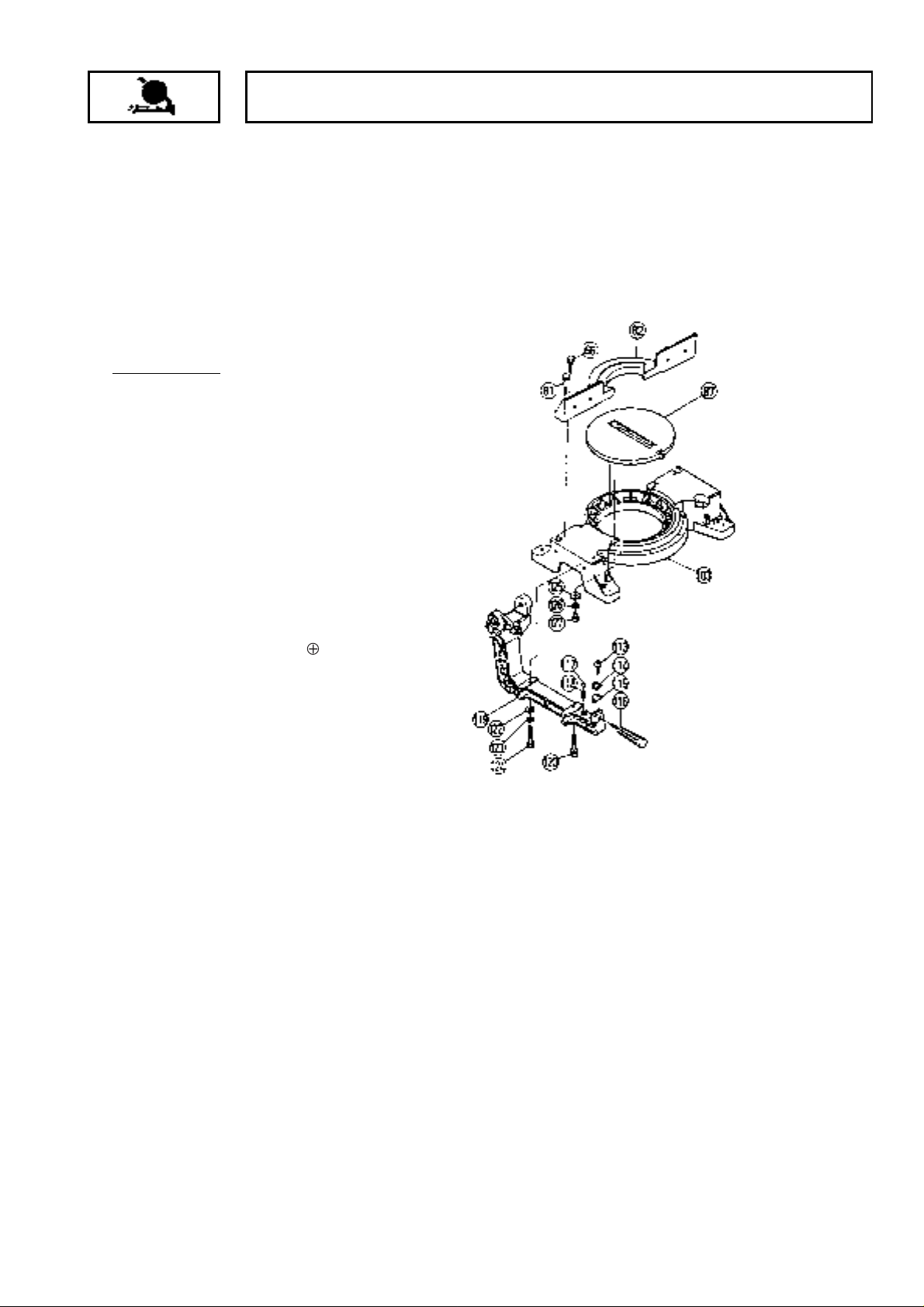
(1) Disassembly of the Base and Turn Table:
Tools Required:
17 mm Box Spanner
•
A. After removing the M10 x 65 Bolt [120] and
M10 x 65 Screw (G) [124] which fix the Hinge
[119], the Hinge [119] and upper portions
(Gear Case, etc.) can be separated from the
main body.
B. Remove the four M10 x 40 Bolts [66] which
fix Vise (B) [82], and separate Vise (B) [82]
from the Base Ass'y [103].
C. Remove the two M6 x 16 -Hd. Machine
Screws [127]. The Turn Table [87] can then
be removed by pushing it up lightly from the
rear portion of the Base Ass'y [103].
[NOTE] When removing the Hinge [119], be
very careful not to lose the D12.7 Steel
Ball [117] and Sprint (C) [118].
--- 1 ---
Page 2
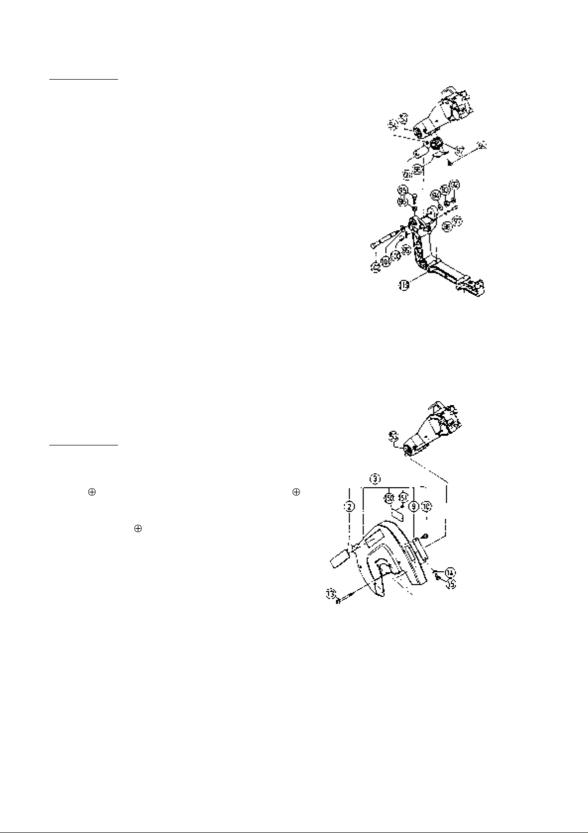
(2) Disassembly of the Spring Section and the Sleeve:
Tools Required:
17 mm Wrench, 10 mm Wrench, 6 mm Hex. Bar Wrench, and
•
Plus Screwdriver
A. This step of disassembly is dangerous and requires close
attention at all times. Particular caution is necessary after
releasing the fixing device (paragraph D.).
B. Push the Gear Case [53] forward and down to its lowered
position, and lock it in that position with the fixing device
(push in the Set Pin [97] to engage the Grip [100]).
C. Loosen the M10 Lock Nut [96], and screw the M10 x 40 Bolt
[95] fully into the Hinge [119].
D. Being very careful as cautioned above, release the fixing
device (Set Pin [97] and Grip [100]) and slowly and carefully
raise the Gear Case [53].
E. Loosen the two M6 x 10 Hexagon Socket Hd. Set Screws
[54], and remove the M12 Lock Nut [92] and M12 Nut [93].
Next, gently pull out the Hinge Shaft [102]. Finally, loosen
the two M4 x 10 Flat Hd. Screws [65], take off the Spring
Cover [68], and take out the Spring [67] and Sleeve [69].
(3) Disassembly of the Saw Cover Section:
Tools Required:
Plus Screwdriver
•
The Saw Cover Ass'y [3] can be disassembled by removing the
M4 x 10 -Hd. Machine Screws [15] and four D5 x 90 -Hd.
Tapping Screws [13] However, please note that to remove two
of the four D5 x 90 -Hd. Tapping Screws [13] it is necessary
to insert the screwdriver through the holes at either end of the
Arrow Mark on the Saw Cover which indicates the rotational
direction of the saw blade.
Insert screwdriver through
Arrow Mark holes for
disassembly and reassembly.
--- 2 ---
Page 3
(4) Disassembly of the Switch and Handle Section:
Tools Required:
Plus Screwdriver
•
A. When only the Switch [22] must be disassem-
bled, first loosen the two M5 x 20 -Hd.
Machine Screws [18] and M5 x 16 -Hd.
Machine Screw [16] which fix the Handle [20].
Then loosen the two M5 x 12 -Hd. Machine
Screws [27] and two D4 x 25 Tapping Screws
[35] which fix the Handle Cover [25]. The
Handle [20] can then be removed from the
Gear Case [53].
B. After loosening the D4 x 10 -Hd. Tapping
Screws [21], the Switch [22] can be separated
from the Handle [20].
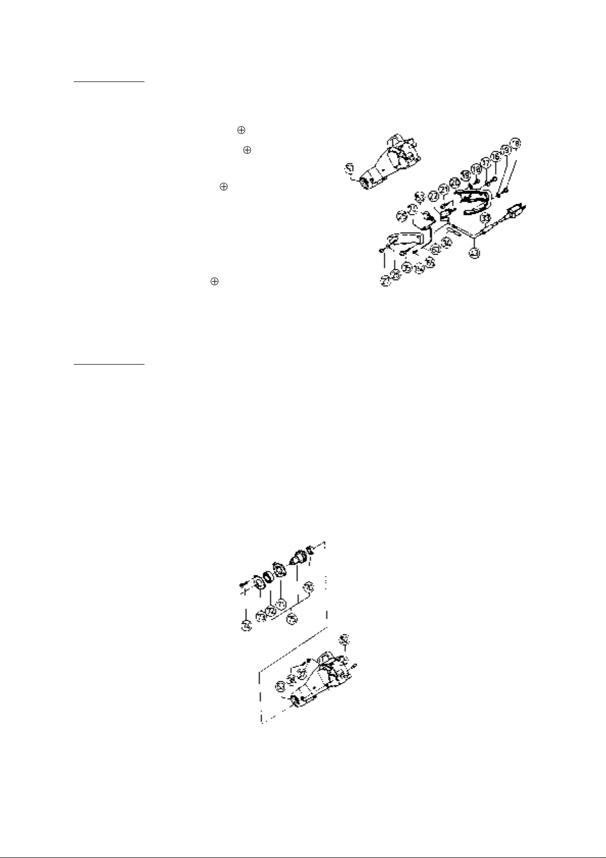
(5) Disassembly of the Spindle Section and stopper Pin:
Tools Required:
Plus Screwdriver, Pliers, Wooden or Plastic Hammer
•
A. Remove the Saw Cover Ass'y [3] by following the disassem-
bly procedures in paragraph (3), above.
B. After extracting the D7 E-Type Retaining Ring [37] from the
Stopper Pin [52], the Stopper Pin [52] and Gauge Spring
[38] can be taken out.
C. After loosening the three M6 x 25 Flat Hd. Screws [74],
gently tap on the saw cover side of the Gear Case [53] to
loosen and remove the Spindle Gear Ass'y [75].
--- 3 ---
Page 4
(6) Disassembly of the Armature Ass'y and Stator Ass'y:
Tools Required:
Plus Screwdriver, Nippers, Wooden or Plastic Hammer
•
1. Disassembly of the Armature Ass'y:
A. Remove the Saw Cover Ass'y [3] and handle Cover [25] by following the disassembly procedures in
paragraphs (3) and (4), above.
B. Remove the two leadwires of the Stator Ass'y [46] from the Switch [22]. As there is another leadwire
connected at the Connector [24], cut off the wires as closely to the Connector as possible.
C. Remove the two Brush Caps [55] from the Housing Ass'y [84], and take out the two Carbon Brushes
[40].
D. Remove the Armature Ass'y [36] from the Housing Ass'y [84].
2. Disassembly of the Stator Ass'y:
A. Loosen the two D4 x 10 -Hd. Tapping Screws [41], and remove the Tail Cover [42] from the Housing
Ass'y [84].
B. Disconnect the two Stator Brush Terminal Ass'ys [158] from the Brush Holders [56].
C. Loosen the two M5 x 75 -Hd. Machine Screws [48] which fix the Stator Ass'y [46]. Then tap gently on
the Gear Case mounting end of the Housing Ass'y [84] to loosen and remove the Stator Ass'y [46].
1-2. Reassembly:
Reassembly can be accomplished by following the disassembly procedures in reverse. However, special
attention should be given to the following items.
(1) If the Armature, Stator, Switch or any other electrical component has been replaced, conduct the following
tests:
--- 4 ---
Page 5

A. With the main switch turned ON, measure the insulation resistance between the plug prongs and exposed
metal portions of the frame with a 500V DC Megohm Tester. The reading should be in excess of 7
megohms.
B. If possible, a dielectric strength test should be conducted. With a Dielectric Withstand Voltage Tester, apply
4,000 volts between the plug prongs and exposed metal portions of the frame for one (1) minute with the
main switch turned ON. Confirm that there is no "flashover" or breakdown of the insulation.
C. After electrical testing has been completed, connect the plug to the power source and confirm the following:
There is no irregular noise.
•
Commutation of the Commutator portion is not excessive.
•
There is no abnormal vibration.
•
(2) Ensure that the thickness of the vinyl tube which covers the leadwires from the Stator is in excess of 1.2 mm,
and ensure that the vinyl tube completely covers the Stator leadwires all the way up to the polycarbonate
portion of the Switch Handle.
(3) If the M12 Nut and M12 Lock Nut on the Hinge Shaft are tightened excessively, it may interfere with the
smooth movement of the Gear Case. If they are not tightened sufficiently, the Gear Case may move and
vibrate on the Hinge, causing uneven cutting of the workpiece. Be very careful to ensure that the M12 Nut and
M12 Lock Nut tightened properly to prevent vibration of the Gear Case, yet allow smooth movement of the
Gear Case.
1-3. Assemblies Requiring Careful Adjustment:
(1) Perpendicularity Adjustment of the Saw Blade (or Dummy Disc) and Vise (B):
If the Hinge is disassembled from and then reassembled to the Turn Table, it is necessary to perform
necessary adjustments to ensure the perpendicularity of the Saw Blade (or Dummy Disc) and Vise (B).
A. Mount the D12.7 Steel Ball [117] and Spring (C) [118] onto the Hinge [119], and temporarily fix the Hinge
onto the Turn Table [87] with the M10 x 65 Bolt [120] and M10 x 65 Screw (G) [124]. At this time, the Table
Insert [86] and Guard [61] should be removed from the Turn Table [87].
B. Perform adjustment as necessary so that the Saw
Blade (or Dummy Disc) is positioned exactly in
the center of the Table Insert mounting groove, as
Table Insert
Mounting Groove
Turn Table
Position Saw Blade
(or Dummy Disc) in
exact center.
illustrated left, and tighten the M10 x 65 Bolt [120]
and M10 x 65 Screw (G) [124]. At this time,
confirm without fail that the D12.7 Steel Ball [117]
is properly engaged in the 0˚ setting hole in the
Base Ass'y [103].
Square
Vise (B)
Saw Blade (or Dummy Disc)
--- 5 ---
C. As illustrated, left, fit a square to the side surface
of the Saw Blade (or Dummy Disc), and adjust
Vise (B) as necessary to ensure it is exactly
perpendicular to the Saw Blade. Then thoroughly
tighten the four M10 x 40 Bolts [66].
Page 6

D. Finnally, ensure that the arrow mark on the Indicator [114] is properly aligned with the 0˚ setting of the Scale
[89], and tighten the two M5 x 10 -Hd. Machine Screws [113].
(2) Cutting Depth Adjustment:
The adjustment procedures and dimensions described below are based on the use of a 380 mm diameter Saw
Blade.
A. Cutting depth adjustment procedures are described in the Instruction Manual. If the M10 x 40 Bolt [95] is
not properly adjusted, the following may occur:
Maximum machine cutting capacity cannot be obtained.
•
The Saw Blade could cut into the Turn Table [87].
•
B. To obtain maximum machine cutting dimensions, set the Turn Table [87] to the 0˚ setting, lower the Saw
Blade, and perform adjustment with the M10 x 40 Bolt [95] so that the appropriate dimension between the
surface of Vise (B) and Point A (where the Saw Blade intersects the surface of the Turn Table) is
obtained, as illustrated below.
Vise (B)
90˚
(0˚ Scale
Setting)
185 mm
Saw Blade
(Point A)
Check this dimension
at 0˚ Scale Setting
185 mm
(Point A)
C. On completion of the above adjustment, lower the Saw Blade and ensure that it does not come in contact
with the Turn Table.
(3) Saw Blade Height Setting Adjustment:
When the Gear Case [53] has been disassembled and then
Saw Blade
reassembled, adjust the M10 x 40 Bolt [95] without fail to
set the Saw Blade at the most appropriate height (H) above
the Turn Table for the operator to conveniently perform
Workpiece
H
normal cutting operations. Details concerning adjustment
procedures are listed in the Instruction Manual; study them
Vise (B)
carefully, and set the height in accordance with cutting
Saw Blade
needs.
1-4. Confirmation of Appropriate Insulation:
When making leadwire connections, do not remove any more of the insulation covering than is absolutely
necessary. For example, ensure there are no exposed wire cores projecting from connectors, terminals, etc. In
particular, carefully confirm that there are no exposed wire cores at the terminals of the Switch. In addition,
carefully avoid pinching leadwires between the Handle and Handle Cover during reassembly.
--- 6 ---
Page 7

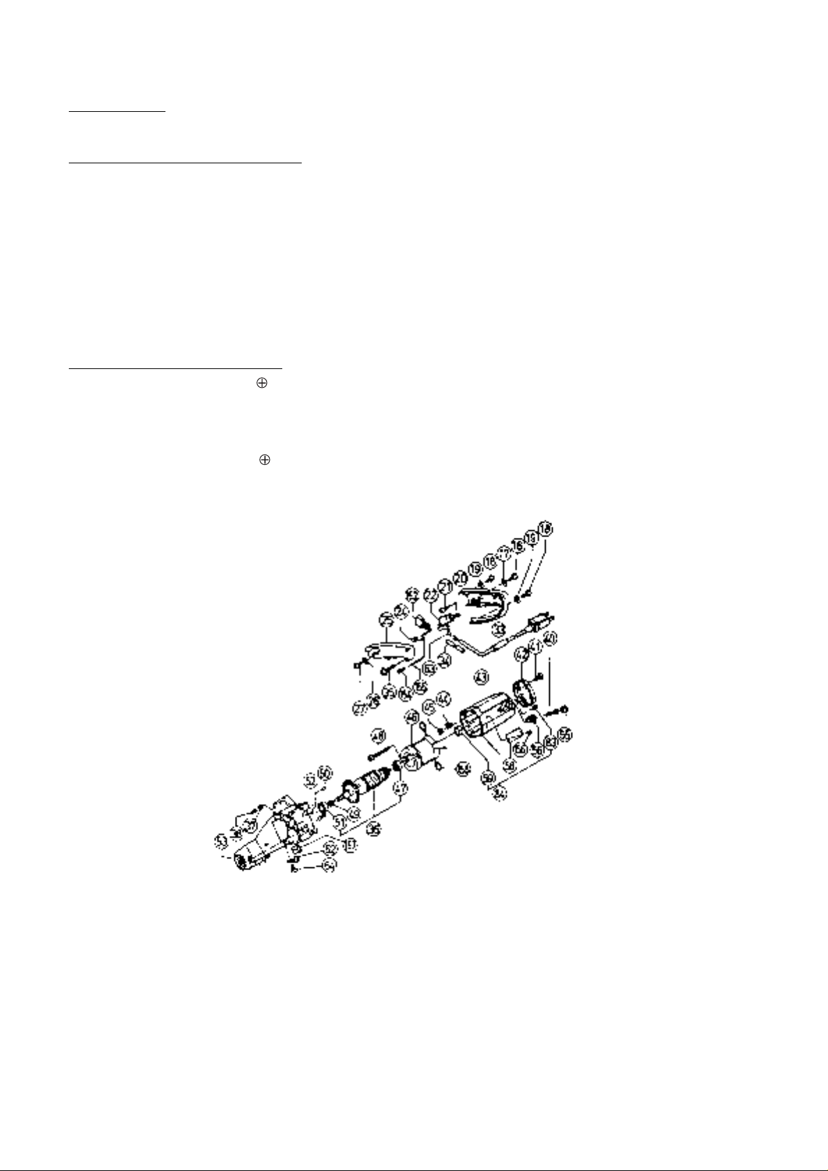
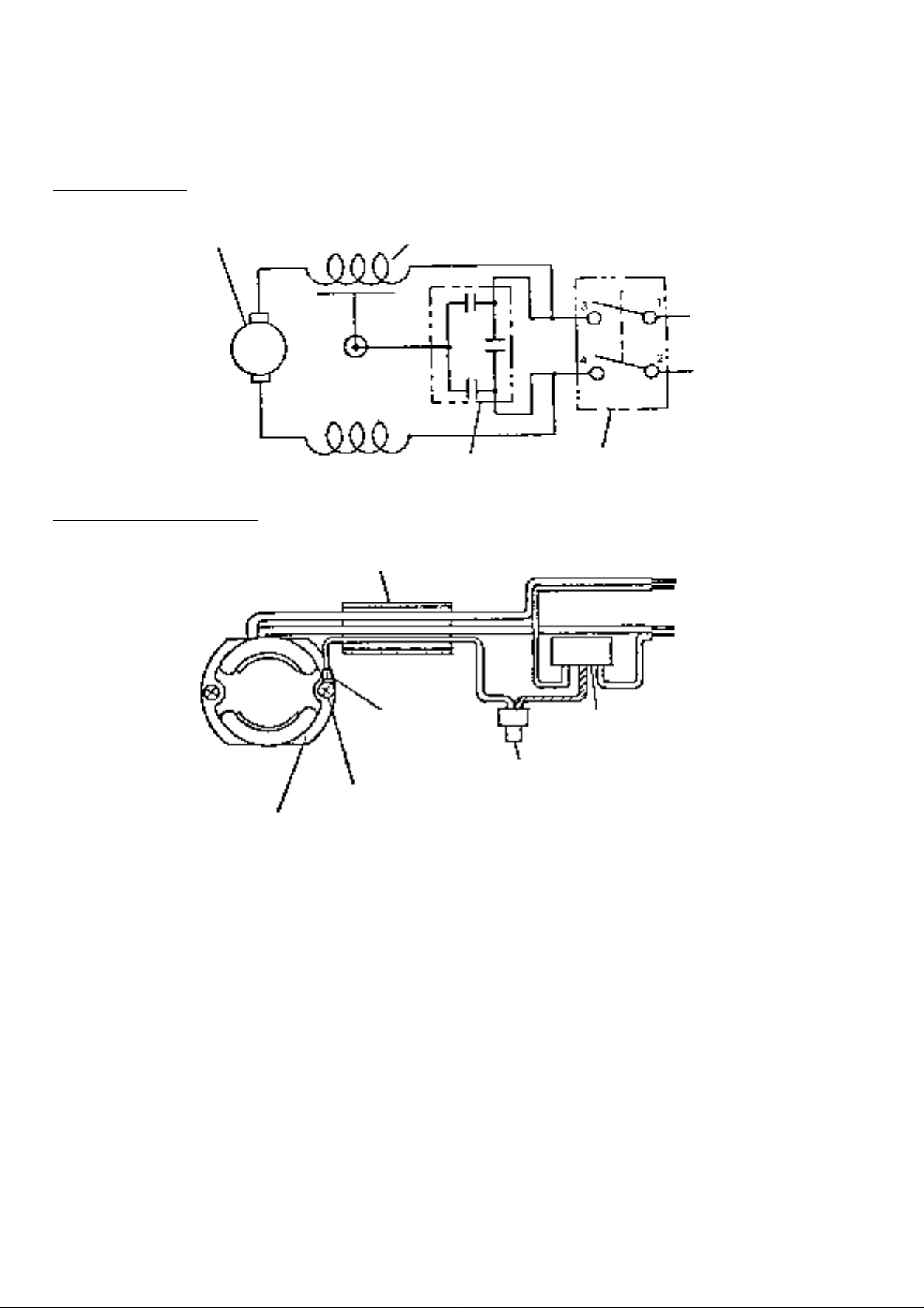
1-5. Wiring Diagrams and Leadwire Arrangements:
Perform wiring work as illustrated below.
(1) For Products with a Dynamic Brake (115V Specification Products for the U.S. and Canada Only):
WIRING DIAGRAM
Armature
Ass'y
LEADWIRE ARRANGEMENT
Stator Ass'y
Brown
Tube (A)
Switch
White
Black
Cord
White
Connector
Noise Suppressor
Connector
Switch
Cord
Cord Armor
--- 7 ---
Page 8
(2) For Products with a Noise Suppressor:
[NOTE] The wiring diagram for products without a Noise Suppressor is the same as that illustrated below with the
exception of the Noise Suppressor section.
WIRING DIAGRAM
Armature
Ass'y
LEADWIRE ARRANGEMENT
Stator Ass'y
Vinyl Tube
Noise Suppressor
Black
Red
Switch
Black
Red
Stator Core
Green
Terminal
(w/o insulation
tube)
M5 x 75 Machine Screw
Noise
Suppressor
Yellow/Green
Connector
--- 8 ---
Page 9

2. TROUBLESHOOTING GUIDE:
The circled numbers in the descriptions below correspond to the item numbers in the Parts List and exploded
assembly diagram.
(All Dimensions in Millimeters)
Item Phenomenon Possible Cause (s) Standard Countermeasure (s)
1.
Inaccurate cutting.
(Unable to obtain accurate
perpendicularity of cut
surface.)
(Mitered joints cannot be
accurately aligned.)
Fig. 1
0.1
80
Fig. 2
0.1
Perpendicularity
Standard:
0.2/90
A. Improper perpendicularity
between Vise (B) [82] and the
Base Ass'y [103] causes
inclined bevel cutting, resulting
in inaccurate angles.
B. Improper perpendicularity
between Saw Blade and Turn
Table [87] causes Saw Blade
to cut into Workpiece at
inclined angle.
C. Excessive deflection of the
Saw Blade.
(Excessive vibration)
D. Turn Table [87] is not
properly fixed with the Side
Handle [116], and moves
during the cutting operation.
Within
0.1/80
(Fig. 2)
0.2/190
(Fig. 1)
0.26/φ 370
(With
Dummy
Disc)
----
Adjust or replace Vise (B) [82].
Adjust M12 Nut [93] and M12
•
Lock Nut [92] to eliminate gap
and vibration between Hinge
[119] and Gear Case [53].
Replace Hinge [119].
•
(If Hinge damaged or deformed)
Replace Gear Case [53].
•
(If Gear Case damaged or deformed)
Replace Turn Table [87].
•
(If Turn Table damaged or deformed)
Replace the Saw Blade.
•
Replace Washer (A) [28] and/or
•
Washer (B) [29].
Securely fix the Turn Table [87]
with the Side Handle [116] and
recheck after next cutting.
Within 0.1
Fig. 3
Within 0.1
Fig. 4
E. Surface of Vise (B) uneven
(worn or damaged) and
causes uneven cutting of the
workpiece.
F. Surface of Turn Table [87]
uneven (worn or damaged)
and causes uneven cutting of
the workpiece.
G. Excessive looseness or excessive tightening of the turn
connection between the Hinge
[119] and Gear Case [53]
which causes either vibration
or irregular movement of the
Saw Blade, and subsequent
uneven cutting.
H. Excessively fast cutting
operation speed causes
deflection of the Saw Blade,
and subsequent uneven
cutting.
Within 0.1
(Fig. 3)
Within 0.1
(Fig. 4)
----
----
Replace Vise (B) [82].
Replace the Turn Table [87].
Check for material (chips, dust,
•
etc.) in the joints of the Hinge
[119], Gear Case [53] and
Hinge Shaft [102], and clean as
necessary.
Readjust M12 Nut [93] and M12
•
Lock Nut [92] to ensure proper
movement of the Gear Case
[53].
Reduce cutting operation
•
speed.
(Appropriate cutting time for a
100 mm (4") workpiece is 10 --15 seconds.
Use a Tungsten Carbide Tipped
•
Saw Blade for wood or aluminum (Code No. 959024).
I. Excessive pressure is
applied because of a dull Saw
Blade.
--- 9 ---
----
Resharpen or replace the Saw
•
Blade.
Page 10

Item Phenomenon Possible Cause (s) Standard Countermeasure (s)
Inaccurate cutting.
(Unable to obtain accurate
perpendicularity of cut
surface.)
(Mitered joints cannot be
accurately aligned.)
2.
Cutting operation results in
rough cutting surfaces
A = 0.02/60
J. The workpiece is not properly secured, and moves during the cutting operation.
K. Curved or rough surface of
the Workpiece causes
workpiece movement during
cutting operation.
A. Excessive deflection of the
Saw Blade.
(Inherent Saw Blade deflection
will cause rough surfaces.)
B. Incorrect selection of Saw
Blade, or dull Saw Blade.
(While a regular TCT Saw
Blade provides faster cutting
speed, it also produces
rougher surfaces than a TCT
Saw Blade for wood or
aluminum.)
C. Improper perpendicularity
between Saw Blade and Turn
Table [87] causes Saw Blade
to cut into workpiece at slightly
inclined angle, and cause
rough cutting surface.
----
----
0.26/φ 370
----
0.2/190
(Fig. 1)
Secure the workpiece with Vise
(A), and check cutting accuracy.
Plane the surface of the workpiece to remove defects, and
recheck the cutting accuracy.
Replace the Saw Blade. (To obtain very fine cutting surfaces,
Hitachi's TCT Saw Blade for
wood or aluminum (Code No.
959024) is recommended.)
Replace the regular TCT Saw
•
Blade with a TCT Saw Blade for
wood or aluminum (code No.
959024).
Resharpen the Saw Blade.
•
Adjust M12 Nut [93] and M12
•
Lock Nut [92] to eliminate gap
and vibration between Hinge
[119] and Gear Case [53].
Replace Hinge [119]
•
(If damaged or deformed).
Replace Gear Case [53]
•
(If damaged or deformed).
Replace Turn Table [87]
•
(If damaged or deformed).
Fig. 5
Fig. 6: Left Bevel Cutting
Fig. 7: Right Bevel Cutting
D. Washers (A) and (B) not
parallel because of surface
defects or other damage.
E. Improper perpendicularity
between Vise (B) and the
Base Ass'y [103] causes
improper support of the
workpiece.
F. Surface of Vise (B) uneven
and causes improper support
of the workpiece.
G. Excessively fast cutting
operation speed.
H. When the Saw Blade cuts
against the natural grain of the
wood workpiece, inferior
cutting surfaces are obtained.
0.02/60
(Fig. 5)
Within
0.1/80
(Fig. 2)
Within 0.1
(Fig. 3)
----
----
Remove surface defects from or
replace Washer (A) [28] and/or
Washer (B ) [29].
Adjust or replace Vise (B) [82].
Replace Vise (B) [82].
Reduce cutting operation speed.
(Appropriate cutting time for a
100 mm (4") workpiece is 10 --- 15
seconds.)
Cut with the natural grain of the
wood workpiece.
Fig. 6
Fig. 7
Workpiece
--- 10 ---
Workpiece
... With Grain (Smooth cutting
surface)
... Against Grain (Cutting surface
inferior to with grain.
Page 11

Item Phenomenon Possible Cause (s) Standard Countermeasure (s)
Cutting operation results in
rough cutting surfaces.
I. The workpiece is not securely fixed in position.
J. The Turn Table is not securely fixed in position with the
Side Handle [116].
K. Excessive looseness or excessive tightening of the turn
connection between the Hinge
[119] and Gear Case [53].
L. Curved or rough surface of
the workpiece causes
workpiece movement during
cutting operation.
M. Excessive vibration during
cutting operation.
----
----
----
----
----
Securely fix the workpiece with
Vise (A) [79].
When performing cutting operations, securely tighten the Side
Handle [116] without fail to fix the
Turn Table in position. (The Ball
Index Settings at 0˚, 15˚, 22.5˚,
30˚ and 45˚ are affected by
vibration, and are not sufficient to
securely fix the Turn Table.)
Repair or adjust affected parts as
described in Item 1. G, above.
Plane the surface of the workpiece to remove defects, and
recheck the cutting.
Check each of Possible Causes
A, B, D, J and K, above.
--- 11 ---
 Loading...