


HA13609ANT
Three-Phase Brushless Motor Driver
ADE-207-232 (Z)
1st. Edition
May 1997
Description
The HA13609ANT is a 3-phase brushless motor driver IC with digital speed control. It is designed for use
as a PPC or LBP scanner motor driver and provides the functions and features listed below.
Function
• Power MOS and power bipolar transistor driver circuits
• 16-bit serial interface
• Variable-speed digital speed control circuit
• Digital PLL
• Digital ready circuit
• PWM oscillator circuit
• Charge pump circuit
• Integrating amplifier circuit
• Current limit circuit
• Overshoot prevention circuit
• Braking function (with braking compete signal)
• Forward/reverse direction circuit
• Hall open circuit protection
• Watchdog timer (LVI, POR, and RST outputs)
• Stuck rotor protection
Features
• High breakdown voltage (50V/30mA) power transistor drive circuit
• PWM drive
• Variable speed control is possible (varying the servo filter constants is not required)
• Selectable rotation control method (discriminator control, PLL plus discriminator control)
• Selectable feedback type (voltage or current)
• Allows both PWM frequency switching and 100% duty operation
• Selectable current limiting level
• Braking mode selection (reverse braking, regeneration braking)
HA13609ANT
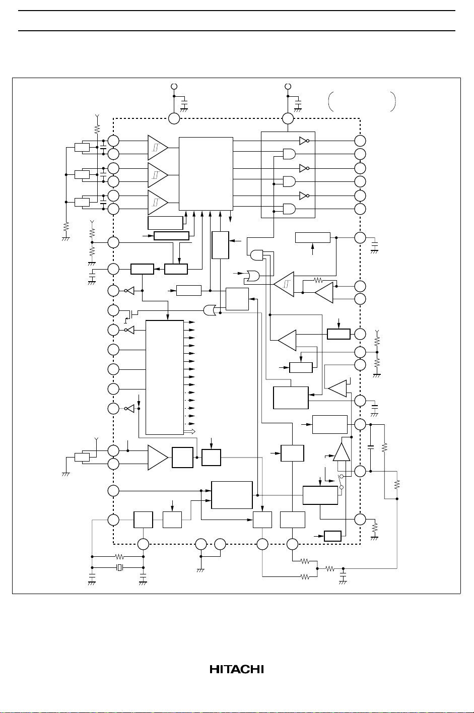
Block Diagram
V
SS
R101
Hu
Hv
Hw
V
SS
R102
R126
R127
C108
RST
Monitor output
(Ready: Low)
DATA OUT
CLK
f
= 8 MHz
MAX
ENABLE
DATA
Rotation monitor output
V
SS
MR
SPEED CLK
(0.2 to 5 kHz)
20 p 20 p
42
41
40
39
38
37
20
22
8
7
4
1
2
3
6
29
28
5
9
1 M
8 MHz
MAX
U+
U–
V+
V–
W+
W–
FH × 3
1.4 V
Hall amplifier
+
–
+
–
+
–
Open circuit
protection
R/F
RWD/FWD
P.O.R L.V.I
BRAKE
Serial port
(16 bits)
+
AMP
–
OSC D2
10
21
Wave-
shaping
D2
V
SS
1.25 V
BRAKE
form
(5 V)
C101
Matrix
FH × 3
Overshoot
OSI
preven-
tion
Duty 100
No/8
Counter
MOTOR ON
BRAKE (2 bit)
DUTY 100
READY
O.S.I ON
(2 bit)
V
Ref
MASK
CONTROL
RWD/FWD
D1 (2 bit)
D2 (2 bit)
PLL SEL OR Icp, PC ON
VP (3 bit)
f
(2 bit)
PWM
MODE SEL
D1
D1
Programmable
discriminator
(1024 to 4095)
11 30
Ready
PLL
13
25
PWM
comp.
Current
sense
V
Ref
Stuck rotor
protector
Ready
±4, ±8%
Discrimi-
V
–
+
–
+
V
nator
14
PS
C102
PWM OSC
f
PWM
40 k
Ref
PC
Precharge
Integral
CONT.
Icp × 2
Charge
pump
R4
R5
V
= Bip use
SS
10 to 50 V= MOS use
U
36
U
35
V
34
V
33
W
32
W
31
12
Error
amp
–
27
+
17
MASK
26
MASK
24
18
1.1 V
–
+
Buffer
23
16
–+
15
19
VpVp
R6
C4
(Open collector)
(Push-pull)
C106
Current feedback input
Error amplifier input
V
SS
R106
R107
C105
C3
R3
R7
R1
2

HA13609ANT
Pin Functions
Pin No. Pin Name Function
1 CLK Serial port reference signal input
2 ENABLE Serial port data write/latch signal input
3 DATA Serial port data input
4 DATA OUT Serial port data transfer complete signal output
5 SPEED CLK Speed command signal input
6 TACHO OUT Rotation monitor (MR, Hall ×3) output
7 READY Ready and braking done (no/8) output (open collector output)
8 RST Power supply (VSS) monitor output. High when a reduced power-supply
voltage is detected.
9 OSC IN Oscillator circuit input. Reference signal for all circuits other than the
serial port.
10 OSC OUT Oscillator circuit output
11 S-GND Small-signal ground
12 PWM OSC Connection for the capacitor that sets the oscillator frequency.
13 PLL OUT SPEED CLK vs. speed detection signal speed comparison output
14 DIS OUT SPEED CLK vs. speed detection signal phase comparison output
15 INTEG IN Integrating amplifier input
16 CP OUT Charge pump and integrating amplifier output
17 ERROR AMP IN Error amplifier input
18 BUFFER OUT Buffer amplifier output. Connect to pin 17 when current feedback is
selected.
19 R1 Charge pump output current and PWM oscillator frequency setting
20 LVI Reduced voltage detection level setting
21 V
SS
22 POR Power-on reset delay time setting
23 LOCK PRO Motor rotation constraint mode coil current on/off time setting
24 V
25 V
Ref
PS
26 C Sense Motor coil current detection
27 C F B Current feedback input
28 MR IN – Speed detection input
29 MR IN + Speed detection input
30 P-GND Output driver ground
Small-signal circuit power supply. 5.5V maximum
Current limit setting
Output driver power supply. 50V maximum
3

HA13609ANT
Pin Functions (cont)
Pin No. Pin Name Function
31, 33, 35 U, V, W Lower arm driver push-pull output. Driven by a PWM signal. (Connect
power NMOS or NPN transistors.)
32, 34, 36 U, V, W Upper arm driver open drain output. (Connect a power PMOS or PNP
transistor.)
37 to 42 U+, U–
V+, V–
W+, W–
Hall signal inputs
4
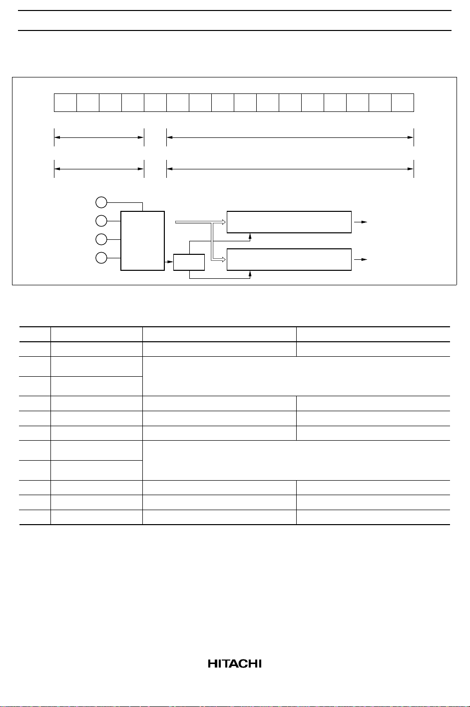
Serial Port Input Data Structure
HA13609ANT
MSB
A4
A3 A2 A1 A0 D10 D9 D8 D7 D6 D5 D4 D3 D2 D1 D0
Dummy Mode control
Dummy Data control
A0 = 1
A0 = 0
DATA OUT
DATA
CLK
Serial
port
(16 bits)
ENABLE
Mode Control Register (A0 = 1)
Bit
MD0
MD1
MD2
MD3
MD4
MD5
MD6
MD7
MD8
MD9
MD10
Symbol
MOTOR ON
BRAKE 1
BRAKE 2
DUTY 100
READY
O.S.I ON
V
Ref 1
V
Ref 2
MASK
CONTROL
R/F
Decoder
A0
MOTOR ON
MD1
MD2
BRAKE
DUTY 100%
4%
Active
MD6
MD7
V
Ref
×2
Discriminator
Reverse
Mode control register (11 bits)
A0 = 1
Data control register (11 bits)
A0 = 0
1
1
0
OFF
0
0
V
Ref
×2
Brake
←
×1
0
0
1
Brake
1
1
0
Brake
2
0
1
←
×0.75
MOTOR OFF
1
1
3
DUTY
8%
Non Active
1
1
←
×0.5
×1
Discriminator + PLL
Forward
LSB
Mode control
Data control
0
*10
*2
*3
5

HA13609ANT
Data Select Register (A0 = 0)
Bit
DD0
DD1
DD2
DD3
DD4
DD5
DD6
DD7
DD8
DD9
DD10
Symbol
D1 A
D1 B
D2 A
D2 B
PLLSEL1 OR Icp
PLLSEL2 OR PC ON
VP1
VP2
VP3
f
PWM1
f
PWM2
DD0
DD1
D1
DD2
DD3
D2
DD4
DD5
PLL OUT(Vp-p)
×100%
DD6
DD7
DD8
VP (V)
DD9
DD10
f
PWM
1/1
1/1
2.2
f
PWM
×1
1
0
0
0
0
0
0
0
0
0
0
Notes: 1. Off: The brake function does not operate.
Brake 1: Braking up to No/8.
Brake 2: Braking up to No/8, and then regenerative braking.
Brake 3: Regenerative braking. The No/8 signal is output.
During a braking operation, when the MR frequency when braking completes cannot be detected
in the circuit (During braking, the speed detection signal for under setting is not output over the
2/D1 occurrence. Thus this occurs more easily for lower settings.), reverse rotation may continue
in some cases. Note that this bit is also used to set the rotation monitor output (FH × 3 or the MR
frequency). FH × 3 is only output from the rotation monitor when motor on (MD0 = 1) and brake 3
are selected.
2. The ready setting range has the following manufacturing variation:
4.3% ±25% (@MD4 = 1)
8.6% ±25% (@MD4 = 0)
3. This function masks the current limiter input (pin 27) (incorrect operation due to the recovery
current). See page 20 for details.
4. The PLL output setting indicates a change relative to 3.5 Vp-p. See the electrical characteristics.
This is valid when MD9 = 0 (PLL control). Note that DD4 also functions as the Icp selection in
discriminator control mode.
V
Icp =
DD4 = 1 . . . . . Icp × 2
DD4 = 0 . . . . . Icp × 1
R1
4 · R1
@MD9 = 1
1
0
1/2
1
0
1/2
1
0
←
×75%
1
0
0
+0.15
1
0
←
×1.4
0
1
1/4
0
1
1/4
0
1
←
×50%
0
1
0
+0.3
0
1
←
×1.9
1
1
1/8
1
1
1/8
1
1
←
×25%
0
0
1
+0.45
1
1
←
×2.8
1
1
0
+0.6
1
0
1
–0.15
0
*4
1
0
1
1
–0.3
*5
1
1
–0.45
*60
6
HA13609ANT
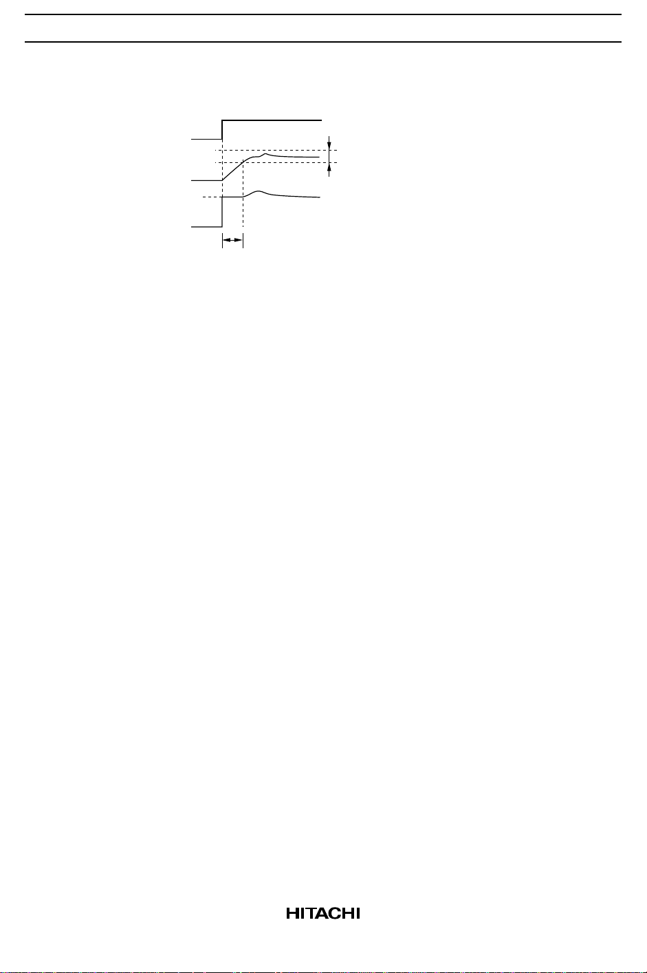
DD5 also controls the PC on function to reduce motor rotation overshoot when MD9 is 1
(discriminator control). This function does not operate when D9 is 0. The precharge voltage (i.e.,
the integrator output voltage initial clamp voltage) can be set by Vp1 to Vp3 (DD6 to DD8). The
figure shows the precharge operation.
MD0 or MD10
Ready lock range
NO
Integrator output Vp
0 V
Precharge
5. The Vp setting indicates the change relative to 2.2V. See the electrical characteristics.
6. Indicates the change relative to f
. See the setting formula.
PWM
(MD4)
7
HA13609ANT
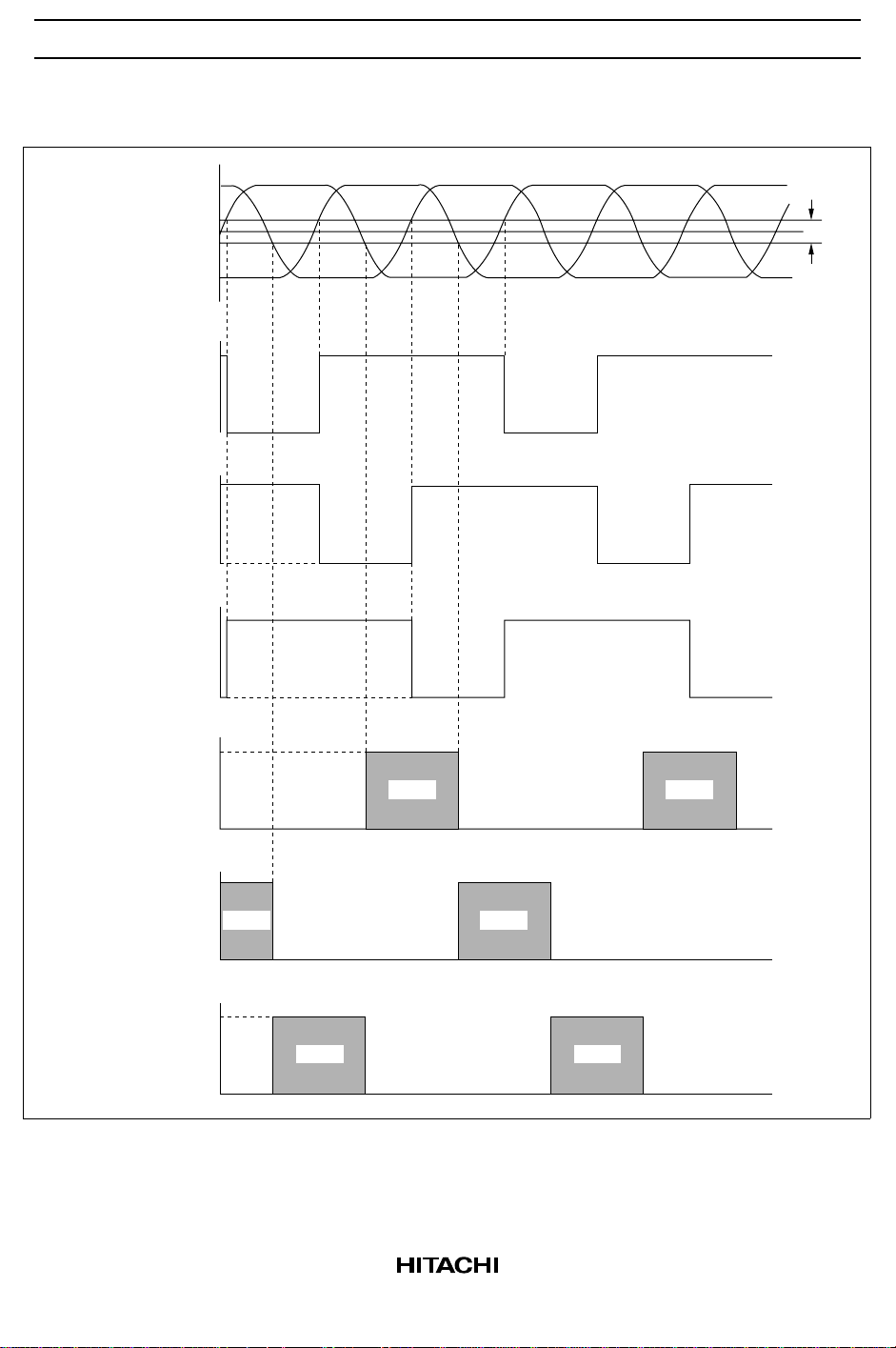
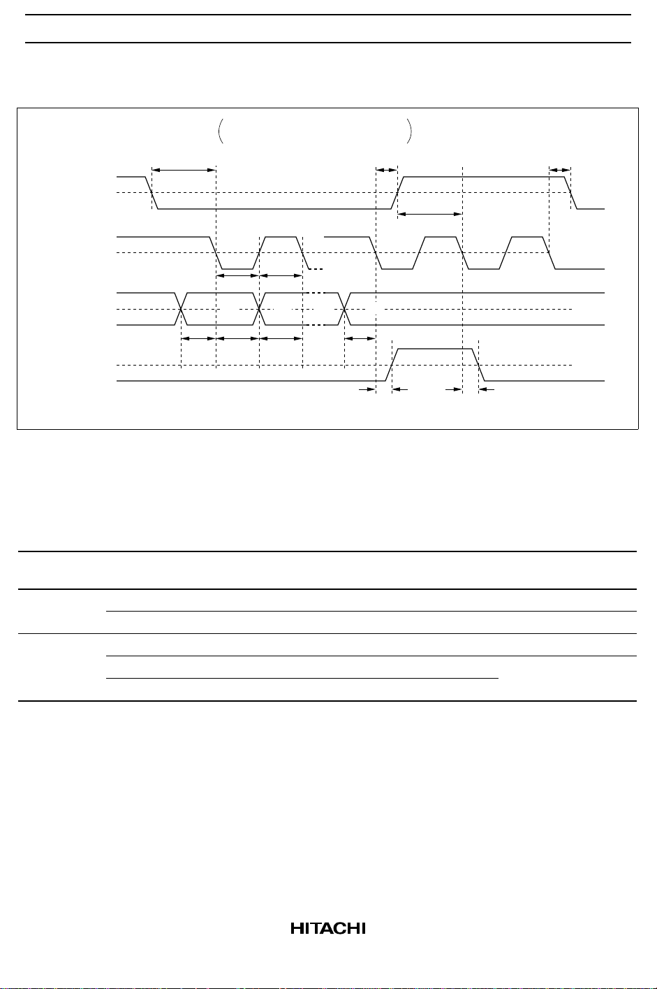
Timing Chart (Forward Mode)
Hall amplifier input
V
U output
V
V output
V
W output
OH1
V
OH1
V
OH1
V
OL
OL
OL
+
Hu Hv Hw
0
Vhys
–
U output
V output
W output
V
OH
PWM PWM
V
OL
V
OH
PWM
V
OL
V
OH
PWM
V
OL
PWM
PWM
8
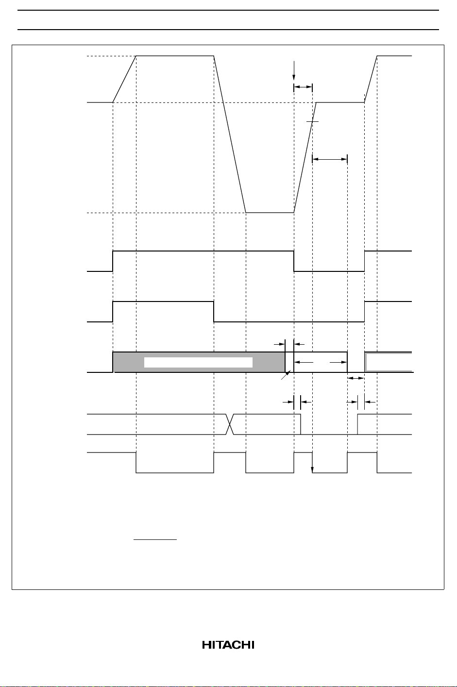
Serial Port Timing Chart
HA13609ANT
ENABLE
CLK
DATA
DATA OUT
Braking Function
Input and Output Logic
tr, tf < 20 nsec, tsu, th > 20 nsec
tw > 40 nsec
tsu
tw tw
A4 A3 D1 D0
tsu th tsu tsu
The tr and tf times are stipulated
at 10% and 90%, respectively.
th
th
50%
tsu
50%
50%
50%
td1 td2
≤ 50 nsec ≤ 50 nsec
Serial Port Input Output
MOTOR ON
(MD0)
1 * * 0 Forward OFF *1
0 0 0 * — OFF *2
Notes: 1. OFF: The braking function does not operate.
2. The IC goes to standby mode.
3. See the description of mode control for details on the braking operation.
BRAKE 1
(MD1)
* * 1 Reverse OFF
* * 0 Reverse Brake *3
* * 1 Forward
BRAKE 2
(MD2)
R/F
(DD10) Rotation Direction Braking
9
HA13609ANT
(
N1
Forward
Reverse
N2
MDO
(MOTOR ON)
MD10 (R/F)
MD1 (BRAKE1)
to
MD2 (BRAKE2)
SPEED
CLK input
Braking set
Braking or
regeneration
0
*3
tset up
Rotation monitor output set
Braking set
N2N1 N1
braking
Regeneration
braking
*2
*3
thold
Rotation monitor
output set
*1
*3
tset up
Monitor output
(open drain)
Notes: 1.
10
*4
ReadyReady Ready
The IC goes to standby mode when MOTOR ON, BRAKE1, and BRAKE2 are all 0.
2.
Hold the data values here.
3.
thold, tset up >
4.
The No/8 (braking completion) function does not operate when BRAKE1 and BRAKE2 are 0.
Note that the No/8 detection signal is initialized to the high level in the mode in note 1
standby mode).
1
f
SPEED CLK
× 4
No/8
detection

HA13609ANT
Basic Application Circuit (Bipolar Transistor Circuit, Discriminator + PLL, Voltage
Feedback, and Hall Elements)
MPU
R102
C103
X’tal
C104
R101
Hu
Hv
Hw
MR
V
V
SS
SS
R126
R127
C108
V
SS
R105
21
V
U+
42
U–
41
V+
40
V–
39
W+
38
W–
37
LVI
20
22
P.O.R
RST
8
7
Monitor output
DATA OUT
4
1 CLK
ENABLE
2
DATA
3
SPEED CLK
5
29
MR IN+
MR IN–
28
Rotation monitor
6
output
OSC IN
9
OSC OUT
10
11 30
V
SS
V
PS
C101
25
V
SS
PS
36
U
35
U
R108
R109
R114
Q1
Q2
D1
D2
R117
R115
R110
34
V
R111
33
V
Q3
Q4
D3
D4
R118
R116
R112
32
W
R113
31
W
Q5
Q6
D5
D6
R119
R120
V
input
output
26
C107
C106
12
24
Ref
C105
23
R
NF
V
SS
R106
R107
27
17
18
16
C3
R3
15
19
R7
R1
Current limiter
PWMOSC
Lock protection
Current feedback
Error amplifier input
Buffer amplifier
Integrator output
Integrator input
Discrimi-
PLL
nator
13 14
R4
R6
C4
R5
11

HA13609ANT
Application Circuits
Application Circuit 1 (Discriminator)
Error amplifier input
Buffer amplifier output
Integrator output
Integrator input
Discrimi-
natorPLL
13 14
Application Circuit 2 (MOS Transistor Circuit)
V
SS
C101
21
V
SS
C102
25
V
PS
U
U
V
V
W
W
17
18
16
C3
M1
M2
M3
M4
M5
M6
R2
R1
NF
C1
V
PS
D1
D2
D3
D4
D5
D6
15
19
ZD1
R114
R108
36
R109
35
R117
ZD2
R115
R110
34
R111
33
R118
ZD3
R116
R112
32
R113
31
R119
R
12
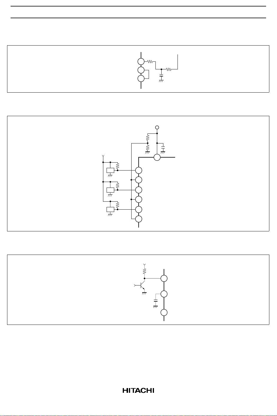
Application Circuit 3 (Current Feedback)
Current feedback input
Error amplifier input
Buffer amplifier output
Application Circuit 4 (Hall IC input)
V
SS
HA13609ANT
R
R125
27
17
18
V
SS
R103
R104
21
V
R122
IC
IC
IC
R123
R124
42
41
40
39
38
37
SS
U+
U–
V+
V–
W+
W–
NF
R121
C110
C101
Application Circuit 5 (External Reset Input)
External reset input
H: standby
V
SS
C108
R126
LVI
20
22
P.O.R
RST
8
13

HA13609ANT
External Components
Recommended
Part No.
R101, R102 — Hall element bias current 12
R103, R104 — Hall IC applications, Hall input voltage 14
R105 1MΩ Oscillator stabilization
R106, R107 — Current limiter reference voltage 15
R108 to R113 — Power transistor base current limiter 16
R114 to R119 — Power transistor base-emitter resistors (gate-source resistors) 16
R120 ≥ 4.7kΩ Current limiter filter 13
R121 — Current feedback input filter 9
R122 to R124 — Hall IC output current 14
R125 — Current feedback input gain adjustment 10
R126, R127 — LVI operating voltage, external reset input pull up 11
R
NF
R1 ≥ 1.5kΩ Integration constant, PWM carrier frequency 2, 3, 5
R2 — Integration constant 2
R3 to R7 — Integration constant 3
C101, C102 ≥ 0.1µF Power supply stabilization
C103, C104 10p to 50pF Oscillator stabilization 7
C105 — Lock protection operation time 4
C106 — PWM carrier frequency 5
C107 — Current limiter filter 13
C108 — Power-on reset delay time 11
C110 — Current feedback input filter 9
C111 to C113 — Hall output stabilization 8
C1 — Integration constant 2
C2 — Integration constant 2
C3, C4 — Integrator filter 3
ZD1 to ZD3 ≈ 20V MOS power transistor gate destruction protection 8
D1 to D6 — Fly wheel diodes 8
X’tal 4 to 8MHz Oscillator 6, 7
Notes: 1. Current limiter operates according to the following formula:
Value Purpose Note
— Current detection 1
V
Ref
Iop =
Here, V
[A]
R
NF
is the value according to the V
Ref
select function.
Ref
14

HA13609ANT
2. Use the following formulas as a guideline for setting the integration constant (@MD9 = 1). To
minimize rotation deviation, set R1 to a relatively small value.
2π
ωo ≤
R1
However, R1 must be in the range 1.5kΩ ≤ R1 ≤ 15kΩ.
20
9.55 · V
=
4 · J · ωo · No
· fMR · D1
· KT · R2
R1
· A
[rad/s]
[Ω]
C1 = 1 / (√10 · ωo · R2)
C2 = 10 · C1
Here, No : Rotation speed [min
f
: MR frequency [Hz]
MR
[F]
[F]
–1
]
D1 : Divider determined by D1 select
V
: Charge pump bias voltage 1.16 [V]
R1
K
: Motor torque constant [N·m/A]
T
J : Motor moment of inertia [kg·m
2
]
A : PWM comparator current gain [A/V]
Voltage feedback method: A =
Current feedback method: A =
V
: Power system power-supply voltage [V]
PS
V
: Motor back EMF [V
E
2Vps – 0.83V
R
G
B
NF
Rm · Vosc
– Vsat
E
P-P
/T·T]
Vsat : External transistor saturation voltage [V] (See the electrical characteristics)
Rm : Motor coil resistance [Ω/T·T]
Vosc : PWM amplitude voltage [V
G
: Buffer amplifier gain [V/V] (See the electrical characteristics)
B
] (See the electrical characteristics)
P-P
3. Use the following formulas as guidelines for setting the integrator filter:
First determine the angular frequency of ω
= 2π · fMR · D1 [rad/s]
ω
P
Determine the angular frequency of ω
9.55
1
No
·
J
≈
ω
M
KT ·
Vref
R
NF
– T
L
[rad/s]
for DIS OUT and PLL OUT.
P
for Motor.
M
Determine the ωo.
ωo = √ω
Determine the integrator’s DC gain G
(E)
· ωM [rad/s]
P
J · ωo
=
9.55 · KT · A
(E)
·G
Z
· D1 · 2π · Kø · PLL SEL
60
1
ωo
.
Here, Kø : PLL gain = 0.28 [V/rad/s]
T
: Rated load torque [N·m]
L
PLL SEL : PLL output ratio
Vref : Current limiter reference voltage [V]
Z : MR pulse per round [P/R]
15

HA13609ANT
Set C3 and derive the integration constants from following formulas.
R6 = 0 Ω
R3 =
ωP · C3
R3
R5 =
G
(E)
C4 =
2 · R5 · ωo
R7 = R5
Next, determine R4 to match the phase of PLL OUT.
R4
=
(V
Here, V
When log ω
required. Use the following formula to set the phase advance;
C5 · R8 >
DIS
PLL
4. The following formulas determine the stuck rotor protect detection time t
limiter operating time), the output off time t
operating waveforms.
t
t
t
See the electrical characteristics for the definitions of ∆V1, ∆V2, Isink, Isource, and Is.
(MD0k to 2 = Low)
LP
OFF
set
=
=
∆V1
Isink
=
Isource
V
P
1
1
(3.46 – V
– 1.2) – (1.9 – VP) · R3 / R5
P
P
) R3
: See the electrical characteristics.
is greater than 2, a phase advance to compensate for this phenomenon is
P/ωM
20 · 2
ω
P
R4
R6 R7
R8
R5
C4
C5
· C105 ≈ 0.09 × 10⁶ · C105
∆V2
· C105 ≈ 0.32 × 10⁶ · C105
LH2
· C105 ≈ 0.0005 × 10⁶ · C105
Is
Standby
Enable
, and the setup time t
OFF
[sec]
[sec]
[sec]
(detects the current
LP
. The figures show the
set
Current limiter
operation
16
I
RNF
0
V
Lock
protect
pin
LH1
V
LH2
V
LL
0
t
set
t
LP
t
OFF
Output off
t
LP
∆V1
∆V2
Note that a capacitor with a leakage current sufficiently smaller that Isource must be used for
C105.

HA13609ANT
5. The PWM carrier frequency f
f
PWM
= 0.0489
1
C106 · R1
6. The relationships between the crystal oscillator frequency f
f
, the speed detection signal fMR, and the discriminator resolution (number of counts) C are
CLK
is determined by the following formula:
PWM
[Hz]
OSC
and the speed command clock
shown below.
= fMR·D1
f
CLK
f
= f
OSC
·1 / D2·C [Hz]
CLK
However, C must be in the range 1024 ≤ C ≤ 4095
Here, D1 : The MR signal divisor determined by D1 select
D2 : The crystal oscillator frequency divisor determined by D2 select.
Configuration of the speed control and phase control blocks when @MD9 = 0
Buffer amplifier
f
Speed signal
f
MR
SPEED CLK
f
CLK
D1
MR’
–+
CLK counter
Discriminator
counter setting
16
C3
R3
X’tal
f
OSC
D2
Discriminator
(1024 to 4095)
Charge
pump
15
R7
19
R1
4Icp
PLL
Discrimi-
nator
Vp
Discriminator
PLL SEL
4% pulse
output
14
PLL output
R4
R6
C4
13
R5
Note: If possible, Tr and Tf for the SPEED CLK signal should be under 20 ns when using this circuit.
17

HA13609ANT
g
Timing in phase control mode
f
MR'
≈ 3.6 V
Discriminator output
≈ 0 V
A A
ACC ACC
A × 4% A × 4%
ACCACC
PLL output
≈ 3.6 V
≈ 1.85 V
≈ 0 V
ACCACC
∆Vo
Integrator output
Configuration of the speed control block when @MD9 = 1
f
Speed signal
f
MR
SPEED CLK
f
CLK
D1
MR’
CLK counter
Discriminator
counter setting
X’tal
f
OSC
D2
Discriminator
(1024 to 4095)
Charge
pump
DEC DEC
Buffer
amplifier
16
C2
R2
R1
19
R1
4Icp
C1
Note: If possible, Tr and Tf for the SPEED CLK si
18
nal should be under 20 ns when using this circuit.

HA13609ANT
7. The table below lists reference values for the stabilization capacitors C103 and C104 for the
crystal oscillator element according to the frequency used.
X’tal (MHz) C103, C104 (pF)
4 to 6 ≈ 20 to 40
6 to 8 ≈ 10 to 20
Use a resonance resistance of under 50Ω as a criterion for selecting the crystal element used.
8. Include these components if required.
9. The cutoff frequency of the filter formed by C110 and R121 should be between 3 and 10 times
the PWM oscillator frequency.
10.The gain, G
= 1 +
G
CTL
11.The formulas below determine the relationship between capacitor C108, which sets the power on
reset (POR) delay time, and the resistors R126 and R127, which set LVI.
V
= V
LVI
However, V
V
= R126 · I
HYS
However, V
t
= 0.052 × 10⁶ · C108 [sec]
POR
The time t
longer.
, from the error amplifier input to RNF is given be the following formula:
CTL
Rif
R125
SD
V
R127
> 3V
LVI
HYS
– V
LVI
POR
LVI
> 2.5V
HYS
is the time required for the oscillator to reach stability. This time should be 20ms or
V
HYS
R126
1 +
[V]
[V]
VSD, I
: See the electrical characteristics.
HYS
V
SS
< 2.0 V
0 V
2.0 V
0 V
0 V
1.3 V
t
POR
t
POR
POR
RST
When using an external reset input to set the IC to the standby state, pin 20 must be set to a low
level that is under 0.4V.
12. When the Hall inputs are common mode input, the open circuit protection circuit makes the
output transistors non-operational. When all the Hall input phases are open, the lower side
output transistors become non-operational.
The output transistors will be disabled if one or two phases are disconnected (become open) only
when the Hall inputs are common mode.
19

HA13609ANT
13.When setting up the current limiter filter consisting of R120 and C107, R120 should be 4.7k Ω or
larger, and C107 and R120 should function as a filter for the recovery current. This filter masks
the recovery current due to internal circuits for the current limiter input (pin 26) and the C107
discharge operation determines the PWM off time (by making the current limiter input a low
impedance). See the figures.
Output (U to W)
V
RNF
1/f
PWM
ON ON
C107 discharge
t
MASK
t
MASK
Current limiter input
voltage (pin 26)
≈ 0 V
For recovery current masking:
t
MASK
48
= [SEC]
fosc
64
to
fosc
@MD8 = 1
t
MASK
24
= [SEC]
fosc
32
to
fosc
@MD8 = 0
14. Use the formula below as a guideline for determining the values of R103, R104, and R122 to
R124 when a Hall IC is used.
R103 // R104 = R122 to R124 < 20kΩ
15.Take the current limiter input current (see the electrical characteristics) into consideration when
determining the values for R106 and R107.
16.Determine the values of R108 to R119 based on the characteristics of the output power
transistors used and the output driver characteristics (see the electrical characteristics).
17. Design the wiring in applications so that the potential of the pin 11 ground (the small-signal
ground) does not become higher than that of the pin 30 ground (the output stage ground) as
shown in the figure.
V
SS
11 30
20

HA13609ANT
Absolute Maximum Ratings
Item Symbol Rated Value Unit Note
Power-supply voltage V
Input voltage V
SS
V
PS
IN
Output voltage Vout 50 V 4
Output current Iout 30 mA 5
Allowable power dissipation P
T
Operating temperature Topr –20 to 70 °C
Storage temperature Tstg –55 to +125 °C
Notes: 1. A surge voltage of 6.0V is allowed for up to 10ms. Note that the operating range is as follows:
V
= 4.25 to 5.5V
SS
2. The maximum is VSS if bipolar transistors are used as the output transistors.
The maximum is 50 V if bipolar transistors are used as the output transistors.
3. Applies to the logic input pins 1, 2, 3, 5, and 9, and to the analog input pins 17, 20, 24, 26 to 29,
and 37 to 42.
4. Applies to the output pins 32, 34, and 36, and to pin 7, the monitor output pin.
5. Applies to the output pins 31 to 36. The maximum value for the monitor output pin is 10mA.
5.5 V 1
VSS to 50 V 2
V
SS
V3
0.8 W
21

HA13609ANT
O
O
O
Electrical Characteristics
Item Symbol Min Typ Max Unit
Current drain I
Logic
inputs
Input lowlevel current
Input high-
I
I
I
I
I
SSO
SS
PSO
PS
IL
IH
— 3.0 6.5 mA MD0 to 2 = 0,
— 15 25 mA MD0 to 2 = 1,
— 0.13 0.5 mA MD0 to 2 = 0,
— 2.5 3.5 mA MD0 to 2 = 1,
— –50 –100 µA 1 to 3, 5, 9
—0 ±10 µA
level current
Input low-
V
IL
— — 1.5 V
level voltage
Input high-
V
IH
3.5 — — V
level voltage
Clock
f
CLK
4 — 20 MHz 9
frequency
Logic
outputs
Output highlevel voltage
Output low-
V
OH1
V
OL1
3.5 4.6 — V IOH = 0.5mA 4, 6, 8, 10
— 0.25 0.4 V IOL= 0.5mA
level voltage
Hall
amplifier
Input
resistance
Common-
Rh — 10 ±25% kΩ 37 to 42
Vh 1.5 — VSS–1.5 V
mode input
voltage range
Differential-
Vd 70 — VSS/2 mV
mode input
voltage range
Output
drivers
Hysteresis V
Output high-
level voltage
HYS
V
OH2
V
OH2
V
OH2
— 40 — mV Rh = 400Ω 1, 2
VPS–1.8 VPS–1.6 — V I
10 12.5 15 V I
5.5 9.0 — V I
Test
Condition
VSS = 5.5V
VSS = 5.5V
VPS = 50V
no load,
VPS = 50V
= 20mA,
H
VPS = V
SS
= 1mA,
H
VPS = 24V
= 1mA,
H
VPS = 12V
Applicable
Pins Notes
21 6
25 6
31, 33, 35
22

Electrical Characteristics (cont)
SS
HA13609ANT
Item Symbol Min Typ Max Unit
Output
drivers
Output leakage
current
Output low-
I
LEAK
V
OL2
——±100 µAV
— 0.15 0.3 V IOL = 20mA 31 to 36
level voltage
Output
T
PHI
— — 1.0 µsIO = 10mA 3
response time
PWM
oscillator
Oscillator lowlevel voltage
T
PLH
V
L
— — 1.0 µs
— 1.1 ±10% V 12
and
PWM
com-
Oscillator highlevel voltage
V
H
— 2.8 ±10% V
parator
Oscillator
f
PWM
2 — 30 kHz 2
frequency
range
Oscillator
ferr1 — 7.7 ±10% kHz f
frequency
precision
Comparator
V
PHYS
— 50 — mV 2
hysteresis
Current
Input current I
IN1
——±10 µA Vi = 0 to 2V 24, 26
limiter
Speed
detection
amplifier
Offset voltage V
Common-mode
input voltage
range
Differential-
OFF
V
CM
V
DIFF
–15 –25 –40 mV Vi = 0.5 to 2V 26
1.5 — V
V 28, 29
–1.5
60 — V
SS
mV
mode input
voltage range
Gain Gain — 32 — dB f = 1kHz 2
Input current I
Input current
IN2
I
28
I
29
Iratio 1.45 — 2.25 — I28 / I
——±20 µA Vi = 1.4V
–146 –95 –62 µA Vi = 0V
–67 –53 –39 µA Vi = 0V
ratio
Input sensitivity V
S
15——mV 6 2
P-P
Test
Condition
= 50V 32, 34, 36
OH1
× 1,
PWM
R1 = 6.2kΩ,
C106 =
1000pF
29
Applicable
Pins Notes
23

HA13609ANT
Electrical Characteristics (cont)
Item Symbol Min Typ Max Unit
Clock
oscillator
Oscillator
frequency range
Oscillator
fosc 4 — — MHz X’tal 9, 10
ferr2 — — ±0.01 % X’tal = 8MHz 2
frequency
precision
Program
Count range N 1024 — 4095 Count 14, 16
-mable
discrimi-
nator
Operating
frequency
fdis — — 20 MHz 4
Count error DC 0 — 1LSB —
Charge
R1 voltage V
R1
— 1.16 ±10% V R1 = 1.5kΩ 19
pump
Charge current I
Discharge
I
CP+
CP–
— 190 ±10% µA R1 = 1.5kΩ,16
— 190 ±10% µA Vo = 2.0V
current
Current ratio I
CP+/ICP–
0.8 1.0 1.2 —
Leakage current Ioff1 — — ±100 nA Vi = 1.5V
Clamp voltage Vclamp 2.8 3.0 — V
Digital
ready
Lock range
manufacturing
∆N——±25 % 7
variation
Precharge
Buffer
amplifier
Clamp
voltage (1)
Internal
reference
Vcp(1) — Vp ±10% V 16
Vref — 1.15 ±10% V 16
voltage
Output
Ro 9.8 14 18.2 kΩ 18
resistance
Maximum output
V
B(MAX)
— 0.7 ±10% V
voltage
Error
Voltage gain G
Input current I
B
IN3
–8 –6 –4 dB
——±150 nA Vi = 1.5V 17, 27
amplifier
Offset voltage Voff — –25 –50 mV
Voltage gain Ge — 60 — dB Vi = 2.5V 2
Gain-bandwidth
Be — 0.1 — MHz 2
product
Feedback
Rif — 40 ±25% kΩ VSS = 5V
resistance
Test
Condition
Applicable
Pins Notes
24

Electrical Characteristics (cont)
HA13609ANT
Item Symbol Min Typ Max Unit
Integrating
amplifier
Internal
reference
voltage
Internal
Vp — 2.2 ±10% V DD6 to 8 = 0 15, 16
∆Vp — 2.2+∆Vp ±10% V
reference
voltage
difference
Input current I
Output voltage V
Voltage gain G
Gain-
IN4
OH3
V
OL3
I
B
I
—— ±250 nA Vi = 1.5V
2.75 3.0 — V Io = 0.5mA
— — 0.9 V Io = 0.5mA
— 60 — dB Vi = 2.5V 2
— 0.3 — MHz 2
bandwidth
product
PLL and
offset
discriminator
Output highlevel voltage
Output lowlevel voltage
V
OH4
V
OL4
— 3.6 ±10% V Io = 0.1mA 13, 14
— 0.1 0.2 V
output
Monitor
output
Output leakage
current
Output low-
I
LEAK2
V
OL5
—— 50µAVOH = 50V 7
— 0.2 0.4 V IOL = 10mA
level voltage
Stuck
rotor
Minimum
detection time
t
LP
—40 ±25% ms C105 = 0.47µF23 2
protector
Output off time t
High-level V
voltage V
Low-level
OFF
LH1
LH2
V
LL
— 165 ±25% ms
3.0 3.2 — V
2.5 2.7 — V
— 1.4 1.6 V
voltage
Potential ∆V1 — 1.9 ±10% V V
difference ∆V2 — 1.35 ±10% V V
Detection-time
I
SINK
—25 ±30% µA Pin 23 voltage
sink current
Output off
I
Source
— 5.0 ±30% µA Pin 23 voltage
source current
Standby-mode
I
S
— 4.7 ±35% mA Pin 23 voltage
source current
Test
Condition
LH1–VLL
LH2–VLL
= 2.5V
= 2.5V
= V
LH
Applicable
Pins Notes
2
25

HA13609ANT
Electrical Characteristics (cont)
Item Symbol Min Typ Max Unit
LVI Internal reference
voltage
Hysteresis
current
Output voltage
maintained range
P.O.R Delay time t
Vsd 1.13 1.21 1.29 V Turn on 20
I
V
HYS
LV
POR
—50±25% µA
2.0 — — V 21
— 24.5 ±25% ms C108 = 0.47µF 8, 22
Notes: 1. Timing chart
2. Design target values. These are not tested at delivery time.
3. The figure below stipulates the output response time. This is not tested at delivery time.
90%
10%
T
PLH
T
PHL
4. Stipulated at the discriminator input frequency.
5. See the timing charts.
6. Stipulated at conditions in which the OSC input is fixed.
Test
Condition
Applicable
Pins Notes
26

Reference Data
Current Drain vs. Supply Voltage Current Drain vs. Supply Voltage
30
Tj = 25°C
HA13609ANT
4
Tj = 25°C
(mA)
20
SSO
, I
SS
10
Current Drain I
0
1.5 4.5
0
2.5 3.5 5.5
Supply Voltage V
Output Driver Low-Level Voltage vs.
Output Current
0.4
(V)
OL
0.3
SS
(V)
I
SS
I
SSO
Tj = 125°C
3
(mA)
PSO
, I
PS
2
1
Current Drain I
0
0
20 30 50
Supply Voltage V
Output Driver High-Level Voltage vs.
Output Current
15
(V)
OH
10
Tj = 125°C Tj = 25°C
V
= 50 V
PS
PS
(V)
I
PS
I
PSO
4010
Tj = –20°C
0.2
0.1
Output Driver Low-Level Voltage V
0
0
10 20 30
Output Current I
O
(mA)
Tj = 25°C
Tj = –20°C
5
Output Driver High-Level Voltage V
0
0
Output Current I
Tj = 125°C Tj = 25°C
V
= 50 V
PS
10 20 30
(mA)
O
Tj = –20°C
27

HA13609ANT
PWM Frequency vs.
Junction Temperature
10.0
9.0
(kHz)
PWM
C106 = 1000 pF
R1 = 6.2 kΩ
× 1
f
PWM
8.0
7.0
PWM Frequency f
–20 40 70 125
10 100
Junction Temperature Tj (°C)
Error Amplifier Rif vs.
Junction Temperature
70
R1 Voltage vs.
Junction Temperature
1.4
1.3
(V)
R1
1.2
R1 Voltage V
1.1
–20 40 70 12510 100
Junction Temperature Tj (°C)
Integrator vs.
Junction Temperature
2.4
R1 = 6.2 kΩ
(V)
60
50
40
Error Amplifier Rif (kΩ)
30
P
2.3
2.2
2.1
2.0
Integrator Reference Voltage V
–20 40 70 12510 100–20 40 70 12510 100
Junction Temperature Tj (°C)
Junction Temperature Tj (°C)
28

HA13609ANT
Monitor Output vs.
Output Current
0.4
0.3
(V)
OL
Tj = 125°C
0.2
Tj = 25°C
0.1
Monitor Output V
0
0 46 1028
Tj = –20°C
Output Current IO (mA)
LVI Reference Voltage vs.
Junction Temperature
1.4
Lock Protector vs.
Junction Temperature
300
(ms)
200
OFF
, t
LP
t
OFF
100
Lock Protector t
t
LP
0
–20 40 70 12510 100
Junction Temperature Tj (°C)
POR Delay Time vs.
Junction Temperature
30
C105 = 0.47 µ
C108 = 0.47 µ
(V)
1.3
SD
1.2
1.1
LVI Reference Voltage V
Junction Temperature Tj (°C)
25
(ms)
POR
20
15
POR Delay Time t
–20 40 70 12510 100–20 40 70 12510 100
Junction Temperature Tj (°C)
29

HA13609ANT
Package Dimensions
42
1
37.34
38.0 Max
0.89
1.27 Max
1.0
Unit: mm
22
13.4
14.6 Max
21
15.24
5.10 Max
+ 0.10
0.25
0.48 ± 0.101.78 ± 0.25
0.51 Min
1° – 13°
2.54 Min
– 0.05
Hitachi Code
JEDEC Code
EIAJ Code
Weight
DP-42SA
—
SC-551-42
4.42 g
30

Cautions
1. Hitachi neither warrants nor grants licenses of any rights of Hitachi’s or any third party’s patent,
copyright, trademark, or other intellectual property rights for information contained in this document.
Hitachi bears no responsibility for problems that may arise with third party’s rights, including
intellectual property rights, in connection with use of the information contained in this document.
2. Products and product specifications may be subject to change without notice. Confirm that you have
received the latest product standards or specifications before final design, purchase or use.
3. Hitachi makes every attempt to ensure that its products are of high quality and reliability. However,
contact Hitachi’s sales office before using the product in an application that demands especially high
quality and reliability or where its failure or malfunction may directly threaten human life or cause risk
of bodily injury, such as aerospace, aeronautics, nuclear power, combustion control, transportation,
traffic, safety equipment or medical equipment for life support.
4. Design your application so that the product is used within the ranges guaranteed by Hitachi particularly
for maximum rating, operating supply voltage range, heat radiation characteristics, installation
conditions and other characteristics. Hitachi bears no responsibility for failure or damage when used
beyond the guaranteed ranges. Even within the guaranteed ranges, consider normally foreseeable
failure rates or failure modes in semiconductor devices and employ systemic measures such as failsafes, so that the equipment incorporating Hitachi product does not cause bodily injury, fire or other
consequential damage due to operation of the Hitachi product.
5. This product is not designed to be radiation resistant.
6. No one is permitted to reproduce or duplicate, in any form, the whole or part of this document without
written approval from Hitachi.
7. Contact Hitachi’s sales office for any questions regarding this document or Hitachi semiconductor
products.
Hitachi, Ltd.
Semiconductor & Integrated Circuits.
Nippon Bldg., 2-6-2, Ohte-machi, Chiyoda-ku, Tokyo 100-0004, Japan
Tel: Tokyo (03) 3270-2111 Fax: (03) 3270-5109
URL NorthAmerica : http:semiconductor.hitachi.com/
For further information write to:
Hitachi Semiconductor
(America) Inc.
179 East Tasman Drive,
San Jose,CA 95134
Tel: <1> (408) 433-1990
Fax: <1>(408) 433-0223
Europe : http://www.hitachi-eu.com/hel/ecg
Asia (Singapore) : http://www.has.hitachi.com.sg/grp3/sicd/index.htm
Asia (Taiwan) : http://www.hitachi.com.tw/E/Product/SICD_Frame.htm
Asia (HongKong) : http://www.hitachi.com.hk/eng/bo/grp3/index.htm
Japan : http://www.hitachi.co.jp/Sicd/indx.htm
Hitachi Europe GmbH
Electronic components Group
Dornacher Stra§e 3
D-85622 Feldkirchen, Munich
Germany
Tel: <49> (89) 9 9180-0
Fax: <49> (89) 9 29 30 00
Hitachi Europe Ltd.
Electronic Components Group.
Whitebrook Park
Lower Cookham Road
Maidenhead
Berkshire SL6 8YA, United Kingdom
Tel: <44> (1628) 585000
Fax: <44> (1628) 778322
Hitachi Asia Pte. Ltd.
16 Collyer Quay #20-00
Hitachi Tower
Singapore 049318
Tel: 535-2100
Fax: 535-1533
Hitachi Asia Ltd.
Taipei Branch Office
3F, Hung Kuo Building. No.167,
Tun-Hwa North Road, Taipei (105)
Tel: <886> (2) 2718-3666
Fax: <886> (2) 2718-8180
Copyright ' Hitachi, Ltd., 1999. All rights reserved. Printed in Japan.
Hitachi Asia (Hong Kong) Ltd.
Group III (Electronic Components)
7/F., North Tower, World Finance Centre,
Harbour City, Canton Road, Tsim Sha Tsui,
Kowloon, Hong Kong
Tel: <852> (2) 735 9218
Fax: <852> (2) 730 0281
Telex: 40815 HITEC HX
 Loading...