

HIT 2SC4680 Datasheet
2SC4680
Silicon NPN Epitaxial
Application
VHF / UHF high frequency switching
Features
• Low Ron and high performance for RF switch.
• Capable of high density mounting.
Outline
MPAK
3
1
2
1. Emitter
2. Base
3. Collector
2SC4680
Absolute Maximum Ratings (Ta = 25°C)
Item Symbol Ratings Unit
Collector to base voltage V
Collector to emitter voltage V
Emitter to base voltage V
Collector current I
Collector power dissipation P
CBO
CEO
EBO
C
C
Junction temperature Tj 150 °C
Storage temperature Tstg –55 to +150 °C
Electrical Characteristics (Ta = 25°C)
Item Symbol Min Typ Max Unit Test conditions
Collector to base breakdown
V
(BR)CBO
voltage
Collector cutoff current I
Emitter cutoff current I
Collector to emitter saturation
I
V
CBO
CEO
EBO
CE(sat)
voltage
DC current transfer ratio h
FE
Collector output capacitance Cob — 1.0 1.5 pF VCB = 5 V, IE = 0, f = 1 MHz
Note: Marking is “XU–”.
12——V I
——10µAVCB = 12 V, IE = 0
——1 mAV
——10µAVEB = 3 V, IC = 0
— 70 100 mV IC = 20 mA, IB = 4 mA
100 250 — VCE = 5 V, IC = 5 mA
12 V
8V
3V
50 mA
150 mW
= 10 µA, IE = 0
C
= 8 V, RBE = ∞
CE
2
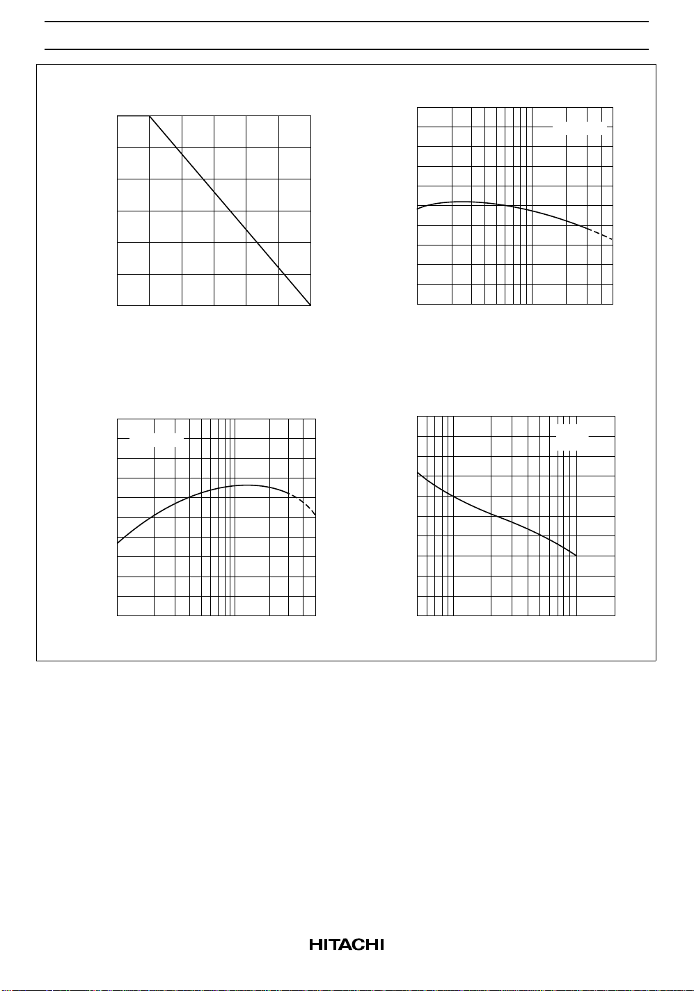
Maximum Collector Dissipation Curve
150
(mW)
C
2SC4680
DC Current Transfer Ratio vs.
Collector Current
500
FE
400
VCE = 5 V
100
50
Collector Power Dissipation P
0
Ambient Temperature Ta (°C)
Gain Bandwidth Product vs.
Collector Current
2.0
VCE = 5 V
1.6
(MHz)
T
1.2
0.8
0.4
300
200
100
DC Current Transfer Ratio h
0
15010050
Collector Current I
(mA)
C
502010521
Collector Output Capacitance vs.
Collector to Base Voltage
1.6
(pF)
ob
1.4
IE = 0
f = 1 MHz
1.2
1.0
0.8
Gain Bandwidth Product f
0
Collector Current I
(mA)
C
Collector Output Capacitance C
502010521
0.6
Collector to Base Voltage V
CB
2010521.00.5
(V)
3
 Loading...