

Page 1
SiteMaster Building CE/Pocket PC
Quick Start Guide for Hilti PD38
1 . Before You Begin….
Recommendation: Before using SiteMaster software,
read and understand the manual of your PDA,
especially about using stylus and Bluetooth. Also read the
manual of your laser meter, especially on using Bluetooth.
Switch On
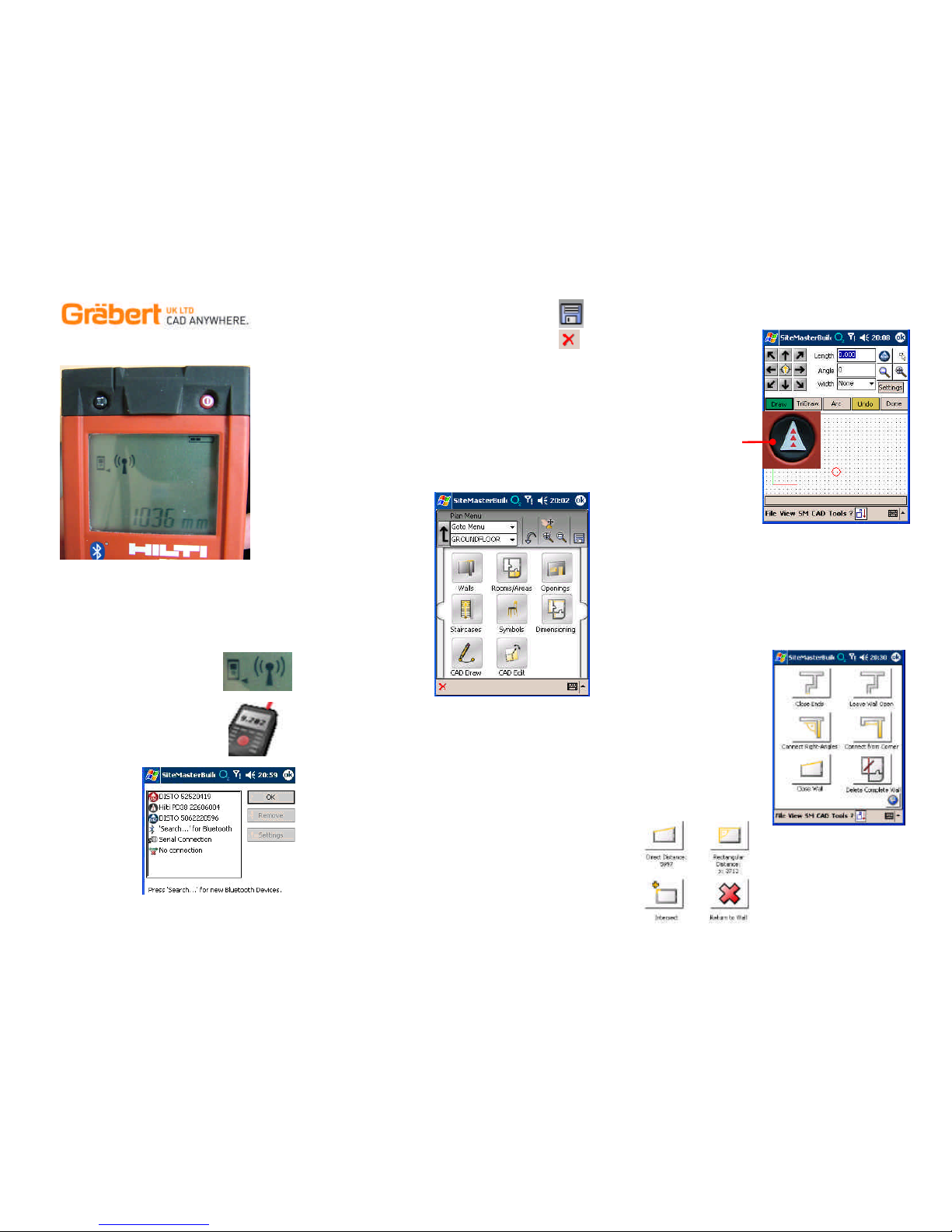
1. Laser meter by pressing the ON/OFF or
DIST button
- By default, on the Hilti the Bluetooth is always
on. The Bluetooth Symbol ‘a keyhole’ will show,
(once connected it has brackets around it)
2. Windows CE/Pocket PC
- Switch on device
- Switch the Bluetooth ON, on the device
- Start SiteMaster Building by double clicking
the icon on the Desktop:
The Bluetooth connection wizard
assists you in setting up a
connection to the Hilti.
Select
- Search… for Bluetooth
to find Bluetooth devices.
Found devices will be listed
- Select device from list,
- then ‘Connect’
- Laser meter confi rms with
beep and brackets appear
around the Bluetooth
symbol
- Click ‘OK’
SiteMaster starts with Icon Menu »Plan Menu«
- Continue e.g. with Walls > Wall
Switch Off
1. SiteMaster Building…..
- Save the drawing..use FILE > SAVE or the save icon
- Close Icon Menu (if open) to do this click the red cross
- File > Exit, Bluetooth connection is closed automatically
- Switch off PDA (If required)
2. Laser distance meter:
- (Bluetooth symbol brackets disappear from display)
- Switch off laser device (press ON/OFF button)
File Formats
SiteMaster Building saves and opens these CAD file formats:
• FLX: SiteMaster drawing
• DWG: AutoCAD
• DXF: DXF format
• DWF: Design-Web-Format (export only)
Use File > Save As to save in these formats
Use File > Open > and set the file type to open them
SiteMaster starts
with the ‘Plan
Menu’….
First things
first…’where do I
start’…
Do the survey how you
want the finished
drawing to look.
i.e. Start with the
Entrance at the bottom
of the screen…draw
the horizontal wall that
the entrance is in, then
draw the rest of the
walls in the room. Then
draw the doors, this
gets you into the next
rooms.
For simplicity, have a go with the 90 degree method to get started.
Select Walls > Wall and pick somewhere on screen…note that
a red circle appears….this is where you are drawing from, and is
typical for the rest of the software.
TRY Drawing just a rectangular room to get started…measure
2 sides and the select the DONE > CLOSE WALL > RECT DIST
Then jump to the ‘Add room area data’.
Sitemaster only has 2 ways to draw…90 degree and Triangulation.
Master these and you can draw anything
Main principle of Sitemaster is to draw the wall structure of a room,
place the area calculation, add in detail…pillars, recesses, doors
windows and then symbols.
(area’s and symbols not available in LT version)
Getting from room to room is done using the door command…as
you place a door you are given the option to draw the walls on
either side of the doorway in the next room. Once drawn, simply
connect onto the ends of these walls to begin and complete the
next room. If not drawn, connect to the sides of the door lines.
Workin
g in 90 degree mode
with a
Hilti
(when in the Wall command)
Whenever you see the
dialogue box above, you
are working in ‘90 degree
mode’
With the Hilti, as soon as
you have taken a
measurement it will appear
in the Sitemaster dialogue
box.
1. Take a
measurement
with the larger
‘DIST’ button
2. Press an arrow
button (ON THE
SCREEN… to
indicate which
direction you
want to draw…
UP, DOWN, LEFT, RIGHT or TO THE 45 DEGREE
ANGLES.
3. Repeat above for other walls in a room
NOTE You can also manually type in measurements and then click
a direction arrow on screen.
The ‘Width’ drop down allows you to specify a wall thickness
(picking or typing). Sitemaster will then draw 2 parallel lines for
each wall.
TRY Drawing just a rectangular room to get started…measure
2 sides and the select the DONE > CLOSE WALL > RECT DIST
Note: The direction selected will be relative to how the drawing is
on the screen. UP will draw
UP the screen, LEFT will draw
towards the left of the screen
etc.
Once you have drawn a full
room perimeter you will have
to exit the ‘Add Wall’ menu…..
To finish off ANY walls you
MUST ALWAYS click the
‘DONE’ button in the ‘Add
Wall’ dialogue and then select
one of the ‘Wall Exit Options’
The ‘Close wall’ option will
give further methods to close
a room off. Use the ‘Direct distance’
to close to where you started from.
‘Intersect’ to close and corner.
‘Rectangular’ if you have drawn 2
sides of a rect shape room already.
I often use ‘Leave Wall Open’ so I
can measure any closing error using
the ‘Inspection’ …’Pick Dist’.
Use’ EDIT > Trim Corner’ to
manually close.
Page 2
Navigate to the Room
Module…
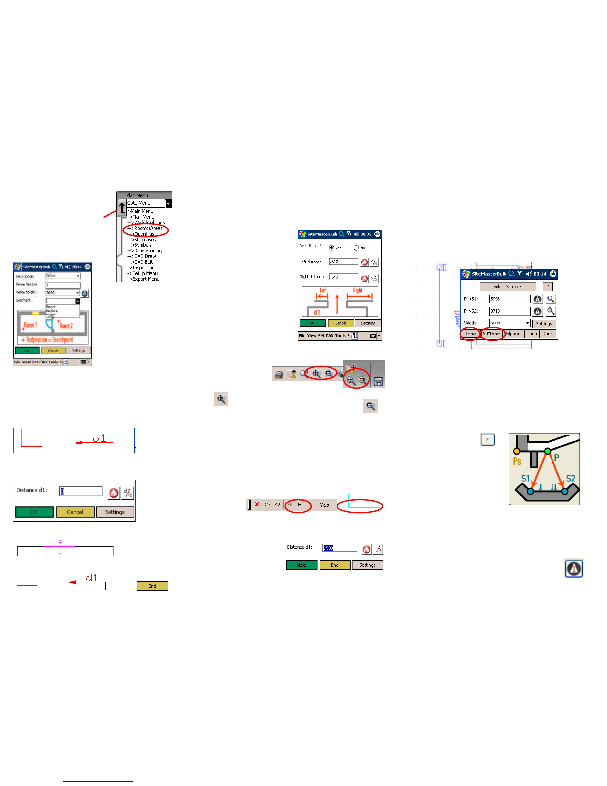
To move between Menus use either
the UP arrow…
Or the ‘Goto Menu’ drop down…
Select ‘Rooms/Areas’
Add Room Area data…
Plan Menu > Rooms/Area’s
icon…then select the ‘Assign New’
1. Fill in the dialogue box…
NOTE The comment drop down
has ‘Edit’ ..you can add your
names
2. then click OK. (dialogue off)
NOTE The height is used to
calculate the volume of the room.
3.Then Click inside the Room
where you want the room area
text to appear…
4. Move, rotate, scale Show/Hide
refers to the text you are
placing..(you can type factors at the command prompt …for a
scale, press the ‘scale’ button and enter 0.7 for instance and the
text will appear 0.7 smaller).
Add detail to the room….
Lets add a chimney breast or pillar into a wall….In the Plan Menu
> Walls menu select the Recess/Chim. command…
Then select the wall where you want to place the object and also at
the end that you want to measure from. A red arrow with d1
appears…this is to indicate where you need to measure from.
Measure to the nearest point of the object…(press any of the
arrow keys on the A6 to ‘send’ this dimension the ’Distance’
Dialogue). Initially you will see a 0, when you send the dimension
it will change
Fill in the Recess/Chim. Dialogue box…width and depth…and click
OK…a pink arrow appears…
Simply pick on screen on the side of the wall line where you want
the object to appear. (in this case where the L is)
The object
appears..click END.
Add a door is just the same with a couple of
differences…..
In the Plan Menu > Openings select the Door command…
Then select the wall where you want to place the door (select at
the end of the wall that you want to measure from)….
A BIG red arrow with d1
appears…this is to indicate
where you need to measure
from. Measure to the nearest
point of the door opening….
Fill in the Door dialogue box
and click OK…
This time when the pink line
appears you need to pick
where the opposite skin of the
wall is. (i.e. outside the room)
Then the ‘Room connection’
dialogue appears.
Measure the wall to the left of
the door (in the next room) and
then the wall to the right, and
click OK.
WATCH OUT…the last thing SiteMaster wants you to do is select
the wall line where the door hinges.
This is where the
ZOOM icons will
come in handy, as
you need to be able to pick the correct wall line
Zoom Extents (has the cross in the middle) and
Zoom window (has a box in the middle) icons.
Zoom Extents when picked will show the whole drawing
Zoom window when picked, needs 2 further points to be picked on
screen….these points will be the 2 diametrically opposite corners
of a box….the contents of which will fill the screen.
NOTE you can pick one point on screen and then ‘drag’ the
second point by pressing again and keeping pressure on…this way
you see the box that will fill the screen. (Press and let go,… Press
and hold, drag, then let go).
NOTE See ‘Screen layout’ diagram for how to use other zoom tools
Once zoomed in, pick the wall that the hinge is on and the door will
be drawn…arrange the text how you want it and pick OK.
If the door isn’t drawn, one of the lines will be
pink…
in the Options toolbar click the NO until the correct line is pink,
then click YES.…arrange the text how you want it and pick OK
The door command will
then give the option to put
in the ‘Next’ door along
the same wall from the
same datum…(measure
first then click ‘Next’).
Or use the ‘End’ option to stop drawing doors.
Add a
Window….
Exactly the same as above (without the swing) but click the
relevant ‘Window’ command to start in Plan Menu >
Openings…select the wall at the end you want to measure,
measure, fill in dialogue box, pick where opposite wall skin is, place
text.
Working in Triangulation mode with the Hilti
If you are not sure whether a wall segment is at 90° or 45° angle,
you can add it in any angle based on two known points
(»Stations«) and two distances.
- In the Add Wall dialogue select the TriDraw icon (select’ 90°
Draw’ to go back to wall segments in 90° and 45° angles)
- Click on Select Stations and select two base points in drawing,
NOTE that SiteMaster has automated SNAPS that are switched on
by default so you will only have to select the wall line somewhere
near the end required…the SNAP will do the rest.
When the pink arrow appears, just click on screen to mark the side
where the wall segment shall be drawn (where the point to be
triangulated is… ‘P’ in the diagram below)
- Measure length from both Stations to wall end point, ( P to S1,
AND P to S2)….click Draw to draw the wall
TIP Click on ? to display
explanation.
Click on explanation itself
to close it.
Triangulation appears in several
places but the method is always the
same…2 station points and measure
from them to the point.
Use the ‘Tracking’ mode
for the cross corner
measurements….
Simply press and hold the DIST button until the Disto starts
beeping….then let go…press again to stop the tracking. The
measurements will be on the SiteMaster screen…select the one
you want.
Or
Activate SiteMasters ‘Tracking’ mode (press ‘Settings’ button while
in the TriDraw dialogue box and put a tick in tracking) and
press the DIST icon next to the dimension box required on
screen in the software….press ‘Stop tracking’ and the
max/min will be on screen…just pick the one you need.
Use the Hilti’s fold out ‘peg’ to measure in corners accurately.
Page 3
SiteMaster Building
CE/Pocket PC
Quickstart Guide
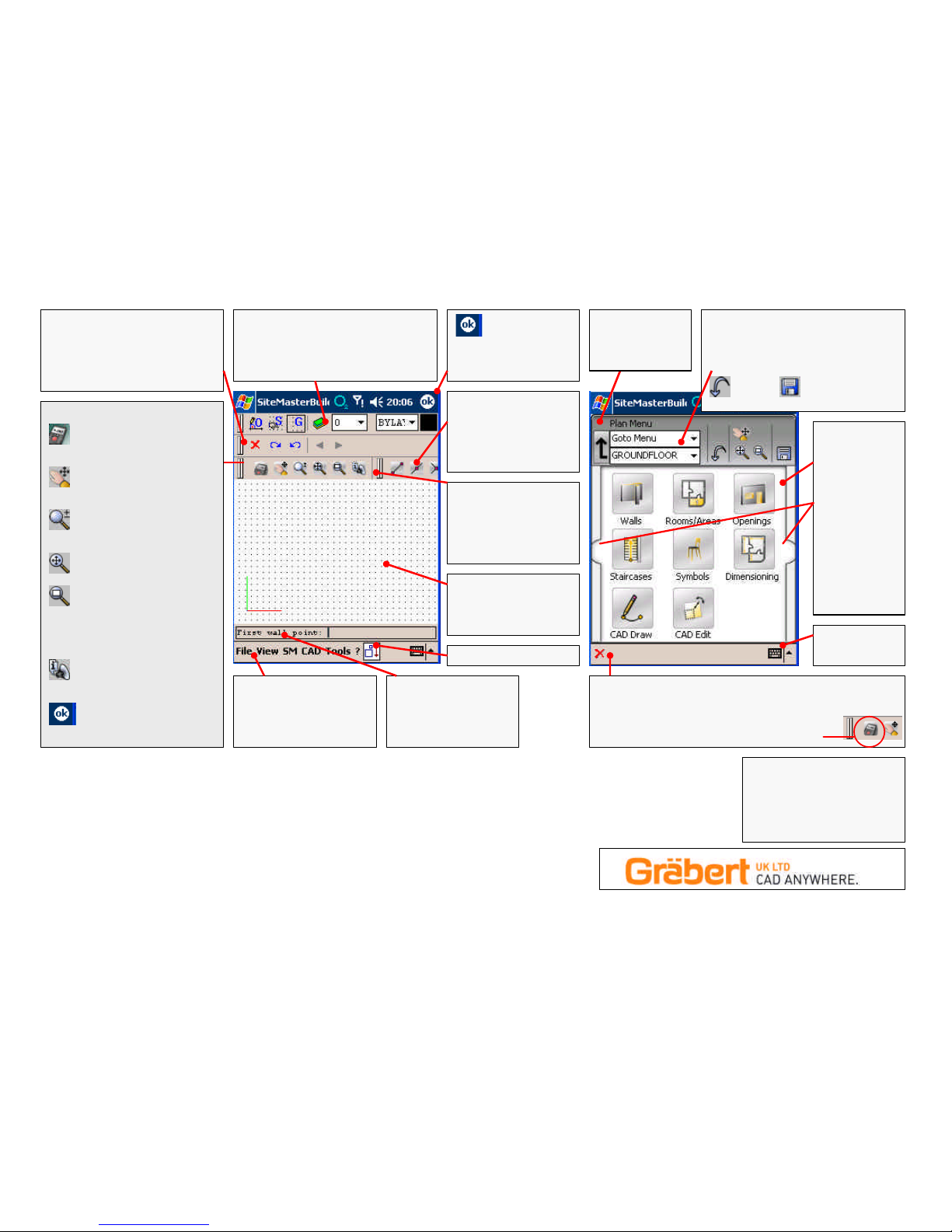
Screen Layout
Options toolbar…
This will and give you different options for
the particular command you are in.
The BLUE Arrows are REDO and UNDO
Use the grey/black arrows to scroll
through the options available
SiteMaster toolbar…
SiteMaster Menu ON/OFF
You can also use the main
menu…SiteMaster > Start Icon Menu
Pan tool… ‘Push’ the drawing
around on screen press again (or ESC)
to switch OFF
Zoom IN/OUT… Slide the stylus up
and down the screen to zoom in/out
press again (or ESC) to switch OFF
Zoom Extents… Shows the whole
drawing in the drawing window
Zoom Window… when picked,
needs 2 further points to be picked on
screen….these points will be the 2
diametrically opposite corners of a
box….the contents of which will fill the
screen.
Add Voice Note... Lets you record
your voice and place an icon in the
drawing
Enter...OK acts as the Enter key
Property toolbar….
Ortho lock, Snap to Grid, Grid ON/OFF
CAD Layer Manager, Current Layer, Current
Line Style, Current Colour
NOTE: SiteMaster will automatically use its
As is typical on
PDA’s. use the OK icon to
act as the ENTER key.
Use the Goto Menu to navigate between
SiteMaster modules
Use the Floor Manager drop down to control
which floor you are working on and access
SiteMasters floor manager tools.
.UNDO.and. SAVE…very useful
SiteMaster
Menu
system….
Pictorial access to
the SiteMaster
Building
commands…split
into modules for
easier working.
TIP For modules
with more than
one page of
commands, use
the arrows at the
side to turn the
pages.
HIDE/SHOW
Keyboard
SiteMaster Menu system
ON/OFF
….
To turn the SiteMaster menus OFF select this cross.
To turn the menus back on select Main Manu > SM > Start Icon Menu
Or
Click the SiteMaster icon on the end of the SiteMaster toolbar
SNAPS toolbar….
Use these to force
SiteMaster to ‘snap’ to a
specific point on an
object…the red dot shows
where the snap will occur
T
oolbar
Control
….
Use this vertical bar to move
toolbars around.
TIP: Click it once to ‘flood’
the toolbar onto the screen.
Click it again to re-dock the
Drawing window….
This is where you drawing
will appear…use the ZOOM
tools to navigate around it
HIDE/SHOW toolbars
Command Prompt….
This is where you can type
commands and you are
prompted for the next thing
to do in any command.
Main Menu….
all the
commands are available in a
‘drop down’ format
Load this extended menu by
selecting ‘File > Load extended
UP Arrow…
Use this to step back
up the menu
modules
Page 4
Us
eful TIPS for the Hilt
i
PD38
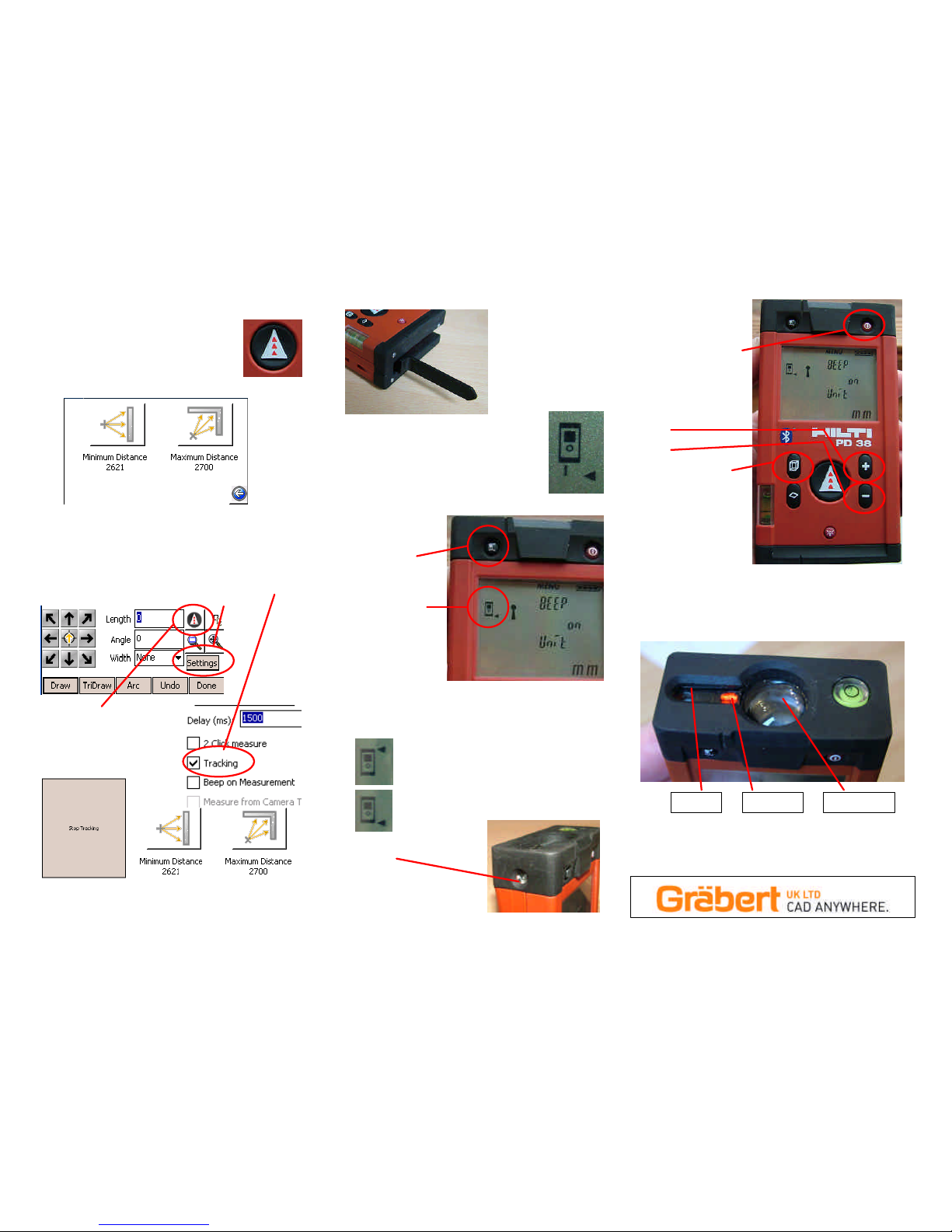
Using Tracking…MAX/MIN On the Hilti
Method 1….
Simply press and hold the DIST button until the Disto
starts beeping….then let go…press again to stop the
tracking. The measurements will be on the Disto
screen…select the one you want.
Or
Method 2….
There is another way to do the max/min on the Hilti….
Working in Tracking mode FIRING the Laser from the PDA’s
touch sensitive screen….
1. Switch on the ‘Tracking’ feature (While in most
commands you will see a ‘Settings’ button…select this to
access the ‘Device Settings’ dialogue box)
Now only use the DIST icons on
the PDA screen in SiteMaster to
‘fire’ the Laser.
2. Use the on screen
‘STOP TRACKING’
button to stop taking
measurements.
3. Select the Maximum or Minimum option as required.
4. When finished switch OFF the tracking by using the
‘Settings’ button again.
Whichever method you
use…utilize the fold out
aid in the base of the
Disto. Flick it out to the
extended position…the
only position for
measuring across
corners accurately
NOTE that the display will change to indicate
the measure position.
As you can see the arrow is connected to the
image of the aid.
Measuring from the Front or Back of the Hilti…
To switch to the front
measure position…
1. press the
front/back
button
When the front/back
button is pressed,
the disto will beep
and the display will
change.
WATCH OUT… the
next measurement
you take, it will still
be set on this setting
Press the front/back
button again to reset it.
TIP You can also fold out and replace the foot peg to restore
to the foot measuring position
Display when set to front of Disto
Display when set to foot of Disto
For longer distances use
the Sight…
Setting the Disto
Units, sound and
bluetooth…
Simply press and hold
the on/off button until the
Disto beeps twice and
then use the buttons on
the front of the disto to
change the according
setting.
BEEP
UNITS
BLUETOOTH ON/OFF
Once set just switch the
Hilti off and the settings
will be saved
Other Info…
The Hilti can measure down to a distance of 50mm, below this use
a tape measure or ruler..
The serial number that appears in the SiteMaster software can be
found on the back of the Disto.
Not always so obvious…don’t cover the receptor when taking
measurements.
Also, don’t cover the Laser
S
ight Laser Receptor
 Loading...