

Page 1

PD32
*282401*
282401
pt
Operating instructions 1–26
Mode d’emploi 27–52
Istruzioni d’uso 53–78
Manual de instruções 79–104
Manual de
instrucciones
105–130
en
fr
es
it
Page 2
5
2
4
8
3
1
7
10
9
9
6
10
Page 3
PDAW 80 / 81-2
PDA 50
PDA 60
PDA 61
PDA 62
PDA 70
PA 970 PDAW 80 / 81-3
PDAW 81-1
PDAW 80 / 81-1
PDAW 80-1
PDA 81
PDA 80
Page 4

1
PD 32 laser range meter Contents
It is essential that the operating
instructions are read before the range
meter is used the first time.
Always keep these operating instructions together with the tool.
Ensure that the operating instructions
are with the range meter when it is
given to other persons.
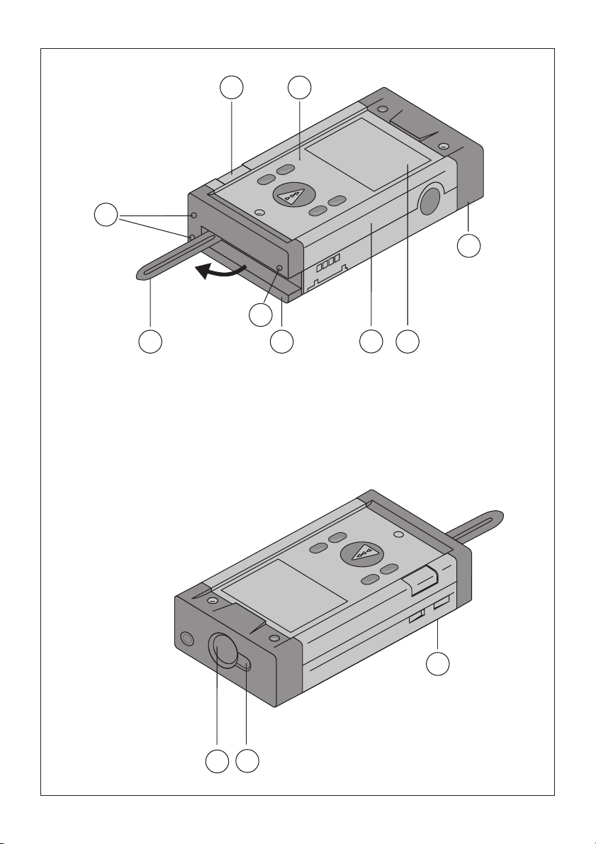
Component parts
Laser exit aperture
Control panel
Receiving lens
Plastic casing
Horizontal bubble
Vertical bubble
Battery compartment
Folding spike
Graphic display of operating status
Metal contact points for precise meas-
urement (3x rear)
Metal supports for precise measure-
ment (3x underneath)
Optical sight
Side measuring key
Contents
1. General information. . . . . . . . . . 3
1.1. Safety notices and their meaning 3
1.2. Pictograms . . . . . . . . . . . . . . . . . 3
1.3. Location of identification data on
the range meter . . . . . . . . . . . . . 3
2. Description. . . . . . . . . . . . . . . . . 4
2.1. Intended use. . . . . . . . . . . . . . . . 4
2.2. Items supplied . . . . . . . . . . . . . . 4
2.3. Measuring principle . . . . . . . . . . 4
2.4. Range meter functions . . . . . . . . 4
2.4.1. General range meter functions . . 4
2.4.2. PD 32 side measurement key. . . 4
2.4.3. PD 32 optical sight. . . . . . . . . . . 4
3. Tools and accessories . . . . . . . . 5
3.1. PDA 50 target plate. . . . . . . . . . . 5
3.2. PDA 80 / 81charging kits . . . . . . 5
3.3. PDAW 80-1 mains adaptor . . . . . 6
3.4. PDAW 80 / 81-2 car battery plug 6
3.5. PDAW 80 / 81-1 charging adaptor 6
3.6. PDAW 80 / 81-3 battery pack. . . 6
3.7. PDAW 81-1 mains adaptor . . . . . 6
3.8. PA 970 laser visibility glasses. . . 6
3.9. Belt clip PDA 62 . . . . . . . . . . . . . 6
4. Technical data . . . . . . . . . . . . . . 7
5. Safety information. . . . . . . . . . . 8
5.1. Basic safety information . . . . . . . 8
5.2. Misuse . . . . . . . . . . . . . . . . . . . . 8
5.3. General safety precautions . . . . . 8
5.4. Proper organization of workplace8
5.4.1. Electromagnetic compatibility. . . 9
5.4.2. Laser classification . . . . . . . . . . . 9
5.4.3. Transport . . . . . . . . . . . . . . . . . . 9
Page 5

2
Contents
6. Getting started. . . . . . . . . . . . . 10
6.1. Inserting alkaline / rechargeable
batteries . . . . . . . . . . . . . . . . . . 10
6.2. Battery charging . . . . . . . . . . . . 10
6.2.1. Standard charging of batteries . 10
6.2.2. Fast battery charging . . . . . . . . 11
6.3. Switching the range meter On
and Off . . . . . . . . . . . . . . . . . . . 11
6.3.1. Initial distances measurement . 11
6.4. Settings . . . . . . . . . . . . . . . . . . 12
6.4.1. Activating the setting menu . . . 12
6.4.2. Menu / Beep . . . . . . . . . . . . . . . 12
6.4.3. Menu / Units. . . . . . . . . . . . . . . 12
6.4.4. Terminating the menu. . . . . . . . 12
7. Operation . . . . . . . . . . . . . . . . . 12
7.1. General controls . . . . . . . . . . . . 12
7.1.1. Control panel . . . . . . . . . . . . . . 12
7.1.2. On and switch keys. . . . . . . . . . 12
7.1.3. Measure keys . . . . . . . . . . . . . . 13
7.1.4. Function keys . . . . . . . . . . . . . . 13
7.2. Display . . . . . . . . . . . . . . . . . . . 13
7.2.1. Symbols displayed . . . . . . . . . . 14
7.2.2. Display illumination . . . . . . . . . 15
7.3. Optical sight . . . . . . . . . . . . . . . 15
7.4. Measuring distances. . . . . . . . . 15
7.4.1. Measuring references . . . . . . . 15
7.4.2. Measuring distances step by step 16
7.4.3. Measurement mode . . . . . . . . . 16
7.4.4. Measuring from corners. . . . . . 17
7.4.5. Measuring with the aid of
target objects . . . . . . . . . . . . . . 18
7.4.6. Measuring in bright surroundings18
7.4.7. Taking measurements to
rough surfaces . . . . . . . . . . . . . 18
7.4.8. Taking measurements to
round or inclined surfaces . . . . 18
7.4.9. Taking measurements to
wet or shiny surfaces . . . . . . . . 18
7.4.10. Taking measurements to
transparent surfaces. . . . . . . . . 19
7.4.11. Measuring ranges. . . . . . . . . . . 19
8. Applications. . . . . . . . . . . . . . . 19
8.1. Measurement data memory . . . 19
8.1.1. Saving measurements . . . . . . . 19
8.1.2. Historical data memory. . . . . . . 20
8.2. Area measurement . . . . . . . . . . 20
8.3. Volume measurement. . . . . . . . 20
8.4. Adding distances . . . . . . . . . . . 21
8.5. Subtracting distances . . . . . . . . 22
8.6. Indirect measurement. . . . . . . . 22
8.6.1. Measuring criteria. . . . . . . . . . . 23
8.6.2. Selecting indirect measurement
options . . . . . . . . . . . . . . . . . . . 23
8.6.3. Indirect measurement
(combined version). . . . . . . . . . 23
8.6.4. Indirect measurement (simple
version). . . . . . . . . . . . . . . . . . . 24
8.7. Max / Min measurement. . . . . . 24
8.7.1. Max measurement . . . . . . . . . . 24
8.7.2. Min measurement. . . . . . . . . . . 25
8.7.3. Combined measurement. . . . . . 25
8.8. Setting out . . . . . . . . . . . . . . . . 26
9. Calibration and adjustment. . . 26
9.1. Calibration. . . . . . . . . . . . . . . . . 26
9.2. Adjustment . . . . . . . . . . . . . . . . 27
9.3. Hilti calibration service . . . . . . . 27
10. Care and maintenance. . . . . . . 27
10.1. Cleaning and drying . . . . . . . . . 27
10.2. Storage. . . . . . . . . . . . . . . . . . . 27
10.3. Transportation. . . . . . . . . . . . . . 27
11. Disposal. . . . . . . . . . . . . . . . . . 28
12. Warranty. . . . . . . . . . . . . . . . . . 28
13. FCC statement (applicable
in USA). . . . . . . . . . . . . . . . . . . 29
14. EC declaration of conformity. . 30
Page 6

3
1. General information
1. General information
1.1 Safety notices and their meaning
- CAUTION -
This word indicates a possibly hazardous
situation which could result in slight bodily
injuries or damage to property.
- NOTE -
This word indicates information to help the
user employ the product efficiently, and
other useful notes.
1.2 Pictograms
Warning signs
Symbols
These numbers refer to the
corresponding illustrations. The
illustrations can be found on the fold-out
cover pages. Keep these pages open when
studying the operating instructions. In
these operating instructions, the PD 32
laser range meter is referred to as "the
range meter".
1.3 Location of identification data on the
range meter
The type designation and serial number
can be found on the rating plate on the
range meter. Make a note of this data in
your operating instructions and always
refer to it when making an enquiry to your
Hilti representative or service department.
Type :
Serial-No.: ___________
General warning
Laser class 2
(Do not stare into the
beam.)
Read the operating
instructions before
use.
®
Hilti = registered trademark of Hilti Corporation,
Schaan, Liechtenstein
Type: PD 32
LASER RADIATION - DO NOT
STARE INTO BEAM
620-690nm/0.95mW max.
CLASS II LASER PRODUCT
This device complies with part 15 of the FCC Rules.
Operation is subject to the following two conditions:
(1) This device may not cause harmful interference,
and (2) this device must accept any interference received,
including interference that may cause undesired operation.
AVOID EXPOSURE
Laser radiation is emitted
from this aperture
DIN EN 60825-1:2003
Made in
Germany
2
s
1/4
319549 B/1.04
Page 7
4
2. Description
2. Description
The distance is determined along an
emitted laser beam up to the surface where
the laser beam is reflected. The red laser
spot clearly identifies the target from which
the measurement is taken.
The measuring range depends on the
reflectivity and the surface structure of the
target surface.
2.1 Intended use
The range meter is designed for the:
– Measurement of distances
– Calculation of areas, volumes and distances
– Addition and subtraction of distances
– Operation and storage in the specified
temperatures
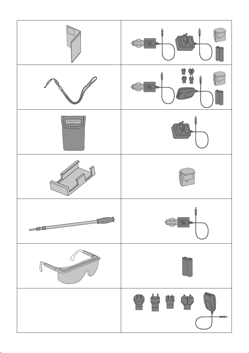
2.2 Items supplied
1 PD 32 laser range meter
1 PDA 50 target plate
1 PDA 60 hand strap
2 Type AA batteries
1 soft pouch
1 Operating instructions
1 Producer Certificate
2.3 Measuring principle
The range meter emits a visible laser beam
with measuring waves, which are reflected
returning with a phase shift. The phase
shift is used to determine the distance.
This measuring principle permits highly
accurate and reliable distance
measurements to objects without
special reflectors.
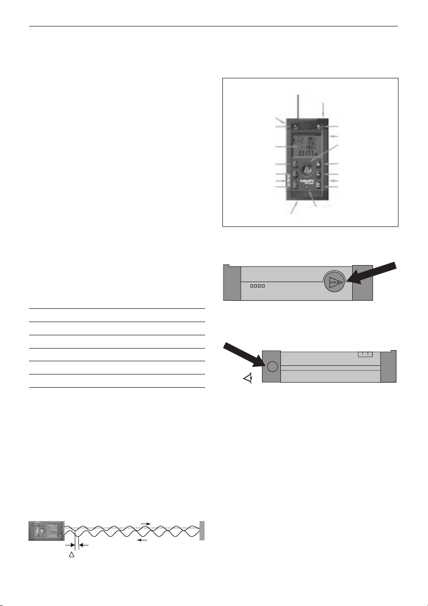
2.4 Range meter functions
2.4.1 General range meter functions
2.4.2 PD 32 Side measurement key
2.4.3 PD 32 Optical sight
Vertical bubble
Optical sight
Measurement reference
point
Liquid display
Volume function
Area function
Horizontal bubble
Pythagoras function
(indirect distance)
Spike Display illumination
On / off
Side measurement key
Measure key
Addition of distances
Subtraction of distances
Battery charging contacts
Max. / Min. function
Eye
phi
Page 8

5
3. Tools and accessories
3. Tools and accessories
Description Designation
Target plate PDA 50
Hand strap PDA 60
Soft pouch PDA 61
Belt clip PDA 62
Measuring extension PDA 70
Charging kit PDA 80
Charging kit PDA 81
Mains adaptor PDAW 80-1
Mains adaptor PDAW 81-1
Car battery plug PDAW 80/81-2
Charging adaptor PDAW 80/81-1
Battery pack PDAW 80/81-3
Laser visibility glasses* PA 970
* These are not laser safety
glasses and do not protect the
eyes from laser radiation. The
laser visibility glasses restrict
colour vision. Therefore these
are not permitted to be worn
by a person driving on a public
road, and must not be used
look straight into the sun.
3.1 PDA 50 target plate
The PDA 50 target plate is made of durable
plastic with a special reflective coating. In
poor light conditions, it is advisable to use
the target plate for distances above 10 m
(30 ft).
- NOTE -
– For reliable distance measurements the
laser beam should be perpendicular to
the target plate whenever possible. If this
not the case, the laser spot on the target
plate may not be in the same plane as
the target point and the distance
measured will be incorrect.
– For very accurate measurements using
the target plate, 1.2 mm (1/20 inch)
should be added to the measured
distances.
3.2 PDA 80 / 81 charging kits
The PDA 80 and PDA 81 charging kits
enables the use of the range meters with
rechargeable cells. The battery charging
time takes approx.12 hours for empty cells.
However, sufficient current is charged
within the first 15 minutes – for 150 - 200
measurements.
Please also refer to the description of
battery charging in section 6. Getting
started.
Contents of PDA 80 charging kit
– Mains adaptor 100 – 240 V AC
with 2-pole Europlug
– Car battery plug
– Charging adaptor for range meter
– 2 chargeable batter y cells (NiMH)
Contents of PDA 81 charging kit
– Mains adaptor 100 – 240 V AC
with 4 interchangeable plugs for US,
GB, AUS, EU.
Page 9

6
3. Tools and accessories
– Car batter y plug
– Charging adaptor for range meter
– 2 chargeable batter y cells(NiMH)
3.3 PDAW 80-1 mains adaptor
The mains adaptor is an integral part of the
charging kit. It is equipped with a two pin
plug. The mains adaptor transforms the
power supply from alternating current to
direct current which is used to charge the
batteries. The mains adaptor automatically
adjusts itself to suit an AC voltage between
100 - 240 V and 50 - 60 Hz. The mains
adaptor has been specially designed to
supply current to the charging adaptor.
- NOTE -
Battery chargers or mains adaptors with
other voltage outputs, such as those for
mobile phones, may not be used. Use of
other battery chargers or mains adaptors
may damage the range meter.
3.4 PDAW 80/81-2 car battery plug
The car battery plug is an integral part of
the PDA 80/81 charging kit. It can be
inserted into a vehicle cigarette lighter or
into sockets of the same design. This
adaptor has a special design and
transforms the 12 - 24 V direct current of
a vehicle battery into a voltage suitable for
the charging adaptor.
A light-emitting diode (LED) is
incorporated in the adaptor to indicate
correct connection for charging. An
additionalfuse in the adapters front section
provides protection against voltage peaks.
- NOTE -
As the car battery plug has been especially
designed to charge the NiMH batteries of
the PD 32, it may not be replaced by other
types of car battery plugs.
3.5 PDAW 80/81-1 charging adaptor
The respective mains adaptor supplies
current to the charging adaptor. Prior to
charging the battery, the side flange
connections should be carefully checked.
3.6 PDAW 80/81-3 battery pack
The battery pack consists of two
rechargeable, 1.2-V NiMH cells with a
capacity of approx.1800 mAh. The battery
pack remains in the battery compartment
while being charged.
- NOTE -
– A "memor y effect" is virtually
non-existent with this type of batteries
and the charging process used.
The charging process can be interrupted
at any time without damaging the
battery cells.
– Other brands of rechargeable batteries
can be used. It must be ensured,
however, that, as far as possible,
batteries have a similar capacity of
approx. 1800 mAh.
3.7 PDAW 81-1 mains adaptor
This mains adaptor PDAW 81-1 is virtually
identical to the PDAW 80-1 mains adaptor.
The only difference is the type of mains
plugs which are interchangeable plugs.
3.8 PA 970 laser visibility glasses
The laser visibility glasses clearly improve
the visibility of the laser beam (spot)
3.9 Belt clip PDA 62
The belt clip is made from durable plastics
and is quickly and easily fixed to the belt
using the snapper. For carrying the range
meter snaps into position and easily
detaches when being needed.
Page 10

7
4. Technical data
4. Technical data
Power supply
3 V DC
Type: AA (LR6, AM3, Mignon)
Standard: two alkaline primary cells
Optional: rechargeable NiMh cells
Battery status indicator
Battery display with four segments
showing 100%, 75%, 50% and
25 % charged
All segments deleted = empty battery
Measuring range
0.05 m to 200 m (2 inch to 600 ft)
0.05 m (2 inch) from the front edge
Max. distance resolution 750 m
(2,500 ft)
Typical measuring range without
target plate:
– Drywall panel, white70 m (210 ft)
– Concrete, dry 50 m (150 ft)
– Brick, dry 50 m (150 ft)
The maximum range depends on:
– Reflectivity of the target surface
– Ambient light conditions
In case measurements are not
possible, use the Hilti PDA 50
target plate.
Accuracy
±1.5 mm (±1/16 inch) is typical
for individual and continuous
measurements **
** The measuring accuracy is
affected by ± (1.5 mm + 20 ppm) /
±(1/16 inch + 20 ppm) due to
atmospheric conditions. This affect is
typically noticeable at distances >
100 m (> 300 ft).
Smallest unit displayed
1 mm (1/16 inch)
Beam diameter
< 6mm @ 10m (< 0,2 in @ 30 ft)
< 30mm @ 50m (< 1,2 in @ 150 ft)
< 60mm @ 100m (< 2,4 in @ 300 ft)
Basic operating modes
Single measurement
Continuous measurement
Calculation / Functions
Display
Illuminated liquid-crystal display
showing operating status and battery
status
Laser
Visible, 620 – 690 nm, laser class 2
(IEC60825-1:1993+A1:1997+A2:
2001/DIN EN60825-1: 2003;
CFR 21 § 1040 [FDA]
output power: < 1mW
Automatic time-out
Laser 1 min.
Range meter: 10 min.
Battery life at 25°C (77°F)
Max. number of measurements
with single set of batteries.
Alkaline: 15’000 - 20’000
NiMH: 8’000 - 10’000
Operating temperature
- 10°C…+ 50°C (14°F… 122°F)
Storage temperature
- 30°C…+ 70°C (- 22°F… 158°F)
Protection class
Dust and splash-proof, IP 54 as
per IEC529 standard
Weight
220 g / 0,48 lb (without batteries)
Dimensions
120 (L) x 65 (B) x 28 (H) mm
4,7˝ (L) x 2,5˝ (B) x 1,1˝ (H)
Page 11

8
5. Safety information
5. Safety information
5.1 Basic safety information
In addition to the safety precautions listed
in the individual sections of these operating
instructions, the following points must be
strictly observed at all times.
5.2 Misuse
The range meter and its accessories can
be a source of hazard if they are not used
properly or not used for the intended
purpose by untrained people.
– Do not use the range meter without
suitable prior instruction.
– Do not render any safety devices
ineffective and do not remove
information and warning notices.
– Have the range meter repaired only at a
Hilti service center. Unauthorized
opening of the range meter may cause
the emission of laser radiation in
excess of class 2.
– No changes or manipulations to the
range meter are allowed.
– Use only original Hilti accessories and
auxiliary tools in order avoid the risk of
injury.
– Do not use the range meter in
atmospheres where there is a risk of
explosion.
– Use only a clean, soft cloth for cleaning.
If necessary, moisten the cloth slightly
with pure alcohol.
– Keep the range meter out of the reach of
children.
– Measurements taken to plastic foam
materials, such as polystyrene foam, or
to snow or other strongly reflecting
surfaces, may be inaccurate.
– Taking measurements to surfaces with
low reflectivity surrounded by areas with
high reflectivity may lead to
measurement errors.
– Measurements taken through panes of
glass or other objects may be inaccurate.
– Rapid changes of the measuring
conditions, e.g. persons walking through
the laser beam, may lead to
measurement errors.
– Do not direct the range meter towards
the sun or other sources of bright light.
– Do not use the range meter as a levelling
tool.
– If you do not check the range meter
before taking important measurements
and after it has been dropped or
subjected to other mechanical stressing.
– No checking of the setting of the
measuring reference before measuring.
5.3 General safety precautions
Check the range meter for possible damage
before use. If the range meter is found to
be damaged, have it repaired at a Hilti
service centre. The accuracy of the range
meter must be checked after it has been
dropped or subjected to other mechanical
stressing.
– When the range meter is brought into a
warm environment from very cold
conditions, or vice versa, allow it to
become acclimatised before use.
– Although the range meter is designed for
the tough conditions of jobsite use, it
should be treated with care, as other
optical instruments (binoculars,
spectacles, cameras, etc.)
– Although the range meter is protected to
prevent entry of dampness, it should be
wiped dry each time before being put
away in its transport container.
– As a precaution, check the settings you
have made before using the range meter.
Page 12

9
5. Safety information
– When using the circular bubble level
(bull's eye) for alignment, only look at
the range meter from the side.
5.4 Proper organization of workplace
– Secure the area in which you are
measuring. When setting up the range
meter, take care to avoid directing the
beam towards yourself or other people.
– Avoid unfavourable body position when
working on ladders or scaffolding. Make
sure you have a stable stance and avoid
danger of overbalancing at all times.
– Measurements taken through panes of
glass or other objects may be inaccurate.
– Use the range meter only while observing
the specified operating conditions, i.e.
not directed towards a mirror, bright
chromium steel, polished stone, etc.
– Observe the accident prevention regula-
tions in force in the country you are
working.
5.4.1 Electromagnetic compatibility
Although the range meter complies with
the strict requirements of the relevant
guidelines, Hilti cannot entirely rule out
the following possibilities:
– The range meter might cause
interference to other equipment, e.g.
aircraft navigational equipment.
– The range meter might be subject to
interference caused by powerful radiation, which can then lead to incorrect
operation. Check the readings for
plausibility when measuring in these
conditions or if you are unsure of the
results.
5.4.2 Laser classification
The range meter conforms to laser class 2
based on the IEC60825-1:1993+A1:
1997+A2: 2001 /DIN EN60825-1:2003;
standard and class II based on CFR 21 §
1040 (FDA). These range meters may be
used without need for further protective
measures. The eyelid closure reflex protects
the eyes if a person looks into the beam
unintentionally for a brief moment. The
eyelid closure reflex can, however, be negatively influenced by medication, alcohol or
drugs. Nevertheless, as with the sun, a person should not look directly into sources of
bright light. The laser beam should not be
directed towards persons.
Laser information plates based on
IEC60825-1:1993+A1:1997+ A2: 2001/
DIN EN60825-1:2003;
Laser information plates for the US
based on CFR 21 § 1040 (FDA)
This laser product complies with 21 CFR
1040, as applicable.
5.4.3. Transport
Remove the alkaline or rechargeable
batteries whenever transporting the
range meter.
Page 13

10
6. Getting started
6. Getting started
6.1 Inserting alkaline / rechargeable
batteries
- CAUTION -
– Observe the polarity of the batteries.
(refer to signs inside the battery
compartment.)
– Make sure the battery compartment is
properly locked.
1.Lightly press the lid of the battery
compartment.
2.Slide the lid out and off.
3.Replace the batteries.
- NOTE -
For alkaline batteries
– Always replace a complete set of
batteries.
– Do not mix used and new batteries.
– Do not mix batteries of different makes
or types.
– Use only undamaged batteries of an
approved type.
For rechargeable batteries
– Always use rechargeable batteries of the
same make and same type.
– Always use rechargeable batteries of the
same age and charged to the same level.
– New rechargeable batteries are mostly
empty and have to be charged prior to
first use.
– Use only NiMH batteries with 1.2 V
and 1500 – 2000 mAh capacity.
6.2 Battery charging
6.2.1 Standard charging of batteries
The charging process ensures that the
there will be no "memory effect". In view
of this, charging can begin at any time
regardless of the level to which the battery
is already charged.
Attach the PDAW 80/81-1 charging adaptor
into the range meter .
For charging, either connect the mains
adapter or the car battery plug to the
charging adaptor.
The maximum. charging time is 12 hours.
As with many mobile phones, the level of
charging is shown by movement of
battery display segments.
6.2.1.1 Battery charging level display
– The level of charging is indicated by
moving battery status segments
at the top on the right of the display.
– When a battery is fully charged,
“ “ (battery full) will be
displayed.
FullAccu
1
2
2
Page 14

11
6. Getting started
6.2.1.2 Charging display for unintention-
ally inserted alkaline batteries
– If alkaline batteries are identified, all
battery status segments flash continually
to indicate missing rechargeable
batteries. Additionally, they sign “
“ shows in the display.
The range meter cannot be switched on.
– If defective or non re-chargeable alkaline
batteries are inserted, the battery display
will flash and, at the same time,
“ “ (defective battery) will
appear in the display.
- NOTE -
– At any time while the batteries are being
charged, the range meter can be
switched on and used. The battery charging process stops when the range meter
is switched on and the laser activated.
– Rechargeable batteries discharge if they
are stored for a long time. The battery
charging process terminates after 1
minute when charging very empty
rechargeable batteries and the display
switches off in this case, the charging
process can be re-started only by
disconnecting the range meter from the
mains adaptor or by removing / replace
the rechargeable batteries.
– Keep the range meter in a safe place.
6.2.2 Fast battery charging
The charging process ensures that within
15 minutes of charging with the PDAW
80/81-2 car battery plug the battery
receives enough power for a further
150 to 200 measurements.
This process in combination with car
battery plug is a particular advantage if
the user needs the range meter ready for
use quickly.
dEFAccu
Accu
no
6.3 Switching the range meter On and Off
The range meter is switched on or off by
pressing the "On / Off" key.
After being switched on, the range meter is
in the basic display mode.
6.3.1 Initial distance measurement
Press the "Measure" key once.
This will switch on the range meter and
the laser beam if the range meter was
switched off.
If the range meter is already switched on,
this will activate the laser beam.
Aim the visible laser spot at a target about
3 to 10 (10 – 30 ft) meters away.
Press the "Measure" key again.
The distance will be shown in less
than 1 second, e.g. 5.489 m (16.296 ft).
You have taken the first distance
measurement with the PD 32 range meter.
Page 15

12
6. Getting started / 7. Operation
6.4 Settings
6.4.1 Activating the setting menu
The menu is activated by pressing the
"On / Off" key pressed for about 2 seconds
while the range meter is switched off.
The beep and the units may be set
6.4.2 Menu / Beep
The key “Plus” switches between the "On"
and "Off" modes.
Setting Option
Beep On
Off
6.4.3 Menu / Units
The key “Minus” switches between the
units, as shown below.
Setting Distance Area Volume
m meters m2m
3
mm millimeters m2m
3
ft feet (decimal) feet2feet
3
yd feet (decimal) yard2yard
3
in inch (decimal) inch2inch
3
in 1/8 feet & inch 1/8 feet2feet
3
in1/16 feet & inch 1/16 feet2feet
3
6.4.4 Terminating the menu
The menu is terminated by pressing the
"On / Off" key. All settings displayed will be
saved.
Beep
Units
7. Operation
7.1 General controls
7.1.1 Control panel
7.1.2 On and switch keys
ON / OFF
– switches the range meter
on and off.
Measuring reference point
– switches the measuring ref-
erence between front
and rear .
Display illumination
– switches the display
illumination On and Off.
MENU
on
m
BEEP
Unit
Page 16

13
7. Operation
7.1.3 Measure keys
"Measure" key
– switches the range meter On
– activates the laser beam
for aiming at the target,
– activates single distance
measurement
– activates and deactivates
continuous distance
measurement.
Side "Measure" key
– activates the laser beam for
aim ing at the target,
– activates individual distance
measurement
– activates and deactivates
continuous distance
measurement.
7.1.4 Function keys
Calculation functions are activated by
pressing the relevant function keys. When
a measurement using a function has been
carried out incorrectly or unintentionally,
the function can be reset at any time by
pressing the same function key again or
any other function key.
Volume
– activates the "volume"
function and deactivates
every other function.
Area
– activates the "area" function
and deactivates every other
function.
Plus
– activates the "distance
addition" function and
deactivates every other
function.
Minus
– activates "distance
subtraction" and deactivates
every other function.
Indirect distance
measurement
– activates the "Indirect
Measurement" function
and deactivates every other
function.
Min. / Max.
– activates the "MIN. / MAX."
function and deactivates
every other function.
7.2 Display
The display shows the measurements,
settings and range meter status.
In the measuring mode, the latest readings
are shown in the lowest display line (result
line) and the prior readings in the lines
above. For such functions such as area,
volume, Pythagoras, etc., the measured
distances are displayed in the intermediate
lines and the calculated result appears in
the lowest display line (result line).
Page 17

14
7. Operation
7.2.1 Symbols displayed
Temperature too high
> +50 °C (122 °F)
Action:
Allow the range meter to cool
down.
Temperature too low
< -10 °C (14 °F)
Action:
Warm up the range meter.
Unfavourable signal
conditions
Insufficient reflected laser light
Action:
– Keep the measuring
distance > 50 mm (2 inch)
from the front edge.
– Clean the lens.
– Take a measurement from
another surface or use the
target plate PDA50.
Ambient light at target too
bright Action:
– Shade the target from bright
light or use the target plate
PDA50.
Laser switched on
– moving dashed line
Display reference status
– Front edge
– Rear edge
– Spike
– Spike (flashing) – adds
automatically 1.270 m/ 50
inch to measurements
Battery status
– 4 segments = 100% full
– 3 segments = 75% full
– 2 segments = 50% full
– 1 segment = 25% full
– 0 segments = empty
Batteries empty
Action:
– Replace batteries.
– Re-charge rechargeable
batteries
Menu activated
Line with MIN distance
(shortest distance)
Line with MAX distance
(longest distance)
Display distances differences
– Difference between MAX
and MIN. distances
Historical data mode active
– Display the previous 5
measurements or complete
functions results including
graphics
General hardware error
Switch the range meter Off
and then back On. If the error
persists, notify the local Hilti
service centre.
Indirect distance
measurement
Switches between two
options:
– Single rectangular
triangle
– Double rectangular
triangles
Volume measurement active
Area measurement active
Page 18

15
7. Operation
7.2.2 Display illumination
= Illumination key
The illumination key, switches the display
illumination On or Off. In the dark or in
very bright light, e.g. sunlight or a strong
spotlight the display illumination helps the
user to read the display more easily.
- NOTE-
Display illumination consumes additional
power. If it is used frequently, a shorter
battery life must be expected.
7.3 Optical sight
The built-in optical sight is a great benefit
when measuring outside and whenever the
laser spot is poorly visible. Thanks to the
optical sight, even at long distances can be
easily and precisely aimed at. Whenever
the rangemeter’s laser is On, the laser spot
can be seen in the optical sight. If the laser
spot is not visible in the optical sight,
either the measurement is completed or
the laser beam has switched off, the timer
of 60 seconds may have expired.
The optical sight runs parallel to the laser
beam.
Typical measuring procedure with the
optical sight
– Press the "Measure" key to activate
the laser beam.
– Aim for the target with the laser spot in
the optical sight.
– Press the "Measure" key or "Side
measure" key keep aiming until the laser
spot in the optical sight disappears.
– Read the distance in the display.
Diagram of optical sight
- NOTE -
It is practical for the optical sight to be
used for distance above 10 m (30ft).
7.4 Measuring distances
Distance measurements can be taken to all
“non-cooperating” stationary targets, i.e.
concrete, rock, wood, plastic, paper, etc.,
The use of prisms or other strongly
reflecting targets is not permitted and, if
used, might falsify the results.
7.4.1 Measuring references
= switch key
The range meter can measure distances
from three different measuring reference
points.
By pressing the "switch" key on the left at
the front of the range meter the measuring
reference point toggles between front edge
and rear edge. If the spike is folded out
90°, the reference position is set to the
end of the spike.
The reference for the measuring extension
PDA70 is activated when the range meter
is switched off. While the reference key
(upper left) is pressed and the range meter
switched On with the On/Off key (upper
right) the spike symbol starts blinking in
the display. The reference for the measuring extension is deactivated when the
range meter is switched Off.
Laser
Sighting
Eye
Page 19

7. Operation
Display Reference position
Front edge
Rear edge
End of spike
Measuring extension PDA70
Spike (flashing)
extends by1.270m/50 inches
- NOTE -
– If the spike is folded out 180°, reference
point is always automatically set to the
rear edge.
7.4.2 Measuring distances step by step
The range meter measures distances in a
very short time and, when doing so, shows
various information in the display.
1. Switch on the range meter by pressing
the "On" key.
2. Press the "Measure" key once. This
switches on the red laser beam which
is visible as a laser spot on the target
surface. The display shows this aiming
mode as an animated dashed line
16
3. Aim to the target.
4. Press the "Measure" key once again
to measure the distance.
The result appears in the result line
normally in less than a second. The laser
beam switches off.
If further measurements are taken, up to
three previously determined distances are
shown in the intermediate result lines,
i.e. a total of the last four measured
distances are shown.
7.4.3 Measuring mode
Two different measuring modes are
available to measure distances. These are
single distance measurement and
continuous distance measurement. The
continuous measurement mode is used for
setting out given distances or offsets and
is also used where distance measurements
are more difficult, e.g. to corners, edges,
niches, etc.
Page 20

7. Operation
17
7.4.3.1 Single distance measurement
(Measure key)
1.Switch on the laser beam by pressing
the "Measure" key.
2.Press the "Measure" key once again.
Generally, the measured distance will be
completed in less than a second and
shown in the result line.
- NOTE -
Alternatively the range meter may be
switched on by pressing the On key and
the laser then activated by pressing the
measure key.
7.4.3.2 Continuous measurement
Press the "Measure" key for about 2 seconds to activate this measuring mode.
When doing so, it does not matter whether
or not the range meter is off or the laser
beam is switched on or off. The range
meter will always switch to continuous
measurement.
During continuous measurement, the distances are updated in the result line by
about 8 to 15 measurements every second.
This depends on the reflectivity of the
target surface.
If the beep signal is switched on, continuous measurement is indicated by a Beep.
The measuring process is stopped by
pressing the "Measure" key once again. On
doing so, the last valid distance
measurement shows in the result line on
the display.
- NOTE -
Continuous measurement is possible
wherever distances can be measured. This
applies also to functions, such as areas
and volumes.
7.4.4 Measuring from corners
The spike is used when measuring
diagonally across rooms or from
inaccessible corners.
1. Fold out the spike 90°.
This automatically sets the measuring
reference to the end of the spike. The
range meter takes the extended
reference point into account and
corrects the measured distances
accordingly.
2. Position the range meter with the spike
at the desired starting point for the
measurement and aim towards the
target.
3. Press the "Measure" key. The measured
distance will appear in the display.
Page 21

18
7. Operation
7.4.5 Measuring with the aid of target
objects
When taking measurements to exterior
corners, e.g. on buildings, perimeter
fences, etc., boards, bricks or other
suitable objects can be used as the target.
Use of the PDA 50 target plate is
recommended for long distances and in
unfavourable light conditions, e.g. strong
sunlight.
7.4.6 Measuring in bright surroundings
The PD 32 has a built-in optical target
sight. When measuring to very bright
surfaces, the laser spot is often not visible.
Thanks to the laser spot superimposed in
the optical sight, you can always clearly
and reliably aim at the target.
For long distances and bright light
conditions, we recommend the use of
the PDA 50 target plate.
7.4.7 Taking measurements to rough
surfaces
When measuring to rough surfaces, e.g.
coarse render, stucco, etc, an average distance value is measured weighting the centre of laser spot higher that the edges of
the laser spot.
7.4.8 Taking measurements to round or
inclined surfaces
If surfaces of this kind are aimed to an
obtuse angle, inadequate light energy or,
when aimed perpendicular, measurements
may refer to the reflected laser spot from
elsewhere. In both cases we recommend
the use of the PDA 50 target plate
7.4.9 Taking measurements to wet or
shiny surfaces
As long as the range meter can be aimed
towards the surface, a distance to the
target will be reliably measured. In the case
of highly reflective surfaces, a reduction in
the range or a measurements to the actual
light reflex from elsewhere must be
expected.
Page 22

19
7. Operation / 8. Applications
7.4.10 Taking measurements to
transparent surfaces
It is not possible to measure distances to
transparent materials, e.g. liquids, foam
polystyrene, etc. This is because light penetrates these materials and therefore measuring errors may occur. If
measurements are taken through glass,
measuring errors may also occur.
7.4.11 Measuring ranges
7.4.11.1 Increased distances
– Taking measurements in the dark, at
dawn, dusk and to shaded targets or
with the front of the range meter shaded,
generally leads to an increase of the
measuring range.
– Taking measurements to the PDA 50
target plate also results in an increase of
the measuring range.
7.4.11.2 Reduced distances
– Taking measurements in very bright
ambient light, e.g. in sunshine or a very
bright spotlight etc, can lead to a reduced
distances.
– Taking measurements through glass or
other objects in the target beam can lead
to a reduced measuring range.
– Taking measurements to matt green, blue
or black, wet or shiny surfaces can lead
to a reduced measuring range.
8. Applications and calculation
functions
The individual steps within all functions are
mostly supported, on principle, by graphics
on the display.
- NOTE -
– Continuous measurement can be used
within all functions where single
measurements are possible.
– If measuring errors occur during
continuous measurement or if
continuous measurement is stopped by
pressing the "Measure" key again, the last
valid distance will be shown.
8.1 Measurement data memory
While measuring, the range meter continuously saves the measured values and the
results of calculations.
8.1.1 Saving measurements
When measuring several distances, up to
three previous distances, are displayed in
the intermediate result lines. This means
that in total the last four measured
distances are displayed or saved.
4. measured value
3. measured value
2. measured value
1. last measured
value
Page 23

20
8. Applications
8.1.2 Historical data memory
The range meter saves the last five
measurements or calculation including the
graphics. Always displays immediately after
the range meter is switched On with the
On/Off-key, before any function is activated
or before the “Measure” key is pressed,
these data can be recalled from the memory and displayed one by one using the
“Plus/ Minus” key.
The symbol “Historical data mode active”
shows the data stored in the memory.
Example of the display of a saved volume
measurement:
8.2 Area measurement
Areas can be determined easily and quickly.
Press the "Area" function key. This switches
the laser beam on – ready for measuring.
The individual steps for determining an
area are supported by a corresponding
graphic display. To determine the floor
space of a room, for example, the following
procedure must be followed:
a
b
= a . b
1. At the start of the area function, the
laser beam is switched on.
2. Aim the range meter at the target.
3. Press the "Measure" key.
The room width will be measured
and shown.
4. After this, the graphic display will
automatically request measurement
of the room length.
5. Aim the range meter at the next
target to obtain the room length.
6. Press the "Measure" key.
The second distance will be measured,
the area immediately calculated and
the result shown in the result line.
Both distances required to calculate the
area appear in the intermediate result lines
and can be conveniently noted after the
measurements and the calculation.
- NOTE -
To determine another area, press the "Area"
function key again.
8.3 Volume measurement
Volumes can be determined in one
measuring operation.
Press the "Volume" function key. This
switches the laser beam on – ready for
measuring.
MEN
x
+
-
I
=
PD 25
m
67.784
5.489
m
m
12.349
2
Page 24

21
8. Applications
The individual steps for determining a
volume are supported by a corresponding
graphic display. To determine the volume
of a room, for example, the following
procedure must be followed:
1. At the start of the volume function,
the laser beam is switched on.
2. Aim the range meter towards at the
target.
3. Press the "Measure" key.
The room width will be measured and
shown.
4. After this, the graphic display will
automatically request measurement
of the room length.
5. Aim the range meter at the next target
to obtain the room length.
6. Press the "Measure" key.
The room length will be measured.
7. After this, the graphic display will
automatically request measurement
of the room height.
8. Aim the range meter at the next target
to obtain the room height.
9. Press the "Measure" key.
The room height will be measured, the
volume immediately calculated and
the result shown in the result line.
All three distances required to calculate
the volume appear in the intermediate
result lines and can be conveniently noted
after the measurements and the calculation.
- NOTE -
To determine another volume, press the
"Volume" function key again until the
graphic symbol for “Volume” appears.
8.4 Adding distances
Single distances can be conveniently added.
This is useful for determining door or
window openings or to add several partial
distances to form the perimeter.
1. Press the "Measure" key.
(The laser beam will be switched on).
2. Direct the range meter towards
the target.
3. Press the "Measure" key.
The first distance will be measured
and shown.
(The laser will be switched off.)
4. Press the "Plus" key to add the next distance. The first distance will appear in
the middle intermediate result line and
a plus sign in the lowest one.
(The laser beam will be switched on.)
5. Aim the range meter at the next target.
6. Press the "Measure" key.
The second distance will be measured
and shown in the bottom intermediate
result line. The calculation result will
appear in the result line at the same
time.
The current total of the distances is always
shown in the result line.
This procedure can be repeated until all
distances have been added.
To terminate the addition of distances,
simply measure a distance without first
MEN
x
+
-
I
=
PD 25
MEN
x
+
-
I
=
PD 25
MEN
x
+
-
I
=
PD 25
MEN
x
+
-
I
=
PD 25
MEN
x
+
-
I
=
PD 25
MEN
x
+
-
I
=
PD 25
Page 25

22
8. Applications
pressing the "Plus" key. The previous three
measurement and calculation results will
be in the intermediate displays.
8.5 Subtracting distances
Single distances can be conveniently
subtracted from each other. This is useful
for determining, for example, offsets to
inaccessible places or the distance from
the underside of a pipe to the ceiling. To do
so, the distance from the floor to the
underside of the pipe is subtracted from
the distance from the floor to the ceiling. If,
additionally, the pipe diameter is deducted,
the result is the distance from the top of
the pipe to the ceiling.
1. Press the "Measure" key.
(The laser beam will be switched on.)
2. Aim the range meter at the target.
3. Press the "Measure" key.
The first distance will be measured and
shown.
(The laser beam will switch off.)
4. Press the "Minus" key for subtraction.
The first distance will appear in the
middle intermediate result line and a
minus sign in the lowest one.
(The laser beam will switch on.)
5. Aim the range meter at the next target.
6. Press the "Measure" key.
The second distance will be measured
and shown in the bottom intermediate
result line. The result of the subtraction
will appear in the result line.
The current difference between
distances is always shown in the
result line.
879
546
213
.
0
=
C
I
PD 28
?!
+
x
879
546
213
.
0
=
C
I
PD 28
?!
+
x
?
This procedure can be followed until all
distances have been subtracted.
To terminate the subtraction of distances,
simply measure a distance without first
pressing the "Minus" key. The previous
measurement and calculation results will
be shown in the intermediate displays.
8.6 Indirect measurement
An indirect distance can be determined by
taking several distance measurements and
calculating according to Pythagoras's
theorem.
The functions for indirect measurement are
called by pressing the "Indirect distance
measurement" function key.
When doing so, there are two possibilities:
the combined version using three
measured distances
(Press the function key
once.)
the simple version using two
measured distances
(Press the function key
twice.)
The simple version is suitable when a
rectangular reference exist such as two
perpendicular walls or a floor adjacent
to a vertical wall.
The combined version is more suitable for
a free determination where it is not
possible to measure a perpendicular distance to one end of the distance to
be calculated.
- NOTE -
The result of indirect measurement is, due
to principle less accurate than direct
Page 26

23
8. Applications
measurements. To obtain the best possible
result, attention must be paid to the geometry, e.g. right angle and triangle
arrangement. The best results are
obtained when:
a) the tool is aimed accurately at the ends
of the line
b) all points measured are in one single
plane
c) measuring is carried out closer to the
object rather than far away.
8.6.1 Measuring criteria
The indirect measurement function verifies
the triangular geometry as the measurements are taken. The angle of the
triangle(s) at the range meter’s position is
checked and must be greater than 10°.
Otherwise a double beep indicates an error,
the function terminates and all previous
measurements are lost. The function automatically restarts.
The most reliable results are achieved with
the closest offset to the object. Additionally
when using the combined version (doubletriangle), both triangles should be almost
the same size.
8.6.2 Selecting indirect measurement
options
Pressing the "Indirect distance
measurement" function key, activates the
combined version first. Pressing the
"Indirect distance measurement" function
key once again, switches to the simple
version. Pressing this key a third time,
switches from this function back to the
normal display mode.
8.6.3 Indirect measurement
(combined version)
>10°
>10°
>10°
The individual steps for indirect distance
determination are supported by
corresponding graphics on the display.
To use the combined version, for example,
the following procedure must be observed:
1. After starting the "Indirect
measurement" function, the laser beam
will be switched on and the combined
version activated.
2. Aim the range meter at one end of the
line to be determined as indicated on
the graphic display.
3. Press the "Measure" key.
4. Thereafter, the graphic display will
automatically request measurement of
the perpendicular distance. Here,
particular care must be taken to
measure this distance in the continuous
measurement mode in order to
determine the point with the shortest
(perpendicular) distance more reliably
5. Move over the point in the area of suspected minimum distance from the tool
with and stop the measurement by
pressing the "Measure" key.
6. The tool requests measurement of the
other end of the line. Aim the tool at
this point and press the "Measure" key.
7. After the last distance has been
measured, the range meter will
immediately calculate the indirect distance.
90∞
90∞
Page 27

24
8. Applications
8.6.4 Indirect measurement
(simple version)
The individual steps for indirect distance
determination are supported by
corresponding graphics on the display.
To use the simple version, the following
procedure must be observed:
1. Press the "Indirect measurement"
function key twice to select the simple
version. .
The laser beam will switch on.
2. Aim the range meter at the target
indicated on the graphic display.
3. Press the "Measure" key.
4. Thereafter this, the graphic display will
automatically request measurement
of the shortest distance.
5. After the second measurement has
been completed, the range meter will
immediately calculate the indirect distance.
8.7 Min / Max measurement
The minimum / maximum (Min / Max)
function is used primarily for determining
diagonal distances or taking measurements
to inaccessible places and determining or
setting out parallel objects.
? m (? ft
)
90∞
P
D
2
2
M
E
N
=
1
x
+
-
P
D
2
2
M
E
N
=
1
x
+
-
P
D
2
2
M
E
N
=
1
x
+
-
Both functions are activated simultaneously
by pressing the "Min / Max" key.
In addition, the difference between
minimum and maximum is shown.
8.7.1 Maximum measurement
The continuous measurement mode is
used for the maximum measurement and
this mode updates the display every time
the measured distance increases.
1. After starting the "Min / Max" function,
the laser beam will switch on.
2. Aim the range meter towards the target.
3. Press the "Measure" key.
4. After this, continuous measurement
will start.
5. The distance shown in the "MAX" display field will update every time the distance increases above the last value
displayed.
6. The distance shown in the MIN display
field will update every time the
measured distance decreases below
the last value displayed.
7. Stop measuring by pressing the
"Measure" key.
The display then shows values for the Max
distance, Min distance and the difference
between the two values.
90∞
90∞
90∞
90∞
M
E
N
x
+
-
I
=
P
D
2
2
L
A
S
E
R
M
E
N
x
+
-
I
=
P
D
2
2
L
ASE
R
Page 28

25
8. Applications
8.7.2 Minimum measurement
The minimum measurement is taken in the
continuous measurement mode which
updates the display every time the
measured distance decreases.
1. After starting the "Min / Max" function,
the laser beam will be switched on.
2. Aim the range meter towards the target.
3. Press the "Measure" key.
4. After this, continuous measurement
will start.
5. The distance shown in the "MIN" display
field will update every time the distance
decreases below the last value
displayed.
6. The distance shown in the "MAX" display
field will update every time the distance
increases above the last value
displayed.
7. Stop measuring by pressing the
"Measure" key.
The display then shows values for the
Max distance, Min distance and difference
between the two values.
x1 = x
2
8
7
9
5
4
6
2
1
3
.
0
=
C
I
PD 28
?!
+
x
8
7
9
5
4
6
2
1
3
.
0
=
C
I
PD 28
?!
+
x
8
7
4
C
P
D
2
8
8.7.3 Combined measurement
The combination of simultaneous display
of maximum and minimum distances
permits the calculation of offsets,
differences in distances very simply,
quickly and reliably. As a result, how much
the offset between a pipe and a ceiling or
the offset of two objects in general, can be
determined reliably even if they are in
inaccessible places.
1. After starting the "Min / Max" function,
the laser beam will switch on.
2. Aim the range meter towards the target.
3. Press the "Measure" key.
4. After this, continuous measurement
will start.
5. Move the range meter so that the
longest and the shortest distances
are measured.
6. The difference between the two
distances is shown in the line
In the given example, the difference in distance between ceiling and underside pipe
can be read straight off the display.
879
546
213
.
0
=
C
I
PD 28
?!
+
x
879
546
213
.
0
=
C
I
PD 28
?!
+
x
?
Page 29

26
8. Applications / 9. Calibration and adjustment
8.8 Setting out
With the range meter, pre-determined
dimensions can be set-out and marked,
such as for installing drywall tracks.
The continuous measurement mode is
used when transfering dimensions from
drawings. (See also section 7.4.3.2
Continuous measurement.)
Hold the "Measure" key pressed for approx.
2 seconds to activate the continuous
measurement mode. When doing so, it
does not matter whether the range meter is
switched off or the laser beam is switched
on or off. The range meter always switches
to the continuous measurement mode.
Move the range meter slowly until the
desired distance is reached or appears in
the display.
Press the "Measure" key once again to end
the continuous measurement mode.
9. Calibration and adjustment
9.1 Calibration
The inspection, measuring and test
equipment for the range meter must be
certified in accordance with ISO 900X...
You may carry out the inspection,
measuring and test of the PD 32 laser
range meter as specified in ISO 900X...
(See ISO 17123-4 Field Process for
Accuracy Examinations of Geodetic
Instruments:
Part 6, Close-range Opto-electrical Range
Meters.)
Select a readily accessible measuring distance of a known length approx. 1 to 5
meters (3 – 15 ft) long which does not
vary with time and take five measurements
of the same distance.
Determine the mean of the deviations to
the known distance. This value should be
within the specific accuracy tolerance for
the range meter.
Keep a record of this value and note the
time for the next test.
Repeat this check measurement at regular
intervals as well as before and after
important measuring tasks.
Apply a sticker to the PD 32 documenting
this control of the measuring, inspection
and test equipment for the range meter and
keep a record of the entire control process,
inspection procedure and the results.
Please refer to the technical data contained
in the operating instructions and the
information concerning measuring
accuracy.
Page 30

27
9. Calibration and adjustment / 10. Care and maintenance
9.2 Adjustment
For optimized adjustment, have the laser
range meter adjusted at a Hilti workshop
where accurate adjustment of the range
meter will be confirmed with a calibration
certificate.
9.3 Hilti calibration service
We recommend that you undertake a
regular check of the laser range meter
through the Hilti calibration service in order
to verify its reliability in accordance with
standards and legal requirements.
The Hilti calibration service is available at
all times, but a check at least once a year
is recommended.
As a part of the Hilti calibration service, it
is verified that on the day of the check the
specifications of the range meter comply
with the technical information given in the
operating instructions.
If there are deviations from the manufacturer's information, the range meter will
be re-adjusted. After the check and
adjustment, a calibration sticker will be
applied to the range meter, and it will be
verified in writing in a calibration certificate
that the range meter functions in
compliance with the manufacturer's
information.
Calibration certificates are always required
for companies that have been certified
according to ISO 900X...
Your local Hilti contact / representative will
be pleased to provide further information.
10. Care and maintenance
10.1 Cleaning and drying
– Blow dust off the lens.
– Do not touch the lens with your fingers.
– Use only a clean, soft cloth for cleaning.
If necessary, slightly moisten the cloths
with pure alcohol or a little water.
- NOTE -
– Do not use any other liquids as these
might damage the plastic parts.
– Observe the temperature limits when
storing your equipment. This is particularly important in winter or summer,
especially if the equipment is kept inside
a vehicle (storage temperatures: -30°C
to +70°C / -22°F to +158°F).
– Replace damaged parts.
10.2 Storage
– Remove the range meter from its case if
it has become wet. Clean the range
meter, carrying case and accessories.
Re-pack the equipment only when it is
completely dry.
– Check the accuracy of the equipment
before it is used after a long period of
storage or transportation.
– Remove the batteries if the range meter
is not going to be used for a considerable time. The range meter can be
damaged by leaking batteries.
10.3 Transportation
Use either the original Hilti cardboard box
the tool was delivered in or packaging of
equivalent quality for transporting or shipping your equipment.
- NOTE -
Always remove the batteries before
shipment.
Page 31

11. Disposal / 12. Warranty
11. Disposal
- CAUTION -
Improper disposal of the equipment may
have serious consequences:
– Burning plastic parts / components
generates toxic fumes which may present
a health hazard.
– Batteries might explode if damaged or
exposed to very high temperatures. This
could cause poisoning, burns, acid burns
or environmental pollution. Careless disposal might permit unauthorized and
improper use of the equipment, possibly
leading to serious personal injury, injury
to third parties and pollution of the
environment.
– Most of the materials from which Hilti
range meters are manufactured can be
recycled. A prerequisite for recycling is
proper separation of the materials. In
many countries, Hilti has already made
arrangements for old range meters (and
other tools and machines) to be taken
back for recycling. Ask the Hilti customer
service or your local Hilti representative
for further information.
Should you wish to return a range meter,
etc., to a disposal facility yourself for
recycling, dismantle it as far as this is
possible without the need for special tools.
Separate the individual parts as follows:
Part / assembly Main material Recycling as
Casing Plastic Plastic /
scrap metal
Switch Plastic Plastic
Screws / small parts Steel, aluminium,
magnets scrap metal
Electronics Various Electronics scrap
(Re-chargeable) Alkali manganes
*
batteries,
carrying case* woven synthetic Plastic scrap
fabric
*
Dispose of batteries in
accordance with national
regulations
12. Warr anty
Hilti warrants that the product supplied is
free of defects in material and
workmanship. This warranty is valid as
long as the product is operated and
handled correctly, cleaned and serviced
properly and in accordance with the Hilti
operating instructions, all warranty claims
are made within 12 months from the date
of the sale (invoice date), and the technical
system is maintained. This means that only
original Hilti consumables, components
and spare parts may be used in the
product. This warranty provides the
free-of-charge repair or replacement of
defective parts only. Parts requiring repair
or replacement as a result of normal wear
and tear are not covered by this warranty.
Additional claims are excluded, unless
stringent national rules prohibit such
exclusion. In particular, Hilti is not
obligated for direct, indirect, incidental
or consequential damages, losses or
expenses in connection with, or by reason
of, the use of, or inability to use the
product for any purpose. Implied
warranties of merchantability or fitness
for a particular purpose are specifically
excluded.
For repair or replacement, send the product
and / or related parts immediately upon
discovery of the defect to the address of
the local Hilti marketing organization.
This constitutes Hilti's entire obligation
with regard to warranty and supersedes all
prior or contemporaneous comments and
oral or written agreements concerning
warranties.
28
Page 32

29
13 FCC statement (applicable in US)
13 FCC statement (applicable
in US)
- WARNING -
This equipment has been tested and has
been found to comply with the limits for a
class B digital device, pursuant to part 15
of the FCC rules.
These limits are designed to provide
reasonable protection against harmful
interference in a residual installation.
This equipment generates, uses, and can
radiate radio frequency energy and, if not
installed and used in accordance with the
instructions, may cause harmful
interference to radio communications.
However, there is no guarantee that
interference will not occur in a particular
installation. If this equipment does cause
harmful interference to radio or television
reception, which can be determined by
turning the equipment on and off, the user
is encouraged to try to correct the
interference by one or more of the
following measures:
– Re-orient or re-locate the receiving
antenna.
– Increase the separation between the
equipment and receiver.
– Connect the equipment to an outlet on a
circuit different from that to which the
receiver is connected.
- Consult the dealer or an experienced TV /
radio technician for assistance.
Product information plate
CLASS II LASER PRODUCT
620-690nm/0.95mW max.
STARE INTO BEAM
LASER RADIATION - DO NOT
2
1/4
s
319549 B
/1.04
This device complies with part 15 of the FCC Rules.
Operation is subject to the following two conditions:
(1) This device may not cause harmful interference,
and (2) this device must accept any interference received,
including interference that may cause undesired operation.
AVOID EXPOSURE
Laser radiation is emitted
from this aperture
®
Hilti = registered trademark of Hilti Corporation,
Schaan, Liechtenstein
Type: PD 32
Made in
Germany
DIN EN 60825-1:2003
Page 33

30
14. EC conformity
14. EC conformity
Designation: Laser range meter
Type: PD 32
Year of design: 2003
In conformance with
We declare, on our own responsibility, that
this product complies with the following
standards or standardization documents:
EN 50081-1 and EN 61000-6-2 according
to the stipulations of the directive
89/336/EEC.
Hilti Corporation
Matthias Gillner
Head BU
Measuring Systems
02 / 2004
Dr. Heinz-Joachim
Schneider
Executive Vice President
BA Electric Tools &
Accessories
02 / 2004
Page 34

Hilti Corporation
FL-9494 Schaan
Tel.:+423 /234 2111
Fax: +423 /2342965
www.hilti.com
Hilti = registered trademark of Hilti Corp., Schaan W 2873 03043 20-Pos. 1 1 Printed in Liechtenstein © 2004
Right of technical and programme changes reserved S. E. & O.
282401/A
 Loading...