

559-734-7451 800-367-5480 FAX 559-734-7460
INSTALLATION INSTRUCTIONS
Rear Stabilizer Bar
2004+ Colorado/Canyon w/o Factory Rear Sway Bar
Thank you for purchasing a quality Hellwig Product.
1 2 3
1
3
5
2
7680 ( R-7680 ) 05/23/06
3
559-734-7451 800-367-5480 FAX 559-734-7460
INSTALLATION INSTRUCTIONS
Rear Stabilizer Bar
2004+ Colorado/Canyon w/o Factory Rear Sway Bar
Thank you for purchasing a quality Hellwig Product.
4
TORQUETABLE
BOLT SIZE: 3/8” = 20-30 ft. lbs. – 7/16” = 35-45 ft. lbs. – ½” = 50-70 ft. lbs. – 9/16” = 70-90 ft. lbs.
SAFETY: BEFORE STARTING YOUR INSTALLATION, BE SURE TO SETPARKING BRAKE AND CHOCKTHE WHEELS.
NOTE: TO EASE INSTALLATIONAND TO PROPERLY ADJUST BAR, THE WEIGHT OF THEVEHICLE MUST BE ON THE SUSPEN-
SION, ASIF DRIVING DOWN THE ROAD.DO NOT RAISE THE VEHICLEBY FRAME.
NOTE: THIS UNIT IS DESIGNED TOREPLACE THE FACTORY INSTALLED REAR ANTI-SWAY BAR OR AS AN ADDITIONIF THE
REAR ANTI-SWAY IS NOT FACTORYSUPPLIED.
NOTE: THIS KIT INCLUDES LOCK NUTS WHICH REQUIRETIGHTENING WITH A WRENCH AFTER BEING STARTEDBYHAND.
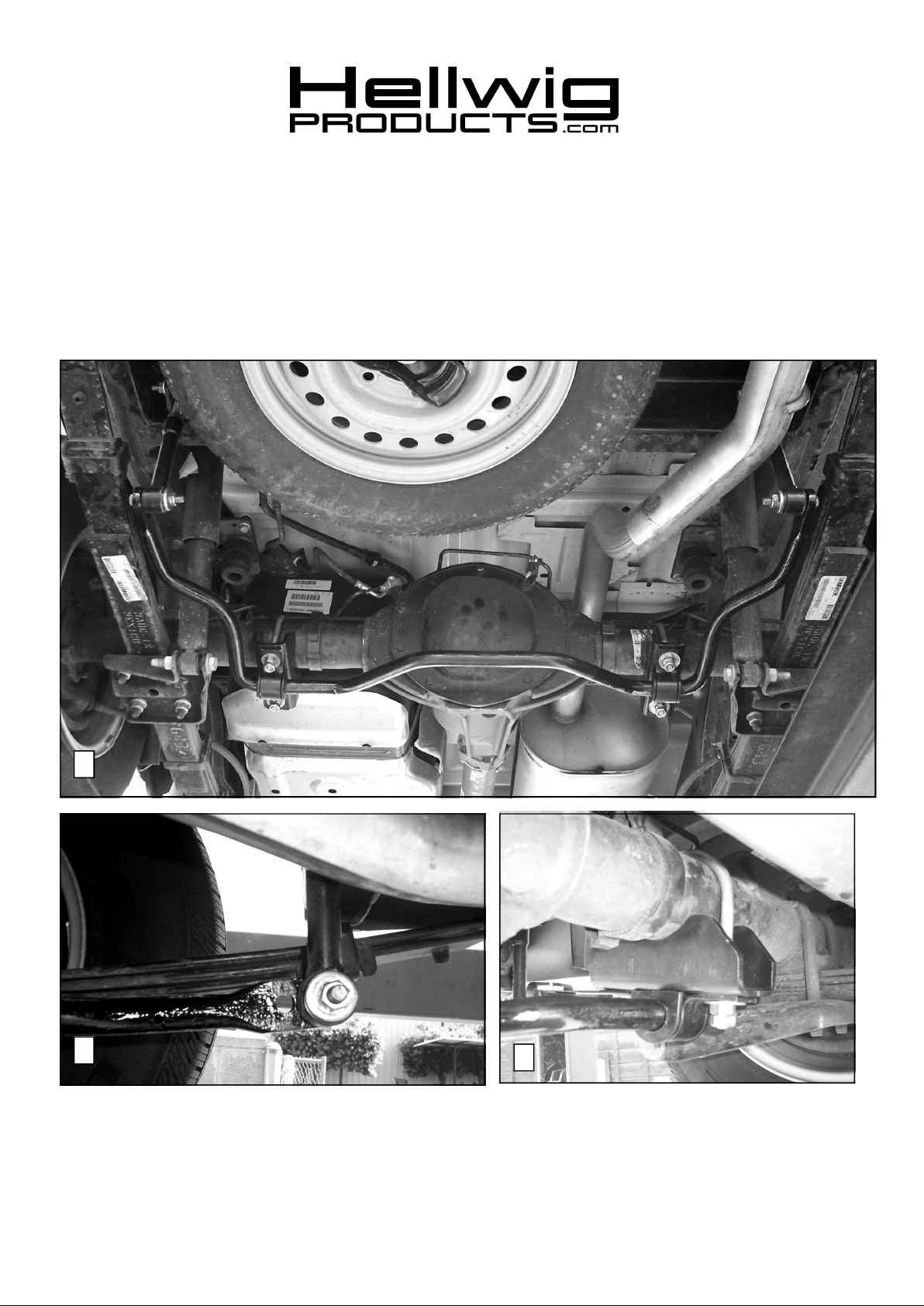
1. Lubricate the D-shaped poly-bushings and place onto the straight areas of the bar on each side of the center clearance hump
as shown in photo 1. Locate the bushings as close to the bend as possible to keep the bar from shifting side-to-side.
2. Place the U-bolts over the axle in the approximate position on the axle required to mount the bushings. Be sure to avoid
pinching brake lines, emergency brake cables, electrical harnesses, etc. with the installation of the U-bolt.
3. Install the U-bolt legs through the saddles and place the U-plates over the bushings on the bar. Mount the sway bar to the
axle using attached hardware. See Photo 3. Snug the nuts enough to hold the sway bar in position but loose enoughto
allow for adjustment later.
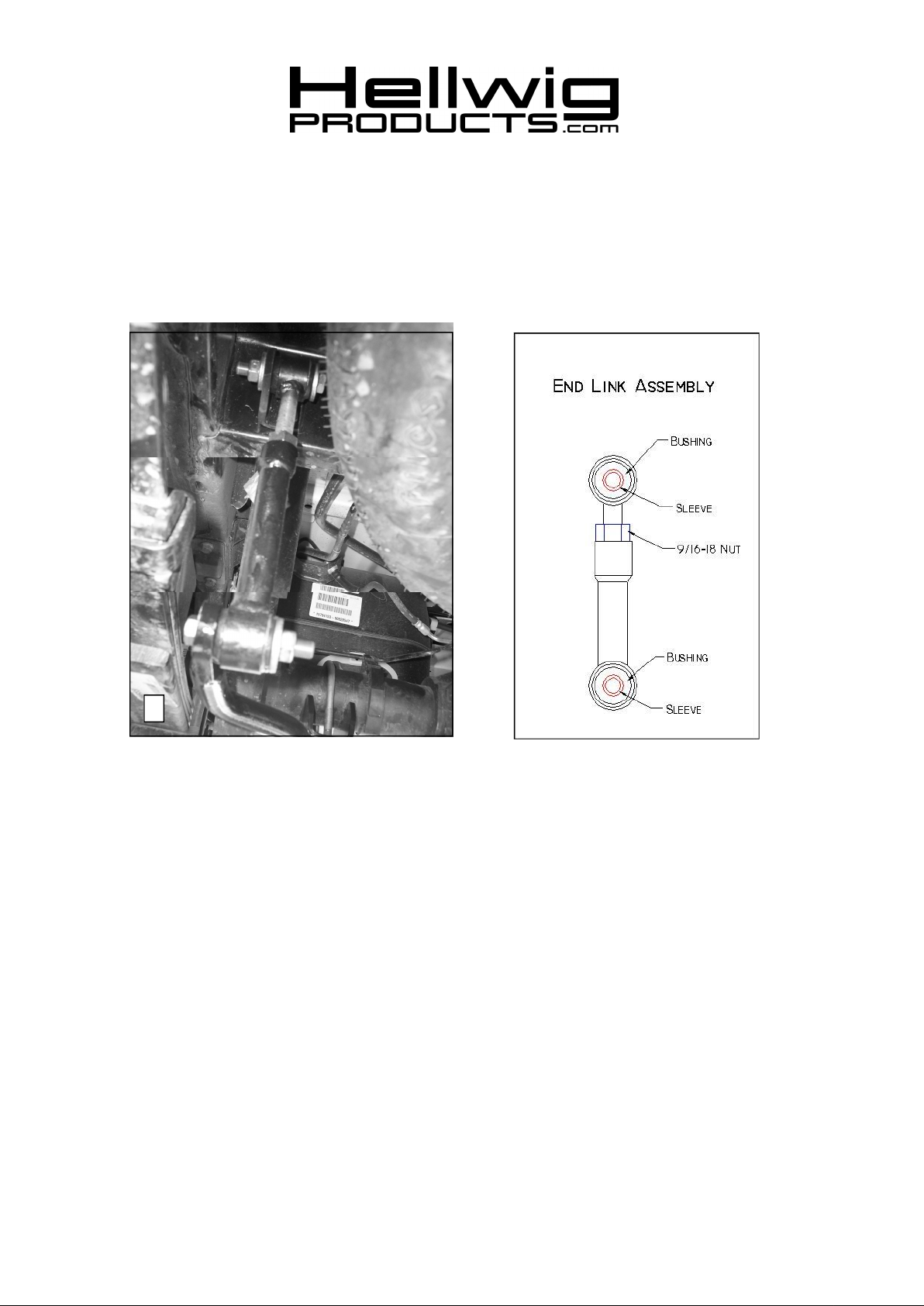
4. Assemble the end links as shown in diagram above. Lubricate the hourglass bushings and sleeves to aid installation.
5. Locate end links on sway bar as shown in Photo 2. Attach end links to sway bar using the 7/16 X 2-3/4 “ bolt and heavy
washer as shown in Photos 2&4.
7680 ( R-7680 ) 05/23/06

559-734-7451 800-367-5480 FAX 559-734-7460
5 6
6. Assemble the angle brackets to the end links as shown in Photos 4,5,&6. The angle brackets will attach to the wall of the
shock crossmember.
7. Align the sway bar and end links on the vehicle to match the photos. Make sure that the sway bar installation will not
interfere with any suspensionor exhaust components. The end links are adjustable to accommodate various ride height
and mounting preferences. When the end links and sway bar are properly aligned, locate and mark the holes for the angle
brackets.
8. Drill 13/32” holes for the angle brackets and mount angle brackets as shown in Photos 5&6 using the 3/8” bolts and hardware. It may be necessary to remove the spare tire and disconnect the exhaust pipe hanger for clearance while drilling
holes.
9. Torque all mounting hardware to spec. Double nut the axle U-bolts after tightening to spec.
10. Re-install spare tire and re-connect exhaust pipe hanger (if required).
11. The sway bar arms have two mounting holes. Mounting the sway bar on the outer hole is the nominal position. For firmer
settings, use the inner holes. We recommend starting with the outer mounting hole as in photo ( 2 ) until you are accustomed
to the vehicles new handling characteristics. Select the mounting point that best fits your driving style.
12. Bounce the vehicle checking for clearance on all undercarriage components shocks, exhaust etc… test drive the vehicle and
recheck your installation. Recheck periodically on a regular basis thereafter.
ATTENTION INSTALLER: BE SURE THE CUSTOMER RECEIVES THIS INSTRUCTION SHEET, ALLWARNING
AND NOTECARDS AND THE WARRANTY FORM.
7680 ( R-7680 ) 05/23/06
 Loading...