

Hellwig 55809 User Manual
559-734-7451 800-367-5480 FAX 559-734-7460
INSTALLATION INSTRUCTIONS
FRONT STABILIZER BAR
75-79 NOVA,VENTURA 70-81 CAMARO,FIREBIRD
73-77 EL CAMINO,SPRINT ( 64-72 A-BODY CARS )
SKYLARK, REGAL,CENTURY,CHEVELLE,MALIBU,
MONTE CARLOCUTLAS,LEMANS & GTO
Thank you for purchasing a quality HellwigProduct.
PLEASE READ THISINSTRUCTION SHEET COMPLETELY BEFORE STARTING YOUR INSTALLATION
1
2
3
54
5703 ( R-5703 ) 03/09/05

559-734-7451 800-367-5480 FAX 559-734-7460
TORQUE TABLE
BOLT SIZE: 3/8” = 20-30 ft. lbs. – 7/16” = 35-45 ft. lbs. – ½” = 50-70 ft. lbs. – 9/16” = 70-90 ft. lbs.
SAFETY: BEFORE STARTING YOUR INSTALLATION, BE SURE TO SET PARKING BRAKE AND
CHOCK TIRES.
NOTE: TO EASE INSTALLATION AND TO PROPERLY ADJUST THE SWAY BAR, THE WEIGHT
OF THE VEHICLE MUST BE ON THE SUSPENSION AS IF DRIVING DOWN THE ROAD.
DO NOT RAISE THE VEHICLE BY THE FRAME.
NOTE: THIS UNIT IS DESIGNED AS A REPLACEMENT FOR THE FACTORY INSTALLED FRONT
ANTI-SWAY BAR
NOTE: THIS KIT INCLUDES LOCK NUTS WHICH REQUIRE TIGHTENING WITH A WRENCH
AFTER BEING STARTED BY HAND.
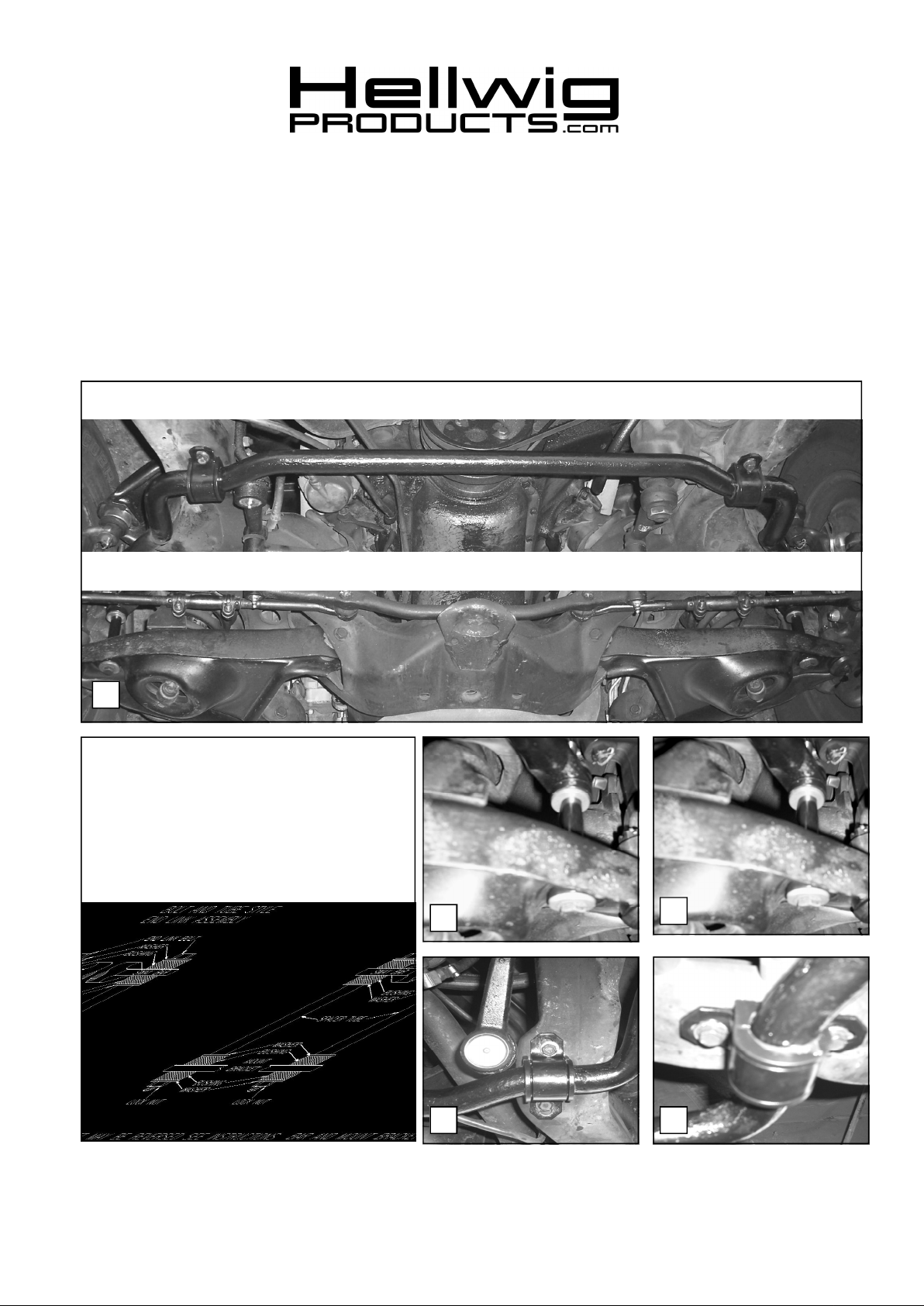
1. Remove the factory installed anti sway bar and the mounting hardware. Keep the U-plate mounting
bolts as these will be re-used to install the new front sway bar on your vehicle.
2. Install the D-shaped poly bushings on the new sway bar in the same location that the bushings were
on the factory sway bar. SEE PHOTO ONE (1).
3. Assemble the end link assemblies. ( SEE DIAGRAM). Install on the vehicle’s lower control arms.
( SEE PHOTOS 2 & 3 ).
4. Position the U-plates over the D-shaped poly bushings and position the new sway bar on the frame
with the mounting bolts that were removed in STEP ONE. Leave loose at this time to allow for
adjustment later. SEE PHOTOS (4 &5)
5. Install the end link assemblies through the coined ends of the anti sway bar. (SEE PHOTOS 2 & 3 ).
Tighten locknuts just enough so that the poly bushings start to bulge. Do not over tighten.
6. Tighten the frame bolts to the factory specifications. Be sure that all bolts are tightened to specifications. Re-check your installation, check for clearance on all undercarriage components; wiring, exhaust, springs, fuel and brake lines.
7. Turn wheels full lock left and then right, check for clearance on tires, wheels and steering components.
8. After one week of driving recheck your installation. Re-check on regular basis thereafter.
ATTENTION INSTALLER: BE SURE THAT THE CUSTOMER RECEIVES THIS INSTRUCTION
SHEET, ALL IMORTANT NOTE CARDS AND THE WARRANTY
FORM
5703 ( R-5703 ) 03/09/05
 Loading...