

Hellwig 55764 User Manual
559-734-7451 800-367-5480 FAX 559-734-7460
INSTALLATION INSTRUCTIONS
55809
GM A/G-BodyAdjustable Rear Sway Bar
Thank you for purchasing a quality Hellwig Product.
1
TORQUE TABLE
Bolt Size 3/8”— 35 ft lbs * Bolt Size 7/16”— 45 ft lbs* Bolt Size 1/2”—65 ft lbs *Bolt Size 9/16”— 90 ft lbs
SAFETY: BEFORE BEGINNING INSTALLATION BE SURE TO SET THE PARKING BRAKE AND
CHOCK THE FRONT WHEELS.
NOTE: TO PROPERLY ADJUST THE BAR, THE WEIGHT OF THE VEHICLE MUST BE ON THE SUSPENSION AS IF DRIVING DOWN THE ROAD.
NOTE: THIS KIT REQUIRES DRILLING THE FRAME RAIL AND POSSIBLE RELOCATION OF FUEL
AND BRAKE LINES. INSTALLER MUST ENSURE THAT THE SWAY BAR KIT WILL NOT INTERFERE WITH ANY FUEL OR BRAKE LINES OR HOSES.
IMPORTANT NOTE: SWAYBAR END LINKS MUST BE ATTACHED ON OUTER
HOLE PRIOR TO INITIAL USE.
55809(R-55809) 8/17/2010
559-734-7451 800-367-5480 FAX 559-734-7460
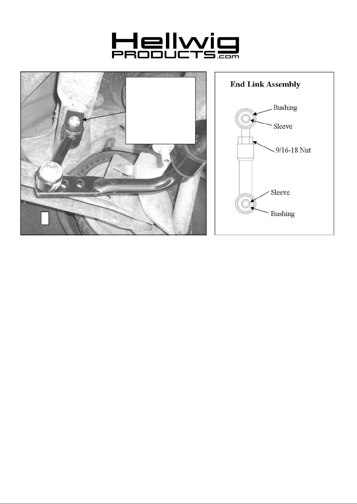
Install sway bar assembly
and mark location of
clevis. Drill
17/32” (.531”) hole in bottom flange of crossmember
to mount clevis. Attach
clevis with 1/2” fastener,
washer and locknut.
Torque to 50 ft-lb.
2
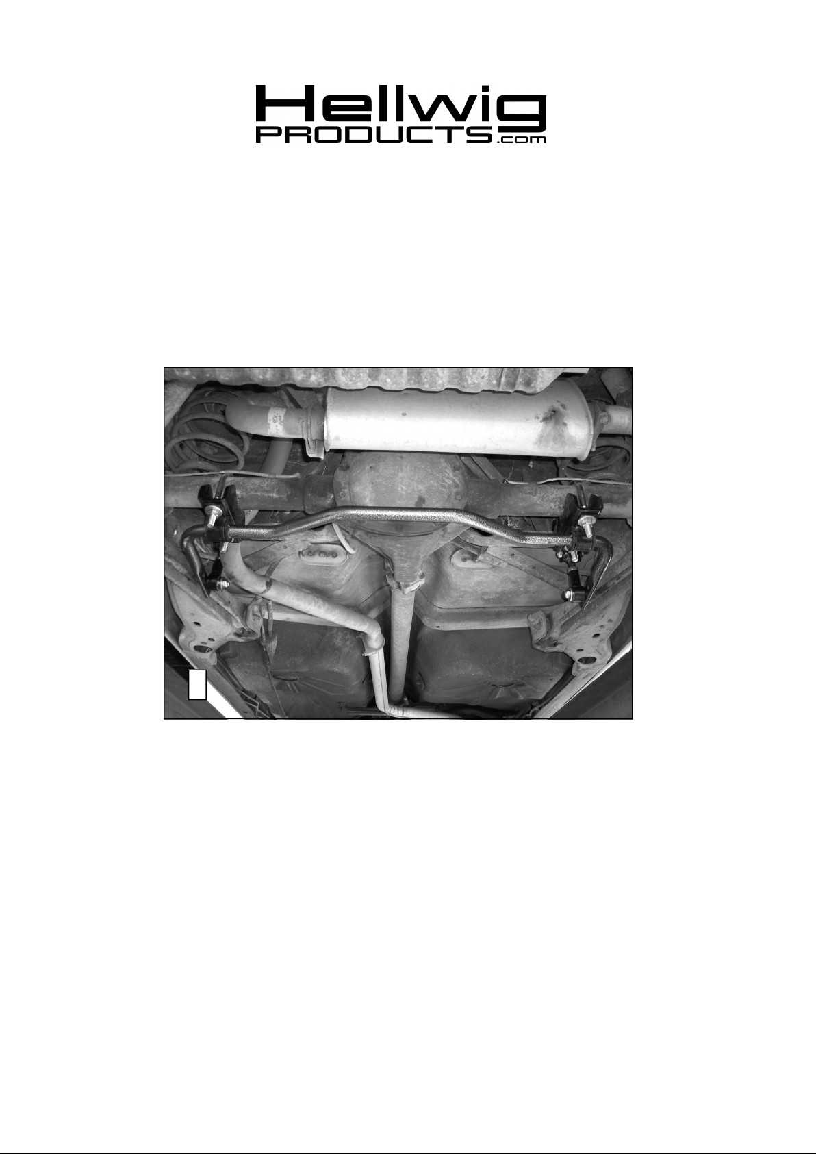
1. Lubricate the D shaped bushings and place them onto the straight areas of the bar on each side of the
center hump as close to the outside bend as possible. See photo (1).
2. Hold sway bar up to the axle and locate the position on the axle tubes to mount the u-bolts. Be sure to
put the U-Bolts Under Any Brake Lines, Wires or Hoses on the Axle to Avoid Any Possible
Damage. The threads of the U-Bolts will point down.
3. Place the saddle brackets onto the U-Bolts on the axle tubes. Place the U-Plates over the D shaped
bushings on the bar and attach the bar to the U-Bolts and saddle brackets with the flat washers and
Stover locknuts provided. LEAVE LOOSE AT THIS TIME to allow for adjustment later.
4. Position sway bar on axle so that it clears all frame mounted components including fuel tanks, brake
lines, fuel lines, exhaust pipes etc. Sway bar can be rotated back and forth on axle to maximize clearance.
5. Assemble end links as shown in diagram. Assemble end links by inserting bushings first and then inner sleeve into outer sleeve of end link. Fully lubricate bushings before installation. Install 9/16”
nut on threaded section of end link before assembling the two halves together as shown. IMPOR-
TANT NOTE - The end link threads are NOT powder coated so that the end links can be
threaded together. To prevent corrosion, it is advised to lightly coat the exposed threads with
black spray paint after adjusting to desired length.
6. Attach end links to the center hole of the sway bar using 7/16” X 2-1/2” bolts and locknuts. This position is for locating the clevis on the crossmember only. Before driving vehicle, attach the end links to
the outermost hole.
7. Attach end links to clevis using 7/16 X 2-1/4” bolts and locknuts. Leave loose for adjustment later.
8. Mark location of clevis on the frame and drill a 17/32” (.531”) hole in the bottom flange of the crossmember. BEFORE DRILLING ANY HOLES IN THE FRAME—RELOCATE AND/OR PRO-
TECT ANY FUEL OR BRAKE LINES THAT MAY INTERFERE WITH THE DRILL BIT OR
55809(R-55809) 8/17/2010
 Loading...