

Hellwig 55705 User Manual
559-734-7451 800-367-5480 FAX 559-734-7460
INSTALLA TION INSTRUCTIONS
FRONT STABILIZER BAR
67-69 GM F-Body
Thank you for purchasing a quality Hellwig Product.
PLEASE READ THIS INSTRUCTION SHEET COMPLETELY BEFORE STARTING YOUR INSTALLATION
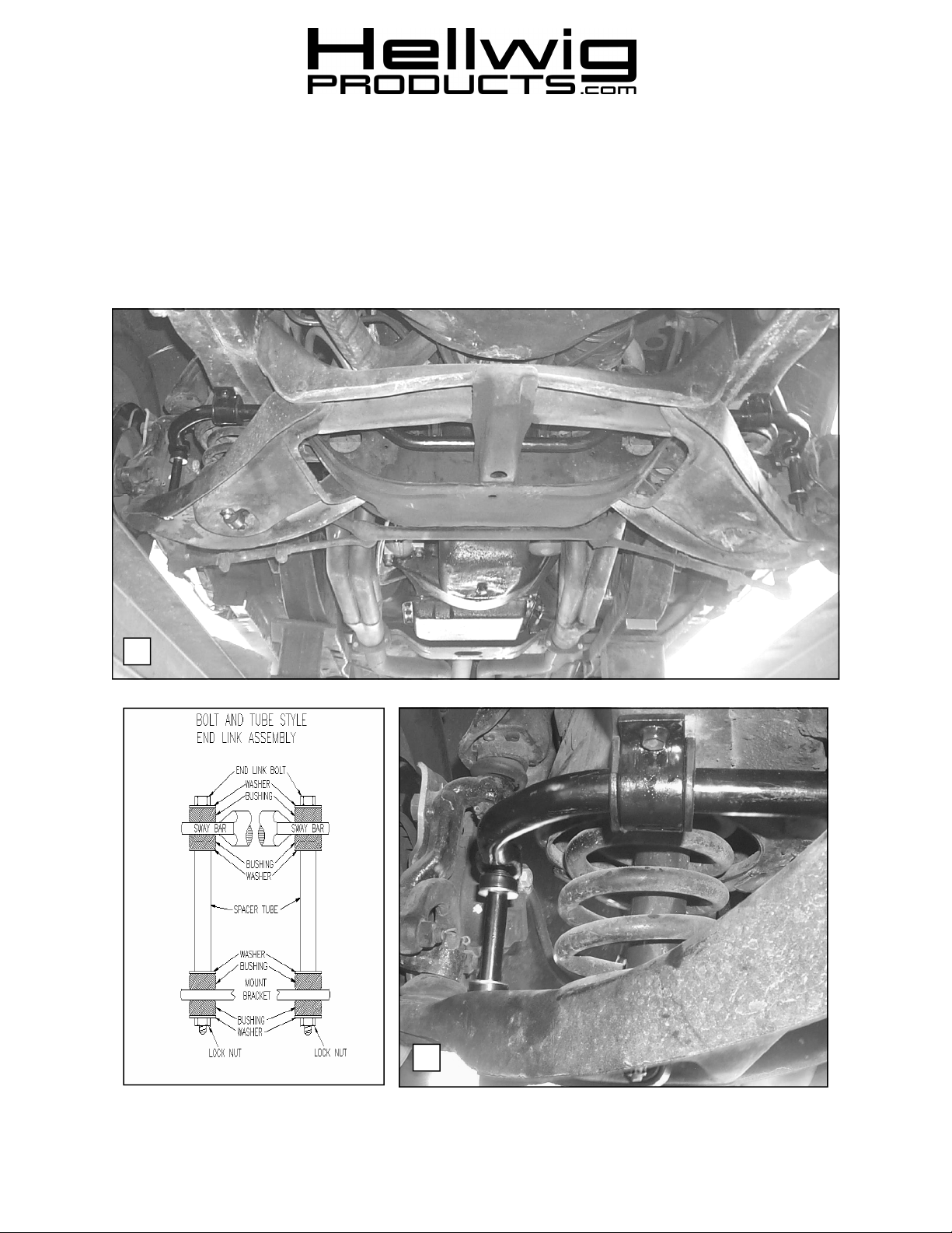
1
2
5705 ( R-5705 ) 03/09/05

559-734-7451 800-367-5480 FAX 559-734-7460
TORQUE TABLE
BOLT SIZE: 3/8” = 20 -30 ft. lbs. – 7/16” = 35-45 ft. lbs. – ½” = 50-70 ft. lbs. – 9/16” = 70-90 ft. lbs.
SAFETY: BEFORE STARTING YOUR INSTALLATION, BE SURE TO SET PARKING BRAKE AND
CHOCK TIRES.
NOTE: THIS UNIT IS DESIGNED AS A REPLACEMENT FOR THE FACTORY INSTALLED FRONT
ANTI-SWAY BAR
NOTE: THIS KIT INCLUDES LOCK NUTS WHICH REQUIRE TIGHTENING WITH A WRENCH
AFTER BEING STARTED BY HAND.
1. Raise vehicle and place on jack stands. Make sure vehicle is secure and stable before proceeding to next step.
2. Remove driver’s side front wheel.
3. Disconnect factory sway bar from vehicle and remove sway bar by pulling it out of subframe through driver’s
side. It may be necessary to rotate sway bar back and forth to clear components while removing sway bar
from vehicle.
4. Insert new sway bar from driver’s side through subfra me until oriented as shown in photo (1).
5. Lubricate D-bushings and place on sway bar as shown in photo 1.
6. Attach U-plates to frame as shown in photo (2) using factory hardware.
7. Attach end links as shown in photo (2)
8. Tighten end links until bushings begin to bulge slightly.
9. Tighten frame bolts to factory specification.
10. Bounce vehicle a couple of times and check installation for cleara nce to fuel and brake lines and other components. After one week of driving recheck your installation and fastener torque. Recheck on a regular basis
thereafter.
ATTENTION INSTALLER: BE SURE THAT THE CUSTOMER RECEIVES THIS INSTRUCTION
SHEET, ALL IMORTANT NOTE CARDS AND THE WARRANTY
FORM
5705 ( R-5705 ) 03/09/05
 Loading...