


Installers Guide
|
Guide d’installation |
|
Model/Modèles: |
Underwriters Laboratories Listed |
Vienna I and II |
Homologuée Underwriters Laboratories |
|
|
|
|
|
|
|
|
|
|
|
|
|
|
WARNING: If the information in these |
|
|
|
|
|
AVERTISSEMENT: Assurez-vous de |
|
|||
|
instructions is not followed exactly, a |
|
|
|
|
|
bien suivre les instructions données |
|
|||
|
|
|
|
|
|
dans cette notice pour réduire au mini- |
|
||||
|
fire or explosion may result causing |
|
|
|
|
|
|
||||
|
|
|
|
|
|
mum le risque d’incendie ou d’explosion |
|
||||
|
property damage, personal injury or |
|
|
|
|
|
|
||||
|
|
|
|
|
|
ou pour éviter tout dommage matériel, |
|
||||
|
death. |
|
|
|
|
|
toute blessure ou la mort. |
|
|||
|
|
|
|
|
|
– Ne pas entreposer ni utiliser d’essence |
|||||
- Do not store or use gasoline or other |
|
|
|
||||||||
|
|
|
|
ni d’autres vapeurs ou liquides |
|||||||
|
flammable vapors and liquids in the vi- |
|
|
|
|
inflammables dans le voisinage de cet |
|||||
|
cinity of this or any other appliance. |
|
|
|
|
appareil ou de tout autre appareil. |
|||||
- WHAT TO DO IF YOU SMELL GAS: |
|
|
|
– QUE FAIRE SI VOUS SENTEZ UNE |
|||||||
|
|
|
|
ODEUR DE GAZ |
|||||||
|
• Do not try to light any appliance. |
|
|
|
|
• Ne tentez pas d’allumer d’appareil. |
|||||
|
• Do not touch any electrical switch. |
|
|
|
|
• Ne touchez à aucun interrupteur. Ne |
|||||
|
|
|
|
|
|
pas vous servir des téléphones se |
|||||
|
• Do not use any phone in your |
|
|
|
|
|
trouvant dans le bâtiment où vous |
||||
|
|
|
|
|
|
vous trouvez. |
|||||
|
building. |
|
|
|
|
|
|||||
|
|
|
|
|
• |
Évacuez la pièce, le bâtiment ou la |
|||||
|
|
|
|
|
|
|
|||||
|
• Immediately call your gas supplier |
|
|
|
|
|
zone. |
||||
|
from a neighbor's phone. Follow the |
|
|
|
|
• |
Appelez immédiatement votre |
||||
|
gas supplier's instructions. |
|
|
|
|
|
fournisseur de gaz depuis un voisin. |
||||
|
• If you cannot reach your gas sup- |
|
|
|
|
|
Suivez les instructions du fournisseur. |
||||
|
|
|
|
|
• |
Si vous ne pouvez rejoindre le |
|||||
|
plier, call the fire department. |
|
|
|
|
|
fournisseur de gaz, appelez le service |
||||
- Installation and service must be |
|
|
|
|
|
des incendies. |
|||||
|
|
|
– L’installation et l’entretien doivent être |
||||||||
|
performed by a qualified installer, |
|
|
|
|||||||
|
|
|
|
|
assurés par un installateur ou un service |
||||||
|
service agency, or the gas supplier. |
|
|
|
|
d’entretien qualifié ou par le fournisseur |
|||||
|
|
|
|
|
|
|
de gaz. |
||||
|
|
|
|||||||||
1. This appliance may be installed in an after- |
|
|
|
1. Cet appareil peut être utilisé dans un mobile |
|||||||
|
market, permanently located, manufactured |
|
|
|
home, installé à demeure si les règlements |
||||||
|
(mobile) home, where not prohibited by lo- |
|
|
|
|
locaux le permettent. |
|||||
|
|
|
2. Cet appareil ne peut être utilisé qu’avec le |
||||||||
|
cal codes. |
|
|
||||||||
2. This appliance is only for use with the type |
|
|
|
|
type de gaz spécifié sur la plaque de |
||||||
|
|
|
caractéristiques. Il n’est pas convertible et |
||||||||
|
of gas indicated on the rating plate. This |
|
|
|
|
||||||
|
|
|
|
ne peut pas fonctionner avec d’autres gaz |
|||||||
|
appliance is not convertible for use with |
|
|
|
|
||||||
|
|
|
|
que celui indiqué, à moins qu’un ensemble |
|||||||
|
other gases, unless a certified kit is used. |
|
|
|
homologué ne soit utilisé. |
||||||
|
|
|
|
|
|
|
|
|
|
|
|
|
|
|
1 |
|
|
|
|
|
585-900EFD 10/01 |
||
|
|
|
|
|
|
|
|
|
|
|
|
WARNING: Improper installation, adjustment, alteration, service or maintenance can cause injury or property damage. Refer to this manual.
For assistance or additional information consult a qualified installer, service agency or the gas supplier.
Read this manual before installing or operating this appliance. This Installers Guide must be left with appliance for future reference.
! |
SAFETY AND WARNING |
INFORMATION |
!READ and UNDERSTAND all instructions carefully before starting the installation. FAILURE TO FOLLOW these installation instructions may result in a possible fire hazard and will void the warranty.
!Prior to the first firing of the fireplace, READ the Using Your Fireplace section of the Owners Guide.
!DO NOT USE this appliance if any part has been under water. Immediately CALL a qualified service technician to inspect the unit and to replace any part of the control system and any gas control which has been under water.
!THIS UNIT IS NOT FOR USE WITH SOLID FUEL.
Installation and repair should be PERFORMED
!by a qualified service person. The appliance and venting system should be INSPECTED before initial use and at least annually by a professional service person. More frequent cleaning may be required due to excessive lint from carpeting, bedding material, etc. It is IMPERATIVE that the unit’s control compartment, burners, and circulating air passageways BE KEPT CLEAN to provide for adequate combustion and ventilation air.
Always KEEP the appliance clear and free from
!combustible materials, gasoline, and other flammable vapors and liquids.
AVERTISSEMENT: Une installation, un réglage, une modification, un entretien ou une maintenance incorrects peuvent entraîner des blessures ou dommages matériels. Consulter le manuel.
Pour toute assistance ou pour obtenir de plus amples informations, consulter un installateur qualifié, un service aprèsvente ou le fournisseur de gaz.
Lire ce manuel avant d’installer ou de fairé fonctionner cet appareil. Ranger ce Guide D’installation à proximité de l’appareil pour pouvoir le consulter en cas de besoin.
!CONSIGNES DE SÉCURITÉ
!LIRE ATTENTIVEMENT et bien COMPRENDRE toutes les instructions avant d’entreprendre l’installation. LE NON-RESPECT DE CES instructions d’installation peut provoquer un incendie et annule la garantie.
!Avant le premier allumage de la cheminée, LIRE LA SECTION Fonctionnement de la cheminée dans le manuel de l’utilisateur.
!NE PAS SE SERVIR de cet appareil s’il a été plongé dans l’eau, complètement ou en partie. APPELER un technicien qualifié pour inspecter l’appareil et remplacer toute partie du système de contrôle et toute commande qui ont été plongées dans l’eau.
!CET APPAREIL NE PEUT PAS ÊTRE UTILISÉ AVEC DU COMBUSTIBLE SOLIDE.
FAIRE EFFECTUER l’installation et la réparation
!de l’appareil par un technicien après-vente qualifié. Faire INSPECTER l’appareil et la ventilation avant la première utilisation, et les faire nettoyer ensuite au moins une fois par an par une personne qualifiée. Effectuer le nettoyage plus fréquemment si des tapis, de la literie, etc..., produisent des peluches en quantité excessive. Il est IMPÉRATIF que le compartiment des réglages de l’appareil, les brûleurs et le système de ventilation SOIENT TOUJOURS PROPRES pour assurer un volume suffisant d’air de combustion et de ventilation.
!Veiller à NE JAMAIS laisser de matériaux inflammables à proximité de l’appareil.
2
|
! |
NEVER OBSTRUCT the flow of combustion and |
|
ventilation air. Keep the front of the appliance CLEAR |
|
|
|
of all obstacles and materials for servicing and proper |
|
|
operations. |
|
! |
Due to the high temperature, the appliance should be |
|
|
LOCATED out of traffic areas and away from furniture |
|
|
and draperies. Clothing or flammable material |
|
|
SHOULD NOT BE PLACED on or near the appliance. |
|
|
|
|
! |
Children and adults should be ALERTED to the |
|
hazards of high surface temperature and should STAY |
|
|
|
AWAY to avoid burns or clothing ignition. Young |
|
|
children should be CAREFULLY SUPERVISED when |
|
|
they are in the same room as the appliance. |
|
|
|
|
! |
These units MUST use one of the vent systems |
|
|
described in the Installing the Fireplace section of the |
|
|
Installers Guide. NO OTHER vent systems or |
|
|
components MAY BE USED. |
|
|
|
|
! |
This gas fireplace and vent assembly MUST be vented |
|
|
directly to the outside and MUST NEVER be attached |
|
|
to a chimney serving a separate solid fuel burning |
|
|
appliance. Each gas appliance MUST USE a separate |
|
|
vent system. Common vent systems are PROHIBITED. |
|
|
|
|
! |
INSPECT the external vent cap on a regular basis to |
|
|
make sure that no debris is interfering with the air |
|
|
flow. |
|
|
|
|
! |
The glass door assembly MUST be in place and |
|
|
sealed, and the trim door assembly MUST be in place |
|
|
on the fireplace before the unit can be placed into |
|
|
safe operation. |
|
|
|
|
! |
DO NOT OPERATE this appliance with the glass door |
|
|
removed, cracked, or broken. Replacement of the |
|
|
glass door should be performed by a licensed or |
|
|
qualified service person. DO NOT strike or slam the |
|
|
glass door. |
|
|
|
|
! |
The glass door assembly SHALL ONLY be replaced |
|
|
as a complete unit, as supplied by the gas fireplace |
|
|
manufacturer. NO SUBSTITUTE material may be used. |
|
|
|
|
! |
DO NOT USE abrasive cleaners on the glass door |
|
|
assembly. DO NOT ATTEMPT to clean the glass door |
|
|
when it is hot. |
|
|
|
|
! |
Turn off the gas before servicing this appliance. It is |
|
|
recommended that a qualified service technician |
|
|
perform an appliance check-up at the beginning of |
|
|
each heating season. |
|
|
|
|
! |
Any safety screen or guard removed for servicing must |
|
|
be replaced before operating this appliance. |
|
|
|
! |
! |
DO NOT place furniture or any other combustible |
|
household objects within 36 inches of the fireplace |
|
|
|
front. |
|
|
|
NE PAS OBSTRUER le débit de l’air de combustion ou
!d’échappement. Veiller à ce que le devant de l’appareil soit toujours DÉGAGÉ de tout obstacle pour permettre l’entretien et assurer un fonctionnement correct.
!Etant donné sa température élevée, installer l’appareil À L’ÉCART des zones de passage, des meubles et des rideaux. Ne laisser en aucun cas des vêtements ou des matériaux inflammables SUR OU À PROXIMITÉ de l’appareil.
INSISTER auprès des enfants et des adultes sur les ! dangers que présentent des surfaces portées à haute température et les inciter à RESTER À L’ÉCART pour éviter tout risque de brûlure ou de voir des vêtements prendre feu. Les enfants en bas âge doivent être
SURVEILLÉS ATTENTIVEMENT quand ils se trouvent dans la pièce où l’appareil est installé.
L’appareil DOIT être pourvu d’un des systèmes de ! ventilation décrits dans la section «Installation de la cheminée» de ce Manuel d’installation. N’UTILISER AUCUN AUTRE système de ventilation ou composant.
Cette cheminée au gaz et son système de ventilation ! DOIVENT communiquer directement avec l’air extérieur et ils NE DOIVENT JAMAIS être raccordés à une cheminée desservant un appareil séparé brûlant des combustibles solides. Chaque appareil fonctionnant au gaz DOIT DISPOSER d’un système de ventilation séparé. Les systèmes de ventilation communs à
plusieurs appareils sont INTERDITS.
INSPECTER régulièrement la mitre du système de ! ventilation et s’assurer qu’elle ne contient pas
d’obstacles à la circulation de l’air.
La porte en verre DOIT être en place, ainsi que son ! encadrement, pour que la cheminée puisse fonctionner
en toute sécurité.
NE PAS FAIRE FONCTIONNER cet appareil si la porte
! en verre a été déposée ou si elle est fêlée ou cassée. Faire effectuer le remplacement de la porte en verre par un technicien après-vente qualifié. NE PAS cogner ou fermer violemment la porte en verre.
Ne remplacer la porte en verre que comme un tout, ! dans l’état où elle est livrée par le fabricant. Ne pas
utiliser de SUBSTITUT.
! NE PAS EMPLOYER de produits d’entretien abrasifs sur la porte en verre. NE PAS ESSAYER de nettoyer la porte en verre quand elle est chaude.
! Couper l’alimentation en gaz avant toute opération d’entretien sur cet appareil. Nous recommandons un examen de l’appareil par un technicien après-vente qualifié au début de chaque saison de chauffage.
Tout dispositif de sécurité ou garant déposé pour ! l’entretien doit être reposé avant l’utilisation de
l’appareil.
! |
NE placez NI meubles, NI autres objets ménagers |
! |
|
||
combustibles à moins de 91,44 cm (36 pouces) de la |
|
|
|
façadedufoyer. |
|
3

Table of Contents |
|
|
!Safety and Warning Information ............................... |
2 |
|
!Service Parts List ........................................................ |
5 |
|
Section 1: Approvals and Codes ............................... |
9 |
|
Approval Listing and Codes ........................................... |
9 |
|
Appliance Certification ................................................... |
9 |
|
Installation Codes .......................................................... |
9 |
|
High Altitude Installations ............................................ |
10 |
|
Section 2: Getting Started ....................................... |
11 |
|
Introducing the Heat-N-Glo Direct Vent Gas Stoves ..... |
11 |
|
Pre-installation Preparation ......................................... |
11 |
|
Section 3: Installing the Stove................................. |
14 |
|
! Step 1 |
Locating the Stove .......................................... |
14 |
Step 2 |
Installing the Vent System............................. |
16 |
!A. Vent System Approvals ............................. |
16 |
|
! B. Installing Vent Components ....................... |
24 |
|
! C. Vent Termination ........................................ |
29 |
|
Step 3 |
The Gas Control System ................................ |
33 |
! Step 4 |
The Gas Supply Line ...................................... |
34 |
Step 5 |
Gas Pressure Requirements .......................... |
35 |
Step 6 |
Wiring the Stove ............................................. |
36 |
Step 7 |
Finishing ........................................................ |
39 |
Step 8 |
Installing Logs and Ember Material ................. |
40 |
|
Positioning the Logs ....................................... |
40 |
|
Placing the Ember Material ............................ |
40 |
! Step 9 |
Before Lighting the Stove ................................ |
41 |
Step 10 Lighting the Stove ........................................... |
41 |
|
|
After the Installation ....................................... |
41 |
! Section 4: Maintaining and Servicing |
|
|
|
Your Stove ............................................... |
42 |
!= Contains updated information.
Table des matières |
|
! Consignes de sécurité ................................................ |
2 |
! Liste des pièces de rechange ................................... |
5 |
Section 1: Homologations et codes d’installation ... |
9 |
Homologation et codes.................................................. |
9 |
Certifications .............................................................. |
9 |
Codes d’installation ....................................................... |
9 |
Installations à haute altitude ......................................... |
10 |
Section 2: Mise en marche ...................................... |
11 |
Présentation des appareils de chauffage |
|
Heat-N-Glo à ventilation directe .................................... |
11 |
Avant l’installation ........................................................ |
11 |
Section 3: Installation .............................................. |
14 |
! Étape 1 Emplacement ................................................. |
14 |
Étape 2 Installation du système de ventilation ............. |
16 |
!A. Homologations du système de ventilation .... |
16 |
!B. Pose des éléments de ventilation .............. |
24 |
! C. Mitres ........................................................ |
29 |
Étape 3 Commandes d’alimentation en gaz ................. |
33 |
! Étape 4 Raccordement au gaz .................................... |
34 |
Étape 5 Spécifications relatives à la pression du gaz ..... |
35 |
Étape 6 Câblage .......................................................... |
36 |
Étape 7 Finitions ......................................................... |
39 |
Étape 8 Pose des bûches et des braises .................... |
40 |
Positionnement des bûches ........................... |
40 |
Pose des braises ........................................... |
40 |
! Étape 9 Avant l’allumage ............................................. |
41 |
Étape 10 Allumage ...................................................... |
41 |
Après l’installation ........................................................ |
41 |
! Section 4: Entretien et révision ............................... |
42 |
! = Contient des informations mises à jour.
4
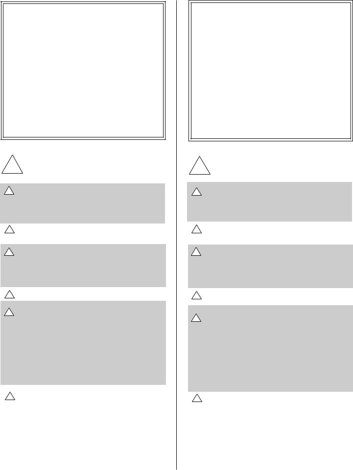
Service Parts
VIENNA I (NG, LP) Exploded Parts Diagram / VIENNA I (GN, PL) Vue éclatée des pièces
13 |
* Part number list on following page. |
|
* La liste des numéros de pièce se |
|
trouve à la page suivante. |
|
14 |
3
7
2
16
22 |
|
17 |
|
|
|
|
|
15 |
|
18 |
|
|
|
|
|
19 |
|
8 Log Set Assembly |
|
6 |
|
|
|
5 |
20 |
21 |
9 |
|
1 |
|
|
4 |
|
10 |
12 |
|
|
11 |
|
|
|
|
5
VIENNA I (NG, LP) Service Parts List / VIENNA I (GN, PL) Liste des pièces de rechange
IMPORTANT: THIS IS DATED INFORMATION. The most current information is located on your dealers VIP site. When ordering, supply serial and model numbers to ensure correct service parts. / IMPORTANT : L'information fournie dans cette brochure n'est valide que pendant une courte période. Les sites VIP des distributeurs disposent des renseignements les plus récents. Lors d'une commande, veuillez fournir les numéros de série et de modèles pour un remplacement adéquat des pièces.
ITEM / |
|
|
|
|
STANDING PILOT IGNITION / D’ALLUMAGE PAR VEILLEUSE |
SERIAL # / |
PART NUMBER |
|||||||
PIÈCE |
|
|
|
|
N° DE SÉRIE |
/ N° DE PIÈCE |
||||||||
|
|
|
|
|
|
|
|
|
|
|
|
|||
|
|
|
|
|
|
|
|
|
||||||
|
Sit Valve |
/ |
Sit Vanne |
|
|
|
|
|
||||||
|
|
|
|
|
|
|
|
|
||||||
1 |
Valve NG |
/ |
Valve GN |
|
|
|
|
571-500 |
||||||
|
|
|
|
|
|
|
|
|
|
|||||
1 |
Valve LP |
/ |
Valve PL |
|
|
|
|
|
571-501 |
|||||
|
|
|
|
|
||||||||||
|
Pilot Assembly NG / |
Module de veilleuse GN |
|
571-510A |
||||||||||
|
|
|
|
|
|
|||||||||
|
Pilot Assembly LP |
/ |
Module de veilleuse PL |
|
571-511A |
|||||||||
|
|
|
|
|
|
|||||||||
|
Pilot Orifice NG |
/ |
Orifice de veilleuse GN |
|
571-516 |
|||||||||
|
|
|
|
|
|
|
||||||||
|
Pilot Orifice LP |
|
/ |
Orifice de veilleuse PL |
|
571-517 |
||||||||
|
|
|
|
|
|
|||||||||
|
Thermocouple |
/ |
Thermocouple |
|
571-511 |
|||||||||
|
|
|
|
|
|
|
|
|||||||
|
Thermopile |
/ |
Thermopile |
|
|
|
060-512 |
|||||||
|
|
|
|
|
|
|||||||||
2 |
ON/OFF Rocker Switch |
/ |
Interrupteur à bascule marche/arrêt |
|
060-525A |
|||||||||
|
|
|
|
|
|
|||||||||
3 |
Glass Door Assembly |
/ |
Module de Porte en verre |
|
GLA-V2 |
|||||||||
|
|
|
|
|
|
|
|
|
|
|
|
|
|
|
|
Bolt Bag |
|
|
|
|
|
|
|
|
|
|
|
SRV585-800 |
|
|
|
|
|
|
|
|
||||||||
4 |
Piezo Ignitor |
/ |
|
Allumage Piézo |
|
418-513 |
||||||||
|
|
|
|
|
|
|||||||||
|
Junction Box |
/ |
Boîtier de raccordement |
|
040-250A |
|||||||||
|
|
|
|
|
|
|
||||||||
5 |
Burner Tube |
|
/ |
Tube de brûleur |
|
477-301A |
||||||||
|
|
|
|
|
|
|||||||||
6 |
Burner Orifice NG (#38A) |
/ |
Orifice de brûleur GN (#38A) |
|
057-800 |
|||||||||
|
|
|
|
|
|
|||||||||
6 |
Burner Orifice LP (#53A) |
/ |
Orifice de brûleur PL (#53A) |
|
060-801 |
|||||||||
|
|
|
|
|
||||||||||
7 |
Burner NG, LP |
/ Brûleur GN, PL |
|
SRV585-325A |
||||||||||
8 |
Log Set Assembly / Jeu de Bûches |
|
LOGS-TOWN1 |
|||||||||||
|
|
|
|
|
|
|
|
|
|
|||||
9 |
Log 1 |
/ Bûche 1 |
|
|
|
|
|
|
SRV419-705 |
|||||
|
|
|
|
|
|
|
|
|
|
|||||
10 |
Log 2 |
/ Bûche 2 |
|
|
|
|
|
|
SRV446-703 |
|||||
|
|
|
|
|
|
|
|
|
|
|||||
11 |
Log 3 |
/ Bûche 3 |
|
|
|
|
|
|
SRV446-714 |
|||||
|
|
|
|
|
|
|
|
|
|
|||||
12 |
Log 4 |
/ Bûche 4 |
|
|
|
|
|
|
SRV446-715 |
|||||
|
|
|
|
|
|
|
||||||||
|
CAST STOVE PARTS |
|
|
|
|
|
||||||||
13 |
Top Grill Plate - Black |
|
|
|
|
SRV585-331BK |
||||||||
|
|
|
|
|
|
|
|
|
|
|
|
|
|
|
14 |
Top Plate |
|
|
|
|
|
|
|
|
|
|
|
SRV585-332* |
|
|
|
|
|
|
|
|
|
|
|
|
|
|
||
15 |
Front Plate |
|
|
|
|
|
|
|
|
|
|
SRV585-336* |
||
|
|
|
|
|
|
|
|
|
|
|
||||
16 |
Left Side Plate |
|
|
|
|
|
|
|
|
SRV585-337* |
||||
|
|
|
|
|
|
|
|
|
|
|||||
17 |
Right Side Plate |
|
|
|
|
|
|
|
SRV585-338* |
|||||
|
|
|
|
|
|
|
|
|
|
|
|
|
||
18 |
Base Plate |
|
|
|
|
|
|
|
|
|
|
SRV585-339* |
||
|
|
|
|
|
|
|
|
|
|
|
|
|
||
19 |
Ashlip Plate |
|
|
|
|
|
|
|
|
|
|
SRV585-340* |
||
|
|
|
|
|
|
|
|
|
|
|
|
|
|
|
20 |
Skirt Plate |
|
|
|
|
|
|
|
|
|
|
|
SRV585-341* |
|
|
|
|
|
|
|
|
|
|
|
|
|
|
|
|
21 |
Legs |
|
|
|
|
|
|
|
|
|
|
|
|
SRV585-342* |
|
|
|
|
|
|
|
|
|
|
|
||||
22 |
Vienna Handle |
|
|
|
|
|
|
|
|
585-Handle |
||||
|
|
|
|
|
|
|
|
|
|
|
|
|
|
|
|
|
|
|
|
|
|
|
|
|
|
|
* Color Code: BK, RED, GR, AL, EBK |
|
|
|
|
|
|
|
|
|
|
|
|
|
|
|
|
|
6

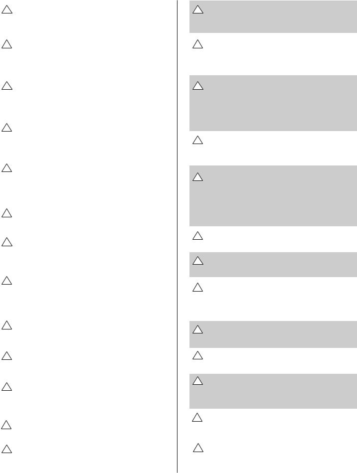
Service Parts
VIENNA II (NG, LP) Exploded Parts Diagram / VIENNA II (GN, PL) Vue éclatée des pièces
11
12
3 |
2 |
4


|
1 |
|
|
|
|
20 |
14 |
15 |
|
|
|
|
|
|
|
||
|
|
|
|
|
|
|
|
|
|
5 Log Set Assembly |
|
13 |
|
|
|
9 |
10 |
|
|
|
6 |
||
|
|
|
|
||
|
|
|
|
7 |
8 |
16 |
|
|
|
|
|
17 |
18 |
19 |
|
Part number list on following page. |
|
* La liste des numéros de pièce se trouve |
|||||
|
|
|
* |
à la page suivante. |
|
|
|
7 |
|
|
|
VIENNA II (NG, LP) Service Parts List / VIENNA II (GN, PL) Liste des pièces de rechange
IMPORTANT: THIS IS DATED INFORMATION. The most current information is located on your dealers VIP site. When ordering, supply serial and model numbers to ensure correct service parts. / IMPORTANT : L'information fournie dans cette brochure n'est valide que pendant une courte période. Les sites VIP des distributeurs disposent des renseignements les plus récents. Lors d'une commande, veuillez fournir les numéros de série et de modèles pour un remplacement adéquat des pièces.
ITEM / |
|
|
STANDING PILOT IGNITION / D’ALLUMAGE PAR VEILLEUSE |
SERIAL # / |
PART NUMBER |
|||||||
PIÈCE |
|
|
N°DE SÉRIE |
/ N° DE PIÈCE |
||||||||
|
|
|
|
|
|
|
|
|
|
|||
|
|
|
|
|
|
|
||||||
|
Sit Valve / Sit Vanne |
|
|
|
|
|
||||||
1 |
Valve NG / Valve GN |
|
|
|
|
571-500 |
||||||
1 |
Valve LP / Valve PL |
|
|
|
|
|
571-501 |
|||||
|
Pilot Assembly NG / |
Module de veilleuse GN |
|
571-510A |
||||||||
|
Pilot Assembly LP |
/ |
Module de veilleuse PL |
|
571-511A |
|||||||
|
Pilot Orifice NG |
/ |
Orifice de veilleuse GN |
|
571-516 |
|||||||
|
|
|
|
|
|
|
||||||
|
Pilot Orifice LP |
|
/ |
Orifice de veilleuse PL |
|
571-517 |
||||||
|
Thermocouple |
/ |
Thermocouple |
|
571-511 |
|||||||
|
|
|
|
|
|
|
||||||
|
Thermopile / |
Thermopile |
|
|
|
060-512 |
||||||
|
|
|
|
|
|
|||||||
2 |
ON/OFF Rocker Switch |
/ |
Interrupteur à bascule marche/arrêt |
|
060-525A |
|||||||
|
|
|
|
|
||||||||
3 |
Glass Door Assembly |
/ Module de Porte en verre |
|
GLA-V2 |
||||||||
|
|
|
|
|
|
|
|
|
|
|
|
|
|
Bolt Bag |
|
|
|
|
|
|
|
|
|
SRV585-800 |
|
|
|
|
|
|
|
|
||||||
|
Piezo Ignitor |
/ |
|
Allumage Piézo |
|
418-513 |
||||||
|
|
|
|
|
|
|||||||
|
Junction Box |
/ |
Boîtier de raccordement |
|
040-250A |
|||||||
|
|
|
|
|
|
|||||||
|
Burner Tube |
/ |
Tube de brûleur |
|
567-301A |
|||||||
|
|
|
|
|
|
|||||||
|
Burner Orifice NG (.125A) |
/ |
Orifice de brûleur GN (.125A) |
|
586-800 |
|||||||
|
Burner Orifice LP (#49A) |
/ |
Orifice de brûleur PL (#49A) |
|
065-801 |
|||||||
|
|
|
|
|
||||||||
4 |
Burner NG, LP |
/ Brûleur GN, PL |
|
SRV586-174A |
||||||||
5 |
Log Set Assembly / Jeu de Bûches |
|
LOGS-V2 |
|||||||||
6 |
Log 1 |
/ Bûche 1 |
|
|
|
|
|
|
SRV586-701 |
|||
7 |
Log 2 |
/ Bûche 2 |
|
|
|
|
|
|
SRV586-703 |
|||
8 |
Log 3 |
/ Bûche 3 |
|
|
|
|
|
|
SRV586-702 |
|||
9 |
Log 4 |
/ Bûche 4 |
|
|
|
|
|
|
SRV586-704 |
|||
10 |
Log 5 |
/ Bûche 5 |
|
|
|
|
|
|
SRV586-705 |
|||
|
CAST STOVE PARTS |
|
|
|
|
|
||||||
11 |
Top Grill Plate - Black |
|
|
|
|
SRV586-331BK |
||||||
12 |
Top Plate |
|
|
|
|
|
|
|
|
|
SRV586-332* |
|
|
|
|
|
|
|
|
|
|
|
|
|
|
13 |
Front Plate |
|
|
|
|
|
|
|
|
|
SRV586-336* |
|
|
|
|
|
|
|
|
|
|
|
|
||
14 |
Left Side Plate |
|
|
|
|
|
|
|
|
SRV586-337* |
||
|
|
|
|
|
|
|
|
|
|
|||
15 |
Right Side Plate |
|
|
|
|
|
|
|
SRV586-338* |
|||
|
|
|
|
|
|
|
|
|
|
|
|
|
16 |
Base Plate |
|
|
|
|
|
|
|
|
|
SRV586-339* |
|
|
|
|
|
|
|
|
|
|
|
|
|
|
17 |
Ashlip Plate |
|
|
|
|
|
|
|
|
|
SRV586-340* |
|
|
|
|
|
|
|
|
|
|
|
|
|
|
18 |
Skirt Plate |
|
|
|
|
|
|
|
|
|
SRV586-341* |
|
|
|
|
|
|
|
|
|
|
|
|
|
|
19 |
Legs |
|
|
|
|
|
|
|
|
|
|
SRV585-342* |
|
|
|
|
|
|
|
|
|
|
|
||
20 |
Vienna Handle |
|
|
|
|
|
|
|
|
585-Handle |
||
|
|
|
|
|
|
|
|
|
|
* Color Code: BK, RED, GR, AL, EBK |
|
|
|
|
|
|
|
|
|
|
|
|
|
|
|
8
1Approvals and Codes |
Homologations et codes d’installation |
Approvals Listing and Codes
Appliance Certification
The Heat-N-Glo gas stove models discussed in this Installers Guide have been tested to certification standards and listed by the applicable laboratories.
CERTIFICATION STANDARD
MODEL |
Vienna I and II |
LABORATORY |
Underwriters Laboratories |
TYPE |
Direct Vent Gas Fireplace Heater |
STANDARD |
ANSIZ21.88•CSA2.33•UL307B |
Installation Codes
Installation must conform to local codes. In the absence of local codes installation must conform to the National Fuel Gas Code ANSI Z223.1 (in the United States) or with the current installation code CAN/CGA-B149 (in Canada).
The appliance must be electrically grounded in accordance with local codes or, in the absence of local codes with the National Electric Code ANSI/NFPA No. 70 (in the United States), or with the current CSA C22.1 Canadian Electric Code (in Canada).
Homologations et codes
Certifications
Les modèles d’appareils de chauffage Heat-N-Glo présentés dans ce Guide d’installation ont été soumis à des tests d’homologation standard et ont été approuvés par les laboratoires concernés.
CERTIFICATION STANDARD
MODÈLE |
Vienna I et II |
LABORATOIRE |
Underwriters Laboratories |
TYPE |
Cassette de cheminée à gaz à |
STANDARD |
système d’évacuation directe |
ANSIZ21.88•CSA2.33•UL307B |
Codes d’installation
L’installation doit être conforme aux codes locaux. En l’absence de codes locaux, se conformer au National Fuel Gas Code ANSI Z223.1 (aux États-Unis) ou aux code courant d’installation CAN/CGA - B149 (au Canada).
L’appareil doit être mis à la masse conformément aux codes locaux ou, en l’absence de ces derniers, conformément au National Electric Code ANSI/NFPA No. 70 (aux États-Unis) ou au Code Électrique Canadien CSA C22.1 (au Canada).
9

Approvals and Codes (continued) |
Homologations et codes (suite) |
High Altitude Installations
These units are tested and approved for elevations from 0 to 2,000 feet (in the United States) and from 0 to 4,500 feet (in Canada).
When installing this unit at an elevation above 2,000 feet (in the United States), it may be necessary to decrease the input rating by changing the existing burner orifice to a smaller size. Input should be reduced four percent (4%) for each 1,000 feet above sea level. Check with your local gas company for help in determining the proper orifice size.
When installing this unit at an elevation above 4,500 feet (in Canada), check with local authorities.
Consult your local gas utility for assistance in determining the proper orifice for your location.
Installations à haute altitude
Ces modèles ont été testés et approuvés pour des altitudes comprises entre 0 et 600 m (0 et 2000 ft) (aux États-Unis) et 0 et 1 350 m (0 et 4500 ft) (au Canada).
Pour installer cet appareil à une altitude supérieure à 600 m (2000 ft) (aux États-Unis), il peut s’avérer nécessaire de réduire l’admission en réduisant l’ouverture du diaphragme du brûleur. Réduire l’admission de 4% tous les 300 m (1000 ft) supplémentaires au-dessus du niveau de la mer. Pour déterminer l’ouverture correcte du diaphragme, consulter le fournisseur de gaz local.
Pour installer cet appareil au-dessus de 1 350 m (4500 ft) (au Canada), consulter les autorités locales.
Consulter le fournisseur de gaz local pour déterminer l’ouverture correcte du diaphragme pour la région.
10
|
|
|
Getting Started |
Mise en marche |
|
|
|
||
|
Introducing the |
Présentation des appareils de chauffage |
||
2 |
|
|||
|
Heat-N-Glo Direct Vent Gas Stoves |
Heat-N-Glo à ventilation directe |
||
|
Heat-N-Glo direct vent gas stoves are designed to op- |
Les appareils de chauffage Heat-N-Glo à ventilation |
||
|
erate with all combustion air siphoned from outside of |
|||
|
directe sont prévus pour aspirer l’air de l’extérieur et |
|||
|
the building and all exhaust gases expelled to the out- |
|||
|
refouler les gaz d’échappement à l’extérieur. |
|||
|
side. The information contained in this Installers Guide, |
|||
|
Sauf avis contraire, les informations figurant dans ce |
|||
|
unless noted otherwise, applies to all models and gas |
|||
|
Guide d’installation s’appliquent à tous les modèles |
|||
|
control systems. Gas stove diagrams, including the |
|||
|
et à tous les systèmes de commande. |
|||
|
dimensions, are shown in this section. |
|||
|
Les schémas d’installation, y compris les dimensions, |
|||
|
|
|
|
|
|
Pre-installation Preparation |
figurent dans cette section. |
||
|
Avant l’installation |
|||
|
This gas stove and its components are tested and |
|||
|
L’appareil à gaz et ses éléments ont été testés et |
|||
|
safe when installed in accordance with this Installers |
|||
|
présentent toutes les garanties de sécurité si |
|||
|
Guide. Report to your dealer any parts damaged in |
|||
|
l’installation est effectuée conformément aux |
|||
|
shipment, particularly the condition of the glass. |
|||
|
instructions de ce Guide d’installation. Signaler au |
|||
|
Do not install any unit with damaged, incomplete, |
concessionnaire les pièces endommagées pendant |
||
|
or substitute parts. |
le transport et en particulier la vitre. Ne pas installer |
||
|
|
|
|
l’appareil de chauffage avec des pièces |
|
The vent system components and trim doors are |
endommagées, incomplètes ou avec des pièces |
||
|
shipped in separate packages. The gas logs are |
de substitution. |
||
|
packaged separately and must be field installed. Read |
Les éléments du système de ventilation et les |
||
|
all of the instructions before starting the |
encadrements de porte sont livrés dans des |
||
|
installation. Follow these instructions carefully |
emballages séparés. Les bûches au gaz sont |
||
|
emballées séparément et doivent être installées sur |
|||
|
during the installation to ensure maximum safety |
|||
|
place. Lire toutes les instructions avant |
|||
|
and benefit. Failure to follow these instructions |
|||
|
d’entreprendre l’installation. Suivre soigneuse- |
|||
|
will void the owner’s warranty and may present a |
ment ces instructions tout au long de l’installation |
||
|
fire hazard. |
|
pour assurer le maximum de sécurité et le meilleur |
|
|
|
|
|
rendement. Le non-respect de ces instructions |
|
The Heat-N-Glo Warranty will be voided by, and Heat- |
annule la garantie et crée un risque d’incendie. |
||
|
N-Glo disclaims any responsibility for, the following |
La garantie de Heat-N-Glo est annulée, et Heat-N-Glo |
||
|
actions: |
|
se dégage de toute responsabilité dans les cas |
|
|
• |
Installation of any damaged stove or vent system |
suivants: |
|
|
• Installation d’un appareil de chauffage ou d’un |
|||
|
|
component. |
|
|
|
• Modification of the stove or vent system. |
système de ventilation endommagé. |
||
|
• Modification de l’appareil de chauffage ou du système |
|||
|
• Installation other than as instructed by Heat-N-Glo. |
|||
|
de ventilation. |
|||
|
• |
Improper positioning of the gas logs or the glass |
• Installation différente de celle recommandée par |
|
|
Heat-N-Glo. |
|||
|
|
door. |
|
|
|
|
|
• Positionnement incorrect des bûches ou de la porte |
|
|
• |
Installation and/or use of any component part not |
||
|
en verre. |
|||
|
|
manufactured and approved by Heat-N-Glo, not with- |
• Montage et/ou utilisation de pièces non fabriquées |
|
|
|
standing any independent testing laboratory or other |
et par Heat-N-Glo même si elles ont été |
|
|
|
party approval of such component part or acces- |
homologuées par un laboratoire indépendant ou |
|
|
|
sory. |
|
une autre agence compétente. |
|
ANY SUCH ACTION MAY POSSIBLY CAUSE A FIRE |
CES SITUATIONS PEUVENT CRÉER DES |
||
|
HAZARD. |
|
RISQUES D’INCENDIE. |
|
|
|
|
|
|
11
Getting Started (continued) |
Mise en marche (suite) |
||
|
|
||
|
|
||
When planning a stove installation, it’s necessary to |
Avant d’entreprendre l’installation d’un appareil de |
||
determine: |
chauffage, déterminer: |
||
• Where the unit is to be installed. |
• L’emplacement de l’appareil. |
||
• The vent system configuration to be used. |
• La configuration du système de ventilation. |
||
• |
Gas supply piping. |
• La tuyauterie pour l’alimentation en gaz. |
|
• |
Electrical wiring. |
• Le câblage électrique. |
|
• Framing and finishing details. |
• L’encadrement et les finitions. |
||
• Whether optional accessories—devices such as a |
• L’utilisation ou non d’accessoires (en option) tels |
||
|
fan, wall switch, or remote control—are desired. |
que ventilateur, interrupteur mural ou commande à |
|
If the stove is to be installed on carpeting or tile, or on |
distance. |
||
En cas d’installation sur de la moquette, du linoléum |
|||
any combustible material other than wood flooring, the |
|||
ou sur tout revêtement combustible autre que du |
|||
stove should be installed on a metal or wood panel |
|||
parquet de bois, poser l’appareil sur une plaque |
|||
that extends the full width and depth of the stove. |
|||
métallique ou un panneau de bois aux dimensions de |
|||
|
|
||
|
|
l’appareil. |
|
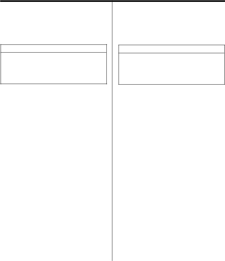
Figure 1. Diagram of the Vienna-I |
Figure 1. Schéma du modèle Vienna-I |
||
10 1/2 (267mm) |
|
|
7 (179mm) |
18 3/4 (478mm) |
15 1/4 (387mm) |
21 (533mm) |
Ø6 5/8 (168mm) |
|
|
27 1/8 |
26 1/8 |
(688mm) |
(664mm) |
|
6 7/8 |
|
(175mm) |
Getting Started (continued) |
Mise en marche (suite) |
|
|
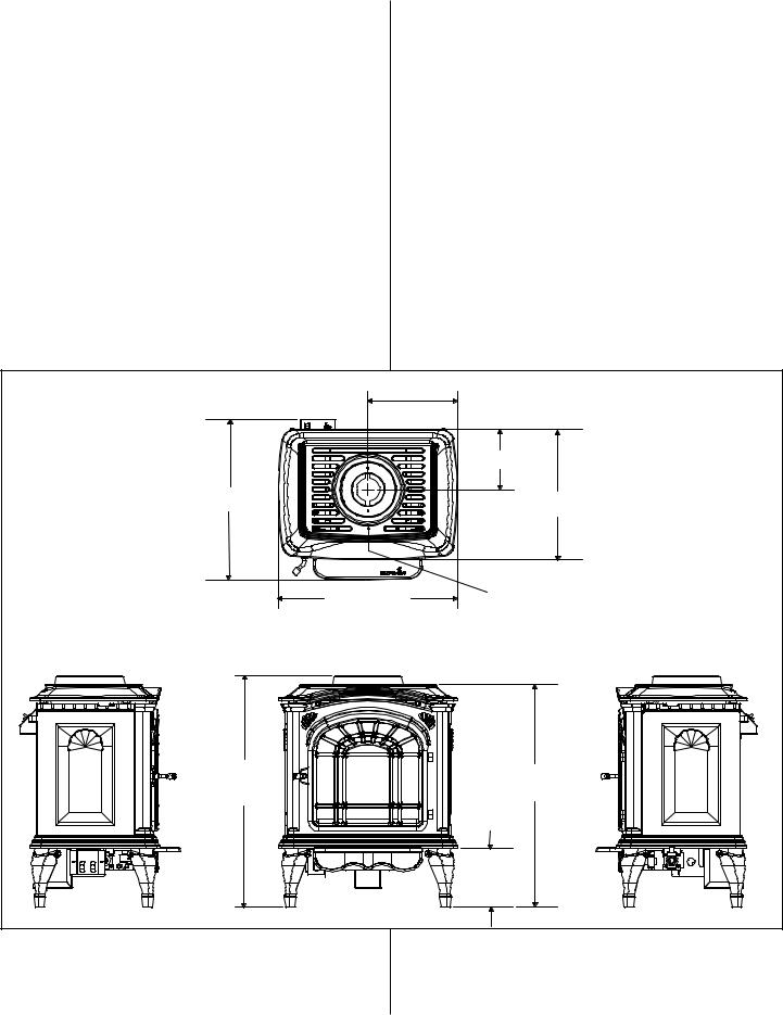
Figure 2. Diagram of the Vienna-II |
Figure 2. Schéma du modèle Vienna-II |
|
14 3/4 (375mm) |
|
|
Ø6 5/8 (168mm) |
|
|
7 (179mm) |
|
19 3/8 (491mm) |
|
15 1/4 (387mm) |
|
|
|
|
29 1/2 (749mm) |
|
30 1/8 |
|
29 1/4 |
(766mm) |
6 7/8 |
(742mm) |
|
(174mm) |
|
13
 Loading...