


Owner’s Manual
Installation and Operation
Models: 6000CLX-IPI-T 6000CLX-IPILP-T 6000CLX-IPI-S 6000CLX-IPILP-S 8000CLX-IPI-T 8000CLX-IPILP-T 8000CLX-IPI-S 8000CLX-IPILP-S
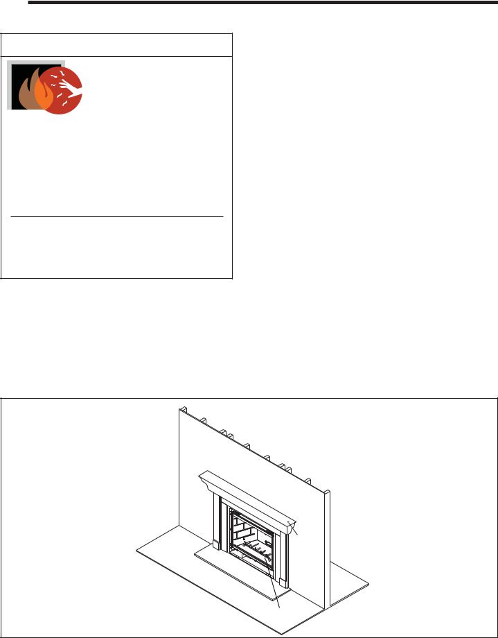
NOTICE
DO NOT DISCARD THIS MANUAL
• Important operating |
• Read, understand and follow |
• Leave this manual with |
and maintenance |
these instructions for safe |
party responsible for use |
instructions included. |
installation and operation. |
and operation. |
DO DISCARDNOT
 WARNING: If the information in these instructions is not followed exactly, a fire or explosion may result causing property damage, personal injury, or death.
•DO NOT store or use gasoline or other flammable vapors and liquids in the vicinity of this or any other appliance.
•What to do if you smell gas
-DO NOT try to light any appliance.
-DO NOT touch any electrical switch. DO NOT use any phone in your building.
-Immediately call your gas supplier from a neighbor’s phone. Follow the gas supplier’s instructions.
-If you cannot reach your gas supplier, call the fire department.
•Installation and service must be performed by a qualified installer, service agency, or the gas supplier.
This appliance may be installed as an OEM installation in manufactured home (USA only) or mobile home and must be installed in accordance with the manufacturer’s instructions and the manufactured home construction and safety standard,
Title 24 CFR, Part 3280 or Standard for Installation in Mobile Homes, CAN/CSA Z240MH, in Canada.
This appliance is only for use with the type(s) of gas indicated on the rating plate.
 WARNING
HOT SURFACES!
Glass and other surfaces are hot during operation AND cool down.
Hot glass will cause burns.
• DO NOT touch glass until it is cooled
•NEVER allow children to touch glass
•Keep children away
•CAREFULLY SUPERVISE children in same room as fireplace.
•Alert children and adults to hazards of high temperatures.
High temperatures may ignite clothing or other flammable materials.
•Keep clothing, furniture, draperies and other flammable materials away.
This appliance has been supplied with an integral barrier to prevent direct contact with the fixed glass panel. DO NOT operate the appliance with the barrier removed.
Contact your dealer or Hearth & Home Technologies if the barrier is not present or help is needed to properly install one.
In the Commonwealth of Massachusetts installation must be performed by a licensed plumber or gas fitter.
See Table of Contents for location of additional Commonwealth of Massachusetts requirements.
Installation and service of this appliance should be performed by qualified personnel. Hearth & Home Technologies suggests NFI certified or factory trained professionals, or technicians supervised by an NFI certified professional.
Heat & Glo • 6000CLX-IPI-S, 6000CLX-IPI-T, 8000CLX-S, 8000CLX-IPI-T • 2166-900 Rev. G • 12/09 |
1 |
Read this manual before installing or operating this appliance.
Please retain this owner’s manual for future reference.
A. Congratulations
Congratulations on selecting a Heat & Glo gas fireplace, an elegant and clean alternative to wood burning fireplaces. The Heat & Glo gas fireplace you have selected is designed to provide the utmost in safety, reliability, and efficiency.
As the owner of a new fireplace, you’ll want to read and carefully follow all of the instructions contained in this owner’s manual. Pay special attention to all cautions and warnings.
This owner’s manual should be retained for future reference. We suggest that you keep it with your other important documents and product manuals.
The information contained in this owner’s manual, unless noted otherwise, applies to all models and gas control systems.
Your new Heat & Glo gas fireplace will give you years of durable use and trouble-free enjoyment. Welcome to the Heat & Glo family of fireplace products!
Homeowner Reference Information
We recommend that you record the following pertinent information about your fireplace.
Model Name: ___________________________________________ Date purchased/installed:__________________
Serial Number:__________________________________________ Location on fireplace: _____________________
Dealership purchased from: _______________________________ Dealer Phone: __________________________
Notes: _______________________________________________________________________________________
_____________________________________________________________________________________________
Listing Label Information/Location The model information regarding your specific fireplace can be found on the rating plate usually located in the control area of the fireplace.
Type of Gas
Gas and Electric
Information
This product may be covered by one or more of the following patents: (Nos produits sont couverts par un ou plusieurs des brevets suivants): (United States) 4593510, 4686807, 4766876, 4793322, 4811534, 5000162, 5016609, 5076254, 5113843, 5191877, 5218953, 5263471, 5328356, 5341794, 5347983, 5429495, 5452708, 5542407, 5601073, 5613487, 5647340, 5688568, 5762062, 5775408, 5890485, 5931661, 5941237, 5947112, 5996575, 6006743, 6019099, 6048195, 6053165, 6145502, 6170481, 6237588, 6296474, 6374822, 6413079, 6439226, 6484712, 6543698, 6550687, 6601579, 6672860, 6688302B2, 6715724B2, 6729551, 6736133, 6748940, 6748942, D320652, D445174, D462436; (Canada)1297749, 2195264, 2225408; or other U.S. and foreign patents pending (ou autres brevets americains et etrangers en attente).
Heat & Glo, a brand of Hearth & Home Technologies, Inc. 7571 215th Street West, Lakeville, MN 55044
Not for use with solid fuel.
(Ne doit pas entre utilise avec un combustible solide).
Type of Gas (Sorte De Gaz): This appliance must be installed in accordance with local codes, if any; if not, follow ANSI Z223.1 in the USA or CAN/CGA B149 installation codes. (Installer l’appareil selon les codes ou reglements locaux ou, en l’absence de tels reglements, selon les codes d’installation CAN/CGA-B149.)
ANSI Z21XX-XXXX · CSA 2.XX-MXX · UL307B
Minimum Permissible Gas Supply for Purposes of Input Adjustment. |
|
|
|
||||||
Approved Minimum (De Gaz) Acceptable |
0.0 in w.c. |
(Po. Col. d’eau) |
|
|
|
||||
Maximum Pressure (Pression) |
|
0.0 in w.c. |
(Po. Col. d’eau) |
|
|
|
|||
Maximum Manifold Pressure (Pression) |
0.0 in w.c. |
(Po. Col. d’eau) |
|
|
|
||||
Minimum Manifold Pressure (Pression) |
0.0 in w.c. |
(Po. Col. d’eau) |
|
|
|
||||
Total Electrical Requirements: 000Vac, 00Hz., less than 00 Amperes |
MADE IN USA |
|
|
||||||
|
|
|
|
|
|
|
|
|
|
|
|
IN CANADA |
|
Model: |
XXXXXXXX |
|
|||
ALTITUDE: |
0-0000 FT. |
0000-0000FT. |
|
||||||
(Modele): |
|
||||||||
MAX. INPUT BTUH: |
00,000 |
00,000 |
|
|
|
|
|
|
|
MIN. INPUT BTUH: |
00,000 |
00,000 |
|
Serial |
XXXXXXXX |
|
|||
ORIFICE SIZE: |
#XXXXX |
#XXXXX |
|
|
|||||
|
(Serie): |
|
|||||||
Model Number
Serial Number
2 |
Heat & Glo • 6000CLX-IPI-S, 6000CLX-IPI-T, 8000CLX-S, 8000CLX-IPI-T • 2166-900 Rev. G • 12/09 |
 Safety Alert Key:
•DANGER! Indicates a hazardous situation which, if not avoided will result in death or serious injury.
•WARNING! Indicates a hazardous situation which, if not avoided could result in death or serious injury.
•CAUTION! Indicates a hazardous situation which, if not avoided, could result in minor or moderate injury.
•NOTICE: Used to address practices not related to personal injury.
Table of Contents
A. Congratulations . . . . . . . . . . . . . . . . . . . . . . . . . . . . . . . . . 2
B. Limited Lifetime Warranty. . . . . . . . . . . . . . . . . . . . . . . . . . 5
1 Listing and Code Approvals
A. Appliance Certification . . . . . . . . . . . . . . . . . . . . . . . . . . . . 7 B. Glass Specifications. . . . . . . . . . . . . . . . . . . . . . . . . . . . . . 7 C. BTU Specifications. . . . . . . . . . . . . . . . . . . . . . . . . . . . . . . 7 D. High Altitude Installations . . . . . . . . . . . . . . . . . . . . . . . . . . 7 E. Non-Combustible Materials Specification. . . . . . . . . . . . . . 7 F. Combustible Materials Specification . . . . . . . . . . . . . . . . . 7 G. Electrical Codes . . . . . . . . . . . . . . . . . . . . . . . . . . . . . . . . . 7 H. Requirements for the Commonwealth of Massachusetts. . 8
User Guide
2 Operating Instructions
A. Gas Fireplace Safety . . . . . . . . . . . . . . . . . . . . . . . . . . . . . 9 B. Your Fireplace . . . . . . . . . . . . . . . . . . . . . . . . . . . . . . . . . . 9 C. Fan Kit . . . . . . . . . . . . . . . . . . . . . . . . . . . . . . . . . . . . . . . 10 D. Clear Space . . . . . . . . . . . . . . . . . . . . . . . . . . . . . . . . . . . 10 E. Decorative Doors and Fronts . . . . . . . . . . . . . . . . . . . . . . 10 F. Fixed Glass Assembly . . . . . . . . . . . . . . . . . . . . . . . . . . . 10 G. Remote Controls, Wall Controls and Wall Switches. . . . . 10 H. Before Lighting Fireplace . . . . . . . . . . . . . . . . . . . . . . . . . 10 I. Lighting Instructions (IPI) . . . . . . . . . . . . . . . . . . . . . . . . . 11 J. After Fireplace is Lit . . . . . . . . . . . . . . . . . . . . . . . . . . . . . 12 K. Frequently Asked Questions . . . . . . . . . . . . . . . . . . . . . . 12
3 Maintenance and Service
A. Maintenance Tasks-Homeowner . . . . . . . . . . . . . . . . . . . 13
B. Maintenance Tasks-Qualified Service Technician . . . . . . 14
C. Refractory, Grate and Valve Assembly Removal . . . . . . . 15
D. Burner Identification/Verification. . . . . . . . . . . . . . . . . . . . 16
Installer Guide
4 Getting Started
A. Typical Appliance System. . . . . . . . . . . . . . . . . . . . . . . . . 17
B. Design and Installation Considerations . . . . . . . . . . . . . . 18
C. Tools and Supplies Needed . . . . . . . . . . . . . . . . . . . . . . . 18
D. Inspect Appliance and Components. . . . . . . . . . . . . . . . . 18
5 Framing and Clearances
A. Selecting Appliance Location . . . . . . . . . . . . . . . . . . . . . . 19
B. Constructing the Appliance Chase . . . . . . . . . . . . . . . . . . 20
C. Clearances . . . . . . . . . . . . . . . . . . . . . . . . . . . . . . . . . . . . 20
D. Mantel and Wall Projections. . . . . . . . . . . . . . . . . . . . . . . 21
6 Termination Locations
A. Vent Termination Minimum Clearances . . . . . . . . . . . . . . 22
7 Vent Information and Diagrams
A. Approved Pipe . . . . . . . . . . . . . . . . . . . . . . . . . . . . . . . . . 24
B. Vent Table Key . . . . . . . . . . . . . . . . . . . . . . . . . . . . . . . . . 24
C. Use of Elbows . . . . . . . . . . . . . . . . . . . . . . . . . . . . . . . . . 24
D. Measuring Standards . . . . . . . . . . . . . . . . . . . . . . . . . . . . 24
E. Vent Diagrams . . . . . . . . . . . . . . . . . . . . . . . . . . . . . . . . . 25
8 Vent Clearances and Framing
A. Pipe Clearances to Combustibles . . . . . . . . . . . . . . . . . . 35 B. Wall Penetration Framing. . . . . . . . . . . . . . . . . . . . . . . . . 35 C. Install the Ceiling Firestop . . . . . . . . . . . . . . . . . . . . . . . . 36 D. Install Attic Insulation Shield. . . . . . . . . . . . . . . . . . . . . . . 37 E. Installing the Optional Heat-Zone-Gas Kit . . . . . . . . . . . . 37
9 Appliance Preparation
A. Top Vent . . . . . . . . . . . . . . . . . . . . . . . . . . . . . . . . . . . . . . 38
B. Rear Vent . . . . . . . . . . . . . . . . . . . . . . . . . . . . . . . . . . . . . 39
C. Installing the Non-combustible Board. . . . . . . . . . . . . . . . 40
D. Securing and Leveling the Appliance . . . . . . . . . . . . . . . . 40
10 Installing Vent Pipe (DVP and SLP Pipe)
A. Assemble Vent Sections (DVP Pipe Only) . . . . . . . . . . . . 41 B. Assemble Vent Sections (SLP Pipe Only) . . . . . . . . . . . . 42 C. Assemble Slip Sections . . . . . . . . . . . . . . . . . . . . . . . . . . 42 D. Secure the Vent Sections. . . . . . . . . . . . . . . . . . . . . . . . . 43 E. Disassemble Vent Sections . . . . . . . . . . . . . . . . . . . . . . . 43 F. Install Decorative Ceiling Components (SLP only). . . . . . 44 G. Install Metal Roof Flashing. . . . . . . . . . . . . . . . . . . . . . . . 45 H. Assemble and Install Storm Collar . . . . . . . . . . . . . . . . . . 45 I. Install Vertical Termination Cap . . . . . . . . . . . . . . . . . . . . 46 J. Install Decorative Wall Components (SLP only). . . . . . . . 46 K. Heat Shield Requirements for Horizontal Termination . . . 46 L. Install Horizontal Termination Cap (DVP and SLP Pipe) . 47
11 Gas Information
A. Fuel Conversion . . . . . . . . . . . . . . . . . . . . . . . . . . . . . . . . 48
B. Gas Pressure . . . . . . . . . . . . . . . . . . . . . . . . . . . . . . . . . . 48
C. Gas Connection . . . . . . . . . . . . . . . . . . . . . . . . . . . . . . . . 48
D. High Altitude Installations . . . . . . . . . . . . . . . . . . . . . . . . . 48
12 Electrical Information
A. Wiring Requirements . . . . . . . . . . . . . . . . . . . . . . . . . . . . 49 B. IntelliFire PlusTM Ignition System Wiring. . . . . . . . . . . . . . 49 C. Optional Accessories Requirements . . . . . . . . . . . . . . . . 49 D. Electrical Service and Repair . . . . . . . . . . . . . . . . . . . . . . 50 E. Junction Box Installation. . . . . . . . . . . . . . . . . . . . . . . . . . 50 F. Wall Switch Installation for Fan . . . . . . . . . . . . . . . . . . . . 50 G. Control Module Operation . . . . . . . . . . . . . . . . . . . . . . . . 51
Heat & Glo • 6000CLX-IPI-S, 6000CLX-IPI-T, 8000CLX-S, 8000CLX-IPI-T • 2166-900 Rev. G • 12/09 |
3 |
13 Finishing
A. Mantel and Wall Projections. . . . . . . . . . . . . . . . . . . . . . . 52
B. Facing Material. . . . . . . . . . . . . . . . . . . . . . . . . . . . . . . . . 52
C. Doors . . . . . . . . . . . . . . . . . . . . . . . . . . . . . . . . . . . . . . . . 53
D. Elevated Hearth Systems. . . . . . . . . . . . . . . . . . . . . . . . . 56
14 Appliance Setup
A. Remove Fixed Glass Assembly . . . . . . . . . . . . . . . . . . . . 57 B. Remove the Shipping Materials . . . . . . . . . . . . . . . . . . . . 57 C. Clean the Appliance . . . . . . . . . . . . . . . . . . . . . . . . . . . . . 57 D. Accessories . . . . . . . . . . . . . . . . . . . . . . . . . . . . . . . . . . . 57 E. Burner Top Installation . . . . . . . . . . . . . . . . . . . . . . . . . . . 57 F. Refractory Installation. . . . . . . . . . . . . . . . . . . . . . . . . . . . 58 G. Ember Placement. . . . . . . . . . . . . . . . . . . . . . . . . . . . . . . 59 H. Teco-Sil Placement. . . . . . . . . . . . . . . . . . . . . . . . . . . . . . 60 I. Install the Log Assembly. . . . . . . . . . . . . . . . . . . . . . . . . . 61 J. Fixed Glass Assembly . . . . . . . . . . . . . . . . . . . . . . . . . . . 65 K. Install Trim and/or Surround. . . . . . . . . . . . . . . . . . . . . . . 65 L. Air Shutter Setting . . . . . . . . . . . . . . . . . . . . . . . . . . . . . . 65
15 Troubleshooting
A. IntelliFire Plus™ Ignition System . . . . . . . . . . . . . . . . . . . 66
16 Reference Materials
A. Appliance Dimension Diagram. . . . . . . . . . . . . . . . . . . . . 68
B. Vent Components Diagrams . . . . . . . . . . . . . . . . . . . . . . 70
C. Service Parts . . . . . . . . . . . . . . . . . . . . . . . . . . . . . . . . . . 77
D. Contact Information . . . . . . . . . . . . . . . . . . . . . . . . . . . . . 82
Î = Contains updated information.
4 |
Heat & Glo • 6000CLX-IPI-S, 6000CLX-IPI-T, 8000CLX-S, 8000CLX-IPI-T • 2166-900 Rev. G • 12/09 |
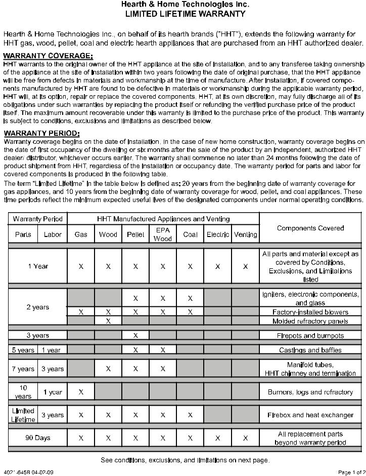
B. Limited Lifetime Warranty
Heat & Glo • 6000CLX-IPI-S, 6000CLX-IPI-T, 8000CLX-S, 8000CLX-IPI-T • 2166-900 Rev. G • 12/09 |
5 |

6 |
Heat & Glo • 6000CLX-IPI-S, 6000CLX-IPI-T, 8000CLX-S, 8000CLX-IPI-T • 2166-900 Rev. G • 12/09 |
1 Listing and Code Approvals
A. Appliance Certification
MODELS: 6000CLX-IPI, 6000CLX-IPILP, 8000CLX-IPI,
8000CLX-IPILP
LABORATORY: Underwriters Laboratories, Inc. (UL)
TYPE: Direct Vent Gas Appliance Heater
STANDARD: ANSI Z21.88b-2008 • CSA 2.33a-2008
This product is listed to ANSI standards for “Vented Gas Appliance Heaters” and applicable sections of “Gas Burning Heating Appliances for Manufactured Homes and Recreational Vehicles”, and “Gas Fired Appliances for Use at High Altitudes”.
NOTICE: This installation must conform with local codes. In the absence of local codes you must comply with the National Fuel Gas Code, ANSI Z223.1-latest edition in the U.S.A. and the CAN/CGA B149 Installation Codes in Canada.
NOT INTENDED FOR USE AS A PRIMARY HEAT SOURCE.
This appliance is tested and approved as either supplemental room heat or as a decorative appliance. It should not be factored as primary heat in residential heating calculations.
D. High Altitude Installations
NOTICE: If the heating value of the gas has been reduced, these rules do not apply. Check with your local gas utility or authorities having jurisdiction.
When installing above 2000 feet elevation:
•In the USA: Reduce input rate 4% for each 1000 feet above 2000 feet.
•In CANADA: Reduce input rate 10% for elevations between 2000 feet and 4500 feet. Above 4500 feet, consult local gas utility.
Check with your local gas utility to determine proper orifice size.
E. Non-Combustible Materials Specification
Material which will not ignite and burn. Such materials are those consisting entirely of steel, iron, brick, tile, concrete, slate, glass or plasters, or any combination thereof.
Materials that are reported as passing ASTM E 136,
Standard Test Method for Behavior of Materials in a Vertical Tube Furnace at 750 ºC and UL763 shall be considered non-combustible materials.
B. Glass Specifications
This appliance is equipped with 5 mm ceramic glass. Replace glass only with 5 mm ceramic glass. Please contact your dealer for replacement glass.
F. Combustible Materials Specification
Materials made of or surfaced with wood, compressed paper, plant fibers, plastics, or other material that can ignite and burn, whether flame proofed or not, or plastered or unplastered shall be considered combustible materials.
C. BTU Specifications
Models |
Maxi- |
Mini- |
Orifice |
||
mum |
mum |
||||
Size |
|||||
(U.S. or Canada) |
Input |
Input |
|||
(DMS) |
|||||
|
|
BTU/h |
BTU/h |
||
|
|
|
|||
|
US |
40,000 |
22,000 |
0.124 |
|
|
(0-2000 FT) |
in. |
|||
6000CLX-IPI (NG) |
|
|
|||
CANADA |
36,000 |
19,800 |
32 |
||
|
|||||
|
(2000-4500 FT) |
||||
|
|
|
|
||
|
|
|
|
|
|
|
US |
40,000 |
21,000 |
49 |
|
|
(0-2000 FT) |
||||
6000CLX-IPILP |
|
|
|
||
CANADA |
36,000 |
18,900 |
50 |
||
|
|||||
|
(2000-4500 FT) |
||||
|
|
|
|
||
|
|
|
|
|
|
|
US |
45,000 |
22,000 |
30 |
|
|
(0-2000 FT) |
||||
8000CLX-IPI (NG) |
|
|
|
||
CANADA |
40,500 |
19,800 |
31 |
||
|
|||||
|
(2000-4500 FT) |
||||
|
|
|
|
||
|
US |
45,000 |
23,000 |
47 |
|
|
(0-2000 FT) |
||||
|
|
|
|
||
8000CLX-IPILP |
CANADA |
40,500 |
20,700 |
48 |
|
|
(2000-4500 FT) |
||||
|
|
|
|
||
|
|
|
|
|
|
G. Electrical Codes
NOTICE: This appliance must be electrically wired and grounded in accordance with local codes or, in the absence of local codes, with National Electric Code ANSI/NFPA 70-latest edition or the Canadian Electric Code CSA
C22.1.
•A 110-120 VAC circuit for this product must be protected with ground-fault circuit-interrupter protection, in compliance with the applicable electrical codes, when it is installed in locations such as in bathrooms or near sinks.
Heat & Glo • 6000CLX-IPI-S, 6000CLX-IPI-T, 8000CLX-S, 8000CLX-IPI-T • 2166-900 Rev. G • 12/09 |
7 |
Note: The following requirements reference various Massachusetts and national codes not contained in this document.
H.Requirements for the Commonwealth of Massachusetts
For all side wall horizontally vented gas fueled equipment installed in every dwelling, building or structure used in whole or in part for residential purposes, including those owned or operated by the Commonwealth and where the side wall exhaust vent termination is less than seven (7) feet above finished grade in the area of the venting, including but not limited to decks and porches, the following requirements shall be satisfied:
Installation of Carbon Monoxide Detectors
At the time of installation of the side wall horizontal vented gas fueled equipment, the installing plumber or gas fitter shall observe that a hard wired carbon monoxide detector with an alarm and battery back-up is installed on the floor level where the gas equipment is to be installed. In addition, the installing plumber or gas fitter shall observe that a battery operated or hard wired carbon monoxide detector with an alarm is installed on each additional level of the dwelling, building or structure served by the side wall horizontal vented gas fueled equipment. It shall be the responsibility of the property owner to secure the services of qualified licensed professionals for the installation of hard wired carbon monoxide detectors.
In the event that the side wall horizontally vented gas fueled equipment is installed in a crawl space or an attic, the hard wired carbon monoxide detector with alarm and battery back-up may be installed on the next adjacent floor level.
In the event that the requirements of this subdivision can not be met at the time of completion of installation, the owner shall have a period of thirty (30) days to comply with the above requirements; provided, however, that during said thirty (30) day period, a battery operated carbon monoxide detector with an alarm shall be installed.
Approved Carbon Monoxide Detectors
Each carbon monoxide detector as required in accordance with the above provisions shall comply with NFPA 720 and be ANSI/UL 2034 listed and IAS certified.
Signage
A metal or plastic identification plate shall be permanently mounted to the exterior of the building at a minimum height of eight (8) feet above grade directly in line with the exhaust vent terminal for the horizontally vented gas fueled heating appliance or equipment. The sign shall read, in print size no less than one-half (1/2) in. in size, “GAS
VENT DIRECTLY BELOW. KEEP CLEAR OF ALL OBSTRUCTIONS”.
Inspection
The state or local gas inspector of the side wall horizontally vented gas fueled equipment shall not approve the installation unless, upon inspection, the inspector observes carbon monoxide detectors and signage installed in accordance with the provisions of 248 CMR 5.08(2)(a)1 through 4.
Exemptions
The following equipment is exempt from 248 CMR 5.08(2)(a)1 through 4:
•The equipment listed in Chapter 10 entitled “Equipment Not Required To Be Vented” in the most current edition of NFPA 54 as adopted by the Board; and
•Product Approved side wall horizontally vented gas fueled equipment installed in a room or structure separate from the dwelling, building or structure used in whole or in part for residential purposes.
MANUFACTURER REQUIREMENTS
Gas Equipment Venting System Provided
When the manufacturer of Product Approved side wall horizontally vented gas equipment provides a venting system design or venting system components with the equipment, the instructions provided by the manufacturer for installation of the equipment and the venting system shall include:
•Detailed instructions for the installation of the venting system design or the venting system components; and
•A complete parts list for the venting system design or venting system.
Gas Equipment Venting System NOT Provided
When the manufacturer of a Product Approved side wall horizontally vented gas fueled equipment does not provide the parts for venting the flue gases, but identifies “special venting systems”, the following requirements shall be satisfied by the manufacturer:
•The referenced “special venting system” instructions shall be included with the appliance or equipment installation instructions; and
•The “special venting systems” shall be Product Approved by the Board, and the instructions for that system shall include a parts list and detailed installation instructions.
A copy of all installation instructions for all Product Approved side wall horizontally vented gas fueled equipment, all venting instructions, all parts lists for venting instructions, and/or all venting design instructions shall remain with the appliance or equipment at the completion of the installation.
See Gas Connection section for additional Commonwealth of Massachusetts requirements.
8 |
Heat & Glo • 6000CLX-IPI-S, 6000CLX-IPI-T, 8000CLX-S, 8000CLX-IPI-T • 2166-900 Rev. G • 12/09 |
2 Operating Instructions User Guide
A. Gas Fireplace Safety
 WARNING
HOT SURFACES!
Glass and other surfaces are hot during operation AND cool down.
Hot glass will cause burns.
• DO NOT touch glass until it is cooled
•NEVER allow children to touch glass
•Keep children away
•CAREFULLY SUPERVISE children in same room as fireplace.
•Alert children and adults to hazards of high temperatures.
High temperatures may ignite clothing or other flammable materials.
•Keep clothing, furniture, draperies and other flammable materials away.
This appliance has been supplied with an integral barrier to prevent direct contact with the fixed glass panel. DO NOT operate the appliance with the barrier removed.
Contact your dealer or Hearth & Home Technologies if the barrier is not present or help is needed to properly install one.
If you expect that small children or vulnerable adults may come into contact with this fireplace, the following precautions are recommended:
•Install a physical barrier such as:
-A decorative firescreen.
-Adjustable safety gate.
•Install a switch lock or a wall/remote control with child protection lockout feature.
•Keep remote controls out of reach of children.
•Never leave children alone near a hot fireplace, whether operating or cooling down.
•Teach children to NEVER touch the fireplace.
•Consider not using the fireplace when children will be present.
Contact your dealer for more information, or visit: www. hpba.org/staysafe.
To prevent unintended operation when not using your fireplace for an extended period of time (summer months, vacations, trips, etc):
•Remove batteries from remote controls.
•Turn off wall controls.
•Unplug 6 volt transformer plug and remove batteries on IPI models.
•Turn off gas controls valve on standing pilot models.
When lighting the pilot light on fireplaces with a standing pilot, remove the fixed glass assembly so you can detect presence of residual gas build-up. See Standing Pilot Lighting instructions and Maintenance Tasks.
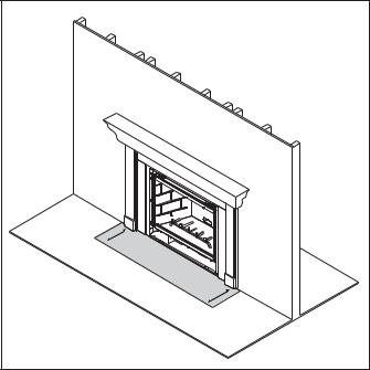
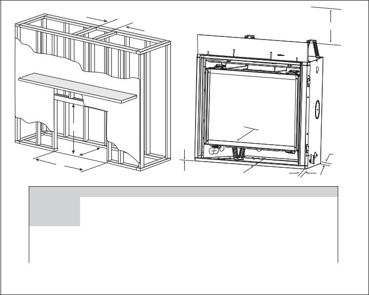
B. Your Fireplace
WARNING! DO NOT operate fireplace before reading and understanding operating instructions. Failure to operate fireplace according to operating instructions could cause fire or injury.
DECORATIVE DOORS
(NOT SHOWN)
SECTION 2.E.
FIXED GLASS ASSEMBLY
(NOT SHOWN)
SECTION 14.J.
MANTEL
SECTION 5.D
FAN KIT
SECTION 2.C.
HEARTH
CLEAR SPACE
SECTION 2.D.
GRATE
SECTION 3.C.
Figure 2.1 General Operating Parts
Heat & Glo • 6000CLX-IPI-S, 6000CLX-IPI-T, 8000CLX-S, 8000CLX-IPI-T • 2166-900 Rev. G • 12/09 |
9 |
C. Fan Kit
A fan is shipped with this appliance.
D. Clear Space
WARNING! DO NOT place combustible objects in front of the fireplace or block louvers. High temperatures may start a fire. See Figure 2.2.
Avoid placing candles and other heat-sensitive objects on mantel or hearth. Heat may damage these objects.
|
3 |
FT. |
CLEAR |
|
|
||
|
|
IN |
|
|
|
|
FRONT OFSPACE |
|
|
|
FIREPLACE |
Figure 2.2 |
Clear Space |
|
|
E. Decorative Doors and Fronts
WARNING! Risk of Fire! Install ONLY doors or fronts approved by Hearth & Home Technologies. Unapproved doors or fronts may cause fireplace to overheat.
This fireplace has been supplied with an integral barrier to prevent direct contact with the fixed glass panel. DO NOT operate the fireplace with the barrier removed.
Contact your dealer or Hearth & Home Technologies if the barrier is not present or help is needed to properly install one.
For more information refer to the instructions supplied with your decorative door or front.
F. Fixed Glass Assembly
See Section 14.J.
G.Remote Controls, Wall Controls and Wall Switches
Follow the instructions supplied with the control installed to operate your fireplace:
For safety:
•Install a switch lock or a wall/remote control with child protection lockout feature.
•Keep remote controls out of reach of children.
See your dealer if you have questions.
H. Before Lighting Fireplace
Before operating this fireplace for the first time, have a qualified service technician:
•Verify all shipping materials have been removed from inside and/or underneath the firebox.
•Review proper placement of logs, ember material and/or other decorative materials.
•Ensure plastic finishing strips have been removed after use for incorporating finishing materials.
•Check the wiring.
•Check the air shutter adjustment.
•Ensure that there are no gas leaks.
•Ensure that the glass is sealed and in the proper position and that the integral barrier is in place.
WARNING! Risk of Fire or Asphyxiation! DO NOT operate fireplace with fixed glass assembly removed.
10 |
Heat & Glo • 6000CLX-IPI-S, 6000CLX-IPI-T, 8000CLX-S, 8000CLX-IPI-T • 2166-900 Rev. G • 12/09 |
I. Lighting Instructions (IPI)
FOR YOUR SAFETY
READ BEFORE LIGHTING
WARNING: If you do not follow these instructions exactly, a fire or explosion may result causing property damage, personal injury or loss of life.
A.This appliance is equipped with an intermittent pilot ignition (IPI) device which automatically lights the burner. DO NOT try to light the burner by hand.
B.BEFORE LIGHTING, smell all around the appliance area for gas. Be sure to smell next to the floor because some gas is heavier than air and will settle on the floor.
WHAT TO DO IF YOU SMELL GAS
•DO NOT try to light any appliance.
•DO NOT touch any electric switch; do not use any phone in your building.
•Immediately call your gas supplier from a neighbor’s phone. Follow the gas supplier’s instructions.
•If you cannot reach your gas supplier, call the fire department.
C.DO NOT use this appliance if any part has been under water. Immediately call a qualified service technician to inspect the appliance and to replace any part of the control system and any gas control which has been under water.
WARNING: 
 CAUTION:
DO NOT CONNECT LINE VOLTAGE (110/120 VAC OR 220/240 VAC) TO THE CONTROL VALVE.
Improper installation, adjustment, alteration, service or maintenance can cause injury or property damage. Refer to the owner’s information manual provided with this appliance.
This appliance needs fresh air for safe operation and must be installed so there are provisions for adequate combustion and ventilation air.
If not installed, operated, and maintained in accordance with the manufacturer’s instructions, this product could expose you to substances in fuel or fuel combustion which are known to the State of California to cause cancer, birth defects, or other reproductive harm.
Keep burner and control compartment clean. See installation and operating instructions accompanying appliance.
Hot while in operation. DO NOT touch. Keep children, clothing, furniture, gasoline and other liquids having flammable vapors away.
DO NOT operate the appliance with fixed glass assembly removed, cracked or broken. Replacement of the fixed glass assembly should be done by a licensed or qualified service person.
NOT FOR USE
WITH SOLID FUEL
For use with natural gas and propane. A conversion kit, as supplied by the manufacturer, shall be used to convert this appliance to the alternate fuel.
Also Certified for Installation in a Bedroom or a Bedsitting Room.
For assistance or additional information, consult a qualified installer, service agency or the gas supplier.
For additional information on operating your
Hearth & Home Technologies fireplace, please refer to www.fireplaces.com.
Final inspection by

 LIGHTING
INSTRUCTIONS (IPI)
1.This appliance is equipped with an ignition device which automatically lights the burner. DO NOT try to light the burner by hand.
GAS
VALVE
2.Wait five (5) minutes to clear out any gas. Then smell for gas, including near the floor. If you smell gas, STOP! Follow “B” in the Safety Information located on the left side of this label. If you do not smell gas, go to next step.
3.To light the burner:
Equipped with wall switch: Turn ON/OFF switch to ON.
Equipped with remote or wall control: Press ON or FLAME button.
Equipped with thermostat: Set temperature to desired setting.
4.If the appliance does not light after three tries, call your service technician or gas supplier.

 TO TURN OFF
 GAS TO APPLIANCE
1.Equipped with wall switch: Turn ON/OFF switch to OFF.
Equipped with remote or wall control: Press OFF button.
Equipped with thermostat: Set temperature to lowest setting.
2.Service technician should turn off electric power to the control when performing service.
593-913G
Heat & Glo • 6000CLX-IPI-S, 6000CLX-IPI-T, 8000CLX-S, 8000CLX-IPI-T • 2166-900 Rev. G • 12/09 |
11 |

J. After Fireplace is Lit
Initial Break-in Procedure
•The fireplace should be run three to four hours continuously on high.
•Turn the fireplace off and allow it to completely cool.
•Remove fixed glass assembly. See Section 14.J.
•Clean fixed glass assembly. See Section 3.
•Replace the fixed glass assembly and run continuously on high an additional 12 hours.
This cures the materials used to manufacture the fireplace.
NOTICE! Open windows for air circulation during fireplace break-in.
•Some people may be sensitive to smoke and odors.
•Smoke detectors may activate.
K.Frequently Asked Questions
ISSUE |
SOLUTIONS |
|
|
|
|
Condensation on the glass |
This is a result of gas combustion and temperature variations. As the appliance warms, this |
|
condensation will disappear. |
||
|
||
Blue flames |
This is a result of normal operation and the flames will begin to yellow as the appliance is al- |
|
lowed to burn for 20 to 40 minutes. |
||
|
||
|
When first operated, this appliance may release an odor for the first several hours. This is caused |
|
Odor from appliance |
by the curing of the paint and the burning off of any oils remaining from manufacturing. Odor may |
|
|
also be released from finishing materials and adhesives used around the appliance. |
|
|
This is a normal result of the curing process of the paint and logs. Glass should be cleaned |
|
Film on the glass |
within 3 to 4 hours of initial burning to remove deposits left by oils from the manufacturing |
|
|
process. A non-abrasive cleaner such as gas fireplace glass cleaner may be necessary. See |
|
|
your dealer. |
|
|
Noise is caused by metal expanding and contracting as it heats up and cools down, similar to |
|
Metallic noise |
the sound produced by a furnace or heating duct. This noise does not affect the operation or |
|
|
longevity of the appliance. |
|
Is it normal to see the pilot flame burn |
In an intermittent pilot ignition system (IPI), the pilot flame should turn off when appliance is |
|
turned off. Some optional control systems available with IPI models may allow pilot flame to |
||
continually? |
remain lit. |
|
|
||
|
|
12 |
Heat & Glo • 6000CLX-IPI-S, 6000CLX-IPI-T, 8000CLX-S, 8000CLX-IPI-T • 2166-900 Rev. G • 12/09 |

3 Maintenance and Service
Any safety screen or guard removed for servicing must be replaced prior to operating the fireplace.
When properly maintained, your fireplace will give you many years of trouble-free service. We recommend annual service by a qualified service technician.
Doors, Surrounds, Fronts
Frequency: Annually
By: Homeowner
Tools needed: Protective gloves, stable work surface
• Assess condition of screen and replace as necessary.
A. Maintenance Tasks-Homeowner
Installation and repair should be done by a qualified service technician only. The fireplace should be inspected before use and at least annually by a professional service person.
The following tasks may be performed annually by the homeowner. If you are uncomfortable performing any of the listed tasks, please call your dealer for a service appointment.
More frequent cleaning may be required due to lint from carpeting or other factors. Control compartment, burner and circulating air passageway of the fireplace must be kept clean.
CAUTION! Risk of Burns! The fireplace should be turned off and cooled before servicing.
Glass Cleaning
Frequency: Seasonally
By: Homeowner
Tools Needed: Protective gloves, glass cleaner, drop cloth and a stable work surface.
CAUTION! Handle fixed glass assembly with care.
Glass is breakable.
•Avoid striking, scratching or slamming glass
•Avoid abrasive cleaners
•DO NOT clean glass while it is hot
•Prepare a work area large enough to accommodate fixed glass assembly and door frame by placing a drop cloth on a flat, stable surface.
Note: Fixed glass assembly and gasketing may have residue that can stain carpeting or floor surfaces.
•Remove door or decorative front from fireplace and set aside on work surface.
•See Section 14.J for instructions to remove fixed glass assembly.
•Clean glass with a non-abrasive commercially available cleaner.
-Light deposits: Use a soft cloth with soap and water
-Heavy deposits: Use commercial fireplace glass cleaner (consult with your dealer)
•Carefully set fixed glass assembly in place on fireplace. Hold glass in place with one hand and secure glass latches with the other hand.
•Reinstall door or decorative front.
•Inspect for scratches, dents or other damage and repair as necessary.
•Check that louvers are not blocked.
•Vacuum and dust surfaces.
Remote Control
Frequency: Seasonally
By: Homeowner
Tools needed: Replacement batteries and remote control instructions.
•Locate remote control transmitter and receiver.
•Verify operation of remote. Refer to remote control operation instructions for proper calibration and setup procedure.
•Place batteries as needed in remote transmitters and battery-powered receivers.
•Place remote control out of reach of children.
If not using your fireplace for an extended period of time (summer months, vacations/trips, etc), to prevent unintended operation:
•Remove batteries from remote controls.
•Unplug 6 volt transformer plug on IPI models.
•Remove battery backup from control module.
Venting
Frequency: Seasonally
By: Homeowner
Tools needed: Protective gloves and safety glasses.
•Inspect venting and termination cap for blockage or obstruction such plants, bird nests, leaves, snow, debris, etc.
•Verify termination cap clearance to subsequent construction (building additions, decks, fences, or sheds). See Section 6.
•Inspect for corrosion or separation.
•Verify weather stripping, sealing and flashing remains intact.
•Inspect draft shield to verify it is not damaged or missing.
Heat & Glo • 6000CLX-IPI-S, 6000CLX-IPI-T, 8000CLX-S, 8000CLX-IPI-T • 2166-900 Rev. G • 12/09 |
13 |
B.Maintenance Tasks-Qualified Service Technician
The following tasks must be performed by a qualified service technician.
Gasket Seal and Glass Assembly Inspection
Frequency: Annually
By: Qualified Service Technician
Tools needed: Protective gloves, drop cloth and a stable work surface.
•Inspect gasket seal and its condition.
•Inspect fixed glass assembly for scratches and nicks that can lead to breakage when exposed to heat.
•Confirm there is no damage to glass or glass frame. Replace as necessary.
•Verify that fixed glass assembly is properly retained and attachment components are intact and not damaged. Replace as necessary.
Logs
Frequency: Annually
By: Qualified Service Technician
Tools needed: Protective gloves.
•Inspect for damaged or missing logs. Replace as necessary. Refer to Section 14 for log placement instructions.
•Verify correct log placement and no flame impingement causing sooting. Correct as necessary.
Firebox
Frequency: Annually
By: Qualified Service Technician
Tools needed: Protective gloves, sandpaper, steel wool, cloths, mineral spirits, primer and touch-up paint.
•Inspect for paint condition, warped surfaces, corrosion or perforation. Sand and repaint as necessary.
•Replace fireplace if firebox has been perforated.
Burner Ignition and Operation
Frequency: Annually
By: Qualified Service Technician
Tools needed: Protective gloves, vacuum cleaner, whisk broom, flashlight, voltmeter, indexed drill bit set, and a manometer.
•Verify burner is properly secured and aligned with pilot or igniter.
•Clean off burner top, inspect for plugged ports, corrosion or deterioration. Replace burner if necessary.
•Replace Glowing embers with new dime-size pieces. DO NOT block ports or obstruct lighting paths. Refer to Section 14 for proper ember placement.
•Verify batteries have been removed from battery backup IPI systems to prevent premature battery failure or leaking.
•Check for smooth lighting and ignition carryover to all ports. Verify that there is no ignition delay.
•Inspect for lifting or other flame problems.
•Verify air shutter setting is correct. See Section 14 for required air shutter setting. Verify air shutter is clear of dust and debris.
•Inspect orifice for soot, dirt and corrosion. Verify orifice size is correct. See Service Parts List for proper orifice sizing.
•Verify manifold and inlet pressures. Adjust regulator as required.
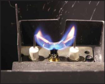
•Inspect pilot flame pattern and strength. See Figures 3.1 for proper pilot flame pattern. Clean or replace orifice spud as necessary.
•Inspect IPI flame sensing rod for soot, corrosion and deterioration. Clean with emery cloth or replace as required.
•Verify that there is not a short in flame sense circuit by checking continuity between pilot hood and flame sensing rod. Replace pilot as necessary.
Control Compartment and Firebox Top
Frequency: Annually
By: Qualified Service Technician
Tools needed: Protective gloves, vacuum cleaner, dust cloths
•Vacuum and wipe out dust, cobwebs, debris or pet hair. Use caution when cleaning these areas. Screw tips that have penetrated the sheet metal are sharp and should be avoided.
•Remove all foreign objects.
•Verify unobstructed air circulation.
Figure 3.1 IPI Pilot Flame Patterns
14 |
Heat & Glo • 6000CLX-IPI-S, 6000CLX-IPI-T, 8000CLX-S, 8000CLX-IPI-T • 2166-900 Rev. G • 12/09 |
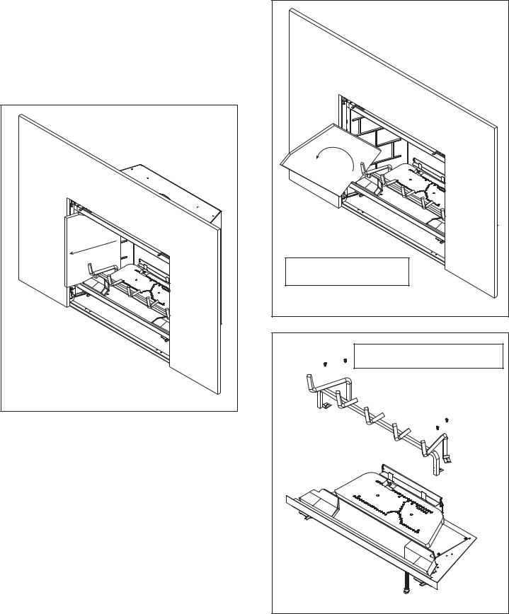
C.Refractory, Grate and Valve Assembly Removal
It may become necessary to remove the refractory, grate and valve assemblies. This task should be performed by a qualified service technician. the refractory, grate and base refractory do not need to be removed to service the burner assembly.
Figure 3.2 Side Refractory Removal |
To remove the top refractory panel, lift the top refractory panel up using both hands, slide it forward as much as possible and carefully lower it.
To remove the side refractory panels, slide the panel forward as shown in Figure 3.2. Rotate the panels and remove as shown in Figure 3.3. Remove the back refractory panel by lifting it over the burner assembly.
NOTICE: Remove refractory before removing grate. If grate is removed first, damage to refractory will occur.
Note: Refractory is Fragile. |
Handle with care. |
Figure 3.3 Side Refractory Removal |
Note: The refractory must be removed before removing the grate.
Figure 3.4 Grate Removal
Heat & Glo • 6000CLX-IPI-S, 6000CLX-IPI-T, 8000CLX-S, 8000CLX-IPI-T • 2166-900 Rev. G • 12/09 |
15 |
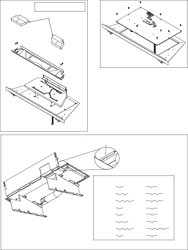
Note: The base refractory must be removed to access screws.
BASE REFRACTORY
Figure 3.6 Valve Assembly Removal
|
D. Burner Identification/Verification |
|
The burner may be accessed for identification and veri- |
|
fication purposes. This task should be performed by a |
|
qualified service technician. The base refractory, valve |
|
plate, refractory and grate do not need to be removed to |
|
access the burner assembly. The logs and fiber burner |
|
top need to be removed to access the burner. Disconnect |
|
the pilot from the burner before removal. See Figure 3.7 |
|
for burner identification chart. Notch patterns are located |
Figure 3.5 Base Refractory Removal |
on bottom side of burner. |
|
|
|
NOTCH LOCATION |
|
|
|
|
NG |
LP |
|
|
BOTTOM |
6000C |
|
|
BURNER |
6000CL |
|
|
|
|
|
||
|
|
6000CLX |
|
|
|
|
|
|
|
|
|
|
6000CBV |
|
|
|
|
8000C |
|
|
|
|
8000CL |
|
|
|
|
8000CLX |
|
|
|
|
8000CBV |
|
Figure 3.7 |
Burner Identification |
|
|
|
16 |
Heat & Glo • 6000CLX-IPI-S, 6000CLX-IPI-T, 8000CLX-S, 8000CLX-IPI-T • 2166-900 Rev. G • 12/09 |
|||
4 |
Getting Started |
Installer Guide |
|
||
|
|
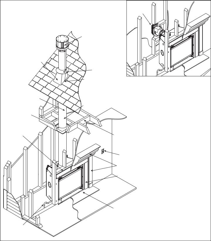
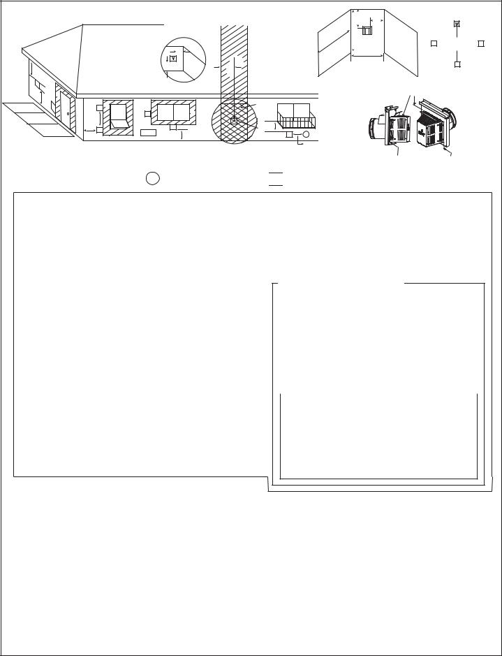
A. Typical Appliance System
NOTICE: Illustrations and photos reflect typical installations and are for design purposes only. Illustrations/diagrams are not drawn to scale. Actual product may vary from pictures in manual
Note: Dual venting configurations ARE NOT allowed. Appliance MUST be vented EITHER vertically OR horizontally.
NON-COMBUSTIBLE ROOF FLASHING
MAINTAINS MINIMUM CLEARANCE
AROUND PIPE (SECTION 10.G)
VENT PIPE (SECTIONS 7 and 8)
CEILING FIRESTOP ON FLOOR OF ATTIC (SECTION 8.C)
FRAMING/HEADER (SECTION 5.B)
HORIZONTAL
TERMINATION CAP (SECTION 10.L )
VERTICAL TERMINATION CAP (SECTION 10.I)
STORM COLLAR (SECTION 10.H)
VENT PIPE PENETRATES ROOF
PREFERABLY WITHOUT AFFECTING
ROOF RAFTERS (SECTION 8.C)
ATTIC INSULATION SHIELD (NOT SHOWN) MUST BE USED HERE TO KEEP INSULATION AWAY FROM VENT PIPE IF ATTIC IS INSULATED (SECTION 8.D)
FRAMING HEADED OFF IN CEILING JOISTS (SECTION 8.C)
OPTIONAL
WALL SWITCH SECTION 12.C.
MANTEL AND MANTEL LEG (SECTION 5.D)
SURROUND
HEARTH EXTENSION
GAS LINE (SECTION 11)
Figure 4.1 Typical System
Heat & Glo • 6000CLX-IPI-S, 6000CLX-IPI-T, 8000CLX-S, 8000CLX-IPI-T • 2166-900 Rev. G • 12/09 |
17 |
B. Design and Installation Considerations
Heat & Glo direct vent gas appliances are designed to operate with all combustion air siphoned from outside of the building and all exhaust gases expelled to the outside. No additional outside air source is required.
Installation MUST comply with local, regional, state and national codes and regulations. Consult insurance carrier, local building inspector, fire officials or authorities having jurisdiction over restrictions, installation inspection and permits.
Before installing, determine the following:
•Where the appliance is to be installed.
•The vent system configuration to be used.
•Gas supply piping requirements.
•Electrical wiring requirements.
•Framing and finishing details.
•Whether optional accessories—devices such as a fan, wall switch, or remote control—are desired.
Improper installation, adjustment, alteration, service or maintenance can cause injury or property damage. For assistance or additional information, consult a qualified service technician, service agency or your dealer.
C. Tools and Supplies Needed
Before beginning the installation be sure that the following tools and building supplies are available.
Tape measure |
Framing material |
Pliers |
High temperature caulking material |
Hammer |
Phillips screwdriver |
Gloves |
Framing square |
Voltmeter |
Electric drill and bits (1/4 in.) |
Plumb line |
Safety glasses |
Level |
Reciprocating saw |
Manometer |
Flat blade screwdriver |
Non-corrosive leak check solution
1/2 - 3/4 in. length, #6 or #8 Self-drilling screws One 1/4 in. female connection (for optional fan).
D. Inspect Appliance and Components
•Carefully remove the appliance and components from the packaging.
•The vent system components and decorative doors and fronts may be shipped in separate packages.
•If packaged separately, the log set and appliance grate must be installed.
•Report to your dealer any parts damaged in shipment, particularly the condition of the glass.
•Read all of the instructions before starting the installation. Follow these instructions carefully during the installation to ensure maximum safety and benefit.
WARNING! Risk of Fire or Explosion! Damaged parts could impair safe operation. DO NOT install damaged, incomplete or substitute components. Keep appliance dry.
Hearth & Home Technologies disclaims any responsibility for, and the warranty will be voided by, the following actions:
•Installation and use of any damaged appliance or vent system component.
•Modification of the appliance or vent system.
•Installation other than as instructed by Hearth & Home Technologies.
•Improper positioning of the gas logs or the glass door.
•Installation and/or use of any component part not approved by Hearth & Home Technologies.
Any such action may cause a fire hazard.
WARNING! Risk of Fire, Explosion or Electric Shock! DO NOT use this appliance if any part has been under water. Call a qualified service technician to inspect the appliance and to replace any part of the control system and/or gas control which has been under water.
18 |
Heat & Glo • 6000CLX-IPI-S, 6000CLX-IPI-T, 8000CLX-S, 8000CLX-IPI-T • 2166-900 Rev. G • 12/09 |
5 Framing and Clearances
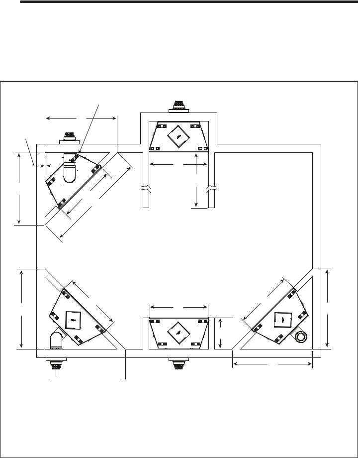
A. Selecting Appliance Location
When selecting a location for the appliance it is important to consider the required clearances to walls (see Figure 5.1).
WARNING! Risk of Fire or Burns! Provide adequate clearance around air openings and for service access.
Due to high temperatures, the appliance should be located out of traffic and away from furniture and draperies.
NOTICE: Illustrations reflect typical installations and are FOR DESIGN PURPOSES ONLY. Illustrations/diagrams are not drawn to scale. Actual installation may vary due to individual design preference.
NOTE: THE REAR STANDOFF MAY NEED
TO BE REMOVED WHEN VENTING AT 45º
A
 G
G

1/2 IN.
B
ALCOVE
INSTALLATION E
A
BC
TOP VENT
ONE 90º ELBOW
|
REAR VENT, |
|
|
|
HORIZONTAL TERMINATION |
REAR VENT |
|
|
TWO ELBOWS |
||
|
B |
NO ELBOWS |
|
D |
B |
||
|

 H
H  D
D
REAR VENT ONE ELBOW
B
D
F
D
|
|
A |
B |
C |
D |
E |
F |
G |
H |
|
6000 |
in. |
51 |
42 |
72 |
56-5/8 |
See Section D. |
22 |
17-3/4 |
8 |
|
mm |
1295 |
1067 |
1829 |
1438 |
Mantel Projections |
559 |
451 |
203 |
||
|
||||||||||
8000 |
in. |
55-7/8 |
49 |
79 |
61-1/2 |
See Section D. |
22 |
19-3/4 |
10 |
|
mm |
1419 |
1245 |
2007 |
1562 |
Mantel Projections |
559 |
502 |
254 |
||
|
Figure 5.1 Appliance Locations - 6000 Models
Heat & Glo • 6000CLX-IPI-S, 6000CLX-IPI-T, 8000CLX-S, 8000CLX-IPI-T • 2166-900 Rev. G • 12/09 |
19 |
B. Constructing the Appliance Chase
A chase is a vertical box-like structure built to enclose the gas appliance and/or its vent system. In cooler climates the vent should be enclosed inside the chase.
NOTICE: Treatment of ceiling firestops and wall shield firestops and construction of the chase may vary with the type of building. These instructions are not substitutes for the requirements of local building codes. Therefore, you MUST check local building codes to determine the requirements to these steps.
Chases should be constructed in the manner of all outside walls of the home to prevent cold air drafting problems. The chase should not break the outside building envelope in any manner.
Walls, ceiling, base plate and cantilever floor of the chase should be insulated. Vapor and air infiltration barriers should be installed in the chase as per regional codes for the rest of the home. Additionally, in regions where cold air infiltration may be an issue, the inside surfaces may be sheetrocked and taped for maximum air tightness.
To further prevent drafts, the wall shield and ceiling firestops should be caulked with high temperature caulk to seal gaps. Gas line holes and other openings should be caulked with high temperature caulk or stuffed with unfaced insulation. If the appliance is being installed on a cement surface, a layer of plywood may be placed underneath to prevent conducting cold up into the room.
C. Clearances
NOTICE: Install appliance on hard metal or wood surfaces extending full width and depth. DO NOT install directly on carpeting, vinyl, tile or any combustible material other than wood.
WARNING! Risk of Fire! Maintain specified air space clearances to appliance and vent pipe:
•Insulation and other materials must be secured to prevent accidental contact.
•The chase must be properly blocked to prevent blown insulation or other combustibles from entering and making contact with fireplace or chimney.
•Failure to maintain airspace may cause overheating and a fire.
A E
B |
|
J |
|
F |
|
C |
H |
D |
I |
G |
* MINIMUM FRAMING DIMENSIONS
|
|
|
A |
B |
C** |
D |
E |
F |
G |
H |
I |
J |
Models |
|
Rough |
Rough |
Rough |
Rough |
Clearance |
Combustible |
Combustible |
Behind |
Sides of |
Front of |
|
|
|
|
Opening |
Opening |
Opening |
Opening |
||||||
|
|
|
(Width) |
(Height) |
(Depth) |
(Width) |
to Ceiling |
Floor |
Flooring |
Appliance |
Appliance |
Appliance |
|
|
|
|
|
|
|
|
|
||||
6000 |
|
in. |
10 |
40-1/8 |
22 |
42 |
25 |
0 |
0 |
1/2 |
1/2 |
36 |
|
mm |
254 |
1019 |
559 |
1067 |
635 |
0 |
0 |
13 |
13 |
914 |
|
|
|
|||||||||||
8000 |
|
in. |
10 |
42-1/8 |
22 |
49 |
25 |
0 |
0 |
1/2 |
1/2 |
36 |
|
mm |
254 |
1019 |
559 |
1245 |
635 |
0 |
0 |
13 |
13 |
914 |
|
|
|
|||||||||||
* Adjust framing dimensions for interior sheathing (such as sheetrock) C** Add 12 inches for rear venting with one 90º elbow.
Figure 5.2 Clearances to Combustibles
20 |
Heat & Glo • 6000CLX-IPI-S, 6000CLX-IPI-T, 8000CLX-S, 8000CLX-IPI-T • 2166-900 Rev. G • 12/09 |
D. Mantel and Wall Projections
WARNING! Risk of Fire! Comply with all minimum clearances as specified. Framing or finishing material closer than the minimums listed must be constructed entirely of noncombustible materials (i.e., steel studs, concrete board, etc).
Combustible Mantels
TO CEILING
|
|
|
|
|
|
|
|
|
|
|
|
18 |
|
|
|
|
|
|
|
|
|
|||||||
|
|
|
|
|
|
|
|
|
|
|
|
12 |
|
|
|
|
|
|
|
|
|
|
|
|||||
|
|
|
|
|
|
|
|
|
|
|
|
|
|
|
|
|
|
|
|
|
|
|
||||||
|
|
|
|
|
|
|
|
10 |
11 |
|
|
|
|
|
|
|
|
|
|
|
|
|
|
|||||
|
|
|
|
|
|
|
|
|
|
|
|
|
|
|
|
|
|
|
|
|
|
32 |
||||||
|
|
|
|
|
|
|
|
9 |
|
|
|
|
|
|
|
|
|
|
|
|||||||||
|
|
|
|
|
|
|
|
|
|
|
|
|
|
|
|
|
|
|
|
|
|
|
|
|
|
|
||
8 |
|
|
|
|
|
|
|
|
|
|
|
|
|
|
25 |
|
|
|||||||||||
7 |
|
|
|
|
|
|
|
|
|
|
|
|
|
|
|
|
|
|
|
|
|
|
||||||
|
|
|
|
|
|
|
|
|
|
|
|
|
|
|
19 |
|
|
|
|
|||||||||
6 |
|
|
|
|
|
|
|
|
|
|
18 |
|
|
|
|
|
||||||||||||
5 |
|
|
|
|
|
|
|
|
|
|
17 |
|
|
|
|
|
|
|
|
|||||||||
4 |
|
|
|
|
|
|
|
|
|
|
|
|
|
16 |
|
|
|
|
|
|
|
|
|
|||||
3 |
|
|
|
|
|
|
|
|
|
|
|
15 |
|
|
|
|
|
|
|
|
|
|
|
|||||
|
|
|
|
|
|
|
|
|
|
|
|
|
|
|
|
|
|
|
|
|
|
|
||||||
|
|
|
|
|
|
|
|
|
|
|
|
|
|
|
|
|
|
|
|
|
|
|
|
|
|
|
|
|
14
13
12
2-1/2 11
10
5
MEASUREMENTS FROM
TOP EDGE OF THE OPENING
Note: All measurements in inches.
Note: Measurement is taken from top of the opening, NOT the top of the fireplace.
Figure 5.3 Minimum Vertical and Maximum Horizontal
Dimensions of Combustibles
Combustible Mantel Legs or Wall Projections
INTERIOR WALL
TOP VIEW
A B
FIREPLACE OPENING
MANTEL LEG OR WALL PROJECTIONS
If A minimum is ____, then B maximum is_____.
A |
Inches |
2-7/16 |
3-7/16 |
4-7/16 |
5-7/16 |
6-7/16 |
7-7/16 |
|
Millimeters |
62 |
87 |
113 |
138 |
164 |
189 |
||
|
||||||||
B |
Inches |
1 |
2 |
3 |
4 |
5 |
∞ |
|
Millimeters |
25 |
51 |
76 |
102 |
127 |
∞ |
Figure 5.4 Clearances to Mantel Legs or Wall Projections (Acceptable on both sides of opening.)
Heat & Glo • 6000CLX-IPI-S, 6000CLX-IPI-T, 8000CLX-S, 8000CLX-IPI-T • 2166-900 Rev. G • 12/09 |
21 |
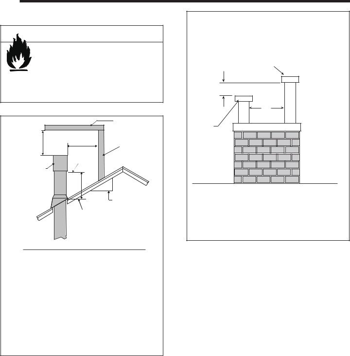
6 Termination Locations
A. Vent Termination Minimum Clearances
 WARNING
Fire Risk.
Maintain vent clearance to combustibles as specified.
• DO NOT pack air space with insulation or other materials.
Failure to keep insulation or other materials away from vent pipe may cause overheating and fire.
|
|
HORIZONTAL |
|
|
OVERHANG |
2 FT. |
20 INCHES MIN. |
VERTICAL |
MIN. |
|
|
|
WALL |
|
|
LOWEST |
|
|
|
|
|
DISCHARGE |
|
|
OPENING |
|
GAS DIRECT VENT |
|
|
TERMINATION CAP |
|
|
|
|
X |
|
|
12 |
|
|
ROOF PITCH |
|
|
IS X/ 12 |
|
H (MIN.) - MINIMUM HEIGHT FROM ROOF |
|
|
TO LOWEST DISCHARGE OPENING |
|
Roof Pitch |
|
H (Min.) Ft. |
Flat to 6/12...........................................................1.0* |
||
Over 6/12 to 7/12.................................................1.25* |
||
Over 7/12 to 8/12.................................................1.5* |
||
Over 8/12 to 9/12.................................................2.0* |
||
Over 9/12 to 10/12...............................................2.5 |
||
Over 10/12 to 11/12 .............................................3.25 |
||
Over 11/12 to 12/12 .............................................4.0 |
||
Over 12/12 to 14/12.............................................5.0 |
||
Over 14/12 to 16/12.............................................6.0 |
||
Over 16/12 to 18/12.............................................7.0 |
||
Over 18/12 to 20/12.............................................7.5 |
||
Over 20/12 to 21/12.............................................8.0 |
||
* 3 foot minimum in snow regions |
||
Figure 6.1 Minimum Height From Roof To Lowest Discharge |
||
Opening |
|
|
A |
B |
6 in. (minimum) up to 20 in. |
18 in. minimum |
152 mm/508 mm |
457 mm |
20 in. and over |
0 in. minimum |
Gas, Wood or Fuel Oil
Termination Cap
B
A*
Gas
Termination
Cap **
*If using decorative cap cover(s), this distance may need to be increased. Refer to the installation instructions supplied with the decorative cap cover.
**In a staggered installation with both gas and wood terminations, the wood termination cap must be higher than the gas termination cap.
Figure 6.2 Staggered Termination Caps
22 |
Heat & Glo • 6000CLX-IPI-S, 6000CLX-IPI-T, 8000CLX-S, 8000CLX-IPI-T • 2166-900 Rev. G • 12/09 |
|
|
|
E |
|
|
|
|
C |
|
|
A |
|
F |
|
|
|
|
|
|
|
|
|
|
V |
|
|
|
|
|
|
|
J |
B |
|
|
|
U.S |
|
|
|
|
|
|
|
|
||
|
V |
V |
B |
|
|
|
|
|
B |
(3 FT.) |
|
||||
|
|
|
V |
|
|
|
|
|
|
i |
|
|
|
|
|
|
|
|
|
|
|
|
|
|
D |
V |
V |
|
G |
M |
X |
|
|
|
A |
|
|
V |
|
|
|
|
|
|
|
|
H or i |
|
|
O |
|
|
|
V |
|
|
|
N |
|
|
|
||||
|
|
|
|
|
|
|||
|
P |
|
L |
|
|
|||
R |
|
|
|
V |
K |
Electrical |
K |
V |
|
|
|
|
Service |
|
|||
|
|
|
|
|
|
|
|
|
C
Q
V
(See Note 2)
Measure vertical clearances from this surface.
|
V |
= VENT TERMINAL |
X = AIR SUPPLY INLET |
|
A |
= |
12 inches................. |
clearances above grade, veranda, |
|
|
|
|
(See Note 1) |
porch, deck or balcony |
B |
= |
12 inches................. |
clearances to window or door |
|
|
|
|
|
that may be opened, or to perma- |
|
|
|
|
nently closed window. (Glass) |
C |
= |
18 inches................. |
vertical clearance to unventilated |
|
|
|
|
|
soffit or to ventilated soffit located |
|
|
|
|
above the terminal |
|
|
|
30 inches ................. |
for vinyl clad soffits and below |
|
|
|
|
electrical service |
D |
= |
9 inches................... |
clearance to outside corner |
|
E |
= |
6 inches................... |
clearance to inside corner |
|
F |
= |
3 ft. (Canada).......... |
not to be installed above a gas |
|
|
|
|
|
meter/regulator assembly within 3 |
|
|
|
|
feet (90 cm) horizontally from the |
|
|
|
|
center-line of the regulator |
G |
= |
3 ft........................... |
clearance to gas service regulator |
|
H |
= |
9 inches (U.S.A.) |
vent outlet |
|
|
||||
|
|
|
12 inches (Canada) clearance to non-mechanical |
|
|
|
|
(See Note 2) |
air supply inlet to building or the |
|
|
|
|
combustion air inlet to any other |
i |
= |
3 ft. (U.S.A.) |
appliance |
|
|
||||
|
|
|
6 ft. (Canada)........... |
clearance to a mechanical (pow- |
|
|
|
(See Note 2) |
ered) air supply inlet |
**a vent shall not terminate directly above a sidewalk or paved driveway which is located between two single family dwellings and serves both dwellings.
***only permitted if veranda, porch, deck or balcony is fully open on a minimum of 2 sides beneath the floor, or meets Note 2.
Note 1: On private property where termination is less than 7 feet above a sidewalk, driveway, deck, porch, veranda or balcony, use of a listed cap shield is suggested. (See vents components page)
Note 2: Termination in a covered alcove space (spaces open only on one side and with an overhang) are permitted with the dimensions specified for vinyl or non-vinyl siding and soffits. 1. There must be 3 feet minimum between termination caps. 2. All mechanical air intakes within 10 feet of a termination cap must be a minimum of 3 feet below the termination cap. 3. All gravity air intakes within 3 feet of a termination cap must be a minimum of 1 foot below the termination cap.
Figure 6.3 Minimum Clearances for Termination
Measure horizontal clearances from this surface.
 = AREA WHERE TERMINAL IS NOT PERMITTED
J** |
= |
7 ft.......................... |
clearance above paved |
|
|
(See Note 1) |
sidewalk or a paved driveway |
|
|
|
located on public property |
K |
= |
6 inches................. |
clearance from sides of electri- |
|
|
(See Note 5) |
cal service |
L |
= |
12 inches................ |
clearance above electrical |
|
|
(See Note 5) |
service |
Covered Alcove Applications
M*** = |
18 inches ............. |
clearance under veranda, porch, |
||||
|
|
|
|
deck, balcony or overhang |
||
|
|
42 inches |
......... vinyl |
|
|
|
N |
= |
6 inches ........... |
non-vinyl sidewalls |
|||
|
|
12 inches ......... |
vinyl sidewalls |
|||
O |
= |
18 inches ......... |
non-vinyl soffit and overhang |
|||
|
|
42 inches ......... |
vinyl soffit and overhang |
|||
P |
= |
8 ft. |
|
|
|
|
|
|
|
|
|
|
|
|
|
|
|
QMIN |
RMAX |
|
|
1 cap |
|
3 feet |
2 x Q ACTUAL |
|
|
|
2 caps |
|
6 feet |
1 x Q ACTUAL |
|
|
|
3 caps |
|
9 feet |
2/3 x Q ACTUAL |
|
|
|
4 caps |
|
12 feet |
1/2 x Q ACTUAL |
||
|
|
|
|
|
|
|
QMIN = # termination caps x 3 RMAX = (2 / # termination caps) x QACTUAL
Note 3: Local codes or regulations may require different clearances.
Note 4: Termination caps may be hot. Consider their proximity to doors or other traffic areas.
Note 5: Location of the vent termination must not interfere with access to the electrical service.
In the U.S and Canada: Vent system termination is NOT permitted in screened porches.
Vent system termination is permitted in porch areas with two or more sides open. You must follow all side walls, overhang and ground clearances as stated in the instructions.
Heat & Glo assumes no responsibility for the improper performance of the appliance when the venting system does not meet these requirements.
CAUTION: IF EXTERIOR WALLS ARE FINISHED WITH VINYL SIDING, IT IS SUGGESTED THAT A VINYL PROTECTOR KIT BE INSTALLED.
Heat & Glo • 6000CLX-IPI-S, 6000CLX-IPI-T, 8000CLX-S, 8000CLX-IPI-T • 2166-900 Rev. G • 12/09 |
23 |
7 Vent Information and Diagrams
A. Approved Pipe
This appliance is approved for use with Hearth & Home Technologies DVP or SLP venting systems. Refer to Section 16B for vent component information.
DO NOT mix pipe, fittings or joining methods from different manufacturers.
The pipe is tested to be run inside an enclosed wall. There is no requirement for inspection openings at each joint within the wall.
WARNING! Risk of Fire or Asphyxiation. This appliance requires a separate vent. DO NOT vent to a pipe serving a separate solid fuel burning appliance.
B. Vent Table Key
The abbreviations listed in this vent table key are used in the vent diagrams.
Symbol |
Description |
|
|
V1 |
First section (closest to appliance) of vertical length |
|
|
V2 |
Second section of vertical length |
|
|
H1 |
First section (closest to appliance) of horizontal length |
|
|
H2 |
Subsequent sections of horizontal length |
|
|
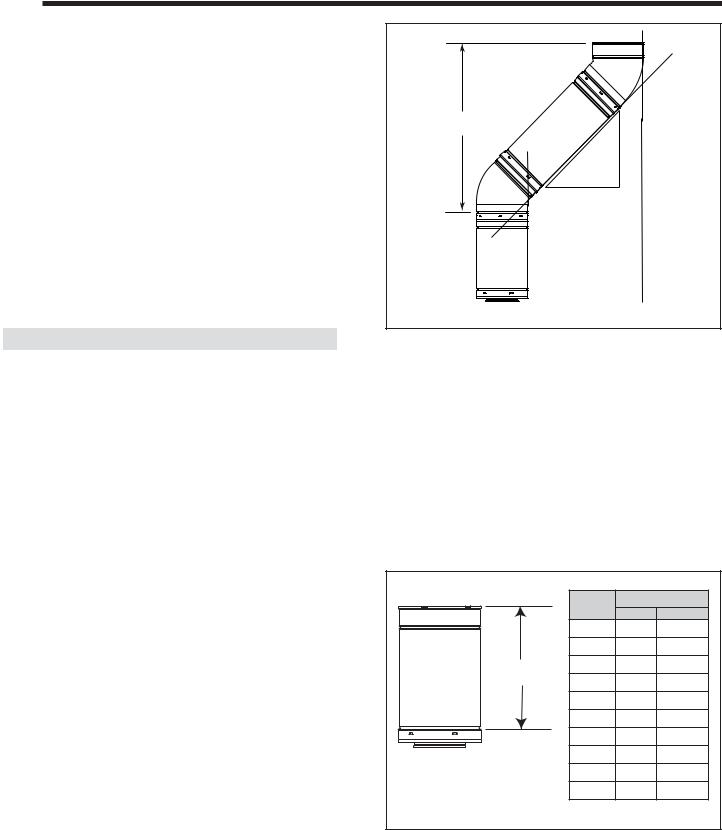
C. Use of Elbows
Diagonal runs have both vertical and horizontal vent aspects when calculating the effects. Use the rise for the vertical aspect and the run for the horizontal aspect (see Figure 7.1).
Two 45º elbows may be used in place of one 90º elbow. On 45º runs, one foot of diagonal is equal to 8-1/2 in. (216 mm) horizontal run and 8-1/2 in. (216 mm) vertical run. A length of straight pipe is allowed between two 45º elbows (see Figure 7.1).
Vertical |
|
in. |
|
|
|
|
|
. |
|
|
1/2-8 |
|
12 |
in |
|
|
8-1/2 in.
 Horizontal
Figure 7.1
D. Measuring Standards
Vertical and horizontal measurements listed in the vent diagrams were made using the following standards.
•Pipe measurements are shown using the effective length of pipe (see Figure 7.2).
•Horizontal terminations are measured to the outside mounting surface (flange of termination cap) (see Figure 6.3).
•Vertical terminations are measured to bottom of termination cap.
•Horizontal pipe installed level with no rise.
|
Pipe |
Effective Length |
|
|
Inches |
Millimeters |
|
|
|
||
|
DVP4 |
4 |
102 |
|
DVP6 |
6 |
152 |
Effective |
DVP12 |
12 |
305 |
Height/Length |
DVP24 |
24 |
610 |
|
|||
|
DVP36 |
36 |
914 |
|
DVP48 |
48 |
1219 |
|
DVP6A |
3 to 6 |
76 to 152 |
|
DVP12A |
3 to 12 |
76 to 305 |
|
DVP12MI |
3 to 12 |
76 to 305 |
|
DVP24MI |
3 to 24 |
76 to 610 |
Figure 7.2 DVP Pipe Effective Length |
|
|
|
24 |
Heat & Glo • 6000CLX-IPI-S, 6000CLX-IPI-T, 8000CLX-S, 8000CLX-IPI-T • 2166-900 Rev. G • 12/09 |
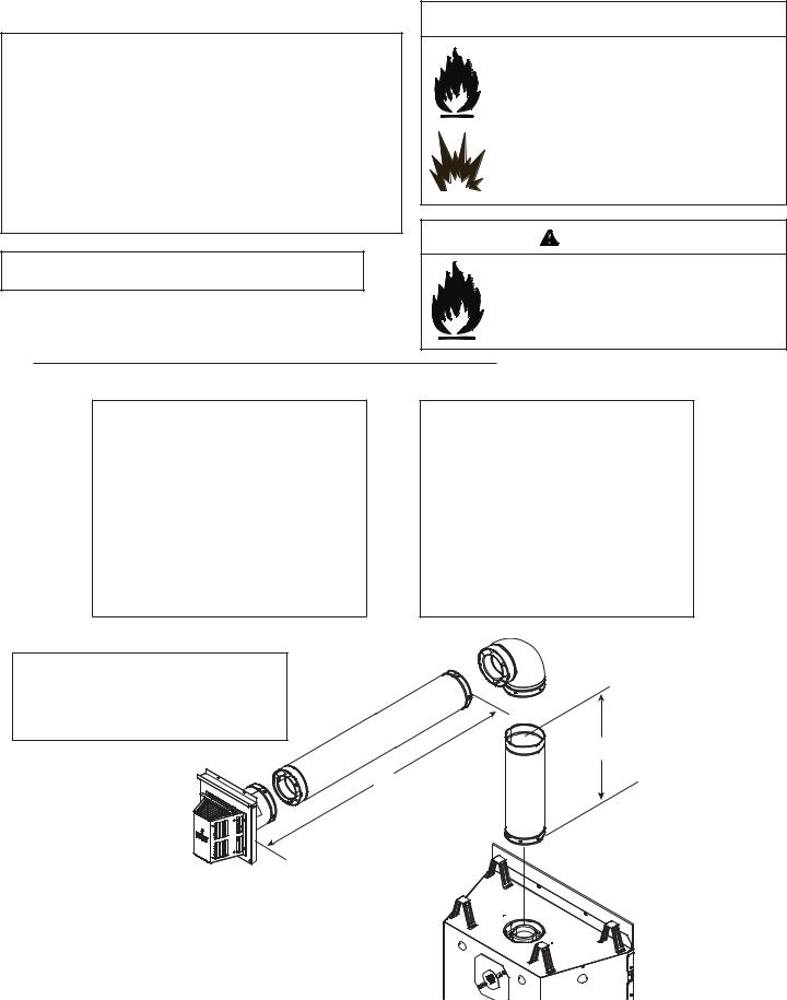
E. Vent Diagrams
Top Vent - Horizontal Termination
Note: The 6000/8000 series fireplaces can adapt to SLP series vent pipe, if desired.
When venting off the top of the unit, use a DVP-2SL adapter and a minimum 48 inch vertical section of SLP series vent pipe.
A DVP-SLP24 adapter may also be used with a 24 inch vertical section of SLP series vent pipe.
After the 48 inch vertical section, the venting table rules must be followed. The first 48 inch vertical section is NOT counted as part of the vertical components in the table. It is still counted as part of the overall maximum run. All venting table rules for the vent run must still be followed.
Example: DVP pipe 3 ft. min. vertical = 11 ft. max. horizontal SLP pipe 7 ft. min. vertical = 11 ft. max. horizontal
Top Vent - Horizontal Termination
One Elbow
 WARNING
Fire Risk. Explosion Risk.
Do NOT pack insulation or other combustibles between ceiling firestops.
•ALWAYS maintain specified clearances around venting and firestop systems.
•Install wall shield and ceiling firestops as specified.
Failure to keep insulation or other material away from vent pipe may cause fire.
WARNING
Fire Risk.
•When using DVP-HRC-SS and DVP-HRC-ZC- SS termination caps on top vented fireplaces, a 6 inch minimum vertical vent section is required before installing first elbow.
6000 MODELS
V1 Minimum |
H1 Maximum |
|||
Elbow only |
2 ft |
610 mm |
||
1 ft. |
|
305 mm |
3 ft. |
914 mm |
2 ft. |
|
610 mm |
6 ft. |
1.8 m |
3 ft. |
|
914 mm |
11 ft. |
3.4 m |
4 ft. |
|
1.2 m |
16 ft. |
4.9 m |
5 ft. |
|
1.5 m |
20 ft. |
6.1 m |
V1 |
+ H1 = 40 ft. (12.2 m) Maximum |
|||
|
H1 = 20 ft. (6.1 m) Maximum |
|||
8000 MODELS
V1 Minimum |
H1 Maximum |
|||
Elbow only |
1 ft |
305 mm |
||
1 ft. |
|
305 mm |
3 ft. |
914 mm |
2 ft. |
|
610 mm |
6 ft. |
1.8 m |
3 ft. |
|
914 mm |
11 ft. |
3.4 m |
4 ft. |
|
1.2 m |
16 ft. |
4.9 m |
5 ft. |
|
1.5 m |
20 ft. |
6.1 m |
V1 |
+ H1 = 40 ft. (12.2 m) Maximum |
|||
|
H1 = 20 ft. (6.1 m) Maximum |
|||
Note: For corner installations: A 6 inch (152 mm) section of straight pipe may need to
be attached to the appliance before a 90º elbow, to allow the vent pipe to clear the top
standoffs.
V1
H1
Figure 7.3
Heat & Glo • 6000CLX-IPI-S, 6000CLX-IPI-T, 8000CLX-S, 8000CLX-IPI-T • 2166-900 Rev. G • 12/09 |
25 |
 Loading...