

harman/kardon
DVD 29/230 Service Manual
Page 1 of 55
harman/kardon Service Manual
DVD 29/230
DVD player
TECHNICAL SPECIFICATIONS 2
TROUBLESHOOTING GUIDE 3
FRONT PANEL CONTROLS 4
FRONT PANEL DISPLAY 5
REAR PANEL CONNECTIONS 6
SETUP AND CONNECTIONS 7
Released EU2008 harman/kardon, Inc. Rev 0, 10/2008
250 Crossways Park Dr.
Woodbury, New York, 11797
CONTENTS
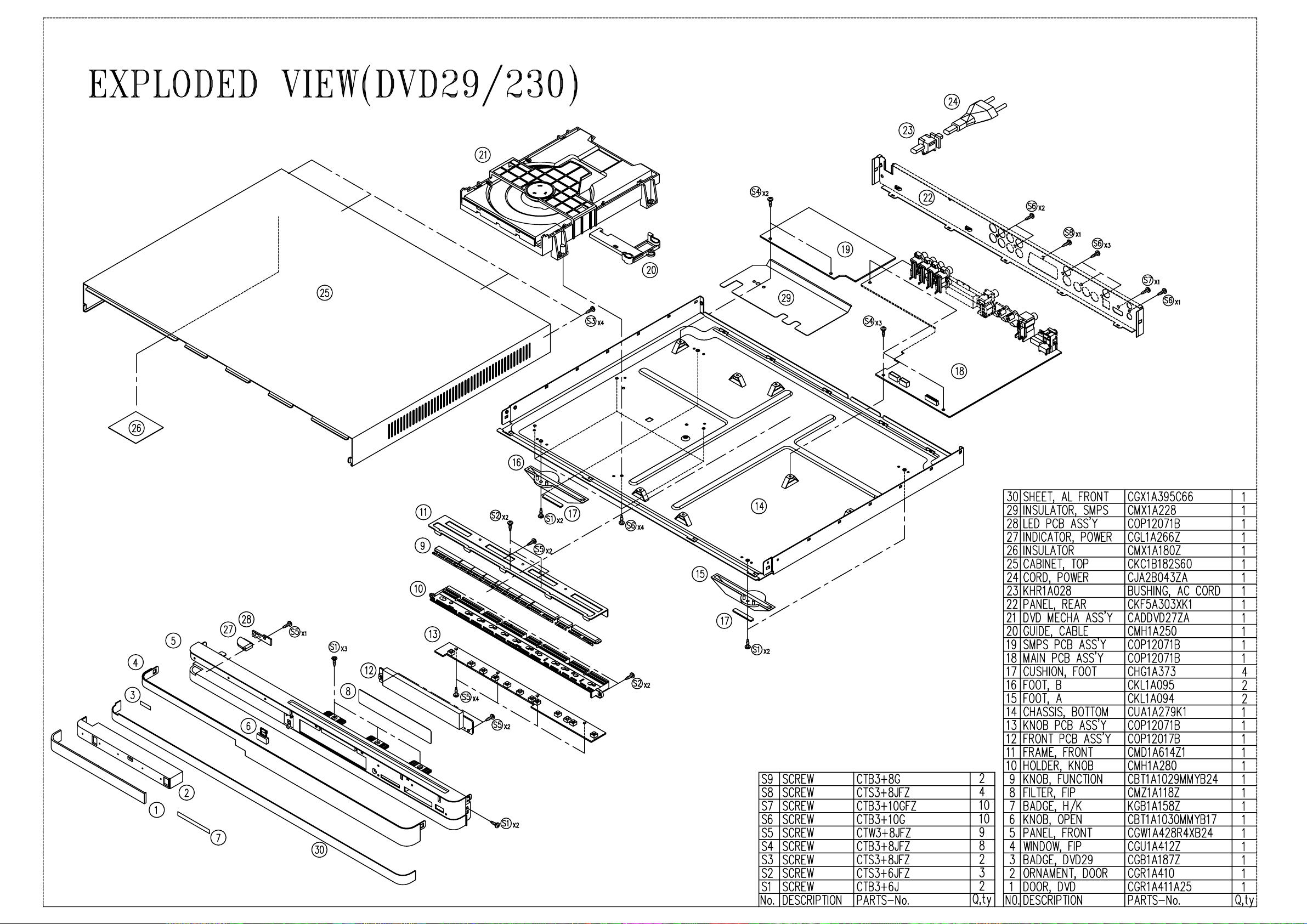
EXPLODED VIEW 9
PARTS LIST 10
SEMICONDUCTOR PINOUTS 24
WIRING DIAGRAM 50
SCHEMATIC DIAGRAMS 51

Technical Specifications
harman/kardon
DVD 29/230 Service Manual
Page 2 of 55
Applicable Disc: Disc formats: 5 inch (12 cm) or 3 inch (8 cm) DVD Video, DVD-Audio, Standard conforming DVD+RW, DVD+R, DVD-R,
DVD-RW, DivX, VCD, CD, CD-R, MP3,WMA, JPEG or CD-RW discs,
Regio code: DVD Movie disc with Code 2 or 0 only.
DVD-Layers: Single Side/Single Layer, Single Side/Dual Layer, Dual Side/Single Layer, Dual Side/Dual Layer
Audio formats: DVD-Audio MLP lossless, Linear PCM, MPEG, Windows Media
Dolby Digital or DTS Audio discs
Still-image format: JPEG
Video Signal System: PAL/NTSC
HDMI™Output: Video: 576p, 720p, 1080i
HDMI Version 1.0-compliant
HDCP Version 1.1-compliant
Composite Video Output: 1 V
S Video Output: Y/Luminance: 1 V
p-p/75 Ohms, sync negative polarity
p-p/75 Ohms, sync negative polarity
C/Chrominance: 0.286 V
p-p
Component Video Output: Y: 1 Vp-p/75 Ohms, sync negative polarity
Cr: 0.7 V
p-p/75 Ohms
Cb: 0.7 V
p-p/75 Ohms
Analog Audio Output: 2 Vrms max
Frequency Response: DVD (Linear PCM): 2Hz - 22kHz (48kHz sampling)
2Hz - 44kHz (96kHz sampling)
CD: 2Hz - 20kHz
Signal/Noise Ratio (SNR): 105 dB (A-weighted)
Dynamic Range: DVD: 100dB (18 Bit) / 105dB (20 Bit)
CD/DVD: 96dB (16 Bit)
THD/1kHz: DVD/CD: 0.0025 %
Wow & Flutter: Below Measurable Limits
AC Power: 100 - 240 V/50 ~ 60 Hz
Power Consumption: 1 Watts (Standby) /13 Watts (Max)
Dimensions (WxHxD): 440 x 50 x 285 mm
Weight: 4.0 kg
®
9,
ENGLISH
Depth measurement includes knobs and connectors.
Height measurement includes feet and chassis.
All specifications subject to change without notice.
Harman Kardon and Harman International are registered trademarks of Harman International Industries, Incorporated.
Manufactured under license from Dolby Laboratories. Dolby, Dolby Digital, ProLogic and the double-D symbol are trademarks of
Dolby Laboratories. Confidential.
Unpublished Work. © 1992-1997 Dolby Laboratories, Inc. All rights reserved.
Manufactured under license under U.S. Patent #: 5,451,942 & other U.S. and worldwide patents issued & pending.
DTS and DTS Digital Out are registered trademarks and the DTS logos and Symbol are trademarks of DTS, Inc. © 1996-2007 DTS, Inc. All Rights Reserved.
Microsoft, Windows and WMA are either registered trademarks or trademarks of Microsoft Corporation in the United States and/or other countries.
HDMI, the HDMI logo and High-Definition Multimedia Interface are trademarks or registered trademarks of HDMI Licensing LLC.
DivX, DivX Certified, and associated logos are trademarks of DivX Networks, Inc and are used under license.
This product incorporates copyright protection technology that is protected by method claims of certain U.S. patents and other intellectual property rights
owned by Macrovision Corporation and other rights owners. Use of this copyright protection technology must be authorized by Macrovision Corporation and
is intended for home and other limited viewing uses only unless otherwise authorized by Macrovision Corporation. Reverse engineering or diassembly is
prohibited.

Troubleshooting Guide
harman/kardon
DVD 29/230 Service Manual
Page 3 of 55
TroubleShooting Guide
Symptom Possible Cause Solution
Unit does not turn on • No AC power • Check AC power plug and make certain any switched
outlet is turned on.
Disc does not play • Disc loaded improperly • Load disc label-side up; align the disc with the guides and place
it in its proper position.
• Incorrect disc type
• Check to see that disc is CD, CD-R, CD-RW, DivX, VCD, MP3, WMA,
JPEG, DVD-R, DVD-RW, DVD+R, DVD+RW (standard conforming),
DVD-Audio or DVD-Video; other types will not play.
• Invalid Region Code
• Use Region 2 or Open Region (0) disc only.
• Rating is above parental preset
• Enter password to override or change rating settings.
No picture • Intermittent connections • Check all video connections.
• Wrong input • Check input selection of TV or receiver.
• Progressive Scan output selected • Use Progressive Scan mode only with compatible TV. If needed, press
the Progressive Scan/Interlaced Button
correct mode.
• Video Off feature active • Press Video Off Button
•
HDMI Output
video display that is not HDCP-compliant HDCP-compliant. Unplug the cable and select another audio and video
No sound • Intermittent connections • Check all audio connections.
• Incorrect digital audio selection • Check digital audio settings.
• DVD disc is in fast or slow mode • There is no audio playback on DVD discs during fast or slow modes.
• Surround receiver not compatible • Use analog audio outputs.
with 96kHz PCM audio
• DVD Audio disc is loaded without • Use
using analog audio connection
Picture is distorted or jumps during • MPEG-2 decoding • It is a normal artifact of DVD playback for pictures to jump or show
fast forward or reverse play some distortion during rapid play.
Some remote buttons do not operate • Function not permitted at this time • With most discs, some functions are not permitted at certain
during DVD play; prohibited symbol times (e.g.,Track Skip) or at all (e.g., direct audio track selection).
appears (see below)
The OSD menu is in a foreign language • Incorrect OSD language • Change the display language selection.
The symbol appears • Requested function not available at • Certain functions may be disabled by the DVD itself during
this time passages of a disc.
Picture is displayed in the • Incorrect match of aspect ratio settings • Change aspect ratio settings.
wrong aspect ratio to disc
Remote control inoperative • Weak batteries • Change both batteries.
• Sensor is blocked • Clear path to sensor or use optional outboard remote sensor.
Disc will not copy to VCR • Copy protection • Many DVDs are encoded with copy protection to prevent
Password not accepted • Incorrect password being used or • Stop play of disc. Press and hold the Clear Button
password has been forgotten blinks.This resets the password and all settings to their defaults.
is connected to a • The HDMI Outputmay not be used with video displays that are not
connection (see pages 11 through 12).
6-Channel Audio Outputs
copying to VCR.
Q
to reactivate video circuitry (see page 23)
L
to toggle to the
or Analog Audio Outputs.
until the display

Front Panel Controls
1
3
9 A B
4
5 6 7 8
2
harman/kardon
DVD 29/230 Service Manual
Page 4 of 55
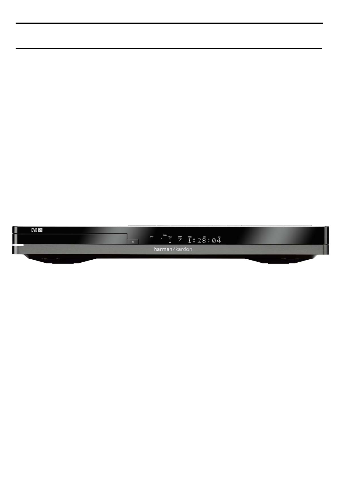
Main Information Display
1
Power On/Off (Standby)
2
Open/Close
3
Play/Pause
4
Setup
5
Stop
6
Skip/Search (Previous)
7
Skip/Search (Next)
8
Dimmer
9
Arrows left and right
A
Enter
B
Arrows up and down
Main Information Display: This display
delivers messages and status indications to help
you operate the DVD player.
1
Power On/Off (Standby): Press the button
once to turn the DVD player on, press it again to
put the unit in the Standby mode.
2
Open/Close: Press this button to open or
close the Disc Tray.
3
Play/Pause: Press to initiate playback or to
resume playback after Pause has been pressed.
Press this button to momentarily pause playback. To resume playback, press the button
again. If a DVD is playing, action will freeze and
a still picture will be displayed when the button
is pressed.
4
SETUP: Press this button to use the
DVD 29’s on-screen menu system to adjust the
player’s configuration settings. Note that the
A
Info Button
must be pressed to access the
DVD 29’s Player Information menu to obtain
detailed disc information, and to configure the
playback mode of the disc.
5
Stop: Press this button once to place the
disc in the Resume mode, which means that
playback will stop, but as long as the tray is not
opened or the disc changed, DVD playback will
continue from the same point on the disc when
the Play Button is pressed again. Resume will
also work if the unit was turned off. To stop a
disc and have play start from the beginning,
press the button twice.
6
Skip/Search (Previous): Press this button
to move backward through the music tracks on
a CD disc or the chapters on a DVD disc. Keep
the button pressed to search backwards at one
of the available speeds.
7
Skip/Search (Next): Press to move forward
through the music tracks on a CD or the
chapters on a DVD disc. Keep the button pressed
to search forwards at one of the available
speeds.
8
Dimmer: Press this button to reduce the
brightness of the Information Display by 50% or
to turn the display off completely in the
following order: FULL BRIGHTNESS ➔ HALF
BRIGHTNESS ➔ OFF ➔ FULL BRIGHTNESS.
9
ARROW buttons (M/N): Use to move the
cursor in the OSD.
A
ENTER: Press this button to activate a
setting or option.
B
ARROW buttons (K/L): Use to move
the cursor in the OSD.
Front Panel Information Display
A
L
B
C
D
E
F
G
H
I
J
K
M
N
O
harman/kardon
DVD 29/230 Service Manual
Page 5 of 55
ENGLISH
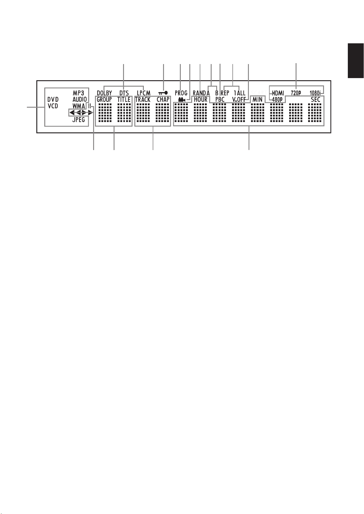
A Disc Type Indicators
B Playback-Mode Indicators
C Audio Bitstream Indicators
D Chapter/Track Number Indicators
E Time Indicators
A Disc Type Indicators: The CD, DVD, DVD-
Audio,VCD, MP3, WMA or JPEG indicator will
illuminate to show the type of disc currently
being played.
B Playback-Mode Indicators: These
indicators light to show the current playback
mode:
B
Lights when a disc is playing in the normal
mode
H
Lights when the disc is in the Fast Search
Forward mode. The on-screen banner display
indicates the selected speed (x2, x4, x8, x20,
x100).
1
Lights when the disc is paused.
G
Lights when the disc is in the Fast Search
Reverse mode.The on-screen banner display
indicates the selected speed (x2, x4, x8, x20,
x100).
C Audio Bitstream Indicators: When a
®
Digital, DTS®or linear PCM digital audio
Dolby
signal is present on the disc, one of these
indicators will light. DVD-Audio, MP3 and WMA
bitstreams will be indicated by the Disc Type
Indicator A.
D Chapter/Track Number Indicators: When
a DVD disc is playing, these two positions in the
display will show the current chapter. When a
CD disc is playing they will show the current
track number.
F Title Indicators
G V-OFF Indicator
H Repeat Indicators
I VCD Playback Control Indicator
J Random Indicator
E Time Indicators: These positions in the
indicator will show the running time of a DVD in
play.When a CD is playing, these indicators will
show the current track time, time remaining in
the current track, or the total remaining time on
the disc.
NOTE: The Indicators DEF will also display
text messages about the DVD’s status, including
LOADING when a disc is loading,
POWER OFF when the unit is turned off, and
DISC ERROR when a disc not compatible
with the DVD is put into the play position.
F Title Indicators: These two positions in the
display will show the current title number when
a DVD disc is playing.
G V-OFF Indicator: This indicator lights when
the unit's video output has been turned off by
pressing the V-OFF button on the remote
control.
H Repeat Indicators: These indicators light
when any of the Repeat functions are in use.
K A-B Repeat Indicator
L Program Indicator
M Angle Indicator
N Parental Lock Indicator
O Video Output Indicators
I VCD Playback Control Indicator: This
indicator lights when the playback control
function is turned on with VCDs.
J Random Indicator: This indicator lights
when the unit is in the Random Play mode.
K A-B Repeat Indicator: This indicator lights
when a specific passage for repeat playback has
been selected.
L Program Indicator: This indicator lights
when the programming functions are in use.
M Angle Indicator: This indicator blinks when
alternative viewing angles are available on the
DVD currently playing.
N Parental Lock Indicator: This indicator
lights when the parental-lock system is engaged
in order to prevent anyone from changing the
rating level without a code.
O Video Output Indicators: When the
DVD 29 is connected to a video display using
the HDMI Output
mation to the DVD 29 indicating the highest
video resolution it is capable of handling, and
the DVD 29 automatically sets the video output
to match it. That resolution is displayed here.
You may use the HD Mode Selector
manually select a lower video output resolution.
, the display sends infor-
to

Rear Panel Connections
2
3
5
6
8
9
0
7
B
A
1
4
harman/kardon
DVD 29/230 Service Manual
Page 6 of 55
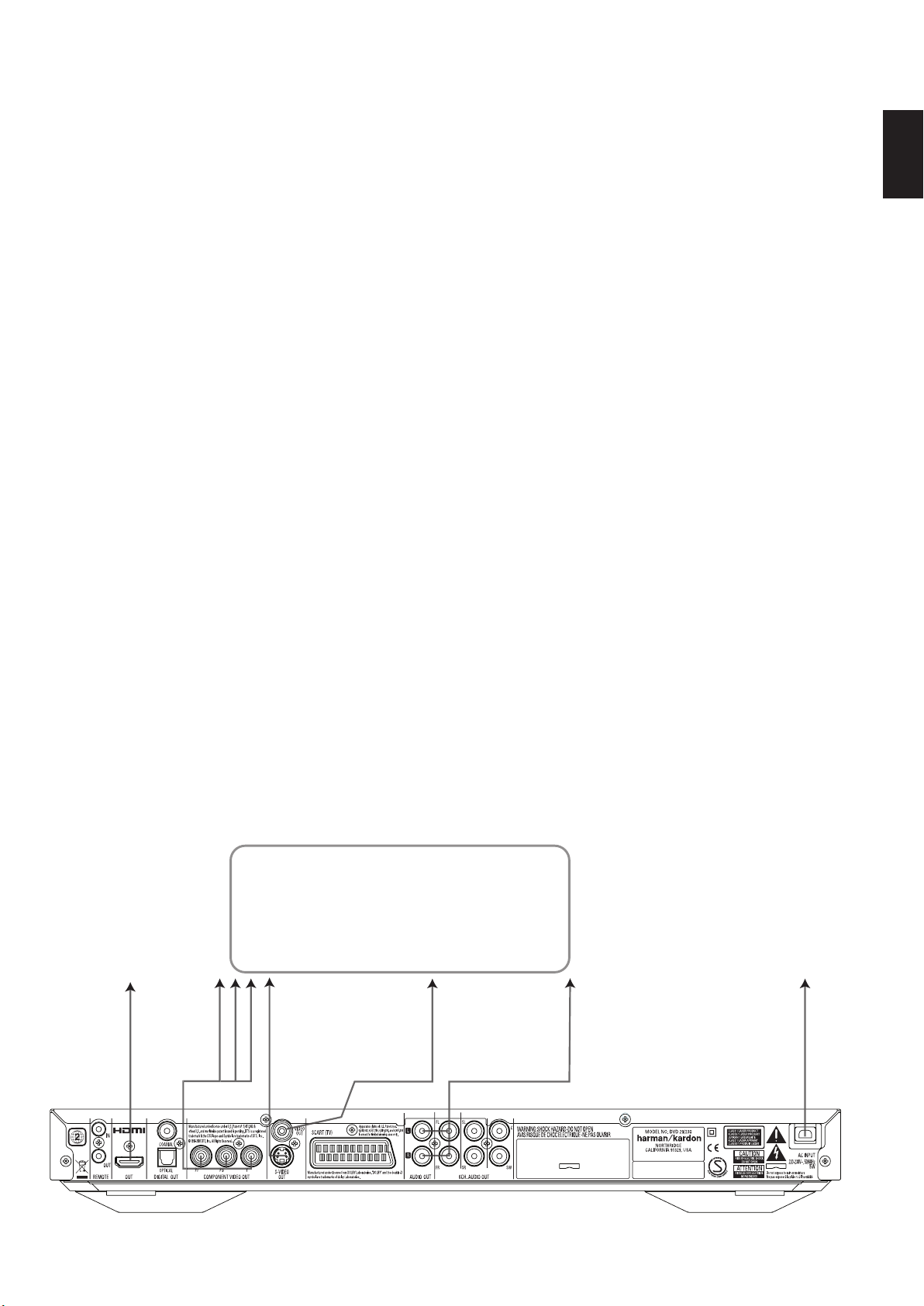
Optical Digital Output
Coaxial Digital Output
AC Power Cord
Composite Video Output
Optical Digital Output: Connect this jack
to the optical digital input of an A/V receiver or
surround processor for Dolby Digital, DTS or
PCM audio playback.
Coaxial Digital Output: Connect this jack
to the coaxial digital input of an A/V receiver or
surround processor for Dolby Digital, DTS or
PCM audio playback.
NOTE: The coaxial digital output should only be
connected to a digital input. Even though it is
the same RCA-type connector as standard
analog audio connections, DO NOT connect it to
a conventional analog input jack.
Connect either the Optical Digital Audio
Output
Output
input on your receiver or processor, but not both.
AC outlet. If the outlet is controlled by a switch,
make certain that it is in the ON position.
jack to the video input on a television or video
projector, or to a video input on an A/V receiver
or processor if you are using that type of device
for video input switching.
S-Video input on a television or video projector,
or to an S-Video input on an A/V receiver or
processor if you are using that type of device for
S-Video input switching.
puts carry the component video signals for
connection to display monitors with component
video inputs. For standard analog TV's or
projectors with inputs marked Y/Pr/Pb or
Y/Cr/Cb, connect these outputs to the corresponding inputs. If you have a high-definition television or projector that is compatible with high
scan rate progressive video, connect these jacks
to the “HD Component” inputs. Note that if you
are using a progressive scan display device, then
”Progressive” must be selected in the Video Setup Menu in order to take advantage of the
progressive scan circuitry. See page 19 for more
information on progressive scan video.
or the Coaxial Digital Audio
to a corresponding digital audio
AC Power Cord: Connect this plug to an
Composite Video Output: Connect this
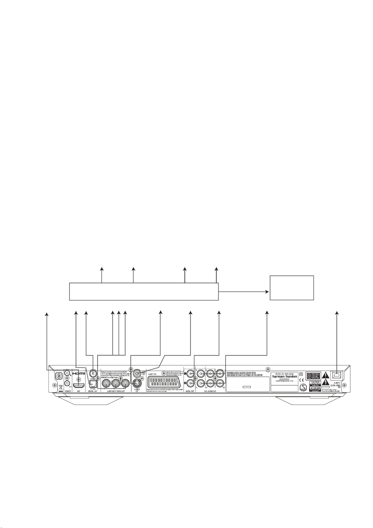
S-Video Output: Connect this jack to the
Component Video Outputs: These out-
S-Video Output
Component Video Outputs
Scart TV Output
Remote Control Output
IMPORTANT: These jacks should NOT be
connected to standard composite video inputs.
SCART OUT (TV): If your TV has a SCART
socket, you can connect a SCART cable to your
TV and to your DVD Player for improved video
quality.The SCART cable carries both audio and
video.You can select Composite Video or RGB
video for that SCART connector’s video output
signal.
Remote Control Output: Connect this
jack to the infrared (IR) input jack of another
compatible Harman Kardon remote controlled
product to have the built-in Remote Sensor on
the DVD provide IR signals to other compatible
products.
Remote Control Input: Connect the
output of a remote infrared sensor, or the
remote control output of another compatible
Harman Kardon product, to this jack.This will
enable the remote control to operate even when
the front panel Remote Sensor on the DVD is
blocked.This jack may also be used with
compatible IR remote control-based automation
systems.
Analog Audio Output: Connect these
jacks to an audio input on an A/V receiver or
surround processor for analog audio playback.
HDMI Output: If you have an HDMI-compatible receiver or video display device, connect
this output to an HDMI input on the receiver or
video display for the highest-quality uncompressed digital audio and video available. Even if
your receiver is not capable of processing audio
in the HDMI format, you may still experience the
superb reproduction of HDMI video.
If your video display has a DVI input, you may
use an optional HDMI-to-DVI cable or adapter
for the connection to the display. In all cases, the
video display must be HDCP-compliant in order
to use the HDMI output. For best results, we do
not recommend HDMI connections in excess of
ten feet.
Remote Control Input
Analog Audio Output
HDMI Output
6-Channel Audio Outputs
The following audio formats may be output via
the HDMI connection:
Audio CD – 2-Channel PCM or 5.1-channel DTS
DVD-Audio – 2-Channel PCM
DVD-Video – Up to 5.1-channel Dolby Digital or
DTS
Note: To hear the high-resolution surround
sound recorded on DVD-Audio discs, you need
to connect the 6-Channel Audio Outputs
to the corresponding input jacks on your receiver
or processor. These formats are not output digitally.
6-Channel Audio Outputs: Connect these
outputs to the matching 6-channel analog audio
inputs on your receiver or surround sound
processor. This connection is required to listen to
the multichannel tracks on DVD-Audio discs. If
the disc also contains a linear PCM, Dolby
Digital or DTS track, you may listen to it using
the HDMI
Audio Output
Outputs
Note: You’ll find more details about all
Audio/Video connections under Setup and
Connections on the following pages.
, Optical or Coaxial Dgital
or the Analog Audio
.
Setup and Connections
TV
E
To Y (green)/
Pb (blue)/
Pr (red)
component
video
connectors
To HDMI
or DVI
port on TV
To S-video
input
connectors
on the TV
To analog audio
input connectors
(red/white) on the TV
To video
input
connectors
(yellow)
on the TV
To power outlet
(AC 230V/50Hz)
D
C
B
A
harman/kardon
DVD 29/230 Service Manual
Page 7 of 55
Before connecting your DVD 29, please:
■ Ensure that the power switch of this unit and
other equipment to be connected is set to off
before commencing connection.
For the best quality, if your receiver or processor
and/or video display are HDMI-capable, we recommend using the HDMI output. With a single
cable connection between components, HDMI is
able to deliver uncompressed high-definition
digital video and digital audio programming.
Note: If your video display has a DVI input, you
may use an optional HDMI-to-DVI cable or
adapter for the connection to the display. In all
cases, the video display must be HDCP-compliant in order to use the HDMI output.
If your equipment is not HDMI-ready, we
recommend the use of component video for
higher quality pictures.
If you are using a television or video display that
is compatible with high-resolution 576P video
signals, make sure to use the input jacks on the
video display marked “HD Component,” if available.Also, make sure to configure the display’s
input settings for use with “576P” video signals.
You will also need to change the scan type in
the DVD 29’s Video Setup menu from
“Interlaced” to “Progressive.” See page 19.
The Video output (yellow) combines the complete video signal (composite) and sends it to
the TV (or to the AV Receiver) by one line only.
Use the Video output, when your TV set is
equipped with a Video input jack only.
The S (separate) video output connector separates the color (C) and luminance (Y) signals
■ Do not block ventilation holes of any of the
equipment and arrange them so that air can
circulate freely.
■ Read through the instructions before
connecting other equipment.
before transmitting them to the TV set in order
to achieve a sharper picture. Use the S-video
cable when connecting the player to a TV
equipped with an S-video inputfor improved
picture clarity. Never connect both outputs,
Video and S-Video, to your TV or AV Receiver,
only one of them.
Most European TV´s are equipped with SCART
connectors rather than with a normal video
input (yellow cinch). In that case the SCART
connection should be used, providing the audio
signal too. Separate analog audio connections to
TV are needed only if your TV is connected to
the video or S-video output.
You may also use the standard S-video or
composite video connection if your TV does not
have component video inputs.The component
and S-video outputs are not available
simultaneously.
• Modern audio/video receivers are capable of
connection to several video source devices,
such as the DVD 29 and a VCR, cable
television set-top box, HDTV tuner or other
device.The receiver is equipped with video
monitor outputs for connection to your television, projector or plasma display. As you select
any input source device, the receiver selects
the correct video input and routes it to the
correct video monitor output to your television. It is recommended that you connect one
■ Ensure that you observe the color coding
when connecting audio and video cables.
ENGLISH
of the video outputs from the DVD 29 to the
corresponding input on your receiver to
simplify operation of your home entertainment
system. Refer to the owner’s guide for your
receiver for more information.
• If your receiver is capable of multiroom opera-
tion, it is recommended that you connect both
the component (or HDMI) and composite
video outputs of the DVD 29 to the receiver.
This enables the highest-quality picture (component video) for viewing in the main listening
room, while enabling the multiroom system, if
it is video-capable, to distribute the composite
video signal to the remote zone. Consult the
owner’s guide for your receiver to determine
whether it has video multiroom capability.
Connecting to a TV Only
When using the DVD 29 with a television but no
audio receiver or processor, connect it as follows.
Make the Analog Audio Connection A and
one of the Video Connections (Composite
Video B, S-Video C, Component Video
D). If your television or video display is HDMI-
capable, you only need to make the HDMI E
connection, as it handles both audio and video.
Remember to plug in the power cord.
Setup and Connections
EFGHDCBA
To Y (green)/
Pb (blue)/
Pr (red)
component
video
connectors
To S-video
input
connectors
To coaxial
digital
audio
input
connectors
To optical
digital
audio
input
connectors
To analog audio
input connectors
(red/white)
on the TV
or receiver
(see above)
To 6-channel
analog audio
inputs on
receiver
To video
input
connectors
(yellow)
To power outlet
(AC 230V/50Hz)
Dolby Digital/DTS A/V Receiver or Processor
Front Speakers
(Left/Right)
Surround Speakers
(Left/Right)
Center
Speaker
Subwoofer
HDMI, DVI, Component,
S-video and/or
Composite video
monitor outputs
TV
To
HDMI
or DVI
port
harman/kardon
DVD 29/230 Service Manual
Page 8 of 55
Connecting to a Receiver/Amplifier
With a Dolby Digital or DTS
Decoder
One of the major advantages of the DVD format
is its ability to use a variety of digital audio formats for the ultimate in sonic performance.
However, in order to enjoy the benefits of digital
audio, you must use a receiver or processor that
has digital audio decoding capabilities and make
an optical or coaxial digital audio connection
between the DVD 29 and your home theater
system. This simple connection is made as shown
below with an optional coax or optical cable.
Only one of these connections is required, and
both should not be made at the same time.
In order to take advantage of the high-resolution
DVD-Audio output of the DVD 29, you must
connect the 6-Channel Audio Outputs
the matching 6-channel inputs on your receiver
or processor.
NOTES FOR ANALOG AUDIO:
• If you wish to use the DVD 29 as the input for
a multiroom system, the Analog Audio
Outputs
should be connected to the
standard analog left/right DVD or CD inputs on
your digital receiver or processor.
• The connection from the Analog Audio
Outputs
to the TV is optional.
to
• When the audio signal is to be fed to an
analog receiver rather than to the TV, connect
the Analog Audio Outputs
to any analog
audio inputs on your receiver or processor.
• The analog audio connection should also be
made if you wish to play high-resolution 96kHz
PCM audio discs where your receiver does not
support 96kHz processing.
NOTES ON VIDEO:
■ Note:With multiple video sources, your
Audio/Video device can be used for selecting
the video signal and routing it to the TV.
Connect the video or S-video output of the
DVD player (whatever is provided with your
device) to the video or S-video input on your
device and the video/S-video output of this
device to your TV. For more details, see the
manual of your Audio/Video amplifier/receiver.
■ Note for Analog Audio: The connection from
Audio Out to the TV is optional only. Normally
you´ll hear the sound from your AV-system´s
speakers, so the TV volume should be
completely turned down. If you plan to use
your DVD player also without having to turn
on your complete system, this connection
must exist, then you can turn up the TV´s
volume as needed.
Connecting to a Receiver
When using the DVD 29 with an audio/video
receiver or processor, connect it as follows. First,
make one of the video connections (Composite
Video C, S-Video D, Component Video E
or HDMI H) to the video input jacks on the A/V
receiver, and then connect the receiver’s video
monitor output to the TV. In addition, to benefit
from the high-resolution surround sound formats
recorded on DVD-Audio discs, which are not output via the HDMI connection, you will need to
make the 6-Channel Audio Connection A to
your receiver or processor.
Second, if your receiver or processor is not HDMIcapable, make either the Optical Digital Audio
Connection G or the Coaxial Digital Audio
Connection F, to the receiver or processor.
IMPORTANT NOTE: Make certain that any
device being connected, including the DVD 29,
your receiver or processor and your TV or video
display, is turned off whenever you make
connections between products.
Important Notes on SCART and RGB
format:
■ Your DVD is equipped with a SCART connector for direct connection to the TV.
■ The SCART connector provides the video
signal as well as audio (stereo L/R) signals.
■ The SCART connector for the TV provides the
composite video signal or the direct RGB
signal, delivering the best video performance
possible, selectable in the Setup menu.
To view RGB video on your TV, the RGB
compatible SCART connector on the TV must
be used and the DVD´s TV SCART connector
must be set to ”RGB”.
Note that with RGB video the color intensity
cannot be adjusted with most TVs.
■ When the RGB video signal is used, DVD´s
recorded with the NTSC format (with regional
code 0 or 2) can be viewed even on nonNTSC compatible TVs.
harman/kardon
DVD 29/230 Service Manual
Page 9 of 55

DVD 29/230 ELECTRICAL PARTS LIST
harman/kardon
DVD 29/230 Service Manual
Page 10 of 55
POS PART NUMBER PART NAME COMMENTS
CHE154 CLAMPER , ARM
CPS1A765 PAD , CENTER DMC250
CPS2A793 PAD , SNOW L
CPS2A794 PAD, SNOW R
CQXDVD29/230 INSTRUCTION MANUAL ASS'Y
CARTDVD29/230 REMOCON TRANSMITTER ASS'Y
CJS0I006Z CABLE, S-VHS(1.5M) Y, C
CJS4S004Z CORD , PIN(3P,W/R/Y)
CJS8T001Z CABLE, HDMI(2M) CBADV-005-2
CJS9D002Z CORD , JACK(MONO) 1200MM
CQX1A1294Y MANUAL , INSTRUCTION DVD29
CGR1A411ZA DVD DOOR ASS'Y(DMC250) DMC250
CGR1A410 ORNAMENT , DOOR
CGR1A411A25 DOOR , DVD
CGWDVD29/230 FRONT PANEL ASS'Y
CBT2A1029TA DVD29/230 FUNCTION KNOB ASS'Y
CBT2A1029MMTB24 KNOB , FUNCTION DVD29
CMH2A280 HOLDER , KNOB
CGB1A158Y BADGE , FRONT HARMAN/KARDON
CGB1A187Y BADGE , DVD29
CGL1A266Y INDICATOR , POWER DVD29
CGW3A428TA FRONT SUB ASS'Y
CBT1A1030MMYB17 KNOB , OPEN DVD29/230
CGU2A412A25Z WINDOW , FIP DVD29/230
CGW3A428R4XB24 PANEL , FRONT DVD29/230
CGX2A395C66 SHEET , AL FRONT DVD49/230
CHG1A305 CUSHION , SUPPORT
CMC1A341 PLATE , EARTH DMC250
CMD1A655 FRAME , FRONT
CMD2A682 BRACKET , HOLDER
CMZ1A118Z FILTER , FIP
CTB3+10JR SCREW
CTB3+8JR SCREW
CTS3+8JFZR SCREW
CWC4F2A07A080B CABLE , CARD(7P, 80mm, B TYPE)
CWC4F2A15A300B CABLE, CARD(15P, 300mm, B TYPE)
C8AAK81 BOND , LOCK
CKC1A182S60 CABINET , TOP DVD29
CMX1A180Z INSULATOR
CTB3+8JFZR SCREW
CTS3+8JFZR SCREW
CUADVD29/230 BOTTOM CHASSIS ASS'Y
CADDVD29/230ZA DVD MECHANISM ASS'Y
CADSDL003YA LOADER ASS'Y
CMH1A250 GUIDE, CABLE
CWB1B905250EE WIRE ASS'Y(5PIN, 250mm) 12PIN, 250MM, AWG#26
CWB5A906250SE WIRE ASS'Y(6PIN, 250mm) 12PIN, 240MM, AWG#28
CWC4G2A24G400B CABLE , CARD(24P, 400mm, B TYPE)
CHD1A055R SCREW , SPECIAL
CHG1A373 CUSHION , FOOT AVR350
CJA2B043ZA CORD , POWER(EUR) QDR-7100CC
CKF11A303VK1 PANEL , REAR DVD29/230
CKL1A098 FOOT , L
CKL1A099 FOOT , R
CMX2A228 INSULATOR , SMPS DVD29
COP12017B DVD29/230 MAIN PCB ASS'Y
CN11 CJP24GA195ZM SMT FFC/FPC WAFER(0.5MM PITCH) 52559-2472 (PB FREE)
C100 CCUS1H104KC CAP , CHIP 0.1UF 50V K
C101 CCUS1H104KC CAP , CHIP 0.1UF 50V K
C102 CCUS1H104KC CAP , CHIP 0.1UF 50V K
C103 CCUS1H104KC CAP , CHIP 0.1UF 50V K
C104 CCUS1H104KC CAP , CHIP 0.1UF 50V K
C106 CCUS1H104KC CAP , CHIP 0.1UF 50V K
C107 CCUS1H104KC CAP , CHIP 0.1UF 50V K
C110 CCUS1H104KC CAP , CHIP 0.1UF 50V K
C112 CCUS1H104KC CAP , CHIP 0.1UF 50V K
C113 CCUS1H104KC CAP , CHIP 0.1UF 50V K

POS PART NUMBER PART NAME COMMENTS
harman/kardon
DVD 29/230 Service Manual
Page 11 of 55
C115 CCUS1H104KC CAP , CHIP 0.1UF 50V K
C117 CCUS1H104KC CAP , CHIP 0.1UF 50V K
C120 CCUS1H104KC CAP , CHIP 0.1UF 50V K
C122 CCUS1H104KC CAP , CHIP 0.1UF 50V K
C124 CCUS1H104KC CAP , CHIP 0.1UF 50V K
C126 CCUS1H104KC CAP , CHIP 0.1UF 50V K
C127 CCUS1H104KC CAP , CHIP 0.1UF 50V K
C129 CCUS1H104KC CAP , CHIP 0.1UF 50V K
C146 CCUS1H104KC CAP , CHIP 0.1UF 50V K
C156 CCUS1H180JA CAP , CHIP(18PF/50V) 18PF 50V J
C157 CCUS1H330JA CAP , CHIP 33PF 50V J
C158 CCUS1H330JA CAP , CHIP 33PF 50V J
C159 CCUS1H562KC CAP , CHIP CERAMIC(1608, 5600p) 5600PF 50V K
C160 CCUS1H562KC CAP , CHIP CERAMIC(1608, 5600p) 5600PF 50V K
C161 CCUS1H562KC CAP , CHIP CERAMIC(1608, 5600p) 5600PF 50V K
C163 CCUS1H471JA CAP , CHIP 470PF 50V J
C164 CCUS1H104KC CAP , CHIP 0.1UF 50V K
C165 CCUS1H104KC CAP , CHIP 0.1UF 50V K
C166 CCUS1H102KC CAP , CHIP 1000PF 50V K
C167 CCUS1H102KC CAP , CHIP 1000PF 50V K
C168 CCUS1H102KC CAP , CHIP 1000PF 50V K
C169 CCUS1H102KC CAP , CHIP 1000PF 50V K
C170 CCUS1H102KC CAP , CHIP 1000PF 50V K
C172 CCUS1H102KC CAP , CHIP 1000PF 50V K
C173 CCUS1H102KC CAP , CHIP 1000PF 50V K
C174 CCUS1H333KC CAP , CHIP 0.033UF 50V K
C175 CCUS1H104KC CAP , CHIP 0.1UF 50V K
C176 CCUS1H102KC CAP , CHIP 1000PF 50V K
C178 CCUS1H104KC CAP , CHIP 0.1UF 50V K
C179 CCUS1H104KC CAP , CHIP 0.1UF 50V K
C180 CCUS1H104KC CAP , CHIP 0.1UF 50V K
C181 CCUS1H104KC CAP , CHIP 0.1UF 50V K
C183 CCUS1H104KC CAP , CHIP 0.1UF 50V K
C185 CCUS1H104KC CAP , CHIP 0.1UF 50V K
C186 CCUS1H104KC CAP , CHIP 0.1UF 50V K
C187 CCUS1H104KC CAP , CHIP 0.1UF 50V K
C188 CCUS1H104KC CAP , CHIP 0.1UF 50V K
C189 CCUS1H104KC CAP , CHIP 0.1UF 50V K
C190 CCUS1H104KC CAP , CHIP 0.1UF 50V K
C191 CCUS1H104KC CAP , CHIP 0.1UF 50V K
C192 CCUS1H104KC CAP , CHIP 0.1UF 50V K
C193 CCUS1H104KC CAP , CHIP 0.1UF 50V K
C194 CCUS1H104KC CAP , CHIP 0.1UF 50V K
C195 CCUS1H104KC CAP , CHIP 0.1UF 50V K
C196 CCUS1H104KC CAP , CHIP 0.1UF 50V K
C197 CCUS1H104KC CAP , CHIP 0.1UF 50V K
C199 CCUS1H104KC CAP , CHIP 0.1UF 50V K
C200 CCUS1H104KC CAP , CHIP 0.1UF 50V K
C201 CCUS1H104KC CAP , CHIP 0.1UF 50V K
C204 CCUS1H104KC CAP , CHIP 0.1UF 50V K
C205 CCUS1H104KC CAP , CHIP 0.1UF 50V K
C207 CCUS1H272KC CAP , CHIP 2700PF 50V K
C208 CCUS1H102KC CAP , CHIP 1000PF 50V K
C209 CCUS1H273KC CAP , CHIP 0.027UF 50V K
C210 CCUS1H102KC CAP , CHIP 1000PF 50V K
C214 CCUS1H104KC CAP , CHIP 0.1UF 50V K
C215 CCUS1H561JA CAP , CHIP 560PF 50V J
C217 CCUS1H273KC CAP , CHIP 0.027UF 50V K
C218 CCUS1H104KC CAP , CHIP 0.1UF 50V K
C220 CCUS1H104KC CAP , CHIP 0.1UF 50V K
C222 CCUS1H104KC CAP , CHIP 0.1UF 50V K
C225 CCUS1H104KC CAP , CHIP 0.1UF 50V K
C227 CCUS1H104KC CAP , CHIP 0.1UF 50V K
C228 CCUS1H222KC CAP , CHIP 2200PF 50V K
C229 CCUS1H222KC CAP , CHIP 2200PF 50V K
C230 CCUS1H222KC CAP , CHIP 2200PF 50V K
C231 CCUS1H222KC CAP , CHIP 2200PF 50V K
C232 CCUS1H330JA CAP , CHIP 33PF 50V J
C240 CCUS1H104KC CAP , CHIP 0.1UF 50V K

POS PART NUMBER PART NAME COMMENTS
harman/kardon
DVD 29/230 Service Manual
Page 12 of 55
C242 CCUS1H104KC CAP , CHIP 0.1UF 50V K
C244 CCUS1H104KC CAP , CHIP 0.1UF 50V K
C245 CCUS1H104KC CAP , CHIP 0.1UF 50V K
C247 CCUS1H104KC CAP , CHIP 0.1UF 50V K
C249 CCUS1H150JA CAP , CHIP(15PF/50V) 15PF 50V J
C250 CCUS1H150JA CAP , CHIP(15PF/50V) 15PF 50V J
C252 CCUS1H104KC CAP , CHIP 0.1UF 50V K
C253 CCUS1H104KC CAP , CHIP 0.1UF 50V K
C254 CCUS1H272KC CAP , CHIP 2700PF 50V K
C255 CCUS1H104KC CAP , CHIP 0.1UF 50V K
C256 CCUS1H104KC CAP , CHIP 0.1UF 50V K
C257 CCUS1H104KC CAP , CHIP 0.1UF 50V K
C260 CCUS1H104KC CAP , CHIP 0.1UF 50V K
C261 CCUS1H104KC CAP , CHIP 0.1UF 50V K
C262 CCUS1H104KC CAP , CHIP 0.1UF 50V K
C263 CCUS1H104KC CAP , CHIP 0.1UF 50V K
C266 CCUS1H104KC CAP , CHIP 0.1UF 50V K
C267 CCUS1H104KC CAP , CHIP 0.1UF 50V K
C276 CCUS1H104KC CAP , CHIP 0.1UF 50V K
C277 CCUS1H104KC CAP , CHIP 0.1UF 50V K
C279 CCUS1H104KC CAP , CHIP 0.1UF 50V K
C280 CCUS1H104KC CAP , CHIP 0.1UF 50V K
C281 CCUS1H104KC CAP , CHIP 0.1UF 50V K
C282 CCUS1H104KC CAP , CHIP 0.1UF 50V K
C283 CCUS1H104KC CAP , CHIP 0.1UF 50V K
C284 CCUS1H104KC CAP , CHIP 0.1UF 50V K
C285 CCUS1H104KC CAP , CHIP 0.1UF 50V K
C286 CCUS1H104KC CAP , CHIP 0.1UF 50V K
C287 CCUS1H104KC CAP , CHIP 0.1UF 50V K
C295 CCUS1H104KC CAP , CHIP 0.1UF 50V K
C304 HCSHB21A220B CAP , TANTAL B2 SIZE
C306 HCSHB21A220B CAP , TANTAL B2 SIZE
C307 HCSHB21A220B CAP , TANTAL B2 SIZE
C308 HCSHB21A220B CAP , TANTAL B2 SIZE
C310 CCUS1H102KC CAP , CHIP 1000PF 50V K
C311 CCUS1H560JA CAP , CHIP 56PF 50V J
C312 CCUS1H102KC CAP , CHIP 1000PF 50V K
C313 CCUS1H102KC CAP , CHIP 1000PF 50V K
C336 CCUS1H682KC CAP , CHIP 6800PF 50V K
C337 CCUS1H223KC CAP , CHIP 0.022UF 50V K
C338 CCUS1H221JA CAP , CHIP 220PF 50V J
C339 CCUS1H104KC CAP , CHIP 0.1UF 50V K
C346 CCUS1H070DA CAP , CHIP 7PF 50V D
C380 CCUS1H150JA CAP , CHIP(15PF/50V) 15PF 50V J
C401 CCUS1H104KC CAP , CHIP 0.1UF 50V K
C402 CCUS1H104KC CAP , CHIP 0.1UF 50V K
C403 CCUS1H102KC CAP , CHIP 1000PF 50V K
C404 CCSJA1C100B CAP , CHIP TANTAL(A TYPE, 10uF/16V, ELNA)
C405 CCUS1H104KC CAP , CHIP 0.1UF 50V K
C406 CCUS1H104KC CAP , CHIP 0.1UF 50V K
C408 CCUS1H104KC CAP , CHIP 0.1UF 50V K
C429 CCUS1H104KC CAP , CHIP 0.1UF 50V K
C430 CRJ10DJ0R0T RES , CHIP 1608 SIZE
C431 CCUS1H221JA CAP , CHIP 220PF 50V J
C432 CCUS1H104KC CAP , CHIP 0.1UF 50V K
C511 CCUS1H151JA CAP , CHIP 150PF 50V J
C531 CCUS1H104KC CAP , CHIP 0.1UF 50V K
C533 CCUS1H104KC CAP , CHIP 0.1UF 50V K
C552 CCUS1H104KC CAP , CHIP 0.1UF 50V K
C553 CCUS1H104KC CAP , CHIP 0.1UF 50V K
C555 CCUS1H150JA CAP , CHIP(15PF/50V) 15PF 50V J
C556 CCUS1H150JA CAP , CHIP(15PF/50V) 15PF 50V J
C578 CCUS1H104KC CAP , CHIP 0.1UF 50V K
C580 CCUS1H104KC CAP , CHIP 0.1UF 50V K
C581 CCUS1H104KC CAP , CHIP 0.1UF 50V K
C584 CCUS1H104KC CAP , CHIP 0.1UF 50V K
C585 CCUS1H104KC CAP , CHIP 0.1UF 50V K
C593 CCUS1H104KC CAP , CHIP 0.1UF 50V K
C594 CCUS1H104KC CAP , CHIP 0.1UF 50V K

POS PART NUMBER PART NAME COMMENTS
harman/kardon
DVD 29/230 Service Manual
Page 13 of 55
C615 CCUS1H391JA CAP , CHIP 390PF 50V J
C617 CCUS1H104KC CAP , CHIP 0.1UF 50V K
C620 CCUS1H104KC CAP , CHIP 0.1UF 50V K
C630 CCUS1H104KC CAP , CHIP 0.1UF 50V K
C631 CCUS1H104KC CAP , CHIP 0.1UF 50V K
C636 CCUS1H391JA CAP , CHIP 390PF 50V J
C638 CCUS1H391JA CAP , CHIP 390PF 50V J
C639 CCUS1H391JA CAP , CHIP 390PF 50V J
C641 CCUS1H391JA CAP , CHIP 390PF 50V J
C644 CCUS1H391JA CAP , CHIP 390PF 50V J
C646 CCUS1H391JA CAP , CHIP 390PF 50V J
C650 CCUS1H391JA CAP , CHIP 390PF 50V J
C657 CCUS1H391JA CAP , CHIP 390PF 50V J
C659 CCUS1H391JA CAP , CHIP 390PF 50V J
C660 CCUS1H391JA CAP , CHIP 390PF 50V J
C662 CCUS1H391JA CAP , CHIP 390PF 50V J
C664 CCUS1H104KC CAP , CHIP 0.1UF 50V K
C665 CCUS1H104KC CAP , CHIP 0.1UF 50V K
C668 CCUS1H104KC CAP , CHIP 0.1UF 50V K
C672 CCUS1H104KC CAP , CHIP 0.1UF 50V K
C674 CCUS1H104KC CAP , CHIP 0.1UF 50V K
C677 CCUS1H104KC CAP , CHIP 0.1UF 50V K
C678 CCUS1H104KC CAP , CHIP 0.1UF 50V K
C679 CCUS1H104KC CAP , CHIP 0.1UF 50V K
C809 CCUS1H104KC CAP , CHIP 0.1UF 50V K
C810 CCUS1H560JA CAP , CHIP 56PF 50V J
C812 CCUS1H101JA CAP , CHIP 100PF 50V J
C817 CCUS1H104KC CAP , CHIP 0.1UF 50V K
C819 CCUS1H101JA CAP , CHIP 100PF 50V J
C820 CCUS1H101JA CAP , CHIP 100PF 50V J
C822 CCUS1H560JA CAP , CHIP 56PF 50V J
C823 CCUS1H104KC CAP , CHIP 0.1UF 50V K
C828 CCUS1H220JA CAP , CHIP 22PF 50V J
C830 CCUS1H150JA CAP , CHIP(15PF/50V) 15PF 50V J
C831 CCUS1H150JA CAP , CHIP(15PF/50V) 15PF 50V J
C834 CCUS1H104KC CAP , CHIP 0.1UF 50V K
D101 HVDRLS4148SR DIODE, SWITCHING, SMD TYPE RLS4148 TE-11
D102 HVDRLS4148SR DIODE, SWITCHING, SMD TYPE RLS4148 TE-11
D501 HVDRLS4148SR DIODE, SWITCHING, SMD TYPE RLS4148 TE-11
D502 HVDRLS4148SR DIODE, SWITCHING, SMD TYPE RLS4148 TE-11
D511 HVDRLS4148SR DIODE, SWITCHING, SMD TYPE RLS4148 TE-11
D601 HVDRLS4148SR DIODE, SWITCHING, SMD TYPE RLS4148 TE-11
D602 HVDRLS4148SR DIODE, SWITCHING, SMD TYPE RLS4148 TE-11
D603 HVDRLS4148SR DIODE, SWITCHING, SMD TYPE RLS4148 TE-11
IC10 HVIZR36778 IC,MPEG (ZORAN)
IC11 HVILM1117S-3V3 I.C , REGULATOR (3.3V) 1117S-3.3V
IC12 HVILM1117S-1V8 I.C , REGULATOR (1.8V) LM1117-1V8
IC13 HVILM1117S-3V3 I.C , REGULATOR (3.3V) 1117S-3.3V
IC14 HVILM1117S-1V8 I.C , REGULATOR (1.8V) LM1117-1V8
IC15 HVIAT24C08N10SC I.C AT24C08N10SC2.7
IC17 HVI74VHC04MX I.C , INVERTER 74VHC04M
IC19 HVIZR36721 IC,HDMI TRANSMITTER(ZORAN)
IC20 HVITL3472IDR IC,OP AMP 8-SOIC (TI)
IC21 HVIM29W160ET70N IC,16M FLASH (ST) M29W160ET-70N6
IC22 HVIM12L64164A7T IC, 64M SDRAM (4X16)
IC23 HVIAM5888SLF I. C , Motor Driver(AMtek,Pb free) AM5888S L/F
IC24 HVIZR36707 IC,RF (ZORAN)
IC40 HVICS4382-KQ I.C , DAC CS4382-KQ
IC41 BVIBH7862FS IC , 6CH VIDEO DRIVER ROHM (BH7862FS)
IC42 HVIBA7660FS IC , R.G.B DRIVER BA7660FS
IC43 HVI74LVC157ADBR I.C , MULTIPLEXER SN74LVC157A
IC45 HVIST72F324K2 IC,FLASH (ST)
IC47 HVITC74HCT7007F I.C TC74HC7007AFEL
IC51 HVILM1117S-5.0 IC REGULATOR/SOT-223
IC52 HVINJM2068MDTE1 I.C , OP AMP NJM2068MD-TE1
IC53 HVILM1117S-3V3 I.C , REGULATOR (3.3V) 1117S-3.3V
IC54 HVINJM2068MDTE1 I.C , OP AMP NJM2068MD-TE1
IC55 HVINJM2068MDTE1 I.C , OP AMP NJM2068MD-TE1
IC56 HVILM1117S-5.0 IC REGULATOR/SOT-223

POS PART NUMBER PART NAME COMMENTS
harman/kardon
DVD 29/230 Service Manual
Page 14 of 55
IC57 HVTHN1K05FU MOS FET HN1K05FU
JK07 HJJ9H003Z JACK , HDMI(JALCO) YKF45-7009
L101 HLZ9R001Z FB, 2012(0805)600E, 1.5A,POWER 600E, 1.5A
L102 HLZ9R001Z FB, 2012(0805)600E, 1.5A,POWER 600E, 1.5A
L103 HLZ9R001Z FB, 2012(0805)600E, 1.5A,POWER 600E, 1.5A
L104 HLZ9R001Z FB, 2012(0805)600E, 1.5A,POWER 600E, 1.5A
L105 HLQ06E100KRZ INDUCTOR , CHIP 3225 SIZE
L106 HLQ06E100KRZ INDUCTOR , CHIP 3225 SIZE
L107 HLQ06E100KRZ INDUCTOR , CHIP 3225 SIZE
L109 HLZ9R001Z FB, 2012(0805)600E, 1.5A,POWER 600E, 1.5A
L110 HLZ9R001Z FB, 2012(0805)600E, 1.5A,POWER 600E, 1.5A
L111 HLZ9R001Z FB, 2012(0805)600E, 1.5A,POWER 600E, 1.5A
L112 HLZ9R001Z FB, 2012(0805)600E, 1.5A,POWER 600E, 1.5A
L113 HLZ9R001Z FB, 2012(0805)600E, 1.5A,POWER 600E, 1.5A
L114 HLZ9R001Z FB, 2012(0805)600E, 1.5A,POWER 600E, 1.5A
L115 HLZ9R001Z FB, 2012(0805)600E, 1.5A,POWER 600E, 1.5A
L116 HLZ9R001Z FB, 2012(0805)600E, 1.5A,POWER 600E, 1.5A
L117 HLZ9R001Z FB, 2012(0805)600E, 1.5A,POWER 600E, 1.5A
L120 HLZ9R001Z FB, 2012(0805)600E, 1.5A,POWER 600E, 1.5A
L121 HLZ9R001Z FB, 2012(0805)600E, 1.5A,POWER 600E, 1.5A
L123 HLZ9R001Z FB, 2012(0805)600E, 1.5A,POWER 600E, 1.5A
L124 HLZ9R001Z FB, 2012(0805)600E, 1.5A,POWER 600E, 1.5A
L125 HLZ9R006Z BEAD , CHIP
L126 HLZ9R001Z FB, 2012(0805)600E, 1.5A,POWER 600E, 1.5A
L127 HLZ9R001Z FB, 2012(0805)600E, 1.5A,POWER 600E, 1.5A
L128 HLZ9R001Z FB, 2012(0805)600E, 1.5A,POWER 600E, 1.5A
L518 HLZ9R001Z FB, 2012(0805)600E, 1.5A,POWER 600E, 1.5A
L519 HLZ9R001Z FB, 2012(0805)600E, 1.5A,POWER 600E, 1.5A
L520 HLZ9R001Z FB, 2012(0805)600E, 1.5A,POWER 600E, 1.5A
L521 HLZ9R001Z FB, 2012(0805)600E, 1.5A,POWER 600E, 1.5A
L522 HLZ9R001Z FB, 2012(0805)600E, 1.5A,POWER 600E, 1.5A
L601 BLZ9R004Z BEAD CHIP 90 OHM (2012 SIZE) ACM2012H-900
L602 BLZ9R004Z BEAD CHIP 90 OHM (2012 SIZE) ACM2012H-900
L603 BLZ9R004Z BEAD CHIP 90 OHM (2012 SIZE) ACM2012H-900
L604 BLZ9R004Z BEAD CHIP 90 OHM (2012 SIZE) ACM2012H-900
L610 HLZ9R001Z FB, 2012(0805)600E, 1.5A,POWER 600E, 1.5A
L611 HLZ9R001Z FB, 2012(0805)600E, 1.5A,POWER 600E, 1.5A
L612 HLZ9R001Z FB, 2012(0805)600E, 1.5A,POWER 600E, 1.5A
L613 HLZ9R001Z FB, 2012(0805)600E, 1.5A,POWER 600E, 1.5A
L614 HLZ9R001Z FB, 2012(0805)600E, 1.5A,POWER 600E, 1.5A
L615 HLZ9R001Z FB, 2012(0805)600E, 1.5A,POWER 600E, 1.5A
L617 HLZ9R001Z FB, 2012(0805)600E, 1.5A,POWER 600E, 1.5A
L696 HLZ9R001Z FB, 2012(0805)600E, 1.5A,POWER 600E, 1.5A
L801 HLQ08ER68KRZ CHIP FERRITE INDUCTOR 2012-R68UH
L802 HLQ08E1R8KRZ CHIP , COIL (1.8UH) 2012
L803 HLQ08E1R8KRZ CHIP , COIL (1.8UH) 2012
L804 HLQ09E8R2KRZ CHIP , COIL
L805 HLQ08ER68KRZ CHIP FERRITE INDUCTOR 2012-R68UH
L806 HLQ08ER39KRZ CHIP FERRITE INDUCTOR 2012-R39UH
L807 HLZ9R001Z FB, 2012(0805)600E, 1.5A,POWER 600E, 1.5A
L808 HLZ9R001Z FB, 2012(0805)600E, 1.5A,POWER 600E, 1.5A
L809 HLQ09E8R2KRZ CHIP , COIL
L884 HLQ08E1R8KRZ CHIP , COIL (1.8UH) 2012
Q105 HVTKTA1664YP T.R
Q106 HVTKTA1664YP T.R
Q108 HVT2N3904SP TR, CHIP (KEC) 2N3904S-RTK/PS
Q109 HVT2N3904SP TR, CHIP (KEC) 2N3904S-RTK/PS
Q110 HVT2N3904SP TR, CHIP (KEC) 2N3904S-RTK/PS
Q307 HVT2SA1955B T.R, TE85L,F, SSM Type, hFE=B TE85L,F SSM TYPE HFE=B
Q308 HVT2N3904SP TR, CHIP (KEC) 2N3904S-RTK/PS
Q315 HVTKRC107S T.R , CHIP
Q316 HVTKTA1504SYRTK T.R , CHIP KTA1504S Y RTK
Q404 HVT2N3904SP TR, CHIP (KEC) 2N3904S-RTK/PS
Q407 HVTKRC107S T.R , CHIP
Q408 HVTKRA107ST T.R , CHIP KRA107S
Q501 HVTKTA1504SYRTK T.R , CHIP KTA1504S Y RTK
Q502 HVTKTC3875SYRTK T.R , CHIP KTC3875S Y RTK
Q604 HVTKRA107ST T.R , CHIP KRA107S
Q606 HVTKRA107ST T.R , CHIP KRA107S

POS PART NUMBER PART NAME COMMENTS
harman/kardon
DVD 29/230 Service Manual
Page 15 of 55
Q607 HVTKRA107ST T.R , CHIP KRA107S
Q608 HVTKRC107S T.R , CHIP
Q609 HVTKTD1304T T.R , CHIP (MUTE) KTD1304
Q610 HVTKTD1304T T.R , CHIP (MUTE) KTD1304
Q611 HVTKTD1304T T.R , CHIP (MUTE) KTD1304
Q612 HVTKTD1304T T.R , CHIP (MUTE) KTD1304
Q613 HVTKTD1304T T.R , CHIP (MUTE) KTD1304
Q614 HVTKTD1304T T.R , CHIP (MUTE) KTD1304
Q615 HVTKRA107ST T.R , CHIP KRA107S
Q616 HVTKRC107S T.R , CHIP
Q617 HVTKTD1304T T.R , CHIP (MUTE) KTD1304
Q618 HVTKTD1304T T.R , CHIP (MUTE) KTD1304
Q619 HVTKTD1304T T.R , CHIP (MUTE) KTD1304
Q620 HVTKTD1304T T.R , CHIP (MUTE) KTD1304
Q621 HVTKTD1304T T.R , CHIP (MUTE) KTD1304
Q622 HVTKTD1304T T.R , CHIP (MUTE) KTD1304
Q801 HVTKRC107S T.R , CHIP
Q802 HVTKRC107S T.R , CHIP
Q803 HVTKTA1504SYRTK T.R , CHIP KTA1504S Y RTK
Q804 HVTKTA1504SYRTK T.R , CHIP KTA1504S Y RTK
Q805 HVTKTD1304T T.R , CHIP (MUTE) KTD1304
Q806 HVTKRA107ST T.R , CHIP KRA107S
Q821 HVTKTA1504SYRTK T.R , CHIP KTA1504S Y RTK
R100 CRJ10DJ472T RES , CHIP 1608 SIZE
R101 CRJ10DF4700T RES, CHIP 470 OHM/1608/1%
R102 CRJ10DJ0R0T RES , CHIP 1608 SIZE
R103 CRJ10DF4300T RES
R104 CRJ10DF3920T RES. CHIP (392R 1%) 1608 SIZE
R109 CRJ10DJ472T RES , CHIP 1608 SIZE
R112 CRJ10DJ202T RES , CHIP 1608 SIZE
R113 CRJ10DJ202T RES , CHIP 1608 SIZE
R114 CRJ10DJ121T RES , CHIP 1608 SIZE
R115 CRJ10DJ0R0T RES , CHIP 1608 SIZE
R116 CRJ10DJ121T RES , CHIP 1608 SIZE
R117 CRJ10DJ121T RES , CHIP 1608 SIZE
R118 CRJ10DJ103T RES , CHIP 1608 SIZE
R123 CRJ10DJ0R0T RES , CHIP 1608 SIZE
R124 CRJ10DJ0R0T RES , CHIP 1608 SIZE
R125 CRJ10DJ113T RES , CHIP 1608 SIZE
R126 CRJ10DJ0R0T RES , CHIP 1608 SIZE
R127 CRJ10DJ0R0T RES , CHIP 1608 SIZE
R128 CRJ10DJ121T RES , CHIP 1608 SIZE
R133 CRJ10DF3920T RES. CHIP (392R 1%) 1608 SIZE
R134 CRJ10DJ103T RES , CHIP 1608 SIZE
R135 CRJ10DJ100T RES , CHIP 1608 SIZE
R136 CRJ10DJ221T RES , CHIP 1608 SIZE
R137 CRJ10DJ221T RES , CHIP 1608 SIZE
R138 CRJ10DJ100T RES , CHIP 1608 SIZE
R139 CRJ10DJ472T RES , CHIP 1608 SIZE
R140 CRJ10DJ133T RES , CHIP 1608 SIZE
R141 CRJ10DJ474T RES , CHIP 1608 SIZE
R142 CRJ10DJ474T RES , CHIP 1608 SIZE
R144 CRJ10DJ330T RES , CHIP 1608 SIZE
R145 CRJ10DJ750T RES , CHIP 1608 SIZE
R146 CRJ10DJ0R0T RES , CHIP 1608 SIZE
R147 CRJ10DJ104T RES , CHIP 1608 SIZE
R148 CRJ10DJ750T RES , CHIP 1608 SIZE
R149 CRJ104DJ470T RES , 4ARRAY (1608*4) 47 OHM
R150 CRJ104DJ470T RES , 4ARRAY (1608*4) 47 OHM
R151 CRJ10DJ0R0T RES , CHIP 1608 SIZE
R152 CRJ10DJ0R0T RES , CHIP 1608 SIZE
R153 CRJ10DJ0R0T RES , CHIP 1608 SIZE
R154 CRJ10DJ0R0T RES , CHIP 1608 SIZE
R155 CRJ10DJ101T RES , CHIP 1608 SIZE
R157 CRJ10DJ0R0T RES , CHIP 1608 SIZE
R158 CRJ104DJ101T RES , CHIP NETWORK(1/16W, 100ohm, 1608X4) 100R (1608)
R159 CRJ10DJ472T RES , CHIP 1608 SIZE
R160 CRJ10DJ330T RES , CHIP 1608 SIZE
R162 CRJ104DJ330T RES , 4ARRAY (1608*4) 33 OHM/1608*4

POS PART NUMBER PART NAME COMMENTS
harman/kardon
DVD 29/230 Service Manual
Page 16 of 55
R163 CRJ104DJ330T RES , 4ARRAY (1608*4) 33 OHM/1608*4
R164 CRJ104DJ330T RES , 4ARRAY (1608*4) 33 OHM/1608*4
R165 CRJ10DJ330T RES , CHIP 1608 SIZE
R166 CRJ10DJ330T RES , CHIP 1608 SIZE
R167 CRJ10DJ330T RES , CHIP 1608 SIZE
R168 CRJ104DJ330T RES , 4ARRAY (1608*4) 33 OHM/1608*4
R169 CRJ10DJ750T RES , CHIP 1608 SIZE
R170 CRJ104DJ330T RES , 4ARRAY (1608*4) 33 OHM/1608*4
R171 CRJ104DJ330T RES , 4ARRAY (1608*4) 33 OHM/1608*4
R172 CRJ104DJ330T RES , 4ARRAY (1608*4) 33 OHM/1608*4
R173 CRJ104DJ330T RES , 4ARRAY (1608*4) 33 OHM/1608*4
R174 CRJ10DJ472T RES , CHIP 1608 SIZE
R175 CRJ10DJ912T RES , CHIP 9.1K OHM/1608
R176 CRJ10DJ132T RES , CHIP 1608 SIZE
R177 CRJ10DJ132T RES , CHIP 1608 SIZE
R178 CRJ10DJ272T RES , CHIP 1608 SIZE
R180 CRJ10DJ0R0T RES , CHIP 1608 SIZE
R181 CRJ10DJ0R0T RES , CHIP 1608 SIZE
R182 CRJ10DJ0R0T RES , CHIP 1608 SIZE
R183 CRJ10DF1202T RES , CHIP 1% 1608 SIZE
R184 CRJ10DJ471T RES , CHIP 1608 SIZE
R185 CRJ10DJ332T RES , CHIP 1608 SIZE
R186 CRJ10DJ332T RES , CHIP 1608 SIZE
R187 CRJ10DJ332T RES , CHIP 1608 SIZE
R188 CRJ10DJ113T RES , CHIP 1608 SIZE
R189 CRJ10DJ105T RES , CHIP 1608 SIZE
R190 CRJ10DJ223T RES , CHIP 1608 SIZE
R191 CRJ10DJ223T RES , CHIP 1608 SIZE
R192 CRJ10DJ103T RES , CHIP 1608 SIZE
R193 CRJ10DJ332T RES , CHIP 1608 SIZE
R194 CRJ10DJ750T RES , CHIP 1608 SIZE
R195 CRJ10DJ101T RES , CHIP 1608 SIZE
R196 CRJ10DJ472T RES , CHIP 1608 SIZE
R197 CRJ10DJ753T RES , CHIP 1608 SIZE
R199 CRJ10DJ330T RES , CHIP 1608 SIZE
R200 CRJ10DJ330T RES , CHIP 1608 SIZE
R201 CRJ10DJ472T RES , CHIP 1608 SIZE
R202 CRJ10DJ622T RES , CHIP 1608 SIZE
R203 CRJ10DJ562T RES , CHIP 1608 SIZE
R204 CRJ10DJ562T RES , CHIP 1608 SIZE
R205 CRJ10DJ562T RES , CHIP 1608 SIZE
R206 CRJ10DJ103T RES , CHIP 1608 SIZE
R207 CRJ10DF4700T RES, CHIP 470 OHM/1608/1%
R209 CRJ10DF1002T RES , CHIP 1% 10K /1/10W/F
R210 CRJ10DF1002T RES , CHIP 1% 10K /1/10W/F
R211 CRJ10DF1002T RES , CHIP 1% 10K /1/10W/F
R219 CRJ10DJ273T RES , CHIP 1608 SIZE
R220 CRJ10DJ562T RES , CHIP 1608 SIZE
R221 CRJ10DJ562T RES , CHIP 1608 SIZE
R222 CRJ10DJ562T RES , CHIP 1608 SIZE
R230 CRJ10DJ472T RES , CHIP 1608 SIZE
R241 CRJ10DF75R0T RES, CHIP 1% 75 OHM 75 OHM, 1%
R243 CRJ10DF75R0T RES, CHIP 1% 75 OHM 75 OHM, 1%
R244 CRJ10DF75R0T RES, CHIP 1% 75 OHM 75 OHM, 1%
R265 CRJ10DJ472T RES , CHIP 1608 SIZE
R284 CRJ10DJ472T RES , CHIP 1608 SIZE
R285 CRJ10DJ472T RES , CHIP 1608 SIZE
R287 CRJ10DJ113T RES , CHIP 1608 SIZE
R297 CRJ10DJ0R0T RES , CHIP 1608 SIZE
R298 CRJ10DJ103T RES , CHIP 1608 SIZE
R299 CRJ10DJ0R0T RES , CHIP 1608 SIZE
R301 CRJ10DJ0R0T RES , CHIP 1608 SIZE
R302 CRJ10DJ0R0T RES , CHIP 1608 SIZE
R303 CRJ10DJ0R0T RES , CHIP 1608 SIZE
R305 CRJ10DJ472T RES , CHIP 1608 SIZE
R306 CRJ10DJ0R0T RES , CHIP 1608 SIZE
R307 CRJ10DJ272T RES , CHIP 1608 SIZE
R308 CRJ10DJ102T RES , CHIP 1608 SIZE
R309 CRJ10DJ102T RES , CHIP 1608 SIZE

POS PART NUMBER PART NAME COMMENTS
harman/kardon
DVD 29/230 Service Manual
Page 17 of 55
R377 CRJ10DJ221T RES , CHIP 1608 SIZE
R404 CRJ10DJ333T RES , CHIP 1608 SIZE
R409 CRJ10DJ100T RES , CHIP 1608 SIZE
R410 CRJ10DJ103T RES , CHIP 1608 SIZE
R411 CRJ10DJ103T RES , CHIP 1608 SIZE
R412 CRJ10DJ681T RES , CHIP 1608 SIZE
R413 CRJ10DJ821T RES , CHIP 1608 SIZE
R414 CRJ10DJ122T RES , CHIP 1608 SIZE
R415 CRJ10DJ152T RES , CHIP 1608 SIZE
R416 CRJ10DJ222T RES , CHIP 1608 SIZE
R419 CRJ10DJ391T RES , CHIP 1608 SIZE
R420 CRJ10DJ750T RES , CHIP 1608 SIZE
R421 CRJ10DJ680T RES , CHIP 1608 SIZE
R422 CRJ10DJ121T RES , CHIP 1608 SIZE
R423 CRJ10DJ820T RES , CHIP 1608 SIZE
R424 CRJ10DJ4R7T RES , CHIP 1608 SIZE
R425 CRJ10DJ152T RES , CHIP 1608 SIZE
R427 CRJ10DJ681T RES , CHIP 1608 SIZE
R428 CRJ10DJ821T RES , CHIP 1608 SIZE
R429 CRJ10DJ122T RES , CHIP 1608 SIZE
R430 CRJ10DJ152T RES , CHIP 1608 SIZE
R431 CRJ10DJ222T RES , CHIP 1608 SIZE
R432 CRJ10DJ332T RES , CHIP 1608 SIZE
R501 CRJ10DJ182T RES , CHIP 1608 SIZE
R502 CRJ10DJ182T RES , CHIP 1608 SIZE
R503 CRJ10DJ103T RES , CHIP 1608 SIZE
R504 CRJ10DJ473T RES , CHIP 1608 SIZE
R505 CRJ10DJ470T RES , CHIP 1608 SIZE
R506 CRJ10DJ271T RES , CHIP 1608 SIZE
R511 CRJ10DJ0R0T RES , CHIP 1608 SIZE
R512 CRJ10DJ0R0T RES , CHIP 1608 SIZE
R513 CRJ10DJ103T RES , CHIP 1608 SIZE
R514 CRJ10DJ100T RES , CHIP 1608 SIZE
R515 CRJ10DJ103T RES , CHIP 1608 SIZE
R516 CRJ10DJ103T RES , CHIP 1608 SIZE
R517 CRJ10DJ103T RES , CHIP 1608 SIZE
R518 CRJ10DJ103T RES , CHIP 1608 SIZE
R519 CRJ10DJ473T RES , CHIP 1608 SIZE
R522 CRJ10DJ0R0T RES , CHIP 1608 SIZE
R533 CRJ10DJ0R0T RES , CHIP 1608 SIZE
R544 CRJ10DJ0R0T RES , CHIP 1608 SIZE
R549 CRJ10DJ105T RES , CHIP 1608 SIZE
R552 CRJ10DJ0R0T RES , CHIP 1608 SIZE
R553 CRJ10DJ0R0T RES , CHIP 1608 SIZE
R564 CRJ10DJ472T RES , CHIP 1608 SIZE
R593 CRJ10DJ750T RES , CHIP 1608 SIZE
R600 CRJ10DJ132T RES , CHIP 1608 SIZE
R601 CRJ10DJ132T RES , CHIP 1608 SIZE
R602 CRJ10DJ132T RES , CHIP 1608 SIZE
R603 CRJ10DJ132T RES , CHIP 1608 SIZE
R604 CRJ10DJ132T RES , CHIP 1608 SIZE
R605 CRJ10DJ132T RES , CHIP 1608 SIZE
R606 CRJ10DJ132T RES , CHIP 1608 SIZE
R607 CRJ10DJ132T RES , CHIP 1608 SIZE
R608 CRJ10DJ132T RES , CHIP 1608 SIZE
R609 CRJ10DJ132T RES , CHIP 1608 SIZE
R611 CRJ10DJ0R0T RES , CHIP 1608 SIZE
R612 CRJ10DJ332T RES , CHIP 1608 SIZE
R618 CRJ10DJ332T RES , CHIP 1608 SIZE
R619 CRJ10DJ101T RES , CHIP 1608 SIZE
R620 CRJ10DJ132T RES , CHIP 1608 SIZE
R621 CRJ10DJ132T RES , CHIP 1608 SIZE
R622 CRJ10DJ132T RES , CHIP 1608 SIZE
R623 CRJ10DJ132T RES , CHIP 1608 SIZE
R624 CRJ10DJ102T RES , CHIP 1608 SIZE
R625 CRJ10DJ332T RES , CHIP 1608 SIZE
R626 CRJ10DJ332T RES , CHIP 1608 SIZE
R627 CRJ10DJ332T RES , CHIP 1608 SIZE
R628 CRJ10DJ102T RES , CHIP 1608 SIZE

POS PART NUMBER PART NAME COMMENTS
harman/kardon
DVD 29/230 Service Manual
Page 18 of 55
R629 CRJ10DJ332T RES , CHIP 1608 SIZE
R630 CRJ10DJ221T RES , CHIP 1608 SIZE
R631 CRJ10DJ221T RES , CHIP 1608 SIZE
R632 CRJ10DJ104T RES , CHIP 1608 SIZE
R633 CRJ10DJ104T RES , CHIP 1608 SIZE
R641 CRJ10DJ224T RES , CHIP 1608 SIZE
R642 CRJ10DJ224T RES , CHIP 1608 SIZE
R650 CRJ10DJ132T RES , CHIP 1608 SIZE
R651 CRJ10DJ132T RES , CHIP 1608 SIZE
R652 CRJ10DJ132T RES , CHIP 1608 SIZE
R653 CRJ10DJ132T RES , CHIP 1608 SIZE
R654 CRJ10DJ102T RES , CHIP 1608 SIZE
R655 CRJ10DJ332T RES , CHIP 1608 SIZE
R656 CRJ10DJ332T RES , CHIP 1608 SIZE
R657 CRJ10DJ332T RES , CHIP 1608 SIZE
R658 CRJ10DJ102T RES , CHIP 1608 SIZE
R659 CRJ10DJ332T RES , CHIP 1608 SIZE
R660 CRJ10DJ102T RES , CHIP 1608 SIZE
R661 CRJ10DJ102T RES , CHIP 1608 SIZE
R662 CRJ10DJ104T RES , CHIP 1608 SIZE
R663 CRJ10DJ104T RES , CHIP 1608 SIZE
R664 CRJ10DJ102T RES , CHIP 1608 SIZE
R665 CRJ10DJ102T RES , CHIP 1608 SIZE
R666 CRJ10DJ102T RES , CHIP 1608 SIZE
R667 CRJ10DJ102T RES , CHIP 1608 SIZE
R668 CRJ10DJ104T RES , CHIP 1608 SIZE
R669 CRJ10DJ104T RES , CHIP 1608 SIZE
R670 CRJ10DJ102T RES , CHIP 1608 SIZE
R671 CRJ10DJ102T RES , CHIP 1608 SIZE
R672 CRJ10DJ332T RES , CHIP 1608 SIZE
R673 CRJ10DJ102T RES , CHIP 1608 SIZE
R674 CRJ10DJ332T RES , CHIP 1608 SIZE
R675 CRJ10DJ102T RES , CHIP 1608 SIZE
R676 CRJ10DJ102T RES , CHIP 1608 SIZE
R677 CRJ10DJ102T RES , CHIP 1608 SIZE
R678 CRJ10DJ132T RES , CHIP 1608 SIZE
R679 CRJ10DJ132T RES , CHIP 1608 SIZE
R680 CRJ10DJ132T RES , CHIP 1608 SIZE
R681 CRJ10DJ132T RES , CHIP 1608 SIZE
R685 CRJ10DJ101T RES , CHIP 1608 SIZE
R686 CRJ10DJ0R0T RES , CHIP 1608 SIZE
R687 CRJ10DJ0R0T RES , CHIP 1608 SIZE
R688 CRJ10DJ0R0T RES , CHIP 1608 SIZE
R694 CRJ10DJ0R0T RES , CHIP 1608 SIZE
R695 CRJ10DJ0R0T RES , CHIP 1608 SIZE
R698 CRJ10DJ132T RES , CHIP 1608 SIZE
R699 CRJ10DJ132T RES , CHIP 1608 SIZE
R726 CRJ10DJ474T RES , CHIP 1608 SIZE
R727 CRJ10DJ221T RES , CHIP 1608 SIZE
R728 CRJ10DJ223T RES , CHIP 1608 SIZE
R729 CRJ10DJ221T RES , CHIP 1608 SIZE
R730 CRJ10DJ221T RES , CHIP 1608 SIZE
R731 CRJ10DJ221T RES , CHIP 1608 SIZE
R732 CRJ10DJ221T RES , CHIP 1608 SIZE
R733 CRJ10DJ222T RES , CHIP 1608 SIZE
R734 CRJ10DJ222T RES , CHIP 1608 SIZE
R735 CRJ10DJ222T RES , CHIP 1608 SIZE
R736 CRJ10DJ222T RES , CHIP 1608 SIZE
R737 CRJ10DJ222T RES , CHIP 1608 SIZE
R738 CRJ10DJ222T RES , CHIP 1608 SIZE
R739 CRJ10DJ224T RES , CHIP 1608 SIZE
R744 CRJ10DJ222T RES , CHIP 1608 SIZE
R745 CRJ10DJ222T RES , CHIP 1608 SIZE
R746 CRJ10DJ222T RES , CHIP 1608 SIZE
R747 CRJ10DJ222T RES , CHIP 1608 SIZE
R748 CRJ10DJ222T RES , CHIP 1608 SIZE
R749 CRJ10DJ222T RES , CHIP 1608 SIZE
R801 CRJ10DJ0R0T RES , CHIP 1608 SIZE
R802 CRJ10DJ820T RES , CHIP 1608 SIZE

POS PART NUMBER PART NAME COMMENTS
harman/kardon
DVD 29/230 Service Manual
Page 19 of 55
R803 CRJ10DJ0R0T RES , CHIP 1608 SIZE
R806 CRJ10DJ820T RES , CHIP 1608 SIZE
R807 CRJ10DJ680T RES , CHIP 1608 SIZE
R808 CRJ10DJ680T RES , CHIP 1608 SIZE
R809 CRJ10DJ680T RES , CHIP 1608 SIZE
R810 CRJ10DJ471T RES , CHIP 1608 SIZE
R811 CRJ10DJ471T RES , CHIP 1608 SIZE
R812 CRJ10DJ102T RES , CHIP 1608 SIZE
R813 CRJ10DJ821T RES , CHIP 1608 SIZE
R814 CRJ10DJ750T RES , CHIP 1608 SIZE
R815 CRJ10DJ181T RES , CHIP 1608 SIZE
R816 CRJ10DJ390T RES , CHIP 1608 SIZE
R817 CRJ10DJ750T RES , CHIP 1608 SIZE
R818 CRJ10DJ750T RES , CHIP 1608 SIZE
R821 CRJ10DJ0R0T RES , CHIP 1608 SIZE
R823 CRJ10DJ0R0T RES , CHIP 1608 SIZE
R824 CRJ10DJ750T RES , CHIP 1608 SIZE
R825 CRJ10DJ101T RES , CHIP 1608 SIZE
R826 CRJ10DJ222T RES , CHIP 1608 SIZE
R827 CRJ10DJ221T RES , CHIP 1608 SIZE
R828 CRJ18AJ221T RES , CHIP 1608 SIZE
R829 CRJ10DJ104T RES , CHIP 1608 SIZE
R830 CRJ10DJ390T RES , CHIP 1608 SIZE
R831 CRJ10DJ620T RES , CHIP 1608 SIZE
R832 CRJ10DJ102T RES , CHIP 1608 SIZE
R833 CRJ10DJ750T RES , CHIP 1608 SIZE
R834 CRJ10DJ820T RES , CHIP 1608 SIZE
R878 CRJ10DJ104T RES , CHIP 1608 SIZE
R879 CRJ10DJ101T RES , CHIP 1608 SIZE
R880 CRJ10DJ221T RES , CHIP 1608 SIZE
R895 CRJ10DJ221T RES , CHIP 1608 SIZE
R896 CRJ10DJ680T RES , CHIP 1608 SIZE
X101 HOX27000E180S CRYSTAL , CHIP(27MHZ,SMD) HC-49/US
C105 CCEA1CH470T CAP , ELECT 47UF 16V
C108 CCEA1CH101T CAP , ELECT 100UF 16V
C109 CCEA1CH101T CAP , ELECT 100UF 16V
C111 CCEA1CH101T CAP , ELECT 100UF 16V
C114 CCEA1CH101T CAP , ELECT 100UF 16V
C116 CCEA1CH101T CAP , ELECT 100UF 16V
C118 CCEA1CH101T CAP , ELECT 100UF 16V
C119 CCEA1CH101T CAP , ELECT 100UF 16V
C121 CCEA1CH101T CAP , ELECT 100UF 16V
C123 CCEA1CH101T CAP , ELECT 100UF 16V
C125 CCEA1CH101T CAP , ELECT 100UF 16V
C128 CCEA1CH101T CAP , ELECT 100UF 16V
C130 CCEA1CH101T CAP , ELECT 100UF 16V
C137 CCEA1CH470T CAP , ELECT 47UF 16V
C155 CCEA1CH470T CAP , ELECT 47UF 16V
C177 CCEA1CH101T CAP , ELECT 100UF 16V
C182 CCEA1CH470T CAP , ELECT 47UF 16V
C184 CCEA1CH470T CAP , ELECT 47UF 16V
C198 CCEA1CH101T CAP , ELECT 100UF 16V
C202 CCEA1CH470T CAP , ELECT 47UF 16V
C203 CCEA1CH470T CAP , ELECT 47UF 16V
C206 CCEA1CH470T CAP , ELECT 47UF 16V
C213 CCEA1CH221T CAP , ELECT 220UF 16V
C219 CCEA1CH470T CAP , ELECT 47UF 16V
C221 CCEA1CH101T CAP , ELECT 100UF 16V
C223 CCEA1CH101T CAP , ELECT 100UF 16V
C224 CCEA1CH101T CAP , ELECT 100UF 16V
C226 CCEA1CH101T CAP , ELECT 100UF 16V
C233 CCEA1CH101T CAP , ELECT 100UF 16V
C241 CCEA1CH470T CAP , ELECT 47UF 16V
C243 CCEA1CH470T CAP , ELECT 47UF 16V
C251 CCEA1CH470T CAP , ELECT 47UF 16V
C258 CCEA1HH4R7T CAP , ELECT 4.7UF 50V
C301 CCEA1CH101T CAP , ELECT 100UF 16V
C504 CCEA1CH221T CAP , ELECT 220UF 16V
C508 CCEA1CH221T CAP , ELECT 220UF 16V

POS PART NUMBER PART NAME COMMENTS
harman/kardon
DVD 29/230 Service Manual
Page 20 of 55
C510 CCEA1HH4R7T CAP , ELECT 4.7UF 50V
C530 CCEA1CH221T CAP , ELECT 220UF 16V
C532 CCEA1CH221T CAP , ELECT 220UF 16V
C548 CCEA1CH221T CAP , ELECT 220UF 16V
C549 CCEA1CH221T CAP , ELECT 220UF 16V
C561 CCEA1CH100T CAP , ELECT 10UF 16V
C562 CCEA1HH1R0T CAP , ELECT 1UF 50V
C574 CCEA1CH221T CAP , ELECT 220UF 16V
C579 CCEA1CH221T CAP , ELECT 220UF 16V
C582 CCEA1CH470T CAP , ELECT 47UF 16V
C583 CCEA1CH221T CAP , ELECT 220UF 16V
C586 CCEA1CH221T CAP , ELECT 220UF 16V
C616 CCEA1CH220T CAP , ELECT 22UF 16V
C618 CCEA1CH101T CAP , ELECT 100UF 16V
C628 CCEA1CH101T CAP , ELECT 100UF 16V
C629 CCEA1CH101T CAP , ELECT 100UF 16V
C637 HCQI1H222JZT CAP , MYLAR 2200PF 50V J
C640 HCQI1H222JZT CAP , MYLAR 2200PF 50V J
C642 CCEA1CH220T CAP , ELECT 22UF 16V
C643 CCEA1CH220T CAP , ELECT 22UF 16V
C645 HCQI1H222JZT CAP , MYLAR 2200PF 50V J
C648 HCQI1H222JZT CAP , MYLAR 2200PF 50V J
C653 CCEA1CH220T CAP , ELECT 22UF 16V
C658 HCQI1H222JZT CAP , MYLAR 2200PF 50V J
C661 HCQI1H222JZT CAP , MYLAR 2200PF 50V J
C666 CCEA1CH101T CAP , ELECT 100UF 16V
C667 CCEA1CH101T CAP , ELECT 100UF 16V
C669 CCEA1CH101T CAP , ELECT 100UF 16V
C673 CCEA1CH101T CAP , ELECT 100UF 16V
C675 CCEA1CH470T CAP , ELECT 47UF 16V
C676 CCEA1HH1R0T CAP , ELECT 1UF 50V
C680 CCEA1CH221T CAP , ELECT 220UF 16V
C681 CCEA1CH101T CAP , ELECT 100UF 16V
C685 HCQI1H222JZT CAP , MYLAR 2200PF 50V J
C687 HCQI1H222JZT CAP , MYLAR 2200PF 50V J
C688 HCQI1H222JZT CAP , MYLAR 2200PF 50V J
C689 HCQI1H222JZT CAP , MYLAR 2200PF 50V J
C690 HCQI1H222JZT CAP , MYLAR 2200PF 50V J
C692 HCQI1H222JZT CAP , MYLAR 2200PF 50V J
C733 CCEA1HH3R3T CAP , ELECT 3.3UF 50V
C751 CCEA1CH220T CAP , ELECT 22UF 16V
C752 CCEA1CH220T CAP , ELECT 22UF 16V
C795 CCEA1CH221T CAP , ELECT 220UF 16V
C801 CCEA1AH331T CAP , ELECT 330UF 10V
C802 CCEA1AH331T CAP , ELECT 330UF 10V
C803 CCEA1CH220T CAP , ELECT 22UF 16V
C804 CCEA1CH101T CAP , ELECT 100UF 16V
C811 CCEA1AH331T CAP , ELECT 330UF 10V
C813 CCEA1AH331T CAP , ELECT 330UF 10V
C815 CCEA1AH331T CAP , ELECT 330UF 10V
C818 CCEA1AH331T CAP , ELECT 330UF 10V
C824 CCEA1HH1R0T CAP , ELECT 1UF 50V
C825 CCEA1HH1R0T CAP , ELECT 1UF 50V
C826 CCEA1CH470T CAP , ELECT 47UF 16V
C827 CCEA1CH470T CAP , ELECT 47UF 16V
C829 CCEA1AH471T CAP , ELECT 470UF 10V
C835 CCEA1CH221T CAP , ELECT 220UF 16V
C882 CCEA1AH471T CAP , ELECT 470UF 10V
C891 CCEA1AH471T CAP , ELECT 470UF 10V
C905 CCFT1H104ZF CAP , SEMICONDUCTOR 0.1UF 50V Z
C906 CCKT1H391KB CAP , CERAMIC 390PF 50V K
C907 CCEA1HH100T CAP , ELECT 10UF 50V
C908 CCEA1HH470T CAP , ELECT 47UF 50V
C910 CCEA1HH1R0T CAP , ELECT 1UF 50V
C921 CCEA1EH331T CAP , ELECT 33OUF 25V
C922 CCEA1HH0R1T CAP , ELECT 0.1UF 50V
C923 CCEA1EH331TS CAP , ELECT 25V/330UF/105'C
C924 CCEA1VH101T CAP , ELECT 100UF 35V
C925 CCEA1EH331TS CAP , ELECT 25V/330UF/105'C

POS PART NUMBER PART NAME COMMENTS
harman/kardon
DVD 29/230 Service Manual
Page 21 of 55
C926 HCQI1H102JZT CAP , MYLAR 1000PF 50V J
C927 CCEA1HH470T CAP , ELECT 47UF 50V
C928 CCEA1HH470T CAP , ELECT 47UF 50V
C929 CCFT1H104ZF CAP , SEMICONDUCTOR 0.1UF 50V Z
C931 CCFT1H104ZF CAP , SEMICONDUCTOR 0.1UF 50V Z
C935 CCFT1H104ZF CAP , SEMICONDUCTOR 0.1UF 50V Z
D906 HVDMTZJ12BT DIODE , ZENER MTZJ12B 1/2W
D907 HVD1N4148T DIODE 1N4148
D909 HVDMTZJ24BT DIODE , ZENER MTZJ24BT 1/2W
D910 HVD1N4148T DIODE 1N4148
D911 HVD1N4148T DIODE 1N4148
D912 HVDMTZJ5.1BT DIODE , ZENER MTZJ5.1B 1/2W
D913 HVD1N4148T DIODE 1N4148
D925 HVD1N4148T DIODE 1N4148
D926 HVDMTZJ12BT DIODE , ZENER MTZJ12B 1/2W
D928 HVDMTZJ2.7BT DIODE , ZENER MTZJ2.7B 1/2W
FH91 KJCFC5S HOLDER , FUSE
FH92 KJCFC5S HOLDER , FUSE
IC50 HVIKA79L08AZT REGULATOR, -8V KA79LXXAZTA
IC92 HVIKIA431BAT I.C , REGULATOR KIA431B
L903 CLZ9Z040Y COIL , CHOCK(6.8uH) 6700F-6R8M
L905 CLZ9Z040Y COIL , CHOCK(6.8uH) 6700F-6R8M
NT91 KRT10D9MSFT THERMISTER
Q605 HVTKSA916YT T.R
Q904 HVTKTC3198YT T.R KTC3198Y
Q905 HVTKTA1273YT T.R
Q906 HVTKSC1008YT T.R KSC1008Y
Q907 HVTKRC102MT T.R KRC102M
Q908 HVTKRA102MT T.R KRA102M
Q910 HVTKSC1008YT T.R KSC1008Y
Q911 HVTKSA708YT T.R KSA708Y
Q912 HVDMCR100-6ZL1G SCR (ON SEMI)
R901 KROS1TJ105V RES , METAL FILM (1/2W , 1M OHM)
R903 CRD25TJ754T RES
R904 CRD25TJ754T RES
R905 CRD20TJ222T RES , CARBON 2.2K OHM 1/5W J
R906 CRD20TJ101T RES , CARBON 100 OHM 1/5W J
R907 CRD20TJ103T RES , CARBON 10K OHM 1/5W J
R909 CRD20TJ100T RES , CARBON 10 OHM 1/5W J
R910 CRD20TJ103T RES , CARBON 10K OHM 1/5W J
R911 CRD20TJ104T RES , CARBON 100K OHM 1/5W J
R912 CRD20TJ102T RES , CARBON 1K OHM 1/5W J
R913 CRD20TJ102T RES , CARBON 1K OHM 1/5W J
R914 CRD20TJ333T RES , CARBON 33K OHM 1/5W J
R920 CRD20TJ101T RES , CARBON 100 OHM 1/5W J
R921 CRD20TJ222T RES , CARBON 2.2K OHM 1/5W J
R922 CRD20TF3481T RES , CARBON
R923 CRD20TF3001T RES , CARBON 3K 1/5W F
R924 CRD20TJ101T RES , CARBON 100 OHM 1/5W J
R925 CRD25TJ101T RES , CARBON
R926 CRD20TJ101T RES , CARBON 100 OHM 1/5W J
R927 KRDS1TJ681V RES , CARBON 680OHM 1/2W J
R928 CRD20TJ102T RES , CARBON 1K OHM 1/5W J
R929 CRD20TJ102T RES , CARBON 1K OHM 1/5W J
R930 CRD20TJ101T RES , CARBON 100 OHM 1/5W J
R934 CRD20TJ102T RES , CARBON 1K OHM 1/5W J
R935 CRD20TJ153T RES , CARBON 15K OHM 1/5W J
R940 CRD20TJ472T RES , CARBON 4.7K OHM 1/5W J
S401 CST1A012ZT SW , TACT SKHV10910G
S402 CST1A012ZT SW , TACT SKHV10910G
S403 CST1A012ZT SW , TACT SKHV10910G
S404 CST1A012ZT SW , TACT SKHV10910G
S405 CST1A012ZT SW , TACT SKHV10910G
S406 CST1A012ZT SW , TACT SKHV10910G
S409 CST1A012ZT SW , TACT SKHV10910G
S410 CST1A012ZT SW , TACT SKHV10910G
S411 CST1A012ZT SW , TACT SKHV10910G
S412 CST1A012ZT SW , TACT SKHV10910G
S413 CST1A012ZT SW , TACT SKHV10910G

POS PART NUMBER PART NAME COMMENTS
2
harman/kardon
DVD 29/230 Service Manual
Page 22 of 55
S414 CST1A012ZT SW , TACT SKHV10910G
S415 CST1A012ZT SW , TACT SKHV10910G
BN01 CWB1C912060EN WIRE ASS'Y
BN07 CJP07GB113ZY WAFER , CARD CABLE
BN09 CWB1C903180EN WIRE ASS'Y (3P, 180mm)
CN01 CJP15GA117ZY WAFER , CARD CABLE
CN03 CJP07GA01ZY WAFER , STRAIGHT(7PIN)
CN05 CJP15GB113ZY WAFER
CN07 CJP07GB113ZY WAFER , CARD CABLE
CN09 CJP03GA19ZY WAFER , STRAIGHT(3PIN)
CN12 CJP05GA19ZY WAFER , STRAIGHT
CN13 CJP06GA19ZY WAFER , STRAIGHT(DVD LOADER)
CN91 CJP02KA060ZY WAFER
CN92 CJP12GA19ZY WAFER
C901 HCQF2E104KZE CAP , POLYPROPYLENE FILM
C902 HCQF2E104KZE CAP , POLYPROPYLENE FILM
C903 CCET400VKRH470K CAP , ELECT(400V/47uF) KOSHIN KRH SERIES (SIZE 16*
C904 CCKT3A222KBL CAP , CERAMIC EKR3A222K05FK5
C920 CCEA1EH102ES CAP , ELECT
C930 CCKDHS222ME CAP , CERAMIC (400V Y-CAP) SDE2G222M10FF7
C932 CCKDHS102ME CAP , CERAMIC (400V Y-CAP) SDE2G102M10FF7
C933 CCKDHS102ME CAP , CERAMIC (400V Y-CAP) SDE2G102M10FF7
D103 CVD1N4003ST DIODE , RECT 1N4003
D104 CVD1N4003ST DIODE , RECT 1N4003
D105 CVD1N4003ST DIODE , RECT 1N4003
D107 CVD1N4003ST DIODE , RECT 1N4003
D109 CVD1N4003ST DIODE , RECT 1N4003
D110 CVD1N4003ST DIODE , RECT 1N4003
D401 CVD1L034FA22M0MA L.E.D , AMBER DIFFUSED 1L034FA22M0MA001
D402 CVD1L0345W31BOCT20 L.E.D , WHITE CVD1L0345W31BOCT201
D901 HVD1N4007T DIODE
D902 HVD1N4007T DIODE
D903 HVD1N4007T DIODE
D904 HVD1N4007T DIODE
D905 HVDUF4007T DIODE , SCHOTTKY UF4007
D908 HVD1N4007T DIODE
D920 HVD31DQ06H DIODE 31DQ06-FC5
D921 HVDUF4007T DIODE , SCHOTTKY UF4007
D922 HVD1N4937T DIODE , RECTIFIERS 1N4937(600V/1A)
D923 HVD1N4937T DIODE , RECTIFIERS 1N4937(600V/1A)
D924 HVDSF26T DIODE , SUPER FAST
ET01 CMC1A111 PLATE , EARTH
ET02 CMC1A111 PLATE , EARTH
F401 HFL13BT229GINK F.I.P 13-BT-229GINK (FUTABA)
IC46 BVIKP1010B IC, PHOTO COUPLER
IC49 HVIKIA7808API I.C , REGULATOR +8V KIA7808 (KEC)
IC61 HRVKSM603TH2A SENSOR , REMOCON KSM-603TH2A
IC91 BVISG6848DZ IC,PWM SG6848DZ
JK01 CJJ4R041Z 6P JACK, BOARD RCA-601DAG-11
JK02 CJJ4N067Z JACK , 2P RCA-201DAG-01
JK03 CJJ4S043Z JACK , BOARD
JK04 CJJ9N003Z JACK , S-VIDEO+VHS
JK05 CJJ6K004Z JACK , SCART(SHIELD PLATE)
JK06 CJS9U011Z JACK, OPTICAL+COXIAL(GOLD PLATE)
JK08 HJJ1D002Z JACK , STEREO(2P 3.5PIE) SR7400
JW01 CWE7202100AR WIRE ASS'Y
JW02 CWE7202100AR WIRE ASS'Y
LF91 CLZ9Z060Y LINE FILTER CLZ9Z060Y
PB01 CMD2A602 BRACKET , FL
PB02 CMD2A602 BRACKET , FL
PC91 HVIPC17L1CB I.C , PHOTO COUPLER
Q901 CVIKHB4D5N60F2JA F.E.T HEAT SINK ASS'Y(CMY2A223)
CMY2A223 HEAT SINK
CTB3+8JR SCREW
CVIKHB4D5N60F2 F.E.T(TO-220IS) KHB4D5N60F2
Q903 HVTKSB1151Y T.R KSB1151Y
R902 KRG1SANJ104H RES,METAL OXIDE FILM
R908 KRW1PJ1R5V RES , WIRE WOUND(1W, 1.5ohm) 1W 1.5(J) NON-INDUCTIVE
T901 CLT9Z018ZE TRANS (DVD 27) EER2828H

POS PART NUMBER PART NAME COMMENTS
harman/kardon
DVD 29/230 Service Manual
Page 23 of 55
X501 HOX08000E160C CRYSTAL 8MHz
CTB3+10JFZR SCREW
CTB3+6FFZR SCREW
CTS3+6JFZR SCREW
CTW3+8JR SCREW
CUA1A279K1 CHASSIS , BOTTOM DVD29/230
CWE8102050RR RING WIRE ASS'Y
KHR1A028 BUSHING , AC CORD
KMC1A264 CUSHION , SHIELD
F901 KBA2C2000TLEY FUSE EUR (2A/250V)

harman/kardon
DVD 29/230 Service Manual
Page 24 of 55

harman/kardon
DVD 29/230 Service Manual
Page 25 of 55
SN74LVC157A
QUADRUPLE 2-LINE TO 1-LINE DAT A SELECTOR/MULTIPLEXER
SCAS292G – JANUARY 1993 – REVISED OCTOBER 1998
D
EPIC
(Enhanced-Performance Implanted
CMOS) Submicron Process
D
Typical V
< 0.8 V at V
D
Typical V
> 2 V at V
D
Inputs Accept Voltages to 5.5 V
D
ESD Protection Exceeds 2000 V Per
(Output Ground Bounce)
OLP
= 3.3 V, TA = 25°C
CC
(Output VOH Undershoot)
OHV
= 3.3 V, TA = 25°C
CC
MIL-STD-883, Method 3015; Exceeds 200 V
Using Machine Model (C = 200 pF, R = 0)
D
Latch-Up Performance Exceeds 250 mA Per
D, DB, OR PW PACKAGE
(TOP VIEW)
A/B
1A
1B
1Y
2A
2B
2Y
GND
1
2
3
4
5
6
7
8
16
15
14
13
12
11
10
V
CC
G
4A
4B
4Y
3A
3B
9
3Y
JESD 17
D
Package Options Include Plastic
Small-Outline (D), Shrink Small-Outline
(DB), and Thin Shrink Small-Outline (PW)
Packages
description
This quadruple 2-line to 1-line data selector/multiplexer is designed for 1.65-V to 3.6-V VCC operation.
The SN74LVC157A features a common strobe (G
the strobe is low, a 4-bit word is selected from one of two sources and is routed to the four outputs. The device
provides true data.
) input. When the strobe is high, all outputs are low. When
Inputs can be driven from either 3.3-V or 5-V devices. This feature allows the use of these devices as translators
in a mixed 3.3-V/5-V system environment.
The SN74LVC157A is characterized for operation from –40°C to 85°C.
FUNCTION TABLE
INPUTS
G A/B A B
H X X X L
L LLX L
LLHX H
LHXL L
LHXH H
OUTPUT
Y
EPIC is a trademark of Texas Instruments Incorporated.
PRODUCTION DATA information is current as of publication date.
Products conform to specifications per the terms of Texas Instruments
standard warranty. Production processing does not necessarily include
testing of all parameters.
Please be aware that an important notice concerning availability, standard warranty, and use in critical applications of
Texas Instruments semiconductor products and disclaimers thereto appears at the end of this data sheet.
Copyright 1998, Texas Instruments Incorporated
POST OFFICE BOX 655303 • DALLAS, TEXAS 75265
1

Logic Symbol
harman/kardon
DVD 29/230 Service Manual
Page 26 of 55
74VHC04
Pin Descriptions
Pin Names Description
A
n
O
n
IEEE/IEC
Inputs
Outputs
Connection Diagram
Truth Table
AO
LH
HL
www.fairchildsemi.com 2

AM5888S
harman/kardon
DVD 29/230 Service Manual
Page 27 of 55
Pin configuration
VINFC
TRB_1
REGO 2
VINSL+
REGO 1
FWD
Motor Driver ICs
1
2
3
4
5
6
AM5888S
28
27
26
25
24
23
MUTE
BIAS
VINTK
TRB_2
NC
VINLD
REV
Vcc1
VOTR-
VOTR+
VOSL+
VOSL-
VOFC-
22
21
20
19
18
17
16
GND
VCTL
NC
Vcc2
VOLD-
VOLD+
VOTK-
7
8
9
10
11
12
13
AAMMtteekk SSEEMMIICCOONNDDUUCCTTOORRSS
VOFC+
14
15
VOTK+
- 4 -
FFeebb 22000055 VV11..22

AM5888S
harman/kardon
DVD 29/230 Service Manual
Page 28 of 55
Pin description
PIN No Pin Name Function
1 VINFC Input for focus driver
2 TRB_1 Connect to external transistor base
3 REGO2 Regulator voltage output, connect to external transistor collector
4 VINSL+ Input for the sled driver
5 REGO1 Regulator voltage output, connect to external transistor collector
6 FWD Tray driver forward input
7 REV Tray driver reverse input
8 Vcc1 Vcc for pre-drive block and power block of sled and tray
9 VOTR- Tray driver output (-)
Motor Driver ICs
10 VOTR+ Tray driver output (+)
11 VOSL+ Sled driver output (+)
12 VOSL- Sled driver output (-)
13 VOFC- Focus driver output (-)
14 VOFC+ Focus driver output (+)
15 VOTK+ Tracking driver output (+)
16 VOTK- Tracking driver output (-)
17 VOLD+ Spindle driver output (+)
18 VOLD- Spindle driver output (-)
19 Vcc2 Vcc for power block of spindle, tracking and focus
20 NC No Connection
21 VCTL Speed control input of tray driver
22 GND Ground
23 VINLD Input for spindle driver
24 NC No Connection
25 TRB_2 Connect to external transistor base
26 VINTK Input for tracking driver
27 BIAS Input for reference voltage
28 MUTE Input for mute control
Notes) Symbol of + and – (output of drivers) means polarity to input pin.
(For example, if voltage of pin1 is high, pin14 is high.)
AAMMtteekk SSEEMMIICCOONNDDUUCCTTOORRSS
- 5 -
FFeebb 22000055 VV11..22

Features
harman/kardon
DVD 29/230 Service Manual
Page 29 of 55
• Medium-voltage and Standard-voltage Operation
– 5.0 (VCC = 4.5V to 5.5V)
– 2.7 (V
• Automotive Temperature Range –40°C to 125°C
• Internally Organized 128 x 8 (1K), 256 x 8 (2K), 512 x 8 (4K),
1024 x 8 (8K) or 2048 x 8 (16K)
• Two-wire Serial Interface
• Schmitt Trigger, Filtered Inputs for Noise Suppression
• Bidirectional Data Transfer Protocol
• 400 kHz (2.7V) Compatibility
• Write Protect Pin for Hardware Data Protection
• 8-byte Page (1K, 2K), 16-byte Page (4K, 8K, 16K) Write Modes
• Partial Page Writes are Allowed
• Self-timed Write Cycle (5 ms max)
• High-reliability
– Endurance: 1 Million Write Cycles
– Data Retention: 100 Years
• 8-lead PDIP, 8-lead JEDEC SOIC, and 8-lead TSSOP Packages
= 2.7V to 5.5V)
CC
Two-wire
Automotive
Temperature
Serial EEPROM
1K (128 x 8)
Description
The AT24C01A/02/04/08A/16A provides 1024/2048/4096/8192/16384 bits of serial
electrically erasable and programmable read-only memory (EEPROM) organized as
128/256/512/1024/2048 words of 8 bits each. The device is optimized for use in many
automotive applications where low-power and low-voltage operation are essential.
The AT24C01A/02/04/08A/16A is available in space-saving 8-lead PDIP, 8-lead
JEDEC SOIC, and 8-lead TSSOP packages and is accessed via a two-wire serial
interface. In addition, the entire family is available in 2.7V (2.7V to 5.5V) versions.
8-lead PDIP
Table 1. Pin Configurations
Pin Name Function
A0 − A2 Address Inputs
SDA Serial Data
SCL Serial Clock Input
WP Write Protect
NC No Connect
GND
A0
A1
A2
GND
1
A0
2
A1
3
A2
4
8-lead SOIC
1
2
3
4
8
VCC
7
WP
6
SCL
5
SDA
VCC
8
WP
7
SCL
6
SDA
5
2K (256 x 8)
4K (512 x 8)
8K (1024 x 8)
16K (2048 x 8)
AT24C01A
AT24C02
AT24C04
AT24C08A
AT24C16A
A0
A1
A2
GND
8-lead TSSOP
1
2
3
4
8
7
6
5
VCC
WP
SCL
SDA
5092B–SEEPR–9/05
1

2
Multimedia ICs BA7660FS
•
Block diagram
MUTE
INA
GND
INB
GND
N.C.
INC
GND
1
2
3
4
5
6
7
8
16
15
14
13
12
11
10
9
OUTA1
V
CC
OUTA2
OUTB1
OUTB2
N.C.
OUTC1
OUTC2
75Ω6dB
75Ω6dB
6dB
75Ω
H 3ch MUTE
MUTE (1pin)
NORMALL
harman/kardon
DVD 29/230 Service Manual
Page 30 of 55

3
Multimedia ICs BA7660FS
•
Pin descriptions and input / output circuits
Pin. No Pin name IN OUT
Reference
voltage
Equivalent circuit Function
1 MUTE K ——
K ——
2
4
7
INA
INB
INC
— K
0.9V
0.95V
14
12
9
15
13
10
OUTA2
OUTB2
OUTC2
OUTA1
OUTB1
OUTC1
— — 5.0V16 V
CC
Muting control
If MUTE (pin 1) is set to HIGH, muting
is carried out simultaneously on all
three channels.
Signal input
Input signals consist of composite
video signals, Y signals, C signals,
RGB, and others. The input level is
within a range of 0 to 1.3 (min.) to 1.5
(typ.).
——0V
3
5
8
GND
Ground
Signal output
The signal output level is (0.9 + 2 ×
input voltage [V]). Pins 9, 12, and 14
are the pins for sag correction. If pins
10, 13, and 15 are set to 0.2V or less,
the protective circuit is triggered and
the power-saving mode is accessed.
Power supply
15k
8k
GND
15pin
13pin
10pin
14pin
12pin
9pin
Vcc
harman/kardon
DVD 29/230 Service Manual
Page 31 of 55

Multimedia ICs
harman/kardon
DVD 29/230 Service Manual
Page 32 of 55
!!!!Block diagram
BH7862FS
MUTE1
CIN
GND
YIN
V
GND
PYIN
GND
PYTRAP
V
PbIN
GND
1
75Ω6dB
2
3
MUTE1 TEST
20k
1.5-6M
BPF
75Ω6dB
4
5
6
CC
7
8
6M
LPF
CLAMP
CLAMP
12M
LPF
75Ω6dB
9
10
CC
11
12
20k
6M
LPF
75Ω6dB
13
32
31
30
29
28
27
26
25
24
23
22
21
20
COUTCTRAP
TEST
MIXOUT
MIXFB
GND
YTRAP
GND
YOUT
YFB
GND
PYOUT
PYFB
GND
PrIN
MUTE2
PrTRAP
14
15
16
20k
MUTE2
6M
LPF
75Ω6dB
75Ω6dB
19
18
17
PbOUT
N.C.
PrOUT
2/9

Multimedia ICs
harman/kardon
DVD 29/230 Service Manual
Page 33 of 55
!!!!Pin descriptions and Input / output circuits
Pin No. Pin name Pin descriptionInput/output equivalent circuit
3
12
14
CIN
PbIN
PrIN
20k
BH7862FS
Signal input terminal.
Input terminal for chroma signal and color-difference
signal.
Bias type input.
The input impedance is 20kΩ.
5
8
32 COUT
29
30
YIN
PYIN
MIXFB
MIXOUT
Signal input terminal.
Input terminal for luminance signal.
Di clamp input.
Signal output terminal.
Output terminal for chroma signal.
Signal output terminal.
Output terminal for Y/C MIX signal.
24
25
YFB
YOUT
Signal output terminal.
Output terminal for luminance signal (interlaced type).
3/9

Multimedia ICs
harman/kardon
DVD 29/230 Service Manual
Page 34 of 55
Pin No. Pin name Pin descriptionInput/output equivalent circuit
BH7862FS
21
22
17
19
27
10
16
11
13
20
23
26
28
PYFB
PYOUT
PrOUT
PbOUT
1
6
4
7
9
CTPAP
YTRAP
PYTRAP
PrTRAP
V
CC
GND
Signal output terminal.
Output terminal for luminance signal
(progressive type).
Signal output terminal.
Output terminal for color-difference signal.
Terminal for LC resonance.
Power supply voltage.
CC
is separated into 6 pin and 11 pin.
V
That is to say, C, MIX and Y are partitioned by 6 pin
and PY, Pb and Pr by 11 pin.
They and not connected internally.
Connect them externally when using.
Grounding terminal.
2 MUTE1
Mute control terminal.
C, MIX and Y are muted simultaneously by setting
MUTE to "L".
4/9

Multimedia ICs
harman/kardon
DVD 29/230 Service Manual
Page 35 of 55
Pin No. Pin name Pin descriptionInput/output equivalent circuit
12 MUTE2
BH7862FS
Mute control terminal.
PY, Pb and PR are muted simultaneously by setting
MUTE to "L".
31 TEST
18 N.C. −
Test terminal.
Usually, short-circuit this terminal to GND when using it.
5/9

1997. 3. 21 1/13
SEMICONDUCTOR
TECHNICAL DATA
Revision No : 3
THREE TERMINAL POSITIVE VOLTAGE REGULATORS
5V, 6V, 8V, 9V, 10V, 12V, 15V, 18V, 20V, 24V.
FEATURES
Best Suited to a Power Supply for TTL and CMOS.
Built-in Overcurrent Protective Circuit.
Built-in Thermal Protective Circuit.
Max. Output Current 150mA (Tj=25 ).
Packaged in TO-92L.
MAXIMUM RATINGS (Ta=25 )
KIA79L05BP~
KIA79L24BP
BIPOLAR LINEAR INTEGRATED CIRCUIT
EQUIVALENT CIRCUIT
CHARACTERISTIC SYMBOL RATING UNIT
Input Voltage
KIA79L05BP
KIA79L15BP
V
IN
-35
V
KIA79L18BP
KIA79L24BP
-40
Power Dissipation (Tc=25 )
P
D
800 mW
Operating Junction Temperature
T
j
-30 150
Operating Temperature
T
opr
-30 75
Storage temperature
T
stg
-55 150
harman/kardon
DVD 29/230 Service Manual
Page 36 of 55
B
P
DEPTH:0.2
C
Q
FF
HH
M
123
O
E
G
K
M
NN
1. COMMON
2. INPUT
3. OUTPUT
D
A
J
R
D
L
H
DIM MILLIMETERS
A
B
C
S
D
E
F
G
H
J
K
H
L
M
N
O
P
Q
7.20 MAX
5.20 MAX
0.60 MAX
2.50 MAX
1.15 MAX
1.27
1.70 MAX
0.55 MAX
_
+
14.00 0.50
0.35 MIN
_
+
0.75 0.10
4
25
1.25
Φ1.50
0.10 MAX
_
12.50 0.50R
+
1.00S
TO-92L
R
1
R
10
Q
19
Q
1
R
Z
2
1
R
3
GND
(1)
R
R
Q
2
R
Q
R
4
9
5
6
Q
4
3
R
Q
5
7
R
8
R
11
Q
6
R
10
Q
Q
9
R
12
Q
8
R
17
7
Q
10
Q
11
Q
12
R
18
OUTPUT
(3)
R
20
C
Q
1
13
Q
14
R
13R14
Q
16
Q
15
Q
17
Q
18
R
15
R
16
INPUT
(2)

1999. 4. 21 1/19
SEMICONDUCTOR
TECHNICAL DATA
Revision No : 2
THREE TERMINAL POSITIVE VOLTAGE REGULATORS
5V, 6V, 8V, 9V, 10V, 12V, 15V, 18V, 20V, 24V.
FEATURES
Suitable for C-MOS, TTL, the Other Digital IC's Power Supply.
Internal Thermal Overload Protection.
Internal Short Circuit Current Limiting.
Output Current in Excess of 1A.
Satisfies IEC-65 Specification. (International Electronical Commission)
MAXIMUM RATINGS (Ta=25 )
KIA7805API~
KIA7824API
BIPOLAR LINEAR INTEGRATED CIRCUIT
CHARACTERISTIC SYMBOL RATING UNIT
Input Voltage
KIA7805API
KIA7815API
V
IN
35
V
KIA7818API
KIA7824API
40
Power Dissipation (Tc=25 )
P
D
20.8 W
Power Dissipation
(Without Heatsink)
KIA7805API
KIA7824API
P
D
2.0 W
Operating Junction Temperature
T
j
-30 150
Storage Temperature
T
stg
-55 150
harman/kardon
DVD 29/230 Service Manual
Page 37 of 55
A
U
E
L
K
D
N
T
O
1
F
B
G
L
M
J
D
N
T
3
2
Q
P
S
T
1. INPUT
2. COMMON
3. OUTPUT
C
DIM MILLIMETERS
A
B
C
D
E
F
G 12.30 MAX
R
J
K
L
M
V
N
O
P
Q
R
H
S
T
U
10.30 MAX
15.30 MAX
2.70Ź0.30
0.85 MAX
Φ3.20Ź0.20
3.00Ź0.30
0.75 MAXH
13.60Ź0.50
3.90 MAX
1.20
1.30
2.54
4.50Ź0.20
6.80
2.60Ź0.20
10Ɓ
25Ş
5Ş
0.5
2.60Ź0.15V
TO-220IS

harman/kardon
DVD 29/230 Service Manual
Page 38 of 55

Block Diagram
harman/kardon
DVD 29/230 Service Manual
Page 39 of 55
LM1117/LM1117I
Connection Diagrams
SOT-223
Top View
TO-220
Top View
TO-252
Top View
10091904
10091938
10091901
TO-263
10091944
Top View
10091945
Side View
LLP
10091902
10091946
When using the LLP package
Pins 2,3&4must be connected together and
Pins 5,6&7must be connected together
Top View
www.national.com3

ESMT M12L64164A
harman/kardon
DVD 29/230 Service Manual
Page 40 of 55
SDRAM
1M x 16 Bit x 4 Banks
Synchronous DRAM
FEATURES
JEDEC standard 3.3V power supply
LVTTL compatible with multiplexed address
Four banks operation
MRS cycle with address key programs
- CAS Latency (2 & 3)
- Burst Length (1, 2, 4, 8 & full page)
- Burst Type (Sequential & Interleave)
All inputs are sampled at the positive going edge of the
system clock
DQM for masking
Auto & self refresh
64ms refresh period (4K cycle)
GENERAL DESCRIPTION
The M12L64164A is 67,108,864 bits synchronous high data rate Dynamic RAM organized as 4 x 1,048,576 words by
16 bits. Synchronous design allows precise cycle controls with the use of system clock I/O transactions are possible on
every clock cycle. Range of operating frequencies, programmable burst length and programmable latencies allow the same
device to be useful for a variety of high bandwidth, high performance memory system applications.
PIN ASSIGNMENT
ORDERING INFORMATION
54 Pin TSOP (Type II)
(400mil x 875mil )
PRODUCT NO. MAX FREQ. PACKAGE
M12L64164A-6T 166MHz
M12L64164A-7T 143MHz
TSOP II
V
DD
DQ0
V
DDQ
DQ1
DQ2
V
SSQ
DQ3
DQ4
V
DDQ
DQ5
DQ6
V
SSQ
DQ7
V
DD
LDQM
WE
CAS
RAS
CS
A
A12
A10/AP
A
A1
A2
A3
VDD
Top View
54
V
1
2
3
4
5
6
7
8
9
10
11
12
13
14
15
16
17
18
19
20
13
21
22
23
0
24
25
26
27
53
52
51
50
49
48
47
46
45
44
43
42
41
40
39
38
37
36
35
34
33
32
31
30
29
28
SS
DQ15
V
SSQ
DQ14
DQ13
V
DDQ
DQ12
DQ11
V
SSQ
DQ10
DQ9
V
DDQ
DQ8
V
SS
NC
UDQM
CLK
CKE
NC
A
11
A9
A8
A7
A6
A5
A4
VSS
Elite Semiconductor Memory Technology Inc. Publication Date: Mar. 2003
Revision: 1.7 1/44

ESMT M12L64164A
A
A
harman/kardon
DVD 29/230 Service Manual
Page 41 of 55
FUNCTIONAL BLOCK DIAGRAM
CLK
CKE
ddress
CS
RAS
CAS
WE
Clock
Generator
Row
ddress
Buffer
&
Refresh
Counter
Column
Address
Buffer
&
Refresh
Counter
Row Decoder
Sense Amplifier
Column Decoder
Data Control Circuit
Command Decoder
Mode
Register
Control Logic
Bank B
Bank A
Bank D
Bank C
L(U)DQM
DQ
Buffer
Latch Circuit
Input & Output
PIN FUNCTION DESCRIPTION
PIN NAME INPUT FUNCTION
CLK System Clock Active on the positive going edge to sample all inputs
CS
CKE Clock Enable
A0 ~ A11 Address
A12 , A13 Bank Select Address
RAS
CAS
WE
L(U)DQM Data Input / Output Mask
DQ0 ~ DQ15 Data Input / Output Data inputs / outputs are multiplexed on the same pins.
VDD / VSS Power Supply / Ground Power and ground for the input buffers and the core logic.
VDDQ / VSSQ Data Output Power / Ground
NC No Connection This pin is recommended to be left No Connection on the device.
Chip Select
Row Address Strobe
Column Address Strobe
Write Enable
Disables or enables device operation by masking or enabling all
inputs except CLK , CKE and L(U)DQM
Masks system clock to freeze operation from the next clock cycle.
CKE should be enabled at least one cycle prior new command.
Disable input buffers for power down in standby.
Row / column address are multiplexed on the same pins.
Row address : RA0~RA11, column address : CA0~CA7
Selects bank to be activated during row address latch time.
Selects bank for read / write during column address latch time.
Latches row addresses on the positive going edge of the CLK with
RAS low.
Enables row access & precharge.
Latches column address on the positive going edge of the CLK with
CAS low.
Enables column access.
Enables write operation and row precharge.
Latches data in starting from
Makes data output Hi-Z, tSHZ after the clock and masks the output.
Blocks data input when L(U)DQM active.
Isolated power supply and ground for the output buffers to provide
improved noise immunity.
CAS , WE active.
Elite Semiconductor Memory Technology Inc. Publication Date: Mar. 2003
Revision: 1.7 2/44

M29W160ET, M29W160EB
harman/kardon
DVD 29/230 Service Manual
Page 42 of 55
Figure 3. TSOP Connections
A15
A14
A13
A12
A11
1
48
A16
BYTE
V
SS
DQ15A–1
DQ7
A10 DQ14
37
36
DQ6
DQ13
DQ5
DQ12
DQ4
V
CC
DQ11
DQ3
DQ10
DQ2
DQ9
DQ1
DQ8
DQ0
G
V
SS
E
A0
A9
A8
A19
NC
W
RP
NC
NC
RB
A18
A17
A7
A6
A5
A4
A3
A2
A1
12
M29W160ET
M29W160EB
13
24 25
AI06850
6/40

Figure 4. TFBGA Connections (Top view through package)
harman/kardon
DVD 29/230 Service Manual
Page 43 of 55
M29W160ET, M29W160EB
654321
A
B
C
D
E
F
G
H
V
A4
A3
A2
A1
A0
E
G
SS
A7
A17
A6
A5 NC
DQ0
DQ8
DQ9
DQ1
RB
NC
A18
DQ2
DQ10
DQ11
DQ3
W
RP
NC
A19
DQ5
DQ12
V
CC
DQ4
A9
A8
A10
A11
DQ7
DQ14
DQ13
DQ6
A13
A12
A14
A15
A16
BYTE
DQ15
A–1
V
SS
AI02985B
7/40

Photocoupler
harman/kardon
DVD 29/230 Service Manual
Page 44 of 55
PC-17L1 • PC-17L2 • PC-17L4
These Photocouplers consist of a Gallium Arsenide Infrared Emitting
Diode and a Silicon NPN Phototransistor per a channel.
The PC-17L1 has one channel in a 4-pin DIP package.
The PC-17L2 has two channels in a 8-pin DIP package.
The PC-17L4 has four channels in a 16-pin DIP package.
FEATURES
• Small Package Size
• Collector-Emitter Voltage : Min.35V
• Current Transfer Ratio : Min.50% (at I
• Electrical Isolation Voltage : AC5000V
• Creepage/Clearance between Input and Output : Min. 7.0mm
• UL Recognized File No. E107486
APPLICATIONS
• Interface between two circuits of different potential
• Vending Machine, Cordless Phone, Key Phone, Fax, Motor Control
• Programmable Logic Control
• Power Supply
• Computer Terminals
F=5mA, VCE=5V)
rms
DIMENSION
PC-17L1
PC-17L4
6.5 0.25
Orientation Mark
4.6 0.25
0.25
3.5
0.5
0.51Min.
1.2
6.5 0.25
Orientation Mark
2.5Min.
2.54 0.25
19.8±0.25
(Unit : mm)
4
3
2
1
PC-17L2
Orientation Mark
2
1
6.5 0.25
0.51Min. 3.5 0.25
14
3 4
9.7 0.25
1.2
7.62 0.25
2.54 0.25
1216
6.5
10
8
1
2.5Min.
7 56
2
9111315
875 6
43
3.5 0.25
0.51Min.
0.5
1.2
2.54 0.25
2.5Min.
10.16 0.25
0.25
1/3

2 PIN DESCRIPTION
harman/kardon
DVD 29/230 Service Manual
Page 45 of 55
Figure 2. 44-Pin TQFP Package Pinouts
ST72F324L, ST72324BL
RDI / PE1
PB0
PB1
PB2
PB3
(HS) PB4
AIN0 / PD0
AIN1 / PD1
AIN2 / PD2
AIN3 / PD3
AIN4 / PD4
ei1
_2
SS
V
BEEP / (HS) PF1
/ ICCSEL
PP
RESET
V
19 20 21 22
(HS) PF2
OCMP1_A / AIN10 / PF4
PA7 (HS)
ICAP1_A / (HS) PF6
PA6 (HS)
ei0
EXTCLK_A / (HS) PF7
_2
DD
PE0 / TDO
V
OSC1
OSC2
44 43 42 41 40 39 38 37 36 35 34
1
2
3
ei2
4
5
ei3
6
7
8
9
10
11
12 13 14 15 16 17 18
SSA
AREF
V
V
AIN5 / PD5
MCO / AIN8 / PF0
PA5 (HS)
PA4 (HS)
V
33
SS_1
V
32
DD_1
PA3 (HS)
31
PC7 / SS / AIN15
30
PC6 / SCK / ICCCLK
29
PC5 / MOSI / AIN14
28
PC4 / MISO / ICCDATA
27
PC3 (HS) / ICAP1_B
26
PC2 (HS) / ICAP2_B
25
PC1 / OCMP1_B / AIN13
24
PC0 / OCMP2_B / AIN12
23
SS_0
DD_0
V
V
eix associated external interrupt vector
7/151

ST72F324L, ST72324BL
harman/kardon
DVD 29/230 Service Manual
Page 46 of 55
PIN DESCRIPTION (Cont’d)
Figure 3. 32-Pin SDIP Package Pinout
(HS) PB4
AIN0 / PD0
AIN1 / PD1
V
AREF
V
SSA
MCO / AIN8 / PF0
BEEP / (HS) PF1
OCMP1_A / AIN10 / PF4
ICAP1_A / (HS) PF6
EXTCLK_A / (HS) PF7
AIN12 / OCMP2_B / PC0
AIN13 / OCMP1_B / PC1
ICAP2_B / (HS) PC2
ICAP1_B / (HS) PC3
ICCDATA/ MISO / PC4
AIN14 / MOSI / PC5
Figure 4. 32-Pin TQFP 7x7 Package Pinout
1
2
3
4
5
6
7
8
9
10
11
12
13
14
15
16
ei3
ei1
ei0
ei2
PB3
32
PB0
31
PE1 / RDI
30
PE0 / TDO
29
VDD_2
28
OSC1
27
OSC2
26
V
25
24
23
22
21
20
19
18
17
SS
RESET
V
PP
PA7 (HS)
PA6 (HS)
PA4 (HS)
PA3 (HS)
PC7 / SS / AIN15
PC6 / SCK / ICCCLK
_2
/ ICCSEL
(HS) 8mA high sink capability
eix associated external interrupt vector
8/151
1
V
AREF
V
MCO / AIN8 / PF0
BEEP / (HS) PF1
OCMP1_A / AIN10 / PF4
ICAP1_A / (HS) PF6
EXTCLK_A / (HS) PF7
AIN12 / OCMP2_B / PC0
SSA
PB0
PD1 / AIN1
PD0 / AIN0
PB4 (HS)
32 31 30 29 28 27 26 25
1
ei3
2
3
ei1
4
5
6
7
8
9 10111213141516
ICAP2_B / (HS) PC2
ICAP1_B / (HS) PC3
AIN13 / OCMP1_B / PC1
PB3
ei2
ICCDATA / MISO / PC4
AIN14 / MOSI / PC5
PE1 / RDI
ICCCLK / SCK / PC6
PE0 / TDO
ei0
AIN15 / SS / PC7
_2
DD
V
24
23
22
21
20
19
18
17
(HS) PA3
OSC1
OSC2
VSS_2
RESET
V
/ ICCSEL
PP
PA7 (HS)
PA6 (HS)
PA4 (HS)
(HS) 8mA high sink capability
eix associated external interrupt vector

ST72F324L, ST72324BL
harman/kardon
DVD 29/230 Service Manual
Page 47 of 55
PIN DESCRIPTION (Cont’d)
For more details, refer to “ELECTRICAL CHARACTERISTICS” on page 110
Legend / Abbreviations for Table 1:
Type: I = input, O = output, S = supply
In/Output level: C = CMOS
C
= CMOS with input trigger
Output level: HS = high sink (on N-buffer only)
Port and control configuration:
– Input: float = floating, wpu = weak pull-up, int = interrupt
– Output: OD = open drain
Refer to “I/O PORTS” on page 39 for more details on the software configuration of the I/O ports.
The RESET configuration of each pin is shown in bold. This configuration is valid as long as the device is
in reset state.
Table 1. Device Pin Description
T
1)
, ana = analog ports
2)
, PP = push-pull
Pin n°
TQFP44
TQFP32
Pin Name
SDIP32
Level Port
Type
Input
Output
float
Input Output
wpu
int
ana
OD
function
reset)
PP
Main
(after
6 30 1 PB4 (HS) I/O CTHS X ei3 X X Port B4
7312 PD0/AIN0 I/OC
8323 PD1/AIN1 I/OC
9 PD2/AIN2 I/O C
10 PD3/AIN3 I/O C
11 PD4/AIN4 I/O C
12 PD5/AIN5 I/O C
13 1 4 V
14 2 5 V
AREF
SSA
S Analog Reference Voltage for ADC
S Analog Ground Voltage
15 3 6 PF0/MCO/AIN8 I/O C
16 4 7 PF1 (HS)/BEEP I/O C
17 PF2 (HS) I/O C
18 5 8
PF4/OCMP1_A/
AIN10
I/O C
19 6 9 PF6 (HS)/ICAP1_A I/O C
20 7 10
21 V
22 V
23 8 11
24 9 12
PF7 (HS)/
EXTCLK_A
DD_0
SS_0
PC0/OCMP2_B/
AIN12
PC1/OCMP1_B/
AIN13
I/O C
S Digital Main Supply Voltage
S Digital Ground Voltage
I/O C
I/O C
T
T
T
T
T
T
T
T
T
T
T
T
T
T
X X X X X Port D0 ADC Analog Input 0
X X X X X Port D1 ADC Analog Input 1
X X X X X Port D2 ADC Analog Input 2
X X X X X Port D3 ADC Analog Input 3
X X X X X Port D4 ADC Analog Input 4
X X X X X Port D5 ADC Analog Input 5
X ei1 X X X Port F0
HS X ei1 X X Port F1 Beep signal output
HS X ei1 X X Port F2
X XXXXPort F4
HS X X X X Port F6 Timer A Input Capture 1
HS X XXXPort F7
X XXXXPort C0
X XXXXPort C1
Alternate Function
Main clock
out (f
OSC
Timer A Output Compare 1
ADC Analog
/2)
Input 8
ADC Analog
Input 10
Timer A External Clock
Source
Timer B Output Compare 2
Timer B Output Compare 1
ADC Analog
Input 12
ADC Analog
Input 13
9/151
1

ST72F324L, ST72324BL
harman/kardon
DVD 29/230 Service Manual
Page 48 of 55
Pin n°
TQFP44
TQFP32
Pin Name
SDIP32
Level Port
Type
Input
Output
float
Input Output
wpu
int
ana
OD
function
reset)
PP
Main
(after
Alternate Function
25 10 13 PC2 (HS)/ICAP2_B I/O CTHS X X X X Port C2 Timer B Input Capture 2
26 11 14 PC3 (HS)/ICAP1_B I/O C
27 12 15
PC4/MISO/ICCDATA
I/O C
28 13 16 PC5/MOSI/AIN14 I/O C
29 14 17 PC6/SCK/ICCCLK I/O C
30 15 18 PC7/SS/AIN15 I/O C
31 16 19 PA3 (HS) I/O C
32 V
33 V
DD_1
SS_1
S Digital Main Supply Voltage
S Digital Ground Voltage
34 17 20 PA4 (HS) I/O C
35 PA5 (HS) I/O C
36 18 21 PA6 (HS) I/O C
37 19 22 PA7 (HS) I/O CTHS X TPort A7
HS X X X X Port C3 Timer B Input Capture 1
T
SPI Master
T
X XXXPort C4
In / Slave
Out Data
SPI Master
T
X XXXXPort C5
Out / Slave
In Data
T
X XXXPort C6
SPI Serial
Clock
SPI Slave
T
X XXXXPort C7
Select (active low)
HS X ei0 X X Port A3
T
HS X XXXPort A4
T
HS X XXXPort A5
T
HS X TPort A6
T
1)
1)
ICC Data Input
ADC Analog
Input 14
ICC Clock
Output
ADC Analog
Input 15
Must be tied low. In the flash programming mode, this pin acts as the
38 20 23 V
/ICCSEL I
PP
programming voltage input V
Section 12.9.2 for more details. High
PP
. See
voltage must not be applied to ROM
devices.
39 21 24 RESET
40 22 25 V
SS_2
I/O C
T
S Digital Ground Voltage
Top priority non maskable interrupt.
41 23 26 OSC2 O Resonator oscillator inverter output
42 24 27 OSC1 I
43 25 28 V
DD_2
S Digital Main Supply Voltage
44 26 29 PE0/TDO I/O C
1 27 30 PE1/RDI I/O C
2 28 31 PB0 I/O C
3 PB1 I/O C
4 PB2 I/O C
5 29 32 PB3 I/O C
T
T
T
T
T
T
X X X X Port E0 SCI Transmit Data Out
X X X X Port E1 SCI Receive Data In
X ei2 X X Port B0
X ei2 X X Port B1
X ei2 X X Port B2
X ei2 X X Port B3
External clock input or Resonator os-
cillator inverter input
Notes:
1. In the interrupt input column, “eiX” defines the associated external interrupt vector. If the weak pull-up
column (wpu) is merged with the interrupt column (int), then the I/O configuration is pull-up interrupt input,
else the configuration is floating interrupt input.
2. In the open drain output column, “T” defines a true open drain I/O (P-Buffer and protection diode to V
10/151
1
DD

SOIC (D)
3472C
SOIC (D)
Z3472
harman/kardon
DVD 29/230 Service Manual
Page 49 of 55
TL3472
HIGH-SLEW-RATE, SINGLE-SUPPLY OPERATIONAL AMPLIFIER
SLOS200G – OCTOBER 1997 – REVISED JUL Y 2003
D
Wide Gain-Bandwidth Product ...4 MHz
D
High Slew Rate . . . 13 V/µs
D
Fast Settling Time . . . 1.1 µs to 0.1%
D
Wide-Range Single-Supply
Operation...4 V to 36 V
D
Wide Input Common-Mode Range Includes
Ground (V
D
Low T otal Harmonic Distortion . . . 0.02%
D
Large-Capacitance Drive
CC–
)
V
CC–
D OR P PACKAGE
(TOP VIEW)
1OUT
/GND
1IN–
1IN+
1
2
3
4
8
7
6
5
V
CC+
2OUT
2IN–
2IN+
Capability . . . 10,000 pF
D
Output Short-Circuit Protection
description/ordering information
Quality, low-cost, bipolar fabrication with innovative design concepts is employed for the TL3472 operational
amplifier. This device of fers 4 MHz of gain-bandwidth product, 13-V/µs slew rate, and fast settling time, without
the use of JFET device technology . Although the TL3472 can be operated from split supplies, it is particularly
suited for single-supply operation because the common-mode input voltage range includes ground potential
(V
). With a Darlington transistor input stage, this device exhibits high input resistance, low input offset
CC–
voltage, and high gain. The all-npn output stage, characterized by no dead-band crossover distortion and large
output voltage swing, provides high-capacitance drive capability, excellent phase and gain margins, low
open-loop high-frequency output impedance, and symmetrical source/sink ac frequency response. This
low-cost amplifier is an alternative to the MC33072 and the MC34072 operational amplifiers.
ORDERING INFORMA TION
T
A
PDIP (P) Tube of 25 TL3472CP TL3472CP
0°C to 70°C
PDIP (P) Tube of 25 TL3472IP TL3472IP
–40°C to 105°C
†
Package drawings, standard packing quantities, thermal data, symbolization, and PCB design
guidelines are available at www.ti.com/sc/package.
PACKAGE
†
Tube of 50 TL3472CD
Reel of 2500 TL3472CDR
Tube of 50 TL3472ID
Reel of 2500 TL3472IDR
ORDERABLE
PART NUMBER
TOP-SIDE
MARKING
PRODUCTION DATA information is current as of publication date.
Products conform to specifications per the terms of Texas Instruments
standard warranty. Production processing does not necessarily include
testing of all parameters.
Please be aware that an important notice concerning availability, standard warranty, and use in critical applications of
Texas Instruments semiconductor products and disclaimers thereto appears at the end of this data sheet.
Copyright 2003, Texas Instruments Incorporated
POST OFFICE BOX 655303 • DALLAS, TEXAS 75265

harman/kardon
DVD 29/230 Service Manual
Page 50 of 55

harman/kardon
DVD 29/230 Service Manual
Page 51 of 55

harman/kardon
DVD 29/230 Service Manual
Page 52 of 55

harman/kardon
DVD 29/230 Service Manual
Page 53 of 55

harman/kardon
DVD 29/230 Service Manual
Page 54 of 55

harman/kardon
DVD 29/230 Service Manual
Page 55 of 55
 Loading...